EP2665568B1 - Method and apparatus for trimming a sample from a coiled metal web - Google Patents
Method and apparatus for trimming a sample from a coiled metal web Download PDFInfo
- Publication number
- EP2665568B1 EP2665568B1 EP12705518.4A EP12705518A EP2665568B1 EP 2665568 B1 EP2665568 B1 EP 2665568B1 EP 12705518 A EP12705518 A EP 12705518A EP 2665568 B1 EP2665568 B1 EP 2665568B1
- Authority
- EP
- European Patent Office
- Prior art keywords
- coil
- cutter
- driven rollers
- rollers
- metal
- Prior art date
- Legal status (The legal status is an assumption and is not a legal conclusion. Google has not performed a legal analysis and makes no representation as to the accuracy of the status listed.)
- Active
Links
Images




Classifications
-
- B—PERFORMING OPERATIONS; TRANSPORTING
- B21—MECHANICAL METAL-WORKING WITHOUT ESSENTIALLY REMOVING MATERIAL; PUNCHING METAL
- B21C—MANUFACTURE OF METAL SHEETS, WIRE, RODS, TUBES, PROFILES OR LIKE SEMI-MANUFACTURED PRODUCTS OTHERWISE THAN BY ROLLING; AUXILIARY OPERATIONS USED IN CONNECTION WITH METAL-WORKING WITHOUT ESSENTIALLY REMOVING MATERIAL
- B21C47/00—Winding-up, coiling or winding-off metal wire, metal band or other flexible metal material characterised by features relevant to metal processing only
- B21C47/24—Transferring coils to or from winding apparatus or to or from operative position therein; Preventing uncoiling during transfer
-
- B—PERFORMING OPERATIONS; TRANSPORTING
- B21—MECHANICAL METAL-WORKING WITHOUT ESSENTIALLY REMOVING MATERIAL; PUNCHING METAL
- B21C—MANUFACTURE OF METAL SHEETS, WIRE, RODS, TUBES, PROFILES OR LIKE SEMI-MANUFACTURED PRODUCTS OTHERWISE THAN BY ROLLING; AUXILIARY OPERATIONS USED IN CONNECTION WITH METAL-WORKING WITHOUT ESSENTIALLY REMOVING MATERIAL
- B21C51/00—Measuring, gauging, indicating, counting, or marking devices specially adapted for use in the production or manipulation of material in accordance with subclasses B21B - B21F
-
- G—PHYSICS
- G01—MEASURING; TESTING
- G01N—INVESTIGATING OR ANALYSING MATERIALS BY DETERMINING THEIR CHEMICAL OR PHYSICAL PROPERTIES
- G01N1/00—Sampling; Preparing specimens for investigation
- G01N1/02—Devices for withdrawing samples
- G01N1/04—Devices for withdrawing samples in the solid state, e.g. by cutting
-
- Y—GENERAL TAGGING OF NEW TECHNOLOGICAL DEVELOPMENTS; GENERAL TAGGING OF CROSS-SECTIONAL TECHNOLOGIES SPANNING OVER SEVERAL SECTIONS OF THE IPC; TECHNICAL SUBJECTS COVERED BY FORMER USPC CROSS-REFERENCE ART COLLECTIONS [XRACs] AND DIGESTS
- Y10—TECHNICAL SUBJECTS COVERED BY FORMER USPC
- Y10T—TECHNICAL SUBJECTS COVERED BY FORMER US CLASSIFICATION
- Y10T409/00—Gear cutting, milling, or planing
- Y10T409/30—Milling
- Y10T409/303752—Process
- Y10T409/303808—Process including infeeding
-
- Y—GENERAL TAGGING OF NEW TECHNOLOGICAL DEVELOPMENTS; GENERAL TAGGING OF CROSS-SECTIONAL TECHNOLOGIES SPANNING OVER SEVERAL SECTIONS OF THE IPC; TECHNICAL SUBJECTS COVERED BY FORMER USPC CROSS-REFERENCE ART COLLECTIONS [XRACs] AND DIGESTS
- Y10—TECHNICAL SUBJECTS COVERED BY FORMER USPC
- Y10T—TECHNICAL SUBJECTS COVERED BY FORMER US CLASSIFICATION
- Y10T409/00—Gear cutting, milling, or planing
- Y10T409/30—Milling
- Y10T409/306048—Milling with means to advance work or product
-
- Y—GENERAL TAGGING OF NEW TECHNOLOGICAL DEVELOPMENTS; GENERAL TAGGING OF CROSS-SECTIONAL TECHNOLOGIES SPANNING OVER SEVERAL SECTIONS OF THE IPC; TECHNICAL SUBJECTS COVERED BY FORMER USPC CROSS-REFERENCE ART COLLECTIONS [XRACs] AND DIGESTS
- Y10—TECHNICAL SUBJECTS COVERED BY FORMER USPC
- Y10T—TECHNICAL SUBJECTS COVERED BY FORMER US CLASSIFICATION
- Y10T409/00—Gear cutting, milling, or planing
- Y10T409/40—Broaching
- Y10T409/400175—Process
-
- Y—GENERAL TAGGING OF NEW TECHNOLOGICAL DEVELOPMENTS; GENERAL TAGGING OF CROSS-SECTIONAL TECHNOLOGIES SPANNING OVER SEVERAL SECTIONS OF THE IPC; TECHNICAL SUBJECTS COVERED BY FORMER USPC CROSS-REFERENCE ART COLLECTIONS [XRACs] AND DIGESTS
- Y10—TECHNICAL SUBJECTS COVERED BY FORMER USPC
- Y10T—TECHNICAL SUBJECTS COVERED BY FORMER US CLASSIFICATION
- Y10T409/00—Gear cutting, milling, or planing
- Y10T409/40—Broaching
- Y10T409/4035—Orbital carrier for work
-
- Y—GENERAL TAGGING OF NEW TECHNOLOGICAL DEVELOPMENTS; GENERAL TAGGING OF CROSS-SECTIONAL TECHNOLOGIES SPANNING OVER SEVERAL SECTIONS OF THE IPC; TECHNICAL SUBJECTS COVERED BY FORMER USPC CROSS-REFERENCE ART COLLECTIONS [XRACs] AND DIGESTS
- Y10—TECHNICAL SUBJECTS COVERED BY FORMER USPC
- Y10T—TECHNICAL SUBJECTS COVERED BY FORMER US CLASSIFICATION
- Y10T83/00—Cutting
- Y10T83/02—Other than completely through work thickness
- Y10T83/0304—Grooving
-
- Y—GENERAL TAGGING OF NEW TECHNOLOGICAL DEVELOPMENTS; GENERAL TAGGING OF CROSS-SECTIONAL TECHNOLOGIES SPANNING OVER SEVERAL SECTIONS OF THE IPC; TECHNICAL SUBJECTS COVERED BY FORMER USPC CROSS-REFERENCE ART COLLECTIONS [XRACs] AND DIGESTS
- Y10—TECHNICAL SUBJECTS COVERED BY FORMER USPC
- Y10T—TECHNICAL SUBJECTS COVERED BY FORMER US CLASSIFICATION
- Y10T83/00—Cutting
- Y10T83/04—Processes
-
- Y—GENERAL TAGGING OF NEW TECHNOLOGICAL DEVELOPMENTS; GENERAL TAGGING OF CROSS-SECTIONAL TECHNOLOGIES SPANNING OVER SEVERAL SECTIONS OF THE IPC; TECHNICAL SUBJECTS COVERED BY FORMER USPC CROSS-REFERENCE ART COLLECTIONS [XRACs] AND DIGESTS
- Y10—TECHNICAL SUBJECTS COVERED BY FORMER USPC
- Y10T—TECHNICAL SUBJECTS COVERED BY FORMER US CLASSIFICATION
- Y10T83/00—Cutting
- Y10T83/04—Processes
- Y10T83/0448—With subsequent handling [i.e., of product]
-
- Y—GENERAL TAGGING OF NEW TECHNOLOGICAL DEVELOPMENTS; GENERAL TAGGING OF CROSS-SECTIONAL TECHNOLOGIES SPANNING OVER SEVERAL SECTIONS OF THE IPC; TECHNICAL SUBJECTS COVERED BY FORMER USPC CROSS-REFERENCE ART COLLECTIONS [XRACs] AND DIGESTS
- Y10—TECHNICAL SUBJECTS COVERED BY FORMER USPC
- Y10T—TECHNICAL SUBJECTS COVERED BY FORMER US CLASSIFICATION
- Y10T83/00—Cutting
- Y10T83/647—With means to convey work relative to tool station
- Y10T83/6667—Work carrier rotates about axis fixed relative to tool station
Definitions
- Embodiments of the present invention relate to trimming ends from a coil of coiled formed metal without distorting the material remaining on the coil and maintaining the coil layers tightly wrapped in taut tension for banding or rebanding. Coil ends are trimmed for obtaining test and inspection samples, as well as for trimming scrap tail ends.
- a known system places a banded metal coil of tightly wrapped formed elongated sheet material (e.g., a sheet web) between spaced parallel rollers, removes bands that maintain coiled metal layers in a tightly wrapped, taut layer condition, and thereafter unwinds a portion of the coil end so that a desired length extends generally tangentially from the coil laterally clear from the rollers.
- the tangential end is selectively cut through the full material thickness normal to its surface by a shear.
- the sheared-off tangential end separates from the roll and drops into a collection container.
- a remnant stub projects generally tangentially from the roller in a relaxed uncoiled deformed state that inhibits tight re-rolling and banding of the sampled coil.
- the sheared edge remaining on the coil may have localized distortion and a relatively blunt edge generally along the coil's radial circumference that may hinder further rotational maneuvering of the coil on the rollers.
- the known sampling system is monitored and controlled by a human
- a sampling system according to the preamble of claim 1 and a method according to the preamble of claim 10 are e.g. known from DE-A1-4411905 .
- embodiments of the present invention include the creation a coil trimming and sampling system that, in one aspect reduces and in yet another prevents deformation of the coil material dimensions during the trimming or sampling procedure, and facilitates rebanding of the coil in its taut, fully coiled state.
- Another embodiment of the present invention includes a coil trimming and sampling system that facilitates a clean separation of the coil sample from the coil while minimizing localized coil material dimensional deformation along the separation edge.
- An additional embodiment of the present invention includes a coil trimming and sampling system that facilitates passage of the separation edge remaining on the coil over the rollers as the coil is manipulated, including for re-strapping the coil in it tensioned wrapped state.
- Another exemplary embodiment includes an automated trimming and sample extraction system and method that does not require human intervention between sampling steps.
- a system and method for trimming or extracting a sample from the end of a metal coil Ends are trimmed and/or samples are extracted from an end strip of a tensioned metal coil that is resting on rollers.
- a cut channel is formed between the rollers by cutting at an angle relative to the coil outer surface. Coil weight inhibits coil relaxation along the cut channel. The coil can be rotated so that the cut channel clears the rollers laterally and the scrap end or sample downstream the cut channel is separated off the coil.
- cut channel depth and angle may be selected so that the trimmed/sampled end's full material thickness is not penetrated.
- the uncut necked material thickness remaining at the depth of the cut channel formation is selected to allow a clean separation of the material.
- Angular cutting reduces deformation of the material along the edge remaining on the coil and reduces the force required to separate the strip downstream the cut channel. If the separation force is less than the material's tensile strength there is less likelihood that the edge will be deformed. After sample extraction the coil maintains rolled tautness for ease of rebanding.
- Embodiments of the present invention include a sampling system according to claim 1.
- Embodiments of the present invention additionally include a method according to claim 10.
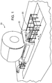
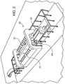
- a coiled metal web 10 is placed in a sample extraction system 20, where it rests on at least a pair of driven rollers 22, in an exemplary embodiment there are two driven rollers as illustrated in FIGs. 1 and 2 , that are capable of causing rotation of the coil about its central rotational axis.
- coiled sheet web is shown in the figures herein, other types of elongated coiled formed metal may be accommodated in the sampling system of the present invention, including by way of nonlimiting example rebar, round or rectangular barstock, pipe and tubing.
- a sample cutter 30 can be positioned parallel to and between the rollers 22, as well as the coil 10 central rotational axis. The sample cutter 30 is driven by a linear drive 24 along the X axis transverse the coiled sheet web.
- the sample cutter 30 includes a carriage 32 capable of being radially extended along axis D.
- the sample cutter 30 has a cutter head 34 that is driven by a motor 36.
- the sample cutter head 34 is pivoted about the X axis through an angular range of motion ⁇ .
- a disc-type slot milling tool may be used for the cutter head 34.
- the cutter head 34 or other cutting tool can have many desired cutting tip profile, including without limitation rectangular, triangular or other pointed tip, radiused-edge rounded lateral ends, arcuate, semi-circular, or oval profiles.
- Alternative cutting devices may be utilized, such as by way of non-limiting example plasma or electric discharge machining (EDM) heating cutters, broaching cutters or shears.
- EDM electric discharge machining
- At least one pair of rollers 38 can contact the outer circumferential surface of the coil 10.
- a proximity sensor 40 can confirm that the sample cutter carriage can be in contact position with the coil 10, and a thickness gauge sensor 42 is adapted to determine the thickness of the coil sheet material at multiple positions across the coil width.
- Information from a pair of sensors 40, 42 may be communicated to an automated control system for automatic operation of the system, as will be explained in greater detail herein.
- the automated control system can determine the average material thickness based on the thickness gauge sensor 42 sample readings.
- the cutter head 34 cuts transversely across the coil sheet web parallel to the coil rotational axis, but one may chose to skew the cut along any desired transverse angle or employ a non-linear cutting path. By cutting between the rollers 22, the coil weight maintains relative pressure between the cutter head 34 and the sheet web, thereby maintaining the web in taut coiled condition.
- the cutter head 34 can be positioned in such a way to create a cut channel of angle ⁇ and radial depth D into the sheet thickness, leaving a thin neck of material at the base of the cut channel.
- Cut angle ⁇ and depth D are chosen so that the sheet material 11 downstream of the coil may be separated from the main coil 10 without unduly distorting the cut edge remaining on the coil, or leaving a jagged edge.
- Web material composition, hardness, and thickness may be used as factors for determining cut angle ⁇ and depth D.
- the partial cut through the sheet thickness can reduce the force necessary to separate the remnant 11 downstream the cut from the rest of the roll after it laterally clears the driven rollers 22, but while the piece remains intact with both sides maintaining the same thickness it is easier to pass them over the rollers.
- the cut angle ⁇ can be set at zero degrees, orienting the cutting head 34 normal to the coil 10 web.
- the cut depth D can be chosen to cut all the way through the coil 10 web, so that there is no partial cut. Where no partial cut is desired a cutting head 34', having a triangular or other cross-sectional profile that tapers or otherwise necks to a narrower tip may be utilized, as shown in FIG. 7 .
- cut depth D may be approximated to be slightly less than the web thickness, in order to avoid damaging the web layer underlying the cut zone. In this way tolerance variations in either material web thickness (thinner range of acceptable variation) and/or the cut depth (deeper depth range) will not unduly risk cutting through the entire web and damaging the underlying web layer. Conversely, if the web is at the thicker range of acceptable variation and/or cut depth is in the shallower range, the web neck thickness at the bottom of the cut trough will still be sufficiently thin to facilitate "clean" separation of the sample 11 from the coil 10. Cut angle ⁇ may be generally limited to approximately 30 degrees, with 15 degree cut angle being sufficient for steel sheet of Rockwell C hardness between 17 and 32.
- Cutting depth D is chosen so that the remaining web neck at the bottom of the cutting trough is less than 0.5 mm (.020 inches), with 0.35 mm (0.015 inch) being satisfactory for the same hardness range steel. Angle and cutting depth of the trough may be varied for different materials and hardness at the discretion of one skilled in the art.
- the angular position ⁇ of the web end can be determined.
- the coil 10 is rotated by the rollers 22 so that the web end is a desired number of angular degrees away from the cutting head 34 that corresponds to the desired circumferential length of the sample to be cut from the coil.
- the coil end can be rotated so that ⁇ equals approximately 34 degrees relative to the cutting head 34'.
- An approximate 107 cm ( ⁇ 42 inch) diameter coil can be rotated so that ⁇ equals approximately 67 degrees relative to the cutting head 34', to create the same length sample.
- an approximate 61 cm ( ⁇ 24 inch) long scrap remnant 11 is first cut from the coil 10, and then an approximately 51 cm ( ⁇ 20 inch) long circumferential sample can be cut from the coil.
- the approximately 206 cm (81 inch) diameter coil can be initially rotated to align that end is approximately 34 degrees ( ⁇ ) downstream from (i.e., to the left of) the cutter head 34, as shown in FIG. 6A .
- the cut trough is formed in the web by the cutter head 34, whereupon the coil 10 is rotated clockwise or downstream from the cutter head, so that the cut is laterally clear of its proximal roller 22.
- a peeler 50 (for example the robot 50 shown in FIGs. 9 and 10 ) can shear the scrap generally tangentially relative to the coil 10 surface and breaks the scrap off from the coil along the cut trough narrowed neck.
- the coil 10 is rotated sufficiently clockwise or counterclockwise, as necessary, to set the desired length of the sample piece remnant 12 (in the present example, approximately 51 cm or ⁇ 20 inches) at approximately 32 degrees of angular rotation ⁇ relative to the cutter head 34.
- the next cut trough is created and the coil again rotated clockwise so that the sample piece 12 projects tangentially downstream from the coil outside the proximal roller 22, whereupon peeler 50 separates the sample from the coil.
- the cut channel created when making the angular cut facilitates smooth passage of the still unitized sheet material (with effectively no discontinuity in thickness) over the driven rollers 22 in either rotational direction.
- the unbanded coil 10 can be collected by a coil car and transfer device and banded at a separate station. While in this exemplary operational description a scrap remnant 11 was first cut from the coil 10 prior to cutting a sample remnant 12, one may choose to dispense with the need to remove scrap from the coil 10 end, or alternatively, unspool additional web material from the coil 10 before taking one or more samples. For example, if the coil sample is not on gauge or within tolerance for the gauge required at the proposed cutting position, then a cut can be made and the coil rotated to a new position where the coil is on gauge. The sample can then be taken at this new position.
- FIG. 8 An alternate embodiment sampling system 20' is shown in FIG. 8 .
- the coil 10 can be repositioned vertically in the Y axis dimension by roll alignment lift mechanism 60.
- the lift mechanism 60 includes a roll support saddle 62 that supports the driven rollers 22.
- a hydraulic lift 64 can raise and lower the support saddle 62 so that a coil 10 or smaller diameter coil 10' can be positioned relative to cutter 30'.
- cutting head 34 is aligned with the radial circumference of coil 10 or 10' at a 9 o'clock relative position rather than at a 6 o'clock position of the previous embodiment of FIGs. 1-7 .
- the cutter 30' can translate across the X or axial dimension of the coil 10, 10' on linear drive 24'.
- the cutter 30' is constructed and operates the same as the previously described cutter 30 of the sampling system 20, but as previously noted, aligns the cutting head 34 at the 9 o'clock position rather than at the 6 o'clock position between the rollers 22.
- the cutter 30' may be aligned radially along the coil 10, 10' circumference at any desired position by repositioning the roll alignment lift mechanism 60 up or down in the Y direction and pivoting the cutting head 34 relative to the coil along angle ⁇ .
- a coil tensioner mechanism 70 is adapted to maintain tension on wrapped layers against each other by exerting radially inwardly directed compressive (i.e., squeezing or clamping) tension on the coil 10 or 10'.
- the coil tensioner 70 inhibits coil relaxation that will otherwise disrupt desired taut tensioning of the coiled web when the web us unwound for cutting. By compressing or squeezing/clamping wrapped coil web layers against each other, web material upstream of the coil tensioner mechanism 70 remains tightly coiled and taut. While a coil tensioner mechanism 70 not shown in the sampling system 20 embodiment, such a mechanism may be used in that embodiment system in order to provide additional coiling tension.
- the coil tensioner mechanism 70 has a support stanchion 72 coupled to the support saddle 62, so that it moves with a coil 10 supported within the lift mechanism 60.
- the stanchion 72 does not need to be attached to the lift mechanism 60, and may for example be affixed to the factory floor with its own mechanism to move in coordination with the coil 10 in the Y or vertical dimension.
- the coil tensioner mechanism 70 includes a boom 76 pivotally coupled to the stanchion 72 by pin 74, so that the boom pivots along an angular path ⁇ .
- Tensioner roller 78 is rotatively coupled to the distal end of the boom 76, and exerts radially inwardly biased compressive force on the coil 10 by actuation of hydraulic cylinder 80, so that the coil 10 is compressed between the rollers 22 and the tensioner roller.
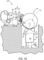
- FIGs. 9-11 show another embodiment sampling system 20".
- the cutter 30" is driven on wheels 24" in the Z access direction that is perpendicular to the coil 10 outer circumference.
- the cutter 30" has a cutter clamp 92, which is an elongated bar spanning across the axial length of the coil 10, having a cutter slot 94 for passage of cutter head 34 therethrough.
- the cutting head can be driven along a track in the cutter 30" across cutter slot 94 in the X axis to form a traversing cut across the coil 10 outer circumference.
- Cutter clamp 92 reciprocates in the Z axis direction (toward or away from the coil 10), driven by hydraulic cylinders 82 and piston rods 84 that are coupled thereto.
- Cutter 30" also has an elongated bar or bumper-like peeler clamp 96 affixed thereto that traverses the coil 10 outer circumference, for abutment against the coil 10 outer circumference as the cutter is translated in the Z access direction.
- the peeler clamp 96 has a tapered bottom edge to facilitate extension of a scrap end remnant 11 (or sample end remnant 12) thereover and a clearance slot 98 traversing the clamp.
- the cutter 30" In operation of the sampling system 20" the cutter 30" is abutted to contact against the coil 10, and the cutter clamp 92 is withdrawn in the Z direction away from the coil 10, creating an opening gap between itself and the peeler clamp 96.
- the coil 10 end remnant e.g., scrap 11 or sample 12 end
- the coil 10 end remnant is threaded through that gap by rotating the coil clockwise with the rollers 22, so that the coil end remnant rides over the peeler clamp 96 tapered bottom edge.
- cutter clamp 92 When a desired length of the coil 10 end extends downstream of the cutter head, e.g., by rotating the coil 10 a desired number of degrees ⁇ with the rollers 22, cutter clamp 92 is reciprocated toward peeler clamp 96, effectively squeezing or tensioning the coil end therebetween as a coil tensioner mechanism.
- Cutter head 34 is advanced into the coil 10 material in the D direction and traversed across a desired axial width of the material in the X axis direction (e.g., across the entire material width in order to facilitate removal of a scrap end 11 sample 12.
- Cutter head 34 may be advanced or retracted in the D direction by a separate drive axis, or may be manually set by pre-extending it into the cutter clamp 92 cutter slot 94, so that a desired depth cut is formed in the coil 10 material. Cut depth into the coil 10 web material may be selectively set as a partial cut or a full through cut. Notch 98 formed in the peeler clamp 96 allows cutter head 34 clearance if the cutter head is extended beyond the web material through cut depth.
- Robot 50 is a peeler mechanism to grab the free end of the cut scrap end 11 or sample end 12. If a through cut is performed the robot 50 holds the end 11 or 12 and can transport the end to a desired location. If a partial cut is performed in the end 11 or 12, the robot 50 can be used to snap the remnant end off the web material remaining on coil 10. After cut completion and removal of the end 11 or 12, remaining web material on the coil 10 can be prepared for rebanding by counter rotating the coil in the counterclockwise direction so that the remaining coil free end is proximal or under one of the rollers 22. While not shown, the tensioner mechanism 70 may be used with the sampling system 20" embodiment.
- automated control system 100 includes a communication bus 110 communicatively coupled to a controller having a processor including accessible memory, such as programmable logic controller (PLC) 120 with memory 122.
- PLC programmable logic controller
- An exemplary bus 110 communication protocol is industrial Ethernet.
- the memory 122 includes software and/or firmware instruction sets stored therein that when executed by the PLC processor controls operation of system drives 130 and communications cards 140 that are in communication with the system 20, 20', 20" including: its driven rollers, the cutter 30, 30', 30", sensors such as the coil proximity sensor 40 and thickness gauge sensor 42, the sample peeler (e.g., robot) 50, the roll alignment lift 60 and the coil tensioner mechanism 70.
- the PLC 120 may be in communication via bus 110 with an engineering station 150 for monitoring and altering system operational parameters.
- a human machine interface (HMI) 160 may also be in communication with the system 100 to enable manual control and monitoring by factory personnel on the shop floor or remote operational station.
Landscapes
- Engineering & Computer Science (AREA)
- Mechanical Engineering (AREA)
- Physics & Mathematics (AREA)
- Health & Medical Sciences (AREA)
- Life Sciences & Earth Sciences (AREA)
- Chemical & Material Sciences (AREA)
- Analytical Chemistry (AREA)
- Biochemistry (AREA)
- General Health & Medical Sciences (AREA)
- General Physics & Mathematics (AREA)
- Immunology (AREA)
- Pathology (AREA)
- Sampling And Sample Adjustment (AREA)
- Winding, Rewinding, Material Storage Devices (AREA)
Description
- Embodiments of the present invention relate to trimming ends from a coil of coiled formed metal without distorting the material remaining on the coil and maintaining the coil layers tightly wrapped in taut tension for banding or rebanding. Coil ends are trimmed for obtaining test and inspection samples, as well as for trimming scrap tail ends.
- A known system places a banded metal coil of tightly wrapped formed elongated sheet material (e.g., a sheet web) between spaced parallel rollers, removes bands that maintain coiled metal layers in a tightly wrapped, taut layer condition, and thereafter unwinds a portion of the coil end so that a desired length extends generally tangentially from the coil laterally clear from the rollers. The tangential end is selectively cut through the full material thickness normal to its surface by a shear. The sheared-off tangential end separates from the roll and drops into a collection container. A remnant stub projects generally tangentially from the roller in a relaxed uncoiled deformed state that inhibits tight re-rolling and banding of the sampled coil. The sheared edge remaining on the coil may have localized distortion and a relatively blunt edge generally along the coil's radial circumference that may hinder further rotational maneuvering of the coil on the rollers. The known sampling system is monitored and controlled by a human operator.
- A sampling system according to the preamble of claim 1 and a method according to the preamble of
claim 10 are e.g. known fromDE-A1-4411905 . - Accordingly, embodiments of the present invention include the creation a coil trimming and sampling system that, in one aspect reduces and in yet another prevents deformation of the coil material dimensions during the trimming or sampling procedure, and facilitates rebanding of the coil in its taut, fully coiled state.
- Another embodiment of the present invention includes a coil trimming and sampling system that facilitates a clean separation of the coil sample from the coil while minimizing localized coil material dimensional deformation along the separation edge.
- An additional embodiment of the present invention includes a coil trimming and sampling system that facilitates passage of the separation edge remaining on the coil over the rollers as the coil is manipulated, including for re-strapping the coil in it tensioned wrapped state.
- Another exemplary embodiment includes an automated trimming and sample extraction system and method that does not require human intervention between sampling steps.
- These and other embodiments can be achieved by a system and method for trimming or extracting a sample from the end of a metal coil. Ends are trimmed and/or samples are extracted from an end strip of a tensioned metal coil that is resting on rollers. In one embodiment, a cut channel is formed between the rollers by cutting at an angle relative to the coil outer surface. Coil weight inhibits coil relaxation along the cut channel. The coil can be rotated so that the cut channel clears the rollers laterally and the scrap end or sample downstream the cut channel is separated off the coil.
- In embodiments of the present invention, cut channel depth and angle may be selected so that the trimmed/sampled end's full material thickness is not penetrated. The uncut necked material thickness remaining at the depth of the cut channel formation is selected to allow a clean separation of the material. Angular cutting reduces deformation of the material along the edge remaining on the coil and reduces the force required to separate the strip downstream the cut channel. If the separation force is less than the material's tensile strength there is less likelihood that the edge will be deformed. After sample extraction the coil maintains rolled tautness for ease of rebanding.
- Embodiments of the present invention include a sampling system according to claim 1.
- Embodiments of the present invention additionally include a method according to
claim 10. - Further features of embodiments of the present invention, and the advantages offered thereby, are explained in greater detail hereinafter with reference to specific embodiments illustrated in the accompanying drawings, wherein like elements are indicated by like reference designators.
- The teachings of the present invention can be readily understood by considering the following detailed description in conjunction with the accompanying drawings, in which:
-
FIG. 1 is a perspective view of a system loaded with a metal coil, in accordance with an exemplary embodiment of the present invention; -
FIG. 2 is a perspective view of the system ofFIG. 1 without a metal coil, in accordance with an exemplary embodiment of the present invention; -
FIG. 3 is a front elevational view of a coil sample cutter, in accordance with an exemplary embodiment of the present invention; -
FIG. 4 is a detailed view ofFIG. 3 , in accordance with an exemplary embodiment of the present invention; -
FIG. 5 is a longitudinal sectional view of a coil sheet showing cutting angle and profile made by the coil sample cutter, in accordance with an exemplary embodiment of the present invention; -
FIGs. 6A-6D is a series of schematic end views showing coil rotational positions during steps of a sampling method, in accordance with an exemplary embodiment of the present invention; -
FIG. 7 shows exemplary coil rotational positions for two coil diameters, in accordance with an exemplary embodiment of the present invention; -
FIG. 8 is a schematic side elevational view of a system loaded with a metal coil, in accordance with another exemplary embodiment of the present invention; -
FIG. 9 is a schematic side elevational view of a system loaded with a metal coil, in accordance with an additional exemplary embodiment of the present invention, prior to coil clamping; -
FIG. 10 is a schematic side elevational view of a system loaded with a metal coil, similar to that ofFIG. 9 , wherein the coil is clamped within the sampling system.; -
FIG. 11 is a partial cross-sectional plan view of the system ofFIG. 10 , taken along 11-11 thereof; and -
FIG. 12 is a schematic diagram of an automation system for operating the system, in accordance with an exemplary embodiment of the present invention. - To facilitate understanding, identical reference numerals have been used, where possible, to designate identical elements that are common to the figures.
- After considering the following description, those skilled in the art will clearly realize that the teachings of my invention can be readily utilized in coiled metal sample extraction systems and methods.
- Referring generally to
FIGs. 1 and2 , showing one exemplary embodiment of the present invention, acoiled metal web 10 is placed in asample extraction system 20, where it rests on at least a pair of drivenrollers 22, in an exemplary embodiment there are two driven rollers as illustrated inFIGs. 1 and2 , that are capable of causing rotation of the coil about its central rotational axis. While coiled sheet web is shown in the figures herein, other types of elongated coiled formed metal may be accommodated in the sampling system of the present invention, including by way of nonlimiting example rebar, round or rectangular barstock, pipe and tubing. Asample cutter 30 can be positioned parallel to and between therollers 22, as well as thecoil 10 central rotational axis. Thesample cutter 30 is driven by alinear drive 24 along the X axis transverse the coiled sheet web. - Referring to
FIGs. 3 and4 , thesample cutter 30 includes acarriage 32 capable of being radially extended along axis D. Thesample cutter 30 has acutter head 34 that is driven by amotor 36. Thesample cutter head 34 is pivoted about the X axis through an angular range of motion θ. A disc-type slot milling tool may be used for thecutter head 34. Thecutter head 34 or other cutting tool can have many desired cutting tip profile, including without limitation rectangular, triangular or other pointed tip, radiused-edge rounded lateral ends, arcuate, semi-circular, or oval profiles. Alternative cutting devices may be utilized, such as by way of non-limiting example plasma or electric discharge machining (EDM) heating cutters, broaching cutters or shears. At least one pair ofrollers 38 can contact the outer circumferential surface of thecoil 10. Aproximity sensor 40 can confirm that the sample cutter carriage can be in contact position with thecoil 10, and athickness gauge sensor 42 is adapted to determine the thickness of the coil sheet material at multiple positions across the coil width. Information from a pair ofsensors thickness gauge sensor 42 sample readings. As illustrated, thecutter head 34 cuts transversely across the coil sheet web parallel to the coil rotational axis, but one may chose to skew the cut along any desired transverse angle or employ a non-linear cutting path. By cutting between therollers 22, the coil weight maintains relative pressure between thecutter head 34 and the sheet web, thereby maintaining the web in taut coiled condition. - As shown in
FIG. 5 , thecutter head 34 can be positioned in such a way to create a cut channel of angle θ and radial depth D into the sheet thickness, leaving a thin neck of material at the base of the cut channel. Cut angle θ and depth D are chosen so that thesheet material 11 downstream of the coil may be separated from themain coil 10 without unduly distorting the cut edge remaining on the coil, or leaving a jagged edge. Web material composition, hardness, and thickness may be used as factors for determining cut angle θ and depth D. The partial cut through the sheet thickness can reduce the force necessary to separate the remnant 11 downstream the cut from the rest of the roll after it laterally clears the drivenrollers 22, but while the piece remains intact with both sides maintaining the same thickness it is easier to pass them over the rollers. The cut angle θ can be set at zero degrees, orienting the cuttinghead 34 normal to thecoil 10 web. The cut depth D can be chosen to cut all the way through thecoil 10 web, so that there is no partial cut. Where no partial cut is desired a cutting head 34', having a triangular or other cross-sectional profile that tapers or otherwise necks to a narrower tip may be utilized, as shown inFIG. 7 . - By cutting the coil sheet material at an angle θ greater than zero degrees, cut depth D may be approximated to be slightly less than the web thickness, in order to avoid damaging the web layer underlying the cut zone. In this way tolerance variations in either material web thickness (thinner range of acceptable variation) and/or the cut depth (deeper depth range) will not unduly risk cutting through the entire web and damaging the underlying web layer. Conversely, if the web is at the thicker range of acceptable variation and/or cut depth is in the shallower range, the web neck thickness at the bottom of the cut trough will still be sufficiently thin to facilitate "clean" separation of the
sample 11 from thecoil 10. Cut angle θ may be generally limited to approximately 30 degrees, with 15 degree cut angle being sufficient for steel sheet of Rockwell C hardness between 17 and 32. Cutting depth D is chosen so that the remaining web neck at the bottom of the cutting trough is less than 0.5 mm (.020 inches), with 0.35 mm (0.015 inch) being satisfactory for the same hardness range steel. Angle and cutting depth of the trough may be varied for different materials and hardness at the discretion of one skilled in the art. - Referring to
FIGs. 6-9 , when thecoil 10 is positioned between the drivenrollers 22, the angular position α of the web end can be determined. Thecoil 10 is rotated by therollers 22 so that the web end is a desired number of angular degrees away from the cuttinghead 34 that corresponds to the desired circumferential length of the sample to be cut from the coil. Using the example ofFIG. 7 , if one wishes to cut an approximate 61 cm (∼24 inch) sample from an approximate 206 cm (∼81 inch)diameter coil 10, the coil end can be rotated so that α equals approximately 34 degrees relative to the cutting head 34'. An approximate 107 cm (∼42 inch) diameter coil, however, can be rotated so that α equals approximately 67 degrees relative to the cutting head 34', to create the same length sample. - In the exemplary system operational sequence of
FIGs. 6A-6D , an approximate 61 cm (∼24 inch)long scrap remnant 11 is first cut from thecoil 10, and then an approximately 51 cm (∼20 inch) long circumferential sample can be cut from the coil. In order to cut the scrap, the approximately 206 cm (81 inch) diameter coil can be initially rotated to align that end is approximately 34 degrees (α) downstream from (i.e., to the left of) thecutter head 34, as shown inFIG. 6A . The cut trough is formed in the web by thecutter head 34, whereupon thecoil 10 is rotated clockwise or downstream from the cutter head, so that the cut is laterally clear of itsproximal roller 22. In this position thescrap remnant 11 is no longer taut on thecoil 10 and relaxes to project generally tangentially from the coil surface. Apeeler 50, (for example therobot 50 shown inFIGs. 9 and10 ) can shear the scrap generally tangentially relative to thecoil 10 surface and breaks the scrap off from the coil along the cut trough narrowed neck. - After the scrap piece is removed, the
coil 10 is rotated sufficiently clockwise or counterclockwise, as necessary, to set the desired length of the sample piece remnant 12 (in the present example, approximately 51 cm or ∼20 inches) at approximately 32 degrees of angular rotation α relative to thecutter head 34. The next cut trough is created and the coil again rotated clockwise so that thesample piece 12 projects tangentially downstream from the coil outside theproximal roller 22, whereuponpeeler 50 separates the sample from the coil. The cut channel created when making the angular cut facilitates smooth passage of the still unitized sheet material (with effectively no discontinuity in thickness) over the drivenrollers 22 in either rotational direction. After thesample 12 is removed from thecoil 10, it can be rebanded manually while on the sampling system. Alternatively, theunbanded coil 10 can be collected by a coil car and transfer device and banded at a separate station. While in this exemplary operational description ascrap remnant 11 was first cut from thecoil 10 prior to cutting asample remnant 12, one may choose to dispense with the need to remove scrap from thecoil 10 end, or alternatively, unspool additional web material from thecoil 10 before taking one or more samples. For example, if the coil sample is not on gauge or within tolerance for the gauge required at the proposed cutting position, then a cut can be made and the coil rotated to a new position where the coil is on gauge. The sample can then be taken at this new position. - An alternate embodiment sampling system 20' is shown in
FIG. 8 . In this embodiment thecoil 10 can be repositioned vertically in the Y axis dimension by rollalignment lift mechanism 60. Thelift mechanism 60 includes aroll support saddle 62 that supports the drivenrollers 22. Ahydraulic lift 64 can raise and lower thesupport saddle 62 so that acoil 10 or smaller diameter coil 10' can be positioned relative to cutter 30'. In this embodiment, cuttinghead 34 is aligned with the radial circumference ofcoil 10 or 10' at a 9 o'clock relative position rather than at a 6 o'clock position of the previous embodiment ofFIGs. 1-7 . - The cutter 30' can translate across the X or axial dimension of the
coil 10, 10' onlinear drive 24'. The cutter 30' is constructed and operates the same as the previously describedcutter 30 of thesampling system 20, but as previously noted, aligns the cuttinghead 34 at the 9 o'clock position rather than at the 6 o'clock position between therollers 22. The cutter 30' may be aligned radially along thecoil 10, 10' circumference at any desired position by repositioning the rollalignment lift mechanism 60 up or down in the Y direction and pivoting the cuttinghead 34 relative to the coil along angle θ. - A
coil tensioner mechanism 70 is adapted to maintain tension on wrapped layers against each other by exerting radially inwardly directed compressive (i.e., squeezing or clamping) tension on thecoil 10 or 10'. Thecoil tensioner 70 inhibits coil relaxation that will otherwise disrupt desired taut tensioning of the coiled web when the web us unwound for cutting. By compressing or squeezing/clamping wrapped coil web layers against each other, web material upstream of thecoil tensioner mechanism 70 remains tightly coiled and taut. While acoil tensioner mechanism 70 not shown in thesampling system 20 embodiment, such a mechanism may be used in that embodiment system in order to provide additional coiling tension. Thecoil tensioner mechanism 70 has asupport stanchion 72 coupled to thesupport saddle 62, so that it moves with acoil 10 supported within thelift mechanism 60. Alternatively, thestanchion 72 does not need to be attached to thelift mechanism 60, and may for example be affixed to the factory floor with its own mechanism to move in coordination with thecoil 10 in the Y or vertical dimension. Thecoil tensioner mechanism 70 includes aboom 76 pivotally coupled to thestanchion 72 bypin 74, so that the boom pivots along an angular path β.Tensioner roller 78 is rotatively coupled to the distal end of theboom 76, and exerts radially inwardly biased compressive force on thecoil 10 by actuation ofhydraulic cylinder 80, so that thecoil 10 is compressed between therollers 22 and the tensioner roller. -
FIGs. 9-11 show anotherembodiment sampling system 20". In this embodiment thecutter 30" is driven onwheels 24" in the Z access direction that is perpendicular to thecoil 10 outer circumference. Thecutter 30" has acutter clamp 92, which is an elongated bar spanning across the axial length of thecoil 10, having acutter slot 94 for passage ofcutter head 34 therethrough. The cutting head can be driven along a track in thecutter 30" acrosscutter slot 94 in the X axis to form a traversing cut across thecoil 10 outer circumference.Cutter clamp 92 reciprocates in the Z axis direction (toward or away from the coil 10), driven byhydraulic cylinders 82 andpiston rods 84 that are coupled thereto.Cutter 30" also has an elongated bar or bumper-like peeler clamp 96 affixed thereto that traverses thecoil 10 outer circumference, for abutment against thecoil 10 outer circumference as the cutter is translated in the Z access direction. Thepeeler clamp 96 has a tapered bottom edge to facilitate extension of a scrap end remnant 11 (or sample end remnant 12) thereover and aclearance slot 98 traversing the clamp. - In operation of the
sampling system 20" thecutter 30" is abutted to contact against thecoil 10, and thecutter clamp 92 is withdrawn in the Z direction away from thecoil 10, creating an opening gap between itself and thepeeler clamp 96. Next, thecoil 10 end remnant (e.g., scrap 11 orsample 12 end) is threaded through that gap by rotating the coil clockwise with therollers 22, so that the coil end remnant rides over thepeeler clamp 96 tapered bottom edge. When a desired length of thecoil 10 end extends downstream of the cutter head, e.g., by rotating the coil 10 a desired number of degrees α with therollers 22,cutter clamp 92 is reciprocated towardpeeler clamp 96, effectively squeezing or tensioning the coil end therebetween as a coil tensioner mechanism.Cutter head 34 is advanced into thecoil 10 material in the D direction and traversed across a desired axial width of the material in the X axis direction (e.g., across the entire material width in order to facilitate removal of ascrap end 11sample 12.Cutter head 34 may be advanced or retracted in the D direction by a separate drive axis, or may be manually set by pre-extending it into thecutter clamp 92cutter slot 94, so that a desired depth cut is formed in thecoil 10 material. Cut depth into thecoil 10 web material may be selectively set as a partial cut or a full through cut.Notch 98 formed in thepeeler clamp 96 allowscutter head 34 clearance if the cutter head is extended beyond the web material through cut depth.Robot 50 is a peeler mechanism to grab the free end of thecut scrap end 11 orsample end 12. If a through cut is performed therobot 50 holds theend end robot 50 can be used to snap the remnant end off the web material remaining oncoil 10. After cut completion and removal of theend coil 10 can be prepared for rebanding by counter rotating the coil in the counterclockwise direction so that the remaining coil free end is proximal or under one of therollers 22. While not shown, thetensioner mechanism 70 may be used with thesampling system 20" embodiment. - The sampling system embodiments 20, 20', 20" may be incorporated into a fully automated sampling system. Referring to
FIG. 12 automated control system 100 includes acommunication bus 110 communicatively coupled to a controller having a processor including accessible memory, such as programmable logic controller (PLC) 120 withmemory 122. Anexemplary bus 110 communication protocol is industrial Ethernet. Thememory 122 includes software and/or firmware instruction sets stored therein that when executed by the PLC processor controls operation of system drives 130 andcommunications cards 140 that are in communication with thesystem cutter coil proximity sensor 40 andthickness gauge sensor 42, the sample peeler (e.g., robot) 50, theroll alignment lift 60 and thecoil tensioner mechanism 70. Communication and control among thePLC 120, the system drives 130,communication cards 140 and devices coupled thereto is established via a suitable industrial control bus protocol, such as Profibus DP protocol available through the owner of this filed application. ThePLC 120 may be in communication viabus 110 with anengineering station 150 for monitoring and altering system operational parameters. A human machine interface (HMI) 160 may also be in communication with thesystem 100 to enable manual control and monitoring by factory personnel on the shop floor or remote operational station.
Claims (18)
- A sampling system for extracting a sample from an end strip of a coil having wrapped layers of coiled formed elongated metal, comprising:a pair of generally parallel spaced drive rollers (22) that are driven by a roller drive system coupled thereto, for selective rotation of a coil about a coil central axis that is oriented parallel to the rollers;a cutter (30), proximal the rollers, for alignment with a circumference of a metal coil resting on the driven rollers, the cutter having a cutter drive mechanism (24) for selectively advancing the cutter into the coil and selectively traversing the cutter along the coil circumference; anda coil tensioner mechanism (70) for maintaining tension on wrapped layers against each other in a metal coil resting on the rollers, in order to inhibit relaxation of the layerscharacterized in that the cutter drive mechanism (24) is configured to orient the cutter so that it is capable of selectively forming a cut channel within a layer of the coiled metal at a range of angles from zero to ninety degrees relative to a coil radius, and a selective range of cut depths up to and including through entire thickness of a layer of the coiled metal.
- The system of claim 1, the cutter further comprising a metal cutting device (34) selected from the group consisting of milling tool cutters, shears, plasma heating cutters, electric discharge machining (EDM) cutters and broaching cutters.
- The system of claim 2, wherein the cutter (30) is a disc-type slot milling tool cutter having a cutting profile selected from the group consisting of rectangular, radiused edge, ball, triangular and necked distal tip profiles.
- The system of claim 1, wherein the cutter drive mechanism (24) is configured to orient the cutter (30) so that it is capable of selectively forming a cut channel within the coil metal traversing axially across at least a portion of the coil.
- The system of claim 1, wherein the cutter (30) is oriented under and between the driven rollers, and the driven rollers are the coil tensioner mechanism.
- The system of claim 1, wherein the coil tensioner mechanism (70) comprises a biased tensioner roller (78) oriented above the driven rollers (22), for compressing wrapped layers of a metal coil resting on the rollers.
- The system of claim 1 further comprising a lift mechanism (60) coupled to the driven rollers, for selectively varying roller height relative to the cutter.
- The system of claim 1 further comprising an automated control system (100) coupled to the driven rollers (22) and cutter drive systems for selectively extracting a sample from an end strip of a coil placed on the rollers without human operator intervention.
- The system of claim 1, wherein the coil tensioner mechanism (70) comprises a pair of opposed clamps that are configured to be selectively oriented relative to each other in an open position defining a gap therebetween for receipt of material forming an end of a coil therebetween, and a closed position that clamps the coil end material therebetween.
- A method for extracting a sample from an end strip of a coil having wrapped layers of coiled formed elongated metal, comprising:placing a banded coil, having a central axis, on a pair of generally parallel spaced driven rollers (22) so that the coil central axis is oriented parallel to the driven rollers;maintaining tension on wrapped layers in the coil against each other with a coil tensioner mechanism (70) and unbanding the coil;rotating the coil with the driven rollers (22) so that a desired length of a coil end strip is oriented downstream a cutter (30) that is proximal the driven rollers;cutting the end strip by selectively advancing and traversing the cutter into the coil in any desired sequence; andextracting the end strip from the coilcharacterized in that
the cutting step further comprises selectively forming a cut channel within a layer of the coiled metal at a range of angles from zero to ninety degrees relative to a coil radius, and a selective range of cut depths up to and including through entire thickness of a layer of the coiled metal by orienting the cutter (30) with a cutter drive mechanism (24). - The method of claim 10, further comprising rebanding the coil after the extracting step.
- The method of claim 10, wherein the cutter (30) is oriented under and between the driven rollers (22), and the driven rollers are the coil tensioner mechanism by weight of the coil compressing the coil layers against the driven rollers.
- The method of claim 10 wherein the coil tensioner mechanism (70) comprises a biased tensioner roller (78) oriented to compress a coil placed in the sampling system between itself and the driven rollers.
- The method of claim 10, wherein the cut channel angle is between 15 - 30 degrees and cutting depth is sufficiently shallow to leave a remaining thickness of uncut metal in the layer less than 0.5 millimeters (0.020 inch).
- The method of claim 10, wherein the cutting step further comprises selectively traversing the cutter axially across the entire layer in order to extract the end strip from the coil during the extracting step.
- The method of claim 11, wherein the cutter further comprises a metal cutting device selected from the group consisting of milling tool cutters; shears; plasma heating cutters; electric discharge machining (EDM) cutters; broaching cutters; and disc-type slot milling tool cutter having a cutting profile selected from the group consisting of rectangular, radiused edge, ball, triangular and necked distal tip profiles.
- The method of claim 10, wherein the system further comprises an automated control system (100) coupled to the driven rollers and cutter drive systems for performing the rotating and cutting steps without human operator intervention.
- The method of claim 10, wherein the coil tensioner mechanism (70) comprises a pair of opposed clamps that are selectively oriented relative to each other in an open position defining a gap therebetween for receipt of material forming an end of a coil therebetween, and a closed position that clamps the coil end material therebetween.
Applications Claiming Priority (4)
| Application Number | Priority Date | Filing Date | Title |
|---|---|---|---|
| US201161434630P | 2011-01-20 | 2011-01-20 | |
| US201161488874P | 2011-05-23 | 2011-05-23 | |
| US13/333,845 US9149848B2 (en) | 2011-01-20 | 2011-12-21 | Method and apparatus for trimming a sample from a coiled metal web |
| PCT/US2012/021845 WO2012100036A1 (en) | 2011-01-20 | 2012-01-19 | Method and apparatus for trimming a sample from a coiled metal web |
Publications (2)
| Publication Number | Publication Date |
|---|---|
| EP2665568A1 EP2665568A1 (en) | 2013-11-27 |
| EP2665568B1 true EP2665568B1 (en) | 2017-12-27 |
Family
ID=45755500
Family Applications (1)
| Application Number | Title | Priority Date | Filing Date |
|---|---|---|---|
| EP12705518.4A Active EP2665568B1 (en) | 2011-01-20 | 2012-01-19 | Method and apparatus for trimming a sample from a coiled metal web |
Country Status (5)
| Country | Link |
|---|---|
| US (1) | US9149848B2 (en) |
| EP (1) | EP2665568B1 (en) |
| CN (1) | CN103328122B (en) |
| BR (1) | BR112013018636B1 (en) |
| WO (1) | WO2012100036A1 (en) |
Families Citing this family (14)
| Publication number | Priority date | Publication date | Assignee | Title |
|---|---|---|---|---|
| EP2444171A1 (en) * | 2010-10-22 | 2012-04-25 | Siemens VAI Metals Technologies GmbH | Transport system, transport vehicle and method for transporting metal coils |
| DE102011077461A1 (en) * | 2011-02-23 | 2012-08-23 | Sms Siemag Ag | Apparatus and method for taking a sample from a coil |
| WO2013151996A1 (en) * | 2012-04-02 | 2013-10-10 | Jac Operations, Inc. | Transverse trough coil car with modular trough forming assemblies and method of forming same |
| US9393638B2 (en) * | 2013-01-25 | 2016-07-19 | Plasma Automation Inc. | System and method for plasma cutting sheet metal in an automated coil-line machine |
| CN103662853B (en) * | 2013-11-27 | 2016-02-10 | 中色科技股份有限公司 | A kind of metal coiled material piler coiled material fender guard |
| EP3067127B1 (en) * | 2015-03-12 | 2019-10-09 | Primetals Technologies Austria GmbH | Device for inspecting and sampling a reeled metal strip |
| DE102015208220A1 (en) * | 2015-05-04 | 2016-11-10 | Sms Group Gmbh | Bund transport pallet, federal transport vehicle, method for discharging a coil wound on a winding system |
| CN105268765B (en) * | 2015-10-23 | 2017-10-10 | 首钢京唐钢铁联合有限责任公司 | Control method for coil stripping of hot-rolled thick strip steel |
| SE542363C2 (en) | 2017-02-22 | 2020-04-14 | Core Link Ab | Method and apparatus for removing wrapping from rolls |
| CN109013789B (en) * | 2018-06-26 | 2020-03-17 | 安徽玄同工业设计有限公司 | Coil stock winding mechanism |
| CN112082801B (en) * | 2020-08-13 | 2024-07-02 | 宁波北新建材有限公司 | An online sampling and detection device and detection method for a gypsum board production line |
| CN114309904B (en) * | 2020-09-27 | 2023-10-20 | 中冶宝钢技术服务有限公司 | Steel coil repairing and cutting device and cutting process thereof |
| CN112743170B (en) * | 2020-12-29 | 2024-02-06 | 苏州吉雄精密机械有限公司 | High-precision adjustable die tapping device |
| CN116007979A (en) * | 2022-12-28 | 2023-04-25 | 二重(德阳)重型装备有限公司 | Thick high-strength steel coil sampling device and sampling method |
Family Cites Families (12)
| Publication number | Priority date | Publication date | Assignee | Title |
|---|---|---|---|---|
| DE2815969C3 (en) | 1978-04-13 | 1985-08-22 | Siemag Transplan Gmbh, 5902 Netphen | Device for opening collars |
| DE2924379A1 (en) | 1979-06-16 | 1981-01-08 | Siemag Transplan Gmbh | SCISSOR SYSTEM FOR BOWLING THE ENDS AND / OR FOR SEPARATING SAMPLE PIECES ON TAPE WINDED ROLLING ROLL OR THE LIKE. |
| DE3004952C2 (en) * | 1980-02-09 | 1982-02-18 | Schloemann-Siemag AG, 4000 Düsseldorf | Device for separating crop ends or sample strips from metal tape wound into bundles |
| DE3028538A1 (en) | 1980-07-28 | 1982-02-25 | Siemag Transplan Gmbh, 5902 Netphen | SCISSOR SYSTEM FOR BOWLING THE ENDS AND / OR FOR SEPARATING SAMPLE PIECES ON TAPE WINDED ROLLING ROLL OR THE LIKE. |
| IT1233788B (en) * | 1989-05-12 | 1992-04-17 | Gd Spa | METHOD FOR THE REGISTRATION AND THE CONTROL OF A CUTTING DEVICE OF A TAPE IN A PRODUCT PACKAGING MACHINE |
| IT1248124B (en) | 1991-01-28 | 1995-01-05 | Danieli Off Mecc | HEAD CUTTING MACHINE AND SAMPLING FROM TAPE ROLLS (COILS) |
| FI93275C (en) | 1993-04-29 | 1995-03-10 | Rautaruukki Oy | Method and apparatus for sampling from tape reel |
| JP3532286B2 (en) | 1995-03-31 | 2004-05-31 | Jfeスチール株式会社 | Coil binding / unwinding device and coil tail edge protection hardware |
| JPH0985315A (en) * | 1995-09-27 | 1997-03-31 | Kawasaki Steel Corp | Method and apparatus for determining quality of steel strip coil |
| AT501782B1 (en) | 2005-04-21 | 2008-12-15 | Voest Alpine Ind Anlagen | APPARATUS AND METHOD FOR SAMPLING |
| DE102007017383B4 (en) | 2007-02-08 | 2015-03-26 | Sms Siemag Aktiengesellschaft | Device for binding a coil |
| DE102011077461A1 (en) | 2011-02-23 | 2012-08-23 | Sms Siemag Ag | Apparatus and method for taking a sample from a coil |
-
2011
- 2011-12-21 US US13/333,845 patent/US9149848B2/en active Active
-
2012
- 2012-01-19 CN CN201280006115.0A patent/CN103328122B/en active Active
- 2012-01-19 WO PCT/US2012/021845 patent/WO2012100036A1/en not_active Ceased
- 2012-01-19 EP EP12705518.4A patent/EP2665568B1/en active Active
- 2012-01-19 BR BR112013018636-4A patent/BR112013018636B1/en active IP Right Grant
Also Published As
| Publication number | Publication date |
|---|---|
| CN103328122B (en) | 2016-08-10 |
| US9149848B2 (en) | 2015-10-06 |
| BR112013018636A2 (en) | 2016-10-18 |
| CN103328122A (en) | 2013-09-25 |
| WO2012100036A1 (en) | 2012-07-26 |
| EP2665568A1 (en) | 2013-11-27 |
| BR112013018636B1 (en) | 2020-06-02 |
| US20120187091A1 (en) | 2012-07-26 |
Similar Documents
| Publication | Publication Date | Title |
|---|---|---|
| US9149848B2 (en) | Method and apparatus for trimming a sample from a coiled metal web | |
| US4155238A (en) | Metal web handling method, apparatus and coil construct | |
| EP1402986B1 (en) | Method and apparatus for cutting out of sheet blanks | |
| EP1916042B1 (en) | Line for straightening strip material wrapped to a coil and for feeding in the same to a processing machine | |
| US4173313A (en) | Metal web handling method, apparatus and coil construct | |
| US9157836B2 (en) | Method and device for removing a sample from a coil | |
| CN102066017B (en) | Device and method for winding sheared waste from steel band edges | |
| EP3549689B1 (en) | Strip profiling line comprising a cutting device | |
| KR101061374B1 (en) | Manufacturing method and apparatus for strip strip for cable ties | |
| EP2018809B1 (en) | Skinning method and device for cutting meat with skin | |
| DE2826026B2 (en) | Device for the automatic cutting, winding and removal of a tape used to hold a bundle together | |
| EP4427597A1 (en) | An apparatus for removing an outer covering from food products and the like | |
| JPH048127B2 (en) | ||
| US4171080A (en) | Steel metal web handling method | |
| EP3067127B1 (en) | Device for inspecting and sampling a reeled metal strip | |
| CA2986484A1 (en) | Travelling saw sample cut system | |
| JP2635673B2 (en) | Device to prevent loosening at the beginning of coil winding | |
| CN104128801A (en) | Aluminum strip shearing unit for transformer | |
| CN204053492U (en) | A kind of transformer aluminium strip shears unit | |
| WO2011049489A1 (en) | Arrangement for de-strapping of coils | |
| CA1088486A (en) | Sheet metal web handling method, apparatus and coil construct | |
| JP3142372U (en) | Stopper insertion device | |
| CN202556464U (en) | Shearing device for offcut | |
| DE2826026C (en) | Device for the automatic cutting, winding and removal of a tape used to hold a bundle together | |
| WO2016162147A1 (en) | Foil coiling system and method |
Legal Events
| Date | Code | Title | Description |
|---|---|---|---|
| PUAI | Public reference made under article 153(3) epc to a published international application that has entered the european phase |
Free format text: ORIGINAL CODE: 0009012 |
|
| 17P | Request for examination filed |
Effective date: 20130718 |
|
| AK | Designated contracting states |
Kind code of ref document: A1 Designated state(s): AL AT BE BG CH CY CZ DE DK EE ES FI FR GB GR HR HU IE IS IT LI LT LU LV MC MK MT NL NO PL PT RO RS SE SI SK SM TR |
|
| DAX | Request for extension of the european patent (deleted) | ||
| RAP1 | Party data changed (applicant data changed or rights of an application transferred) |
Owner name: PRIMETALS TECHNOLOGIES USA LLC |
|
| GRAP | Despatch of communication of intention to grant a patent |
Free format text: ORIGINAL CODE: EPIDOSNIGR1 |
|
| STAA | Information on the status of an ep patent application or granted ep patent |
Free format text: STATUS: GRANT OF PATENT IS INTENDED |
|
| INTG | Intention to grant announced |
Effective date: 20170802 |
|
| GRAA | (expected) grant |
Free format text: ORIGINAL CODE: 0009210 |
|
| GRAS | Grant fee paid |
Free format text: ORIGINAL CODE: EPIDOSNIGR3 |
|
| STAA | Information on the status of an ep patent application or granted ep patent |
Free format text: STATUS: THE PATENT HAS BEEN GRANTED |
|
| AK | Designated contracting states |
Kind code of ref document: B1 Designated state(s): AL AT BE BG CH CY CZ DE DK EE ES FI FR GB GR HR HU IE IS IT LI LT LU LV MC MK MT NL NO PL PT RO RS SE SI SK SM TR |
|
| REG | Reference to a national code |
Ref country code: GB Ref legal event code: FG4D |
|
| REG | Reference to a national code |
Ref country code: CH Ref legal event code: EP |
|
| REG | Reference to a national code |
Ref country code: AT Ref legal event code: REF Ref document number: 957869 Country of ref document: AT Kind code of ref document: T Effective date: 20180115 |
|
| REG | Reference to a national code |
Ref country code: IE Ref legal event code: FG4D |
|
| REG | Reference to a national code |
Ref country code: DE Ref legal event code: R096 Ref document number: 602012041318 Country of ref document: DE |
|
| PG25 | Lapsed in a contracting state [announced via postgrant information from national office to epo] |
Ref country code: FI Free format text: LAPSE BECAUSE OF FAILURE TO SUBMIT A TRANSLATION OF THE DESCRIPTION OR TO PAY THE FEE WITHIN THE PRESCRIBED TIME-LIMIT Effective date: 20171227 Ref country code: LT Free format text: LAPSE BECAUSE OF FAILURE TO SUBMIT A TRANSLATION OF THE DESCRIPTION OR TO PAY THE FEE WITHIN THE PRESCRIBED TIME-LIMIT Effective date: 20171227 Ref country code: NO Free format text: LAPSE BECAUSE OF FAILURE TO SUBMIT A TRANSLATION OF THE DESCRIPTION OR TO PAY THE FEE WITHIN THE PRESCRIBED TIME-LIMIT Effective date: 20180327 |
|
| REG | Reference to a national code |
Ref country code: NL Ref legal event code: MP Effective date: 20171227 |
|
| REG | Reference to a national code |
Ref country code: LT Ref legal event code: MG4D |
|
| PG25 | Lapsed in a contracting state [announced via postgrant information from national office to epo] |
Ref country code: RS Free format text: LAPSE BECAUSE OF FAILURE TO SUBMIT A TRANSLATION OF THE DESCRIPTION OR TO PAY THE FEE WITHIN THE PRESCRIBED TIME-LIMIT Effective date: 20171227 Ref country code: HR Free format text: LAPSE BECAUSE OF FAILURE TO SUBMIT A TRANSLATION OF THE DESCRIPTION OR TO PAY THE FEE WITHIN THE PRESCRIBED TIME-LIMIT Effective date: 20171227 Ref country code: LV Free format text: LAPSE BECAUSE OF FAILURE TO SUBMIT A TRANSLATION OF THE DESCRIPTION OR TO PAY THE FEE WITHIN THE PRESCRIBED TIME-LIMIT Effective date: 20171227 Ref country code: GR Free format text: LAPSE BECAUSE OF FAILURE TO SUBMIT A TRANSLATION OF THE DESCRIPTION OR TO PAY THE FEE WITHIN THE PRESCRIBED TIME-LIMIT Effective date: 20180328 Ref country code: BG Free format text: LAPSE BECAUSE OF FAILURE TO SUBMIT A TRANSLATION OF THE DESCRIPTION OR TO PAY THE FEE WITHIN THE PRESCRIBED TIME-LIMIT Effective date: 20180327 |
|
| PG25 | Lapsed in a contracting state [announced via postgrant information from national office to epo] |
Ref country code: NL Free format text: LAPSE BECAUSE OF FAILURE TO SUBMIT A TRANSLATION OF THE DESCRIPTION OR TO PAY THE FEE WITHIN THE PRESCRIBED TIME-LIMIT Effective date: 20171227 |
|
| PG25 | Lapsed in a contracting state [announced via postgrant information from national office to epo] |
Ref country code: ES Free format text: LAPSE BECAUSE OF FAILURE TO SUBMIT A TRANSLATION OF THE DESCRIPTION OR TO PAY THE FEE WITHIN THE PRESCRIBED TIME-LIMIT Effective date: 20171227 Ref country code: CZ Free format text: LAPSE BECAUSE OF FAILURE TO SUBMIT A TRANSLATION OF THE DESCRIPTION OR TO PAY THE FEE WITHIN THE PRESCRIBED TIME-LIMIT Effective date: 20171227 Ref country code: SK Free format text: LAPSE BECAUSE OF FAILURE TO SUBMIT A TRANSLATION OF THE DESCRIPTION OR TO PAY THE FEE WITHIN THE PRESCRIBED TIME-LIMIT Effective date: 20171227 Ref country code: CY Free format text: LAPSE BECAUSE OF FAILURE TO SUBMIT A TRANSLATION OF THE DESCRIPTION OR TO PAY THE FEE WITHIN THE PRESCRIBED TIME-LIMIT Effective date: 20171227 Ref country code: EE Free format text: LAPSE BECAUSE OF FAILURE TO SUBMIT A TRANSLATION OF THE DESCRIPTION OR TO PAY THE FEE WITHIN THE PRESCRIBED TIME-LIMIT Effective date: 20171227 |
|
| PG25 | Lapsed in a contracting state [announced via postgrant information from national office to epo] |
Ref country code: RO Free format text: LAPSE BECAUSE OF FAILURE TO SUBMIT A TRANSLATION OF THE DESCRIPTION OR TO PAY THE FEE WITHIN THE PRESCRIBED TIME-LIMIT Effective date: 20171227 Ref country code: PL Free format text: LAPSE BECAUSE OF FAILURE TO SUBMIT A TRANSLATION OF THE DESCRIPTION OR TO PAY THE FEE WITHIN THE PRESCRIBED TIME-LIMIT Effective date: 20171227 Ref country code: SM Free format text: LAPSE BECAUSE OF FAILURE TO SUBMIT A TRANSLATION OF THE DESCRIPTION OR TO PAY THE FEE WITHIN THE PRESCRIBED TIME-LIMIT Effective date: 20171227 Ref country code: IS Free format text: LAPSE BECAUSE OF FAILURE TO SUBMIT A TRANSLATION OF THE DESCRIPTION OR TO PAY THE FEE WITHIN THE PRESCRIBED TIME-LIMIT Effective date: 20180427 |
|
| REG | Reference to a national code |
Ref country code: CH Ref legal event code: PL |
|
| PG25 | Lapsed in a contracting state [announced via postgrant information from national office to epo] |
Ref country code: MC Free format text: LAPSE BECAUSE OF FAILURE TO SUBMIT A TRANSLATION OF THE DESCRIPTION OR TO PAY THE FEE WITHIN THE PRESCRIBED TIME-LIMIT Effective date: 20171227 |
|
| REG | Reference to a national code |
Ref country code: DE Ref legal event code: R097 Ref document number: 602012041318 Country of ref document: DE |
|
| PG25 | Lapsed in a contracting state [announced via postgrant information from national office to epo] |
Ref country code: FR Free format text: LAPSE BECAUSE OF NON-PAYMENT OF DUE FEES Effective date: 20180227 Ref country code: LU Free format text: LAPSE BECAUSE OF NON-PAYMENT OF DUE FEES Effective date: 20180119 |
|
| REG | Reference to a national code |
Ref country code: IE Ref legal event code: MM4A |
|
| PLBE | No opposition filed within time limit |
Free format text: ORIGINAL CODE: 0009261 |
|
| REG | Reference to a national code |
Ref country code: FR Ref legal event code: ST Effective date: 20180928 |
|
| STAA | Information on the status of an ep patent application or granted ep patent |
Free format text: STATUS: NO OPPOSITION FILED WITHIN TIME LIMIT |
|
| REG | Reference to a national code |
Ref country code: BE Ref legal event code: MM Effective date: 20180131 |
|
| GBPC | Gb: european patent ceased through non-payment of renewal fee |
Effective date: 20180327 |
|
| PG25 | Lapsed in a contracting state [announced via postgrant information from national office to epo] |
Ref country code: DK Free format text: LAPSE BECAUSE OF FAILURE TO SUBMIT A TRANSLATION OF THE DESCRIPTION OR TO PAY THE FEE WITHIN THE PRESCRIBED TIME-LIMIT Effective date: 20171227 Ref country code: BE Free format text: LAPSE BECAUSE OF NON-PAYMENT OF DUE FEES Effective date: 20180131 Ref country code: CH Free format text: LAPSE BECAUSE OF NON-PAYMENT OF DUE FEES Effective date: 20180131 Ref country code: LI Free format text: LAPSE BECAUSE OF NON-PAYMENT OF DUE FEES Effective date: 20180131 |
|
| 26N | No opposition filed |
Effective date: 20180928 |
|
| PG25 | Lapsed in a contracting state [announced via postgrant information from national office to epo] |
Ref country code: IE Free format text: LAPSE BECAUSE OF NON-PAYMENT OF DUE FEES Effective date: 20180119 |
|
| PG25 | Lapsed in a contracting state [announced via postgrant information from national office to epo] |
Ref country code: GB Free format text: LAPSE BECAUSE OF NON-PAYMENT OF DUE FEES Effective date: 20180327 Ref country code: SI Free format text: LAPSE BECAUSE OF FAILURE TO SUBMIT A TRANSLATION OF THE DESCRIPTION OR TO PAY THE FEE WITHIN THE PRESCRIBED TIME-LIMIT Effective date: 20171227 |
|
| REG | Reference to a national code |
Ref country code: AT Ref legal event code: UEP Ref document number: 957869 Country of ref document: AT Kind code of ref document: T Effective date: 20171227 |
|
| PG25 | Lapsed in a contracting state [announced via postgrant information from national office to epo] |
Ref country code: MT Free format text: LAPSE BECAUSE OF NON-PAYMENT OF DUE FEES Effective date: 20180119 |
|
| PG25 | Lapsed in a contracting state [announced via postgrant information from national office to epo] |
Ref country code: TR Free format text: LAPSE BECAUSE OF FAILURE TO SUBMIT A TRANSLATION OF THE DESCRIPTION OR TO PAY THE FEE WITHIN THE PRESCRIBED TIME-LIMIT Effective date: 20171227 |
|
| PG25 | Lapsed in a contracting state [announced via postgrant information from national office to epo] |
Ref country code: PT Free format text: LAPSE BECAUSE OF FAILURE TO SUBMIT A TRANSLATION OF THE DESCRIPTION OR TO PAY THE FEE WITHIN THE PRESCRIBED TIME-LIMIT Effective date: 20171227 Ref country code: HU Free format text: LAPSE BECAUSE OF FAILURE TO SUBMIT A TRANSLATION OF THE DESCRIPTION OR TO PAY THE FEE WITHIN THE PRESCRIBED TIME-LIMIT; INVALID AB INITIO Effective date: 20120119 |
|
| PG25 | Lapsed in a contracting state [announced via postgrant information from national office to epo] |
Ref country code: MK Free format text: LAPSE BECAUSE OF NON-PAYMENT OF DUE FEES Effective date: 20171227 Ref country code: SE Free format text: LAPSE BECAUSE OF FAILURE TO SUBMIT A TRANSLATION OF THE DESCRIPTION OR TO PAY THE FEE WITHIN THE PRESCRIBED TIME-LIMIT Effective date: 20171227 |
|
| PG25 | Lapsed in a contracting state [announced via postgrant information from national office to epo] |
Ref country code: AL Free format text: LAPSE BECAUSE OF FAILURE TO SUBMIT A TRANSLATION OF THE DESCRIPTION OR TO PAY THE FEE WITHIN THE PRESCRIBED TIME-LIMIT Effective date: 20171227 |
|
| REG | Reference to a national code |
Ref country code: DE Ref legal event code: R082 Ref document number: 602012041318 Country of ref document: DE Representative=s name: LINDNER BLAUMEIER, PATENT- UND RECHTSANWAELTE,, DE |
|
| PGFP | Annual fee paid to national office [announced via postgrant information from national office to epo] |
Ref country code: DE Payment date: 20260121 Year of fee payment: 15 |
|
| PGFP | Annual fee paid to national office [announced via postgrant information from national office to epo] |
Ref country code: AT Payment date: 20260122 Year of fee payment: 15 |
|
| PGFP | Annual fee paid to national office [announced via postgrant information from national office to epo] |
Ref country code: IT Payment date: 20260126 Year of fee payment: 15 |