EP2665351A2 - Two-phase electronic component cooling arrangement - Google Patents
Two-phase electronic component cooling arrangement Download PDFInfo
- Publication number
- EP2665351A2 EP2665351A2 EP13166042.5A EP13166042A EP2665351A2 EP 2665351 A2 EP2665351 A2 EP 2665351A2 EP 13166042 A EP13166042 A EP 13166042A EP 2665351 A2 EP2665351 A2 EP 2665351A2
- Authority
- EP
- European Patent Office
- Prior art keywords
- electronic component
- component assembly
- assembly according
- housing
- cavity
- Prior art date
- Legal status (The legal status is an assumption and is not a legal conclusion. Google has not performed a legal analysis and makes no representation as to the accuracy of the status listed.)
- Granted
Links
Images
Classifications
-
- H—ELECTRICITY
- H05—ELECTRIC TECHNIQUES NOT OTHERWISE PROVIDED FOR
- H05K—PRINTED CIRCUITS; CASINGS OR CONSTRUCTIONAL DETAILS OF ELECTRIC APPARATUS; MANUFACTURE OF ASSEMBLAGES OF ELECTRICAL COMPONENTS
- H05K7/00—Constructional details common to different types of electric apparatus
- H05K7/20—Modifications to facilitate cooling, ventilating, or heating
- H05K7/2089—Modifications to facilitate cooling, ventilating, or heating for power electronics, e.g. for inverters for controlling motor
- H05K7/20936—Liquid coolant with phase change
-
- H—ELECTRICITY
- H05—ELECTRIC TECHNIQUES NOT OTHERWISE PROVIDED FOR
- H05K—PRINTED CIRCUITS; CASINGS OR CONSTRUCTIONAL DETAILS OF ELECTRIC APPARATUS; MANUFACTURE OF ASSEMBLAGES OF ELECTRICAL COMPONENTS
- H05K7/00—Constructional details common to different types of electric apparatus
- H05K7/20—Modifications to facilitate cooling, ventilating, or heating
- H05K7/2029—Modifications to facilitate cooling, ventilating, or heating using a liquid coolant with phase change in electronic enclosures
- H05K7/20336—Heat pipes, e.g. wicks or capillary pumps
-
- H—ELECTRICITY
- H10—SEMICONDUCTOR DEVICES; ELECTRIC SOLID-STATE DEVICES NOT OTHERWISE PROVIDED FOR
- H10W—GENERIC PACKAGES, INTERCONNECTIONS, CONNECTORS OR OTHER CONSTRUCTIONAL DETAILS OF DEVICES COVERED BY CLASS H10
- H10W40/00—Arrangements for thermal protection or thermal control
- H10W40/40—Arrangements for thermal protection or thermal control involving heat exchange by flowing fluids
- H10W40/47—Arrangements for thermal protection or thermal control involving heat exchange by flowing fluids by flowing liquids, e.g. forced water cooling
-
- H—ELECTRICITY
- H10—SEMICONDUCTOR DEVICES; ELECTRIC SOLID-STATE DEVICES NOT OTHERWISE PROVIDED FOR
- H10W—GENERIC PACKAGES, INTERCONNECTIONS, CONNECTORS OR OTHER CONSTRUCTIONAL DETAILS OF DEVICES COVERED BY CLASS H10
- H10W40/00—Arrangements for thermal protection or thermal control
- H10W40/70—Fillings or auxiliary members in containers or in encapsulations for thermal protection or control
- H10W40/73—Fillings or auxiliary members in containers or in encapsulations for thermal protection or control for cooling by change of state
-
- H—ELECTRICITY
- H01—ELECTRIC ELEMENTS
- H01F—MAGNETS; INDUCTANCES; TRANSFORMERS; SELECTION OF MATERIALS FOR THEIR MAGNETIC PROPERTIES
- H01F27/00—Details of transformers or inductances, in general
- H01F27/08—Cooling; Ventilating
- H01F27/10—Liquid cooling
- H01F27/18—Liquid cooling by evaporating liquids
Definitions
- This disclosure relates to an electronic component cooling arrangement. More particularly, the disclosure relates to using a two-phase fluid cooling arrangement to cool the electronic component.
- Devices such as motor controllers for motors, typically include sophisticated electronic component assemblies made up of multiple electronic elements, which generate significant heat. This heat must be controlled sufficiently to prevent damage to the electronic elements.
- devices such as motor controllers are mounted on cooling plates arranged in a cooling loop filled with a cooling fluid.
- Increases in power dissipation density in magnetic assemblies require innovative thermal management in order to keep an inductor core and its winding, for example, within safe temperature limits.
- Expensive housing structure and potting compounds are used for thermal management. The potting material adds significant weight to the overall electronic components assembly.
- an electronic component assembly includes a housing that provides a cavity filled with a cooling fluid that has a liquid phase and a vapor phase.
- An electronic element is arranged in the cavity and is configured to generate heat.
- a wicking material is arranged in the cavity between the housing and the electronic element. The cavity provides a gap adjacent to the wicking material. The wicking material is configured to absorb the liquid phase, and the vapor phase is provided in the gap.
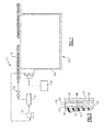
- FIG. 1 schematically illustrates a cooling system 10.
- the cooling system 10 includes a pump 12 providing a cooling fluid to a liquid to air heat exchanger 14.
- the cooled fluid flows through a flow metering orifice 16 to a cold plate 18 where it receives heat rejected from an electronic element 20 mounted to the cold plate 18.
- Fluid from the cold plate 18 returns to the pump 12.
- the electronic element 20 may be part of a motor controller that is electrically connected to a component 22, such as a motor.
- the electronic element 20 is an inductor arranged in an inductor housing 24.
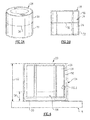
- the inductor housing 24 includes a core housing 28 providing a cavity 34 having a core 26 arranged within the cavity 34, which is illustrated in more detail in Figures 2A and 2B .
- the core housing 28 and core 26 provide an annular shape, although it should be understood that other shapes, such as double-C shapes, may be used.
- the core 26 may be constructed from material, such as a soft magnetic nanocrystalline material, for example, VITROPERM.
- the core housing 28 may be a plastic material, such as polyether ether ketone (PEEK).
- PEEK polyether ether ketone
- the first and second housing portions 30, 32 may be secured to one another in a suitable manner, such as welding at the portions to one another at a seam 36 to completely enclose and seal the cavity 34.
- a two-phase cooling fluid such as a fluorocarbon liquid (e.g., FC-72) fills at least a portion of the cavity 34.
- the cooling fluid includes both liquid and vapor phases during a normal operation of the electronic element, creating a heat pipe.
- the cavity 34 is only partially filled with the cooling fluid, such as 20-30% of the cavity volume.
- Wire windings 58 ( Figure 4 ) are wrapped about the core housing 28 to provide a toroidal shape.
- the wire wound core housing 28 is arranged in the inductor housing 24 to insulate the wire windings 58 from the surrounding environment.
- the core 26 and core housing 28 respectively provide first and second surfaces 38, 40 having a gap 43 between the surfaces.
- a wicking material 42 is arranged next to each of the first and second surfaces 38, 40 in spaced relationship relative to one another.
- the wicking material 42 may be a sintered metal, such as aluminum or copper.
- the wicking material 42 may include grooves, provide a mesh or may be micromachined.
- the wicking material 42 is secured to the first and second surfaces 38, 40.
- a bonding material, such as epoxy, may be used to adhere the wicking material 42 to the first and second surfaces 38, 40.
- the wicking material 42 may be diffusion-bonded to the first and second surface 38, 40, if desired. It should be understood that the wicking material 42 may be provided on only one of the surfaces or spaced from the surfaces.
- the liquid phase collects in the wicking material 42 and flows downward in the first direction 46 under gravity. As the condensed cooling fluid at the bottom of the cavity 34 heats, the vapor phase flows in the second direction 48. In this manner, the cooling fluid is continually recycled and no external means are needed for circulation of the cooling fluid within the core housing 28.
- the core housing 28 includes a base 50 that is operatively mounted to the cold plate 18.
- a potting material 54 encases only a portion of the core housing 28 in the example illustrated.
- the inductor housing 24 may enclose the core housing 28 and the potting material 54.
- the potting material 54 extends from the base 50 a distance 56 that is less than a height 52 of the core housing 28 and, in one example, less than one third of the height 52.
Landscapes
- Engineering & Computer Science (AREA)
- Microelectronics & Electronic Packaging (AREA)
- Physics & Mathematics (AREA)
- Thermal Sciences (AREA)
- Cooling Or The Like Of Electrical Apparatus (AREA)
- Cooling Or The Like Of Semiconductors Or Solid State Devices (AREA)
Abstract
Description
- This disclosure relates to an electronic component cooling arrangement. More particularly, the disclosure relates to using a two-phase fluid cooling arrangement to cool the electronic component.
- Devices, such as motor controllers for motors, typically include sophisticated electronic component assemblies made up of multiple electronic elements, which generate significant heat. This heat must be controlled sufficiently to prevent damage to the electronic elements. Typically, devices such as motor controllers are mounted on cooling plates arranged in a cooling loop filled with a cooling fluid. Increases in power dissipation density in magnetic assemblies require innovative thermal management in order to keep an inductor core and its winding, for example, within safe temperature limits. Expensive housing structure and potting compounds are used for thermal management. The potting material adds significant weight to the overall electronic components assembly.
- In one exemplary embodiment, an electronic component assembly includes a housing that provides a cavity filled with a cooling fluid that has a liquid phase and a vapor phase. An electronic element is arranged in the cavity and is configured to generate heat. A wicking material is arranged in the cavity between the housing and the electronic element. The cavity provides a gap adjacent to the wicking material. The wicking material is configured to absorb the liquid phase, and the vapor phase is provided in the gap.
- The disclosure can be further understood by reference to the following detailed description when considered in connection with the accompanying drawings wherein:
-
Figure 1 is a schematic view of a cooling system used to cool at least one electronic element of an electronic component assembly. -
Figures 2A and 2B are respectively perspective and side elevational views of a core housing. -
Figure 3 is an enlarged cross-sectional view of a portion of the electronic component assembly shown inFigure 4 . -
Figure 4 is a schematic view of the electronic element ofFigure 1 mounted to a cold plate. -
Figure 1 schematically illustrates acooling system 10. Thecooling system 10 includes apump 12 providing a cooling fluid to a liquid to air heat exchanger 14. The cooled fluid flows through aflow metering orifice 16 to acold plate 18 where it receives heat rejected from anelectronic element 20 mounted to thecold plate 18. Fluid from thecold plate 18 returns to thepump 12. Theelectronic element 20 may be part of a motor controller that is electrically connected to acomponent 22, such as a motor. - In one example, the
electronic element 20 is an inductor arranged in aninductor housing 24. Theinductor housing 24 includes acore housing 28 providing acavity 34 having acore 26 arranged within thecavity 34, which is illustrated in more detail inFigures 2A and 2B . In the example, thecore housing 28 andcore 26 provide an annular shape, although it should be understood that other shapes, such as double-C shapes, may be used. - The
core 26 may be constructed from material, such as a soft magnetic nanocrystalline material, for example, VITROPERM. Thecore housing 28 may be a plastic material, such as polyether ether ketone (PEEK). The first andsecond housing portions seam 36 to completely enclose and seal thecavity 34. - A two-phase cooling fluid, such as a fluorocarbon liquid (e.g., FC-72) fills at least a portion of the
cavity 34. The cooling fluid includes both liquid and vapor phases during a normal operation of the electronic element, creating a heat pipe. In one example, thecavity 34 is only partially filled with the cooling fluid, such as 20-30% of the cavity volume. - Wire windings 58 (
Figure 4 ) are wrapped about thecore housing 28 to provide a toroidal shape. The wire woundcore housing 28 is arranged in theinductor housing 24 to insulate thewire windings 58 from the surrounding environment. - Referring to
Figures 3 and4 , thecore 26 andcore housing 28 respectively provide first andsecond surfaces 38, 40 having agap 43 between the surfaces. In one example, awicking material 42 is arranged next to each of the first andsecond surfaces 38, 40 in spaced relationship relative to one another. In one example, thewicking material 42 may be a sintered metal, such as aluminum or copper. Thewicking material 42 may include grooves, provide a mesh or may be micromachined. In one example, thewicking material 42 is secured to the first andsecond surfaces 38, 40. A bonding material, such as epoxy, may be used to adhere the wickingmaterial 42 to the first andsecond surfaces 38, 40. Alternatively, thewicking material 42 may be diffusion-bonded to the first andsecond surface 38, 40, if desired. It should be understood that thewicking material 42 may be provided on only one of the surfaces or spaced from the surfaces. - As illustrated in
Figure 3 , the liquid phase collects in thewicking material 42 and flows downward in thefirst direction 46 under gravity. As the condensed cooling fluid at the bottom of thecavity 34 heats, the vapor phase flows in thesecond direction 48. In this manner, the cooling fluid is continually recycled and no external means are needed for circulation of the cooling fluid within thecore housing 28. - Returning to
Figure 4 , thecore housing 28 includes abase 50 that is operatively mounted to thecold plate 18. Apotting material 54 encases only a portion of thecore housing 28 in the example illustrated. Theinductor housing 24 may enclose thecore housing 28 and thepotting material 54. In one example, thepotting material 54 extends from the base 50 a distance 56 that is less than aheight 52 of thecore housing 28 and, in one example, less than one third of theheight 52. - Although an example embodiment has been disclosed, a worker of ordinary skill in this art would recognize that certain modifications would come within the scope of the claims. For that reason, the following claims should be studied to determine their true scope and content.
Claims (15)
- An electronic component assembly comprising:a housing (28) providing a cavity (34) filled with a cooling fluid having a liquid phase and a vapor phase;an electronic element (20) arranged in the cavity (28) and configured to generate heat; anda wicking material (42) arranged in the cavity between the housing and the electronic element (20), the cavity providing a gap adjacent to the wicking material, the wicking material configured to absorb the liquid phase, and the vapor phase is provided in the gap.
- The electronic component assembly according to claim 1, wherein the electronic element (20) includes a core (26) arranged in the housing (28), and a wire is wrapped about the core (26) to provide an inductor.
- The electronic component assembly according to claim 2, wherein the core (26) is annular in shape and the wire provides a toridal shape.
- The electronic component assembly according to claim 2, wherein the housing (28) is entirely sealed.
- The electronic component assembly according to claim 4, wherein the housing (28) is constructed from a plastic and includes first (30) and second (32) portions joined at a seam (36).
- The electronic component assembly according to any preceding claim, comprising a cold plate (18), wherein the housing includes a base operatively mounted to the cold plate.
- The electronic component assembly according to any preceding claim, comprising a cold plate (18), and further comprising a cooling loop including the cold plate.
- The electronic component assembly according to any preceding claim, wherein the wicking material (42) includes a sintered metal.
- The electronic component assembly according to claim 8, wherein the sintered metal is provided by at least one of aluminum or copper.
- The electronic component assembly according to any preceding claim, wherein the cooling fluid fills approximately 20-30% of the cavity, and/or wherein the cooling fluid is a fluorocarbon liquid.
- The electronic component assembly according to any preceding claim, wherein the wicking material (42) is secured to both the housing (28) and the electronic element (20), and the wicking material provides a gap (43).
- The electronic component assembly according to any preceding claim, wherein the liquid phase flows in a first direction and the vapor phase flows in a second direction opposite the first direction.
- The electronic component assembly according to any preceding claim, comprising a motor controller mounted to the cold plate, the motor controller including the inductor.
- The electronic component assembly according to any preceding claim, comprising a potting material (54) encasing a portion of the housing (28) less than a height (52) of the housing (28).
- The electronic component assembly according to any preceding claim, comprising a potting material (54), wherein the potting material (54) encases the housing (28) a distance of less than 1/3 the height (52) of the housing (28).
Applications Claiming Priority (1)
| Application Number | Priority Date | Filing Date | Title |
|---|---|---|---|
| US13/474,266 US9042097B2 (en) | 2012-05-17 | 2012-05-17 | Two-phase electronic component cooling arrangement |
Publications (3)
| Publication Number | Publication Date |
|---|---|
| EP2665351A2 true EP2665351A2 (en) | 2013-11-20 |
| EP2665351A3 EP2665351A3 (en) | 2016-10-05 |
| EP2665351B1 EP2665351B1 (en) | 2018-03-14 |
Family
ID=48463699
Family Applications (1)
| Application Number | Title | Priority Date | Filing Date |
|---|---|---|---|
| EP13166042.5A Active EP2665351B1 (en) | 2012-05-17 | 2013-04-30 | Two-phase electronic component cooling arrangement |
Country Status (2)
| Country | Link |
|---|---|
| US (1) | US9042097B2 (en) |
| EP (1) | EP2665351B1 (en) |
Families Citing this family (11)
| Publication number | Priority date | Publication date | Assignee | Title |
|---|---|---|---|---|
| US9854715B2 (en) | 2011-06-27 | 2017-12-26 | Ebullient, Inc. | Flexible two-phase cooling system |
| US9832913B2 (en) | 2011-06-27 | 2017-11-28 | Ebullient, Inc. | Method of operating a cooling apparatus to provide stable two-phase flow |
| US9901008B2 (en) | 2014-10-27 | 2018-02-20 | Ebullient, Inc. | Redundant heat sink module |
| US9901013B2 (en) | 2011-06-27 | 2018-02-20 | Ebullient, Inc. | Method of cooling series-connected heat sink modules |
| US9848509B2 (en) | 2011-06-27 | 2017-12-19 | Ebullient, Inc. | Heat sink module |
| US9854714B2 (en) | 2011-06-27 | 2017-12-26 | Ebullient, Inc. | Method of absorbing sensible and latent heat with series-connected heat sinks |
| US9852963B2 (en) | 2014-10-27 | 2017-12-26 | Ebullient, Inc. | Microprocessor assembly adapted for fluid cooling |
| US10184699B2 (en) | 2014-10-27 | 2019-01-22 | Ebullient, Inc. | Fluid distribution unit for two-phase cooling system |
| US20160120059A1 (en) | 2014-10-27 | 2016-04-28 | Ebullient, Llc | Two-phase cooling system |
| US9723753B2 (en) * | 2014-10-28 | 2017-08-01 | Hamilton Sundstrand Corporation | Planar heat cup with confined reservoir for electronic power component |
| CN104460909B (en) * | 2014-12-18 | 2018-05-18 | 山东超越数控电子有限公司 | A kind of gap automatic adjusument cold plate heat dissipating method |
Family Cites Families (25)
| Publication number | Priority date | Publication date | Assignee | Title |
|---|---|---|---|---|
| JP2865097B1 (en) * | 1997-09-11 | 1999-03-08 | 日本電気株式会社 | Multi-chip module cooling structure |
| US3714981A (en) * | 1971-02-03 | 1973-02-06 | Noren Prod Inc | Heat shield assembly |
| US4047198A (en) * | 1976-04-19 | 1977-09-06 | Hughes Aircraft Company | Transistor cooling by heat pipes having a wick of dielectric powder |
| GB1595094A (en) * | 1977-10-19 | 1981-08-05 | Gen Electric | Method and system for cooling electrical apparatus |
| US4212349A (en) * | 1979-01-02 | 1980-07-15 | International Business Machines Corporation | Micro bellows thermo capsule |
| US4671349A (en) * | 1985-03-18 | 1987-06-09 | Piero Wolk | Well logging electronics cooling system |
| US4944344A (en) | 1988-10-31 | 1990-07-31 | Sundstrand Corporation | Hermetically sealed modular electronic cold plate utilizing reflux cooling |
| US4947287A (en) | 1988-11-30 | 1990-08-07 | Sundstrand Corporation | Capacitor cooling arrangement |
| US4910642A (en) | 1988-12-05 | 1990-03-20 | Sundstrand Corporation | Coolant activated contact compact high intensity cooler |
| US4956626A (en) | 1989-01-13 | 1990-09-11 | Sundstrand Corporation | Inductor transformer cooling apparatus |
| US5088005A (en) | 1990-05-08 | 1992-02-11 | Sundstrand Corporation | Cold plate for cooling electronics |
| US6317321B1 (en) * | 1994-11-04 | 2001-11-13 | Compaq Computer Corporation | Lap-top enclosure having surface coated with heat-absorbing phase-change material |
| US5884693A (en) * | 1997-12-31 | 1999-03-23 | Dsc Telecom L.P. | Integral heat pipe enclosure |
| US7152667B2 (en) * | 2001-10-10 | 2006-12-26 | Fujikura Ltd. | Tower type finned heat pipe type heat sink |
| US6875966B1 (en) | 2004-03-15 | 2005-04-05 | Nexicor Llc | Portable induction heating tool for soldering pipes |
| US8124113B2 (en) | 2005-09-06 | 2012-02-28 | Hamilton Sundstrand Space Systems International, Inc. | Hydrophilic coating |
| US7602608B2 (en) | 2006-02-06 | 2009-10-13 | Isothermal Systems Research, Inc. | Narrow gap spray cooling in a globally cooled enclosure |
| US7495914B2 (en) | 2006-02-06 | 2009-02-24 | Isothermal Systems Research, Inc. | Narrow gap spray cooling in a globally cooled enclosure |
| US7369410B2 (en) * | 2006-05-03 | 2008-05-06 | International Business Machines Corporation | Apparatuses for dissipating heat from semiconductor devices |
| US7561425B2 (en) * | 2006-06-07 | 2009-07-14 | The Boeing Company | Encapsulated multi-phase electronics heat-sink |
| US8176972B2 (en) * | 2006-08-31 | 2012-05-15 | International Business Machines Corporation | Compliant vapor chamber chip packaging |
| US8284004B2 (en) * | 2006-11-29 | 2012-10-09 | Honeywell International Inc. | Heat pipe supplemented transformer cooling |
| US20090008063A1 (en) | 2007-07-03 | 2009-01-08 | Raytheon Company | System and Method for Passive Cooling Using a Non-Metallic Wick |
| TW201122396A (en) * | 2009-12-18 | 2011-07-01 | Ying-Tung Chen | ive micro-structure thereof. |
| JP4801797B1 (en) * | 2010-03-10 | 2011-10-26 | パナソニック株式会社 | Semiconductor device and manufacturing method thereof |
-
2012
- 2012-05-17 US US13/474,266 patent/US9042097B2/en active Active
-
2013
- 2013-04-30 EP EP13166042.5A patent/EP2665351B1/en active Active
Also Published As
| Publication number | Publication date |
|---|---|
| EP2665351A3 (en) | 2016-10-05 |
| US9042097B2 (en) | 2015-05-26 |
| EP2665351B1 (en) | 2018-03-14 |
| US20130308271A1 (en) | 2013-11-21 |
Similar Documents
| Publication | Publication Date | Title |
|---|---|---|
| US9042097B2 (en) | Two-phase electronic component cooling arrangement | |
| JP6848050B2 (en) | Electromechanical equipment | |
| KR101977452B1 (en) | Monolithic multi-module electronics chassis with multi-planar embedded fluid cooling channels | |
| TWI669725B (en) | Transformer-based power converters with 3d printed microchannel heat sink | |
| US9148984B2 (en) | High-power electromagnetic assembly | |
| US9466415B2 (en) | Reactor provided with a cooler | |
| US9373988B2 (en) | Assemblies and methods for cooling electric machines | |
| JP2010154713A (en) | Stator for motor and divided stator for motor | |
| US20180166757A1 (en) | Thermal management of energy storage devices via oscillating heat pipes | |
| EP3712913A1 (en) | Electric power converter | |
| US8289711B2 (en) | Integrated thermal packaging of high power motor controller | |
| US20180315681A1 (en) | Integrated circuit direct cooling systems and related methods | |
| JP2016139749A (en) | Power conversion device and manufacturing method therefor | |
| KR101114995B1 (en) | Compact transformer using heat exhaust means | |
| JP2017041497A (en) | Reactor | |
| EP2568484B1 (en) | Electro-magnetic device having a polymer housing | |
| JP5566418B2 (en) | Heating device with cooler | |
| CA3159142A1 (en) | Thermal ground plane | |
| EP2845293B1 (en) | Internally cooled servo motor with a segmented stator | |
| JP2020155455A (en) | Inductor device | |
| JP6398907B2 (en) | Reactor | |
| EP2618343A1 (en) | High-voltage-transformer |
Legal Events
| Date | Code | Title | Description |
|---|---|---|---|
| PUAI | Public reference made under article 153(3) epc to a published international application that has entered the european phase |
Free format text: ORIGINAL CODE: 0009012 |
|
| AK | Designated contracting states |
Kind code of ref document: A2 Designated state(s): AL AT BE BG CH CY CZ DE DK EE ES FI FR GB GR HR HU IE IS IT LI LT LU LV MC MK MT NL NO PL PT RO RS SE SI SK SM TR |
|
| AX | Request for extension of the european patent |
Extension state: BA ME |
|
| PUAL | Search report despatched |
Free format text: ORIGINAL CODE: 0009013 |
|
| RIC1 | Information provided on ipc code assigned before grant |
Ipc: H01L 23/427 20060101ALI20160825BHEP Ipc: H05K 7/20 20060101AFI20160825BHEP Ipc: H01L 23/473 20060101ALI20160825BHEP Ipc: H01F 27/18 20060101ALI20160825BHEP |
|
| AK | Designated contracting states |
Kind code of ref document: A3 Designated state(s): AL AT BE BG CH CY CZ DE DK EE ES FI FR GB GR HR HU IE IS IT LI LT LU LV MC MK MT NL NO PL PT RO RS SE SI SK SM TR |
|
| AX | Request for extension of the european patent |
Extension state: BA ME |
|
| RIC1 | Information provided on ipc code assigned before grant |
Ipc: H01L 23/427 20060101ALI20160829BHEP Ipc: H01L 23/473 20060101ALI20160829BHEP Ipc: H05K 7/20 20060101AFI20160829BHEP Ipc: H01F 27/18 20060101ALI20160829BHEP |
|
| STAA | Information on the status of an ep patent application or granted ep patent |
Free format text: STATUS: REQUEST FOR EXAMINATION WAS MADE |
|
| 17P | Request for examination filed |
Effective date: 20170403 |
|
| RBV | Designated contracting states (corrected) |
Designated state(s): AL AT BE BG CH CY CZ DE DK EE ES FI FR GB GR HR HU IE IS IT LI LT LU LV MC MK MT NL NO PL PT RO RS SE SI SK SM TR |
|
| GRAP | Despatch of communication of intention to grant a patent |
Free format text: ORIGINAL CODE: EPIDOSNIGR1 |
|
| STAA | Information on the status of an ep patent application or granted ep patent |
Free format text: STATUS: GRANT OF PATENT IS INTENDED |
|
| INTG | Intention to grant announced |
Effective date: 20171012 |
|
| GRAS | Grant fee paid |
Free format text: ORIGINAL CODE: EPIDOSNIGR3 |
|
| GRAA | (expected) grant |
Free format text: ORIGINAL CODE: 0009210 |
|
| STAA | Information on the status of an ep patent application or granted ep patent |
Free format text: STATUS: THE PATENT HAS BEEN GRANTED |
|
| AK | Designated contracting states |
Kind code of ref document: B1 Designated state(s): AL AT BE BG CH CY CZ DE DK EE ES FI FR GB GR HR HU IE IS IT LI LT LU LV MC MK MT NL NO PL PT RO RS SE SI SK SM TR |
|
| REG | Reference to a national code |
Ref country code: GB Ref legal event code: FG4D |
|
| REG | Reference to a national code |
Ref country code: CH Ref legal event code: EP Ref country code: AT Ref legal event code: REF Ref document number: 980063 Country of ref document: AT Kind code of ref document: T Effective date: 20180315 |
|
| REG | Reference to a national code |
Ref country code: IE Ref legal event code: FG4D |
|
| REG | Reference to a national code |
Ref country code: DE Ref legal event code: R096 Ref document number: 602013034338 Country of ref document: DE |
|
| REG | Reference to a national code |
Ref country code: FR Ref legal event code: PLFP Year of fee payment: 6 |
|
| REG | Reference to a national code |
Ref country code: NL Ref legal event code: MP Effective date: 20180314 |
|
| REG | Reference to a national code |
Ref country code: LT Ref legal event code: MG4D |
|
| PG25 | Lapsed in a contracting state [announced via postgrant information from national office to epo] |
Ref country code: FI Free format text: LAPSE BECAUSE OF FAILURE TO SUBMIT A TRANSLATION OF THE DESCRIPTION OR TO PAY THE FEE WITHIN THE PRESCRIBED TIME-LIMIT Effective date: 20180314 Ref country code: NO Free format text: LAPSE BECAUSE OF FAILURE TO SUBMIT A TRANSLATION OF THE DESCRIPTION OR TO PAY THE FEE WITHIN THE PRESCRIBED TIME-LIMIT Effective date: 20180614 Ref country code: ES Free format text: LAPSE BECAUSE OF FAILURE TO SUBMIT A TRANSLATION OF THE DESCRIPTION OR TO PAY THE FEE WITHIN THE PRESCRIBED TIME-LIMIT Effective date: 20180314 Ref country code: HR Free format text: LAPSE BECAUSE OF FAILURE TO SUBMIT A TRANSLATION OF THE DESCRIPTION OR TO PAY THE FEE WITHIN THE PRESCRIBED TIME-LIMIT Effective date: 20180314 Ref country code: LT Free format text: LAPSE BECAUSE OF FAILURE TO SUBMIT A TRANSLATION OF THE DESCRIPTION OR TO PAY THE FEE WITHIN THE PRESCRIBED TIME-LIMIT Effective date: 20180314 Ref country code: CY Free format text: LAPSE BECAUSE OF FAILURE TO SUBMIT A TRANSLATION OF THE DESCRIPTION OR TO PAY THE FEE WITHIN THE PRESCRIBED TIME-LIMIT Effective date: 20180314 |
|
| REG | Reference to a national code |
Ref country code: AT Ref legal event code: MK05 Ref document number: 980063 Country of ref document: AT Kind code of ref document: T Effective date: 20180314 |
|
| PG25 | Lapsed in a contracting state [announced via postgrant information from national office to epo] |
Ref country code: BG Free format text: LAPSE BECAUSE OF FAILURE TO SUBMIT A TRANSLATION OF THE DESCRIPTION OR TO PAY THE FEE WITHIN THE PRESCRIBED TIME-LIMIT Effective date: 20180614 Ref country code: GR Free format text: LAPSE BECAUSE OF FAILURE TO SUBMIT A TRANSLATION OF THE DESCRIPTION OR TO PAY THE FEE WITHIN THE PRESCRIBED TIME-LIMIT Effective date: 20180615 Ref country code: LV Free format text: LAPSE BECAUSE OF FAILURE TO SUBMIT A TRANSLATION OF THE DESCRIPTION OR TO PAY THE FEE WITHIN THE PRESCRIBED TIME-LIMIT Effective date: 20180314 Ref country code: SE Free format text: LAPSE BECAUSE OF FAILURE TO SUBMIT A TRANSLATION OF THE DESCRIPTION OR TO PAY THE FEE WITHIN THE PRESCRIBED TIME-LIMIT Effective date: 20180314 Ref country code: RS Free format text: LAPSE BECAUSE OF FAILURE TO SUBMIT A TRANSLATION OF THE DESCRIPTION OR TO PAY THE FEE WITHIN THE PRESCRIBED TIME-LIMIT Effective date: 20180314 |
|
| PG25 | Lapsed in a contracting state [announced via postgrant information from national office to epo] |
Ref country code: EE Free format text: LAPSE BECAUSE OF FAILURE TO SUBMIT A TRANSLATION OF THE DESCRIPTION OR TO PAY THE FEE WITHIN THE PRESCRIBED TIME-LIMIT Effective date: 20180314 Ref country code: PL Free format text: LAPSE BECAUSE OF FAILURE TO SUBMIT A TRANSLATION OF THE DESCRIPTION OR TO PAY THE FEE WITHIN THE PRESCRIBED TIME-LIMIT Effective date: 20180314 Ref country code: AL Free format text: LAPSE BECAUSE OF FAILURE TO SUBMIT A TRANSLATION OF THE DESCRIPTION OR TO PAY THE FEE WITHIN THE PRESCRIBED TIME-LIMIT Effective date: 20180314 Ref country code: IT Free format text: LAPSE BECAUSE OF FAILURE TO SUBMIT A TRANSLATION OF THE DESCRIPTION OR TO PAY THE FEE WITHIN THE PRESCRIBED TIME-LIMIT Effective date: 20180314 Ref country code: RO Free format text: LAPSE BECAUSE OF FAILURE TO SUBMIT A TRANSLATION OF THE DESCRIPTION OR TO PAY THE FEE WITHIN THE PRESCRIBED TIME-LIMIT Effective date: 20180314 Ref country code: NL Free format text: LAPSE BECAUSE OF FAILURE TO SUBMIT A TRANSLATION OF THE DESCRIPTION OR TO PAY THE FEE WITHIN THE PRESCRIBED TIME-LIMIT Effective date: 20180314 |
|
| PG25 | Lapsed in a contracting state [announced via postgrant information from national office to epo] |
Ref country code: CZ Free format text: LAPSE BECAUSE OF FAILURE TO SUBMIT A TRANSLATION OF THE DESCRIPTION OR TO PAY THE FEE WITHIN THE PRESCRIBED TIME-LIMIT Effective date: 20180314 Ref country code: SM Free format text: LAPSE BECAUSE OF FAILURE TO SUBMIT A TRANSLATION OF THE DESCRIPTION OR TO PAY THE FEE WITHIN THE PRESCRIBED TIME-LIMIT Effective date: 20180314 Ref country code: AT Free format text: LAPSE BECAUSE OF FAILURE TO SUBMIT A TRANSLATION OF THE DESCRIPTION OR TO PAY THE FEE WITHIN THE PRESCRIBED TIME-LIMIT Effective date: 20180314 Ref country code: SK Free format text: LAPSE BECAUSE OF FAILURE TO SUBMIT A TRANSLATION OF THE DESCRIPTION OR TO PAY THE FEE WITHIN THE PRESCRIBED TIME-LIMIT Effective date: 20180314 |
|
| REG | Reference to a national code |
Ref country code: CH Ref legal event code: PL |
|
| REG | Reference to a national code |
Ref country code: DE Ref legal event code: R097 Ref document number: 602013034338 Country of ref document: DE |
|
| REG | Reference to a national code |
Ref country code: BE Ref legal event code: MM Effective date: 20180430 |
|
| PG25 | Lapsed in a contracting state [announced via postgrant information from national office to epo] |
Ref country code: PT Free format text: LAPSE BECAUSE OF FAILURE TO SUBMIT A TRANSLATION OF THE DESCRIPTION OR TO PAY THE FEE WITHIN THE PRESCRIBED TIME-LIMIT Effective date: 20180716 |
|
| PLBE | No opposition filed within time limit |
Free format text: ORIGINAL CODE: 0009261 |
|
| STAA | Information on the status of an ep patent application or granted ep patent |
Free format text: STATUS: NO OPPOSITION FILED WITHIN TIME LIMIT |
|
| REG | Reference to a national code |
Ref country code: IE Ref legal event code: MM4A |
|
| PG25 | Lapsed in a contracting state [announced via postgrant information from national office to epo] |
Ref country code: DK Free format text: LAPSE BECAUSE OF FAILURE TO SUBMIT A TRANSLATION OF THE DESCRIPTION OR TO PAY THE FEE WITHIN THE PRESCRIBED TIME-LIMIT Effective date: 20180314 Ref country code: LU Free format text: LAPSE BECAUSE OF NON-PAYMENT OF DUE FEES Effective date: 20180430 Ref country code: MC Free format text: LAPSE BECAUSE OF FAILURE TO SUBMIT A TRANSLATION OF THE DESCRIPTION OR TO PAY THE FEE WITHIN THE PRESCRIBED TIME-LIMIT Effective date: 20180314 |
|
| 26N | No opposition filed |
Effective date: 20181217 |
|
| PG25 | Lapsed in a contracting state [announced via postgrant information from national office to epo] |
Ref country code: BE Free format text: LAPSE BECAUSE OF NON-PAYMENT OF DUE FEES Effective date: 20180430 Ref country code: LI Free format text: LAPSE BECAUSE OF NON-PAYMENT OF DUE FEES Effective date: 20180430 Ref country code: CH Free format text: LAPSE BECAUSE OF NON-PAYMENT OF DUE FEES Effective date: 20180430 Ref country code: SI Free format text: LAPSE BECAUSE OF FAILURE TO SUBMIT A TRANSLATION OF THE DESCRIPTION OR TO PAY THE FEE WITHIN THE PRESCRIBED TIME-LIMIT Effective date: 20180314 |
|
| PG25 | Lapsed in a contracting state [announced via postgrant information from national office to epo] |
Ref country code: IE Free format text: LAPSE BECAUSE OF NON-PAYMENT OF DUE FEES Effective date: 20180430 |
|
| PG25 | Lapsed in a contracting state [announced via postgrant information from national office to epo] |
Ref country code: MT Free format text: LAPSE BECAUSE OF NON-PAYMENT OF DUE FEES Effective date: 20180430 |
|
| PG25 | Lapsed in a contracting state [announced via postgrant information from national office to epo] |
Ref country code: TR Free format text: LAPSE BECAUSE OF FAILURE TO SUBMIT A TRANSLATION OF THE DESCRIPTION OR TO PAY THE FEE WITHIN THE PRESCRIBED TIME-LIMIT Effective date: 20180314 |
|
| PG25 | Lapsed in a contracting state [announced via postgrant information from national office to epo] |
Ref country code: HU Free format text: LAPSE BECAUSE OF FAILURE TO SUBMIT A TRANSLATION OF THE DESCRIPTION OR TO PAY THE FEE WITHIN THE PRESCRIBED TIME-LIMIT; INVALID AB INITIO Effective date: 20130430 |
|
| PG25 | Lapsed in a contracting state [announced via postgrant information from national office to epo] |
Ref country code: MK Free format text: LAPSE BECAUSE OF NON-PAYMENT OF DUE FEES Effective date: 20180314 |
|
| PG25 | Lapsed in a contracting state [announced via postgrant information from national office to epo] |
Ref country code: IS Free format text: LAPSE BECAUSE OF FAILURE TO SUBMIT A TRANSLATION OF THE DESCRIPTION OR TO PAY THE FEE WITHIN THE PRESCRIBED TIME-LIMIT Effective date: 20180714 |
|
| P01 | Opt-out of the competence of the unified patent court (upc) registered |
Effective date: 20230522 |
|
| PGFP | Annual fee paid to national office [announced via postgrant information from national office to epo] |
Ref country code: FR Payment date: 20250319 Year of fee payment: 13 |
|
| PGFP | Annual fee paid to national office [announced via postgrant information from national office to epo] |
Ref country code: GB Payment date: 20250319 Year of fee payment: 13 |
|
| PGFP | Annual fee paid to national office [announced via postgrant information from national office to epo] |
Ref country code: DE Payment date: 20250319 Year of fee payment: 13 |