EP2665207A1 - User Equipment and Method for Radio Link Monitoring - Google Patents
User Equipment and Method for Radio Link Monitoring Download PDFInfo
- Publication number
- EP2665207A1 EP2665207A1 EP12167981.5A EP12167981A EP2665207A1 EP 2665207 A1 EP2665207 A1 EP 2665207A1 EP 12167981 A EP12167981 A EP 12167981A EP 2665207 A1 EP2665207 A1 EP 2665207A1
- Authority
- EP
- European Patent Office
- Prior art keywords
- channel
- power
- user equipment
- noise
- signal
- Prior art date
- Legal status (The legal status is an assumption and is not a legal conclusion. Google has not performed a legal analysis and makes no representation as to the accuracy of the status listed.)
- Granted
Links
- 238000000034 method Methods 0.000 title claims abstract description 53
- 238000012544 monitoring process Methods 0.000 title claims abstract description 28
- 238000004364 calculation method Methods 0.000 claims abstract description 16
- 238000001514 detection method Methods 0.000 claims abstract description 14
- 238000004891 communication Methods 0.000 claims description 12
- 230000001419 dependent effect Effects 0.000 claims description 12
- 238000010586 diagram Methods 0.000 description 9
- 238000012935 Averaging Methods 0.000 description 8
- 230000005540 biological transmission Effects 0.000 description 8
- 238000013507 mapping Methods 0.000 description 6
- 238000012545 processing Methods 0.000 description 5
- 230000006870 function Effects 0.000 description 4
- 101100366000 Caenorhabditis elegans snr-1 gene Proteins 0.000 description 3
- 101100419874 Caenorhabditis elegans snr-2 gene Proteins 0.000 description 3
- 238000001914 filtration Methods 0.000 description 3
- 238000005259 measurement Methods 0.000 description 3
- 238000012937 correction Methods 0.000 description 2
- 238000001228 spectrum Methods 0.000 description 2
- 101100350187 Caenorhabditis elegans odd-2 gene Proteins 0.000 description 1
- 241000760358 Enodes Species 0.000 description 1
- 239000000654 additive Substances 0.000 description 1
- 230000000996 additive effect Effects 0.000 description 1
- 238000004458 analytical method Methods 0.000 description 1
- 238000013459 approach Methods 0.000 description 1
- 239000000969 carrier Substances 0.000 description 1
- 230000010267 cellular communication Effects 0.000 description 1
- 230000001427 coherent effect Effects 0.000 description 1
- 238000013500 data storage Methods 0.000 description 1
- 238000000354 decomposition reaction Methods 0.000 description 1
- 238000005516 engineering process Methods 0.000 description 1
- 238000011156 evaluation Methods 0.000 description 1
- 230000007774 longterm Effects 0.000 description 1
- 238000012986 modification Methods 0.000 description 1
- 230000004048 modification Effects 0.000 description 1
Images


Classifications
-
- H—ELECTRICITY
- H04—ELECTRIC COMMUNICATION TECHNIQUE
- H04L—TRANSMISSION OF DIGITAL INFORMATION, e.g. TELEGRAPHIC COMMUNICATION
- H04L25/00—Baseband systems
- H04L25/02—Details ; arrangements for supplying electrical power along data transmission lines
- H04L25/0202—Channel estimation
- H04L25/0224—Channel estimation using sounding signals
- H04L25/0228—Channel estimation using sounding signals with direct estimation from sounding signals
- H04L25/023—Channel estimation using sounding signals with direct estimation from sounding signals with extension to other symbols
- H04L25/0232—Channel estimation using sounding signals with direct estimation from sounding signals with extension to other symbols by interpolation between sounding signals
-
- H—ELECTRICITY
- H04—ELECTRIC COMMUNICATION TECHNIQUE
- H04B—TRANSMISSION
- H04B17/00—Monitoring; Testing
- H04B17/30—Monitoring; Testing of propagation channels
- H04B17/309—Measuring or estimating channel quality parameters
-
- H—ELECTRICITY
- H04—ELECTRIC COMMUNICATION TECHNIQUE
- H04B—TRANSMISSION
- H04B17/00—Monitoring; Testing
- H04B17/30—Monitoring; Testing of propagation channels
- H04B17/309—Measuring or estimating channel quality parameters
- H04B17/318—Received signal strength
- H04B17/327—Received signal code power [RSCP]
-
- H—ELECTRICITY
- H04—ELECTRIC COMMUNICATION TECHNIQUE
- H04B—TRANSMISSION
- H04B17/00—Monitoring; Testing
- H04B17/30—Monitoring; Testing of propagation channels
- H04B17/309—Measuring or estimating channel quality parameters
- H04B17/336—Signal-to-interference ratio [SIR] or carrier-to-interference ratio [CIR]
-
- H—ELECTRICITY
- H04—ELECTRIC COMMUNICATION TECHNIQUE
- H04B—TRANSMISSION
- H04B17/00—Monitoring; Testing
- H04B17/30—Monitoring; Testing of propagation channels
- H04B17/309—Measuring or estimating channel quality parameters
- H04B17/345—Interference values
-
- H—ELECTRICITY
- H04—ELECTRIC COMMUNICATION TECHNIQUE
- H04L—TRANSMISSION OF DIGITAL INFORMATION, e.g. TELEGRAPHIC COMMUNICATION
- H04L5/00—Arrangements affording multiple use of the transmission path
- H04L5/0001—Arrangements for dividing the transmission path
- H04L5/0003—Two-dimensional division
- H04L5/0005—Time-frequency
Definitions
- the present disclosure relates to wireless communication devices and more particularly to techniques aimed at reducing the complexity of the processing required for the estimation of the downlink radio link quality of the serving cell.
- LTE Long Term Evolution
- GSM Global System for Mobile Communications
- UMTS Universal Mobile Communications
- DSP Digital Signal Processing
- the LTE wireless interface is incompatible with second generation (2G) and third generation (3G) networks, and operates via a separate wireless spectrum.
- the Radio Link Monitoring (RLM) function implemented in the mobile subscriber's user equipment (UE) is to monitor the downlink radio link quality of the serving cell in RRC_CONNECTED state and is based on cell specific reference signals (RSs). This in turn enables the UE when in RRC_CONNECTED state to determine whether it is in-sync or out-of-sync with respect to its serving cell.
- RSs cell specific reference signals
- the UE After a certain number of consecutive out-of-sync indications, the UE starts a network configured radio link failure timer. The timer is stopped if a number of consecutive in-sync indications are reported by the UE's physical layer. Both the out-of-sync and in-sync timers are configurable by the network. If the out-of-sync timer expires, Radio Link Failure (RLF) is declared. The UE turns off its transmitter to avoid interference and save power, and is also required to re-establish the RRC connection within a certain time.
- RLF Radio Link Failure
- Control information is provided by the base-station to the UE through the Physical Downlink Control Channel (PDCCH).
- the PDCCH can be used by the base-station to indicate to the UE that information needs to be received in the downlink. This channel can also be used to send uplink grant messages to signal to the UE that it is allowed to transmit. More generally, the PDCCH is used by the base station to convey scheduling decisions to the UE and hence correct reception and decoding by the UE of the associated control messages is critical to the correct operation of the network. The criteria for indicating out-of-sync and in-sync conditions are therefore based on whether the UE can reliably decode the PDCCH or not.
- a number of different formats can be used for the transmission of the control information messages on the PDCCH in order to adapt to variations in the quality of the transmission link between the base-station and the UE.
- These different formats correspond to different levels of error correction redundancy and hence have different signal to noise ratio (SNR) requirements.
- SNR signal to noise ratio
- An out-of-sync indication will be generated when a hypothetical PDCCH transmitted with a format using a high level of redundancy cannot be received reliably by the UE.
- an in-sync indication will be generated.
- the generation of in-sync and out-of-sync indications requires the UE to estimate the Block Error Rate (BLER) for these two hypothetical formats.
- BLER Block Error Rate
- the existing BLER estimation solutions are based on calculating the effective SNR over the complete bandwidth on a per subcarrier basis.
- the SNR is generated from the channel estimation process performed on the Reference Signals (RSs) transmitted by the base station.
- RSs Reference Signals
- the ensemble of SNRs per subcarrier are mapped to an overall effective SNR using estimation methods such as mean mutual information per bit (MMIB) or exponential effective SNR mapping (EESM).
- MMIB mean mutual information per bit
- EESM exponential effective SNR mapping
- the operating points for the detection of out-of-sync and in-sync correspond to cases of very low signal-to-noise conditions that are very challenging for channel estimation and the high noise level in the received signal has a major impact on the accuracy of the calculated SNR per subcarrier.
- the channel estimation noise in these cases is high and adds to the average channel power leading to a bias in the calculated SNR.
- the channel estimation noise and the resulting channel power bias make the effective SNR highly unreliable when the number of available measurements is limited, for example when Discontinuous Reception (DRX) is used or in Time Division Duplex (TDD) mode when the number of downlink subframes is small.
- DRX Discontinuous Reception
- TDD Time Division Duplex
- the invention described therein provides techniques which improve the accuracy of the SNR estimation process and reduce the complexity of the radio link monitoring processing.
- radio link quality monitoring method and user equipment such that a given UE device receives a plurality of Orthogonal Frequency Division Multiplex (OFDM) symbols that comprise a plurality of Resource Elements (RE) distributed in time and frequency, and which include known reference symbols.
- the objective of the radio link quality monitoring is to predict the UE detection probability of control information messages that can be transmitted by the base station (BS).
- the radio link quality estimation process calculates two average signal to noise ratio values over the complete frequency bandwidth for two assumed control channel formats corresponding to in-sync and out-of-sync conditions. The results of the calculations are then used to deduce the average error probabilities that are compared with predefined thresholds to provide the in-sync/out-of-sync indications.
- the propagation channel estimates are generated for each RE and correspond to the different links between the multiple BS transmit antennas and the UE receive antennas.
- the UE also uses the reference symbols to estimate the noise power for each RE at each receive antenna.
- the channel estimates are then combined across multiple REs in order to generate a single channel power estimate for each of the propagation links. Similarly a single noise power estimate per receive antenna is generated.
- the UE removes the bias from the channel power estimate by taking into account the noise rejection provided by the channel estimation process.
- the unbiased channel power estimates and the noise power estimates are then used by the UE to estimate the SNR that would be experienced at the output of the demodulator for each configuration in a set of two control information message formats.
- the BLER based on the estimated SNR value, is calculated by the UE using the BLER versus SNR characteristics of the control channel demodulator in the absence of channel estimation errors for each of the two control information message formats.
- the UE then averages the BLER for the two assumed control channel formats by combining the BLER instances calculated for each of the formats over defined averaging periods.
- the averaged BLER for the two assumed control channel formats are then compared with optimised thresholds to provide out-of-sync and in-sync indications that are then passed to higher layers.
- the threshold used for the detection of out-of-sync is nominally set for a BLER of higher than 10%, while the threshold used for in-sync detection is nominally set for a BLER of lower than 2%.
- the signal power and the signal noise power are calculated with a power scaling parameter that is dependent on possible formats of the control messages. Additionally or alternatively the thresholds are dependent on the frequency bandwidth of the signals transmitted by the base station.
- different channel estimation processes are applied, on the one hand, to the channel estimates used for channel and noise power estimation and, on the other hand, for demodulation of the received signal.
- the SNR estimation is then adapted to reflect the difference in the noise rejection provided for the two different channel estimation processes.
- the channel power estimation, and the calculation of the SNR at the output of the demodulator can be adapted for use in different space/time encoding and demodulation techniques.
- different numbers of samples of the channel and noise power estimates can be used, after decimation, for radio link quality monitoring.
- the selection of the channel estimation samples used for radio link monitoring can be made to vary with the bandwidth of the signal received by the UE.
- the accuracy of the SNR estimation performed for radio link monitoring depends on the quality of the channel estimation samples which are used.
- the number of channel estimation samples used for radio link monitoring is made dependent on the noise rejection achieved by the channel estimation process.
- the ultimate problems to be solved are to address the low quality of the SNR estimates, as well as the impact of the high channel estimation errors at the demodulator.
- the SNR estimation is addressed by averaging the channel and noise power estimates over essentially the entire frequency bandwidth and removing the bias introduced by the noise from the channel power estimate.
- the impact of the high channel estimation errors at the demodulator is taken into account in the calculation of the SNR at the output of the demodulator using knowledge of the noise rejection of the channel estimation process
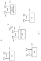
- FIG. 1 is an example of a block diagram of a wireless communication system in which a BS communicates with mobile stations (MSs), also referred to herein as UEs, in which each mobile station employs a Radio Link Monitoring process according to the techniques described herein.
- MSs mobile stations
- UEs mobile stations
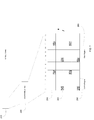
- FIG. 2 is an example block diagram of an LTE downlink transmission frame structure depicting the selected resource element groups that form the cell specific reference signals.
- FIG. 3 is an example block diagram of the overall architecture of the components implementing the processes described herein.
- FIG. 4 is an example block diagram of the RLM components depicting the detection processing according to the techniques described herein.
- FIG. 5 is an example block diagram of a UE that implements the RLM process according to the techniques described herein
- a wireless radio communication system or network is shown generally at reference numeral 100 and comprises a base station 110, or eNode B in LTE parlance, and a plurality of UEs or MSs 120(1)-120(Z).
- the BS 110 may connect to other wired data network facilities (not shown) and in that sense serves as a gateway or access point through which the MSs 120(1)-120(Z) have access to those data network facilities.
- the BS 110 comprises a plurality of antennas 140(1)-140(M) and the MSs 120(1)-120(Z) may also comprise a plurality of antennas 130(1)-130(N).
- the BS 110 may wirelessly communicate with individual ones of the MSs 120(1)-120(Z) using a wideband wireless communication protocol in which the bandwidth is much larger than the coherent frequency bandwidth, e.g., using LTE.
- the BS 100 transmits a combination of downlink control messages and reference signals 150.
- the downlink control messages are also referred to as Downlink Control Information (DCI) and are transmitted using PDCCHs.
- DCI Downlink Control Information
- the techniques provided herein enable the MSs on a wireless communication link to monitor the signal quality of these messages received from the BS using an RLM process.
- the BS 110 also transmits cell specific reference signal 150 to all the MSs 120(1)-120(Z).
- the MSs 120(1)-120(Z) monitor the signal quality of the reference signals they receive from the BS using the techniques described herein in order to estimate the reliability of the reception and decoding of the control messages.
- FIG. 2 shows an LTE frame 210 that is 10 milliseconds (ms) in duration.
- the frame 210 comprises 10 subframes that are 1 ms in duration, of which subframe 220 is shown.
- Subframe 220 comprises either 12 or 14 OFDM symbols that are, for example, part of an Orthogonal Frequency Division Multiple Access (OFDMA) transmission scheme.
- OFDMA divides the allocated radio frequency (RF) spectrum into a number of orthogonal subcarriers. In this example, 14 symbols numbered zero to 13 are shown with radio frequency (RF) f for individual subcarriers increasing from the bottom of the symbols toward the top of the symbols.
- RF radio frequency
- a resource element occupies a single subcarrier over one OFDM symbol.
- the symbols are divided into a control region 250 and a data region 260.
- the control region 250 may comprise the first one to four symbols, while the remainder of the symbols comprise the data region 260.
- the control region 250 comprises the first three symbols, numbered 0, 1, and 2.
- the cell specific reference signals 240 are dispersed throughout the symbol space as shown by the shaded areas.
- the time and frequency location of these reference signals in the subframe is known to the UE a-priori.
- the set of modulation symbols used by the reference signals are also known by the UE. This makes it possible for the UE to estimate the propagation channels using these reference signals.
- the unshaded divisions 230 of the control area 250 contain the PDCCH control information.
- FIG 3 an example block diagram is shown of the components of the received signal path.
- the received signals output from the front end transceiver 510, 520 are input to the Digital Baseband 300 ADC 310 which converts the Orthogonal Frequency Division Multiplex (OFDM) channels into digital data streams, one for each sub-carrier. Further processing is performed by the Fast Fourier Transform (FFT) 320 and the demodulator 330, wherein the demodulator 330 demodulates the FFT output signal and thus retrieves the control messages and other data included in the combination of downlink control messages and reference signals 150 transmitted by the base station BS.
- FFT Fast Fourier Transform
- the channel estimation module 340 uses the cell specific reference signal symbols to estimate the propagation channels corresponding to the multiple links between the different eNode-B and UE antennas.
- the estimation is performed by way of filtering and interpolation of the RS receive signal over the frequency and time domains (see FIG.2 ) [ P. Hoeher et al., "Two-dimensional pilot-symbol-aided channel estimation by wiener filtering", ICASSP, 1997 ] [ O. Edfors et al., "OFDM channel estimation by singular value decomposition", IEEE Trans. On Communications ].
- a single transmit antenna at the eNode-B i.e.
- the estimated channel samples are available for each of the subcarriers, with high resolution in time. However, for the purpose of Radio Link Monitoring not all channel samples are needed, therefore to save complexity only a limited subset of the samples are processed.
- the Radio Link Monitoring module 400 performs the RLM process which calculates the two average SNR values over the complete/entire frequency bandwidth for the two hypothetical PDCCH formats (i.e., possible control message formats) corresponding to in-sync and out-of-sync conditions. The results of the calculations are then used to deduce the average error probabilities that are compared with the out-of-sync and in-sync thresholds to provide the in-sync/out-of-sync detection.
- the average channel power per receive antenna is calculated from the post FFT channel estimate at 410.
- the channel estimates h l,r r are based on the RS symbols, however each of the two DCI transport formats (control message formats) has a different PDCCH to RS power ratio. These two power ratios are taken into account in the average SNRs.
- the channel power is averaged over the entire bandwidth and summed separately per receive antenna.
- the channel estimation samples h ⁇ l,r used in the calculation of the average channel power are selected from the set of channel estimates h l,r so as to essentially cover the entire bandwidth of the received signal.
- the selection of the channel samples used for RLM can be achieved by way of decimation of the channel samples available at the output of the channel estimation block.
- the decimation factor in this case can be made dependent on the bandwidth size and the number of transmit antennas, For example, the decimation factor could be adjusted in such a way that the total number of channel samples used for RLM is constant across different configurations such that a fixed complexity is achieved by the UE.
- the selection of the channel samples used for RLM can also be made dependent on the accuracy of the channel estimation process.
- the quality of the samples generated by the channel estimation module 340 usually depends on statistical characteristics of the propagation link, such as Doppler and delay spread.
- the amount of filtering, used both in the time and frequency domains, for the generation of the channel estimates will be set to match these channel parameters and hence the noise rejection achieved during the channel estimation will vary with these characteristics.
- the number of channel estimation samples used for RLM is therefore determined according to these statistical characteristics of the propagation channel.
- the number of samples is derived directly from the value of the noise rejection achieved by the channel estimation process.
- Some channel estimation techniques can lead to a poorer accuracy for the estimates corresponding to subcarriers at the edge of the received signal bandwidth.
- the channel estimates located close to DC may also be less accurate as the DC subcarrier isn't used for transmission by the base-station. It is possible to modify the above equation to take into account this variation in the quality of the different channel estimates. For example, the averaging process could be modified to ignore channel estimates corresponding to subcarriers close to the edge of the received signal bandwidth and/or close to the DC subcarrier. Alternatively, a weighted averaging could be used by using weights which are indicative of the quality of the channel estimates.
- the average noise power per receive antenna is calculated from the post-FFT channel noise power estimate ⁇ v , ⁇ , l 2 in the channel estimation module 340; where r is the receive antenna index and 1 is the sample index.
- the per receive antenna channel noise power is used to scale the averaged channel power. In the case of a different channel noise power estimate per subcarrier or group of subcarriers, the channel noise power can be averaged over the entire bandwidth to improve the noise power estimate accuracy.
- the techniques described above aimed to improving the quality of the channel power values by taking into the accuracy of the channel estimates can easily be extended to the channel noise power estimates.
- the channel estimate is assumed to have no multiplicative bias, i.e. the channel estimation has no impact on the scaling of the channel. If this is not the case, the multiplicative bias can be removed by scaling back the channel power and the channel noise power. Furthermore, if the subcarriers at the edge of the band are processed differently, which may lead to a different multiplication bias, this bias can be removed as well in order to ensure best performance.
- a normalize and bias removal module 430 is shown receiving the output signals from the channel estimation module 340, which are the signals as mentioned above (the average channel power per antenna and the average channel noise power per antenna). At 430 the bias due to the additive estimate errors is removed from the average channel power by subtracting the channel noise power contribution per receive antenna.
- the noise rejection gain which is the inverse of the channel estimation gain of the channel estimate used for RLM, is required to scale the noise power contribution.
- Noise rejection depends on the amount of channel averaging in the time/frequency domain, and of the density of the reference signal symbols.
- the bias is removed after the channel power is normalised by the channel noise power per receive antenna.
- the channel estimation gain G c is a measure of the noise reduction which is achieved by the channel estimation process.
- the + symbol means that negative values within the brackets should be treated as 0, while positive values remain unchanged.
- An unbiased normalised channel power across the receive antennas could equally be achieved by first removing the bias from the channel power and then scaling with respect to the channel noise power per receive antenna.
- the solution for calculating the unbiased channel power estimate per receive antenna above is dependent on the transmit antenna modulation used by the LTE system. However the solution can be adapted for other systems using different space/time encoding.
- the time averaging of the channel estimate used for RLM can be reduced from 1 subframe down to 1 slot or less in the case where no data transmission is scheduled to the UE. As a consequence there is less noise rejection and the channel bias to be removed is higher (scales inversely to the number of RS symbols used for channel estimation averaging in the time domain).
- Radio link monitoring module 400 further comprises a signal to noise calculation unit 440.
- the impact of the noise estimation error is taken into account by calculating the overall signal noise power experienced by the demodulator 330, which is the contribution of the channel noise power plus the contribution of the channel estimate errors power.
- the SNR calculation unit 440 Based on the output signals from the normalize and bias removal module 430 the SNR calculation unit 440 provides an predicted value or estimated value or representation for the signal power and signal noise power to be expected at the output of the demodulator 330 based on the FFT signal output at FFT module 330 and further processed by the channel estimation module 340 and the normalize and bias removal module 430.
- the signal power and the overall signal noise power are calculated using formulas based on the analysis of the maximal-ratio combining (MRC) demodulator, taking into account the channel estimation errors.
- MRC maximal-ratio combining
- the noise power rejection for demodulation is required to calculate the overall signal noise power at the demodulator. This can be different from the channel estimate that is used for the RLM where the channel estimates can be of different quality, for example, if the channel estimates are generated at different times.
- G 1 and G 2 are the channel estimation gains for transmitter antennas 1 and 2 respectively.
- P s x , even , P n x , even correspond to the demodulation signal powers and signal noise powers of the PDCCH even indexed symbols and which are transmitted on the antennas 1 and 3.
- P s x , odd , P n x , odd correspond to the demodulation signal powers and signal noise powers of the PDCCH odd indexed symbols and which are transmitted on antennas 2, and 4.
- the radio link monitoring module 400 further comprises a signal to noise ratio calculation unit, where at 440 two average SNRs are calculated for each of the hypothetical PDCCH transport formats defined for in-sync and out-of-sync detection later. The difference is the RS to PDCCH power scaling ( ⁇ ).
- the final result is obtained by averaging the signal power and signal noise power separately and then calculating the SNR as a ratio of the averages.
- EESM or MMIB for mapping odd and even instances into a single SNR is, in this case, different to the prior art solution where the EESM /MMIB map the full bandwidth into a single SNR.
- the estimated BLER based on the BLER versus SNR characteristic for a demodulator with no channel estimation errors, is evaluated for each of the two hypothetical PDCCH transport formats.
- the BLER is averaged over several measurement intervals as specified in 3GPP TS 36.133 Section 7.6.
- the BLER versus SNR characteristic is the same for all transmit antenna settings but is different for different channel bandwidths.
- out-of-sync and in-sync detection are performed by comparing the averaged BLERs, for DCI formats 1 and 2, with optimised thresholds.
- the out-of-sync threshold and the in-sync threshold are designed to yield best operating performance for the network.
- the threshold used for the detection of out-of-sync should nominally be set such that an indication is raised when the BLER for the first format is larger than 10%.
- the threshold used for in-sync detection should nominally be set such that an indication is raised for conditions where the BLER for the second format is lower than 2%.
- the thresholds may be adjusted according to the bandwidth of the received signal and possibly on the number of transmit antennas as well.
- Out-of-sync and in-sync detection can be expressed as: Q ⁇ m out > Thrd out : Out - of - Sync Q ⁇ m in ⁇ Thrd in : In - Sync
- in-sync and out-of-sync indications are passed to the higher layers as specified in 3GPP TS 36.133 Section 7.6.
- FIG. 5 an example block diagram is shown of a wireless communication device that may serve as MS 120(1) from FIG. 1 for the purpose of describing the RLM process techniques described above.
- FIG. 5 depicts MS 120(1) as an example of a wireless communication device that is configured to perform the RLM process.
- the wireless communication device MS 120(1) comprises a transmitter 510, a receiver 520, and a controller 530.
- the controller 530 supplies the data to the transmitter 510 to be transmitted and processes signals received by the receiver 520.
- the controller 530 performs other transmit and receive control functionality.
- Part of the functions of the transmitter 510 and receiver 520 may be implemented in a modem and other parts of the transmitter 510 and receiver 520 may be implemented in radio transmitter and radio transceiver circuits.
- ADCs analog-to-digital converters
- DACs digital-to-analog converters
- the transmitter 510 may comprise individual transmitter circuits that supply respective upconverted signals to corresponding ones of a plurality of antennas 130(1)-130(N) for transmission.
- the receiver 520 comprises a detector for detecting the signals received at each of the antennas 130(1)-130(N) and supplies corresponding detected data, e.g., LLR data, to the controller 530. It is understood that the receiver 520 may comprise a plurality of receiver circuits, each for a corresponding one of a plurality of antennas 130(1)-130(N). For simplicity, these individual receiver circuits are not shown.
- the controller 530 comprises a memory 540 or other data storage block that stores data used for the techniques described herein. The memory 540 may be separate or part of the controller 530. Instructions for performing channel estimation and the RLM process in the channel estimation module 340 and radio link monitoring module 400 may be stored in the memory 540 for execution by the controller 530.
- controller 530 may be implemented by logic encoded in one or more tangible (non-transitory) media (e.g., embedded logic such as an application specific integrated circuit, digital signal processor instructions, software that is executed by a processor, etc.), wherein the memory 540 stores data used for the computations described herein (and/or to store software or processor instructions that are executed to carry out the computations described herein).
- channel estimation module 340 and the RLM module 400 may be implemented with fixed logic or programmable logic (e.g., software/computer instructions executed by a processor).
Abstract
Description
- The present disclosure relates to wireless communication devices and more particularly to techniques aimed at reducing the complexity of the processing required for the estimation of the downlink radio link quality of the serving cell.
- The 3rd Generation Partnership Project (3GPP) developed the standards used by Long Term Evolution (LTE) cellular communication systems. LTE is a standard for wireless data communications technology that has evolved from the GSM/UMTS standards. The goal of LTE is to increase the capacity and speed of wireless data networks using new Digital Signal Processing (DSP) techniques and modulation schemes that were developed in the past decade. The LTE wireless interface is incompatible with second generation (2G) and third generation (3G) networks, and operates via a separate wireless spectrum.
- In LTE the purpose of the Radio Link Monitoring (RLM) function implemented in the mobile subscriber's user equipment (UE) is to monitor the downlink radio link quality of the serving cell in RRC_CONNECTED state and is based on cell specific reference signals (RSs). This in turn enables the UE when in RRC_CONNECTED state to determine whether it is in-sync or out-of-sync with respect to its serving cell.
- After a certain number of consecutive out-of-sync indications, the UE starts a network configured radio link failure timer. The timer is stopped if a number of consecutive in-sync indications are reported by the UE's physical layer. Both the out-of-sync and in-sync timers are configurable by the network. If the out-of-sync timer expires, Radio Link Failure (RLF) is declared. The UE turns off its transmitter to avoid interference and save power, and is also required to re-establish the RRC connection within a certain time.
- Control information is provided by the base-station to the UE through the Physical Downlink Control Channel (PDCCH). The PDCCH can be used by the base-station to indicate to the UE that information needs to be received in the downlink. This channel can also be used to send uplink grant messages to signal to the UE that it is allowed to transmit. More generally, the PDCCH is used by the base station to convey scheduling decisions to the UE and hence correct reception and decoding by the UE of the associated control messages is critical to the correct operation of the network. The criteria for indicating out-of-sync and in-sync conditions are therefore based on whether the UE can reliably decode the PDCCH or not.
- A number of different formats can be used for the transmission of the control information messages on the PDCCH in order to adapt to variations in the quality of the transmission link between the base-station and the UE. These different formats correspond to different levels of error correction redundancy and hence have different signal to noise ratio (SNR) requirements. An out-of-sync indication will be generated when a hypothetical PDCCH transmitted with a format using a high level of redundancy cannot be received reliably by the UE. On the other hand, if the UE estimates that it can correctly receive control messages transmitted on the PDCCH with a format using a low level of error correction redundancy, an in-sync indication will be generated. Hence, the generation of in-sync and out-of-sync indications requires the UE to estimate the Block Error Rate (BLER) for these two hypothetical formats.
- The existing BLER estimation solutions are based on calculating the effective SNR over the complete bandwidth on a per subcarrier basis. The SNR is generated from the channel estimation process performed on the Reference Signals (RSs) transmitted by the base station. The ensemble of SNRs per subcarrier are mapped to an overall effective SNR using estimation methods such as mean mutual information per bit (MMIB) or exponential effective SNR mapping (EESM). This effective SNR is then used to estimate the BLER, based on the BLER versus SNR mapping function for the assumed PDCCH transport format (see for example 3GPP R4-081998 and 3GPP R4-082302).
- The operating points for the detection of out-of-sync and in-sync correspond to cases of very low signal-to-noise conditions that are very challenging for channel estimation and the high noise level in the received signal has a major impact on the accuracy of the calculated SNR per subcarrier. The channel estimation noise in these cases is high and adds to the average channel power leading to a bias in the calculated SNR. The channel estimation noise and the resulting channel power bias make the effective SNR highly unreliable when the number of available measurements is limited, for example when Discontinuous Reception (DRX) is used or in Time Division Duplex (TDD) mode when the number of downlink subframes is small. The invention described therein provides techniques which improve the accuracy of the SNR estimation process and reduce the complexity of the radio link monitoring processing.
- The invention is defined in
claims - Techniques are provided herein, for radio link quality monitoring method and user equipment (UE), such that a given UE device receives a plurality of Orthogonal Frequency Division Multiplex (OFDM) symbols that comprise a plurality of Resource Elements (RE) distributed in time and frequency, and which include known reference symbols. The objective of the radio link quality monitoring is to predict the UE detection probability of control information messages that can be transmitted by the base station (BS). Preferably the radio link quality estimation process calculates two average signal to noise ratio values over the complete frequency bandwidth for two assumed control channel formats corresponding to in-sync and out-of-sync conditions. The results of the calculations are then used to deduce the average error probabilities that are compared with predefined thresholds to provide the in-sync/out-of-sync indications.
- Techniques are provided for the generation by the UE of propagation channel estimates using the known reference symbols. The propagation channel estimates are generated for each RE and correspond to the different links between the multiple BS transmit antennas and the UE receive antennas. The UE also uses the reference symbols to estimate the noise power for each RE at each receive antenna. The channel estimates are then combined across multiple REs in order to generate a single channel power estimate for each of the propagation links. Similarly a single noise power estimate per receive antenna is generated.
- The UE removes the bias from the channel power estimate by taking into account the noise rejection provided by the channel estimation process. The unbiased channel power estimates and the noise power estimates are then used by the UE to estimate the SNR that would be experienced at the output of the demodulator for each configuration in a set of two control information message formats.
- The BLER, based on the estimated SNR value, is calculated by the UE using the BLER versus SNR characteristics of the control channel demodulator in the absence of channel estimation errors for each of the two control information message formats. The UE then averages the BLER for the two assumed control channel formats by combining the BLER instances calculated for each of the formats over defined averaging periods.
- The averaged BLER for the two assumed control channel formats are then compared with optimised thresholds to provide out-of-sync and in-sync indications that are then passed to higher layers. The threshold used for the detection of out-of-sync is nominally set for a BLER of higher than 10%, while the threshold used for in-sync detection is nominally set for a BLER of lower than 2%.
- According to an embodiment the signal power and the signal noise power are calculated with a power scaling parameter that is dependent on possible formats of the control messages. Additionally or alternatively the thresholds are dependent on the frequency bandwidth of the signals transmitted by the base station.
- According to one further aspect of the invention, different channel estimation processes are applied, on the one hand, to the channel estimates used for channel and noise power estimation and, on the other hand, for demodulation of the received signal. The SNR estimation is then adapted to reflect the difference in the noise rejection provided for the two different channel estimation processes. In the case of the use of multiple transmit antennas, the channel power estimation, and the calculation of the SNR at the output of the demodulator, can be adapted for use in different space/time encoding and demodulation techniques.
- According to one further aspect of the invention, different numbers of samples of the channel and noise power estimates can be used, after decimation, for radio link quality monitoring. The selection of the channel estimation samples used for radio link monitoring can be made to vary with the bandwidth of the signal received by the UE. The accuracy of the SNR estimation performed for radio link monitoring depends on the quality of the channel estimation samples which are used. Hence, according to one further aspect of the invention, the number of channel estimation samples used for radio link monitoring is made dependent on the noise rejection achieved by the channel estimation process.
- The ultimate problems to be solved are to address the low quality of the SNR estimates, as well as the impact of the high channel estimation errors at the demodulator. The SNR estimation is addressed by averaging the channel and noise power estimates over essentially the entire frequency bandwidth and removing the bias introduced by the noise from the channel power estimate. The impact of the high channel estimation errors at the demodulator is taken into account in the calculation of the SNR at the output of the demodulator using knowledge of the noise rejection of the channel estimation process
-
FIG. 1 is an example of a block diagram of a wireless communication system in which a BS communicates with mobile stations (MSs), also referred to herein as UEs, in which each mobile station employs a Radio Link Monitoring process according to the techniques described herein. -
FIG. 2 is an example block diagram of an LTE downlink transmission frame structure depicting the selected resource element groups that form the cell specific reference signals. -
FIG. 3 is an example block diagram of the overall architecture of the components implementing the processes described herein. -
FIG. 4 is an example block diagram of the RLM components depicting the detection processing according to the techniques described herein. -
FIG. 5 is an example block diagram of a UE that implements the RLM process according to the techniques described herein - Referring first to
FIG. 1 , a wireless radio communication system or network is shown generally atreference numeral 100 and comprises abase station 110, or eNode B in LTE parlance, and a plurality of UEs or MSs 120(1)-120(Z). TheBS 110 may connect to other wired data network facilities (not shown) and in that sense serves as a gateway or access point through which the MSs 120(1)-120(Z) have access to those data network facilities. - The
BS 110 comprises a plurality of antennas 140(1)-140(M) and the MSs 120(1)-120(Z) may also comprise a plurality of antennas 130(1)-130(N). TheBS 110 may wirelessly communicate with individual ones of the MSs 120(1)-120(Z) using a wideband wireless communication protocol in which the bandwidth is much larger than the coherent frequency bandwidth, e.g., using LTE. - In this example, the
BS 100 transmits a combination of downlink control messages and reference signals 150. The downlink control messages are also referred to as Downlink Control Information (DCI) and are transmitted using PDCCHs. The techniques provided herein enable the MSs on a wireless communication link to monitor the signal quality of these messages received from the BS using an RLM process. For example, as depicted inFIG. 1 , theBS 110 also transmits cellspecific reference signal 150 to all the MSs 120(1)-120(Z). The MSs 120(1)-120(Z) monitor the signal quality of the reference signals they receive from the BS using the techniques described herein in order to estimate the reliability of the reception and decoding of the control messages. - Referring to
FIG. 2 , an example block diagram of an LTE downlink transmission frame structure is shown.FIG. 2 shows anLTE frame 210 that is 10 milliseconds (ms) in duration. Theframe 210 comprises 10 subframes that are 1 ms in duration, of which subframe 220 is shown.Subframe 220 comprises either 12 or 14 OFDM symbols that are, for example, part of an Orthogonal Frequency Division Multiple Access (OFDMA) transmission scheme. OFDMA divides the allocated radio frequency (RF) spectrum into a number of orthogonal subcarriers. In this example, 14 symbols numbered zero to 13 are shown with radio frequency (RF) f for individual subcarriers increasing from the bottom of the symbols toward the top of the symbols. A resource element occupies a single subcarrier over one OFDM symbol. The symbols are divided into acontrol region 250 and adata region 260. Thecontrol region 250 may comprise the first one to four symbols, while the remainder of the symbols comprise thedata region 260. In this example, thecontrol region 250 comprises the first three symbols, numbered 0, 1, and 2. - In
FIG.2 the cellspecific reference signals 240 are dispersed throughout the symbol space as shown by the shaded areas. The time and frequency location of these reference signals in the subframe is known to the UE a-priori. The set of modulation symbols used by the reference signals are also known by the UE. This makes it possible for the UE to estimate the propagation channels using these reference signals. Theunshaded divisions 230 of thecontrol area 250 contain the PDCCH control information. - Turning now to
FIG 3 , an example block diagram is shown of the components of the received signal path. In this example the received signals output from thefront end transceiver Digital Baseband 300ADC 310 which converts the Orthogonal Frequency Division Multiplex (OFDM) channels into digital data streams, one for each sub-carrier. Further processing is performed by the Fast Fourier Transform (FFT) 320 and thedemodulator 330, wherein thedemodulator 330 demodulates the FFT output signal and thus retrieves the control messages and other data included in the combination of downlink control messages andreference signals 150 transmitted by the base station BS. - The
channel estimation module 340 uses the cell specific reference signal symbols to estimate the propagation channels corresponding to the multiple links between the different eNode-B and UE antennas. The estimation is performed by way of filtering and interpolation of the RS receive signal over the frequency and time domains (seeFIG.2 ) [P. Hoeher et al., "Two-dimensional pilot-symbol-aided channel estimation by wiener filtering", ICASSP, 1997] [O. Edfors et al., "OFDM channel estimation by singular value decomposition", IEEE Trans. On Communications]. In the case of a single transmit antenna at the eNode-B, i.e. when M is equal to 1, thechannel estimation module 340 generates channel estimates (hl,r ) r=0,..., N-1,l=0,...NRE-1 for the NUE receive antennas and the NRE resource element positions. The channel estimation also provides estimates of the noise power per receive antenna and per RE position
- The purpose of RLM module and its method is to analyze the downlink radio link quality of the serving cell based on the cell specific RSs to determine whether the UE is in-sync or out-of-sync with the serving cell. The Radio Link Monitoring module 400 (see
FIG. 4 ) performs the RLM process which calculates the two average SNR values over the complete/entire frequency bandwidth for the two hypothetical PDCCH formats (i.e., possible control message formats) corresponding to in-sync and out-of-sync conditions. The results of the calculations are then used to deduce the average error probabilities that are compared with the out-of-sync and in-sync thresholds to provide the in-sync/out-of-sync detection. - Referring to
FIG 4 , an example block diagram is shown of the components of the radiolink monitoring module 400. In the case of a single eNode-B transmit antenna, the average channel power per receive antenna is calculated from the post FFT channel estimate at 410. The channel estimates hl,r r are based on the RS symbols, however each of the two DCI transport formats (control message formats) has a different PDCCH to RS power ratio. These two power ratios are taken into account in the average SNRs. The channel power is averaged over the entire bandwidth and summed separately per receive antenna. The average channel power per receive antenna is expressed as:
N t: denotes the number of channels estimate samples used for radio link monitoring. The channel estimation samples h̃l,r used in the calculation of the average channel power are selected from the set of channel estimates hl,r so as to essentially cover the entire bandwidth of the received signal. The selection of the channel samples used for RLM can be achieved by way of decimation of the channel samples available at the output of the channel estimation block. The decimation factor in this case can be made dependent on the bandwidth size and the number of transmit antennas, For example, the decimation factor could be adjusted in such a way that the total number of channel samples used for RLM is constant across different configurations such that a fixed complexity is achieved by the UE. The selection of the channel samples used for RLM can also be made dependent on the accuracy of the channel estimation process. The quality of the samples generated by thechannel estimation module 340 usually depends on statistical characteristics of the propagation link, such as Doppler and delay spread. The amount of filtering, used both in the time and frequency domains, for the generation of the channel estimates will be set to match these channel parameters and hence the noise rejection achieved during the channel estimation will vary with these characteristics. In one embodiment of the invention, the number of channel estimation samples used for RLM is therefore determined according to these statistical characteristics of the propagation channel. In an alternative embodiment, the number of samples is derived directly from the value of the noise rejection achieved by the channel estimation process. - Some channel estimation techniques can lead to a poorer accuracy for the estimates corresponding to subcarriers at the edge of the received signal bandwidth. In LTE, the channel estimates located close to DC may also be less accurate as the DC subcarrier isn't used for transmission by the base-station. It is possible to modify the above equation to take into account this variation in the quality of the different channel estimates. For example, the averaging process could be modified to ignore channel estimates corresponding to subcarriers close to the edge of the received signal bandwidth and/or close to the DC subcarrier. Alternatively, a weighted averaging could be used by using weights which are indicative of the quality of the channel estimates.
- Referring back to
Figure 3 , the average noise power per receive antenna is calculated from the post-FFT channel noise power estimate
channel estimation module 340; where r is the receive antenna index and 1 is the sample index. The per receive antenna channel noise power is used to scale the averaged channel power. In the case of a different channel noise power estimate per subcarrier or group of subcarriers, the channel noise power can be averaged over the entire bandwidth to improve the noise power estimate accuracy. The average channel noise power per receive antenna is expressed as:
Nv denotes the number of channel noise power estimate samples
radio link monitoring from the original set of estimates
- In prior-art solutions, the channel estimate is assumed to have no multiplicative bias, i.e. the channel estimation has no impact on the scaling of the channel. If this is not the case, the multiplicative bias can be removed by scaling back the channel power and the channel noise power. Furthermore, if the subcarriers at the edge of the band are processed differently, which may lead to a different multiplication bias, this bias can be removed as well in order to ensure best performance. In
Figure 4 a normalize andbias removal module 430 is shown receiving the output signals from thechannel estimation module 340, which are the signals as mentioned above (the average channel power per antenna and the average channel noise power per antenna). At 430 the bias due to the additive estimate errors is removed from the average channel power by subtracting the channel noise power contribution per receive antenna. The noise rejection gain, which is the inverse of the channel estimation gain of the channel estimate used for RLM, is required to scale the noise power contribution. - Noise rejection depends on the amount of channel averaging in the time/frequency domain, and of the density of the reference signal symbols.
- The bias is removed after the channel power is normalised by the channel noise power per receive antenna. The result is the unbiased normalised channel power across the receive antennas which, for a single transmitter antenna, is expressed as:

where Nrx is the number of receive antennas, and Gc is the channel estimation gain for channel samples used for radio link monitoring. The channel estimation gain Gc is a measure of the noise reduction which is achieved by the channel estimation process. The + symbol means that negative values within the brackets should be treated as 0, while positive values remain unchanged. - An unbiased normalised channel power across the receive antennas could equally be achieved by first removing the bias from the channel power and then scaling with respect to the channel noise power per receive antenna.
- In the case of two transmitter antennas, the estimated unbiased normalised channel power across the receive antennas is expressed as:

where Ntx is the number of transmit antennas, P hr,t is the power of the propagation channel between the transmit antenna t and the receive antenna r, and

- The solution for calculating the unbiased channel power estimate per receive antenna above is dependent on the transmit antenna modulation used by the LTE system. However the solution can be adapted for other systems using different space/time encoding.
- To save power, the time averaging of the channel estimate used for RLM can be reduced from 1 subframe down to 1 slot or less in the case where no data transmission is scheduled to the UE. As a consequence there is less noise rejection and the channel bias to be removed is higher (scales inversely to the number of RS symbols used for channel estimation averaging in the time domain).
- Radio
link monitoring module 400 further comprises a signal tonoise calculation unit 440. At 440 the impact of the noise estimation error is taken into account by calculating the overall signal noise power experienced by thedemodulator 330, which is the contribution of the channel noise power plus the contribution of the channel estimate errors power. Based on the output signals from the normalize andbias removal module 430 theSNR calculation unit 440 provides an predicted value or estimated value or representation for the signal power and signal noise power to be expected at the output of thedemodulator 330 based on the FFT signal output atFFT module 330 and further processed by thechannel estimation module 340 and the normalize andbias removal module 430. - The signal power and the overall signal noise power are calculated using formulas based on the analysis of the maximal-ratio combining (MRC) demodulator, taking into account the channel estimation errors. The techniques presented in this document for calculating the signal power and the overall noise power can be extended to other demodulation approaches without limitation.
- The noise power rejection for demodulation is required to calculate the overall signal noise power at the demodulator. This can be different from the channel estimate that is used for the RLM where the channel estimates can be of different quality, for example, if the channel estimates are generated at different times.
- The signal power and the overall signal noise power calculation takes in account the different power scaling of the hypothetical PDCCH transport formats (possible control message formats) and, for a single transmit antenna, is expressed as:


- In the case of two transmit antennas, the signal power and overall signal noise power calculation is expressed as:

G 1 and G 2 are the channel estimation gains fortransmitter antennas - In the case of four transmit antennas, the signal power and overall signal noise power calculation is expressed as:


transmitter antennas 
antennas 
antennas - The radio
link monitoring module 400 further comprises a signal to noise ratio calculation unit, where at 440 two average SNRs are calculated for each of the hypothetical PDCCH transport formats defined for in-sync and out-of-sync detection later. The difference is the RS to PDCCH power scaling (µ). The average SNR forDCI formats 
- In the case of four transmit antennas, the average SNR for
DCI formats 
- The final result is obtained by averaging the signal power and signal noise power separately and then calculating the SNR as a ratio of the averages.
- Alternatively the final result can be arrived at by using EESM or MMIB mapping to map the odd/even instances of the signal power over noise power ratio into a single SNR in the form:

- The use of EESM or MMIB for mapping odd and even instances into a single SNR is, in this case, different to the prior art solution where the EESM /MMIB map the full bandwidth into a single SNR.
- The estimated BLER, based on the BLER versus SNR characteristic for a demodulator with no channel estimation errors, is evaluated for each of the two hypothetical PDCCH transport formats. At 450, in the block error rate (BLER) calculation unit, the BLER is averaged over several measurement intervals as specified in 3GPP TS 36.133 Section 7.6. The average BLER calculation can be expressed as:

- At 460, in a synchronization detection unit, out-of-sync and in-sync detection are performed by comparing the averaged BLERs, for
DCI formats - The thresholds may be adjusted according to the bandwidth of the received signal and possibly on the number of transmit antennas as well. Out-of-sync and in-sync detection can be expressed as:

- The in-sync and out-of-sync indications are passed to the higher layers as specified in 3GPP TS 36.133 Section 7.6.
- Turning to
FIG. 5 , an example block diagram is shown of a wireless communication device that may serve as MS 120(1) fromFIG. 1 for the purpose of describing the RLM process techniques described above.FIG. 5 depicts MS 120(1) as an example of a wireless communication device that is configured to perform the RLM process. The wireless communication device MS 120(1) comprises atransmitter 510, areceiver 520, and acontroller 530. Thecontroller 530 supplies the data to thetransmitter 510 to be transmitted and processes signals received by thereceiver 520. In addition, thecontroller 530 performs other transmit and receive control functionality. Part of the functions of thetransmitter 510 andreceiver 520 may be implemented in a modem and other parts of thetransmitter 510 andreceiver 520 may be implemented in radio transmitter and radio transceiver circuits. It should be understood that there are analog-to-digital converters (ADCs) and digital-to-analog converters (DACs) in the various signal paths to convert between analog and digital signals. - The
transmitter 510 may comprise individual transmitter circuits that supply respective upconverted signals to corresponding ones of a plurality of antennas 130(1)-130(N) for transmission. Thereceiver 520 comprises a detector for detecting the signals received at each of the antennas 130(1)-130(N) and supplies corresponding detected data, e.g., LLR data, to thecontroller 530. It is understood that thereceiver 520 may comprise a plurality of receiver circuits, each for a corresponding one of a plurality of antennas 130(1)-130(N). For simplicity, these individual receiver circuits are not shown. Thecontroller 530 comprises amemory 540 or other data storage block that stores data used for the techniques described herein. Thememory 540 may be separate or part of thecontroller 530. Instructions for performing channel estimation and the RLM process in thechannel estimation module 340 and radiolink monitoring module 400 may be stored in thememory 540 for execution by thecontroller 530. - The functions of the
controller 530 may be implemented by logic encoded in one or more tangible (non-transitory) media (e.g., embedded logic such as an application specific integrated circuit, digital signal processor instructions, software that is executed by a processor, etc.), wherein thememory 540 stores data used for the computations described herein (and/or to store software or processor instructions that are executed to carry out the computations described herein). Thus,channel estimation module 340 and theRLM module 400 may be implemented with fixed logic or programmable logic (e.g., software/computer instructions executed by a processor). - Although the apparatus, system, and method are illustrated and described herein as embodied in one or more specific examples, it is nevertheless not intended to be limited to the details shown, since various modifications and structural changes may be made therein without departing from the scope of the apparatus, system, and method and within the scope and range of equivalents of the claims. Accordingly, it is appropriate that the appended claims be construed broadly and in a manner consistent with the scope of the apparatus, system, and method, as set forth in the following claims.
Claims (16)
- A user equipment (MS) adapted to communicate with an Orthogonal Frequency Division Multiplex (OFDM) wireless communication base station (BS), the user equipment (MS) comprising:a receiver (520) that receives from at least one antenna (130(N)) a plurality of signals over a set of OFDM symbols transmitted by the base station (BS) through a propagation channel (150), the OFDM symbols comprising a plurality of resource elements distributed in time and frequency, the resource elements comprising a plurality of control messages;a channel estimation module (340) that generates a channel power and a channel noise power from the resource elements that are distributed essentially across an entire frequency bandwidth;a demodulator (330) retrieving at least one of the control messages; anda radio link monitoring module (400), comprising:a signal to noise ratio (SNR) calculation unit (440) that calculates an estimate for the SNR of the output signals of the demodulator (330) based on the channel power and channel noise power generated by the channel estimation module (340), wherein the SNR allows assessing the quality of the control messages included in the signals transmitted by the base station (BS).
- The user equipment of claim 1, wherein the radio link monitoring module (400) further generates an unbiased channel power by removing a channel estimation error bias from the channel power.
- The user equipment of claim 2, wherein an unbiased normalized channel power is obtained by scaling the unbiased channel power by the channel noise power.
- The user equipment of claim 3, wherein the radio link monitoring module (400) calculates the channel estimation error bias by scaling the channel noise power with a factor dependent on a noise rejection in the channel estimation of the resource elements associated with the channel power and channel noise power.
- The user equipment of any of the previous claims, wherein the channel power and the channel noise power are calculated separately for the antenna and the channel power and the channel noise power are combined to generate a SNR value at the output of the demodulator (330).
- The user equipment of claim 2, 3, 4 or 5, wherein the unbiased normalized channel power is represented as:

where
Pht represents the channel power for each receiver antenna (130(N)),

Nrx is the number of receiver antennas, and
Gc represents the noise rejection in the channel estimation of the resource elements associated with the channel power and channel noise power. - The user equipment of any of claims 2 to 6, wherein the radio link monitoring module (400) further generates a signal power and signal noise power from the unbiased normalized channel power, and the signal power and signal noise power are combined to generate the SNR at the output of the demodulator (330).
- The user equipment of claim 7, wherein the signal noise power is calculated further dependent on a noise rejection in the channel estimation of the resource elements associated with the control messages, wherein in particular the signal noise power for the control message is calculated further dependent on a number of receiver antennas (130(N)).
- The user equipment of any of the previous claims, wherein the radio link monitoring module (400) further comprises:a block error rate (BLER) calculation unit (450), that estimates for possible control message formats, a BLER based on at least one SNR value, wherein the BLER is used to assess the quality of the control message.
- The user equipment of claim 9, wherein the radio link monitoring module (400) further comprises a synchronization detection unit (460) that detects synchronization between the base station (BS) and the user equipment (MS) by comparing the BLERs of the possible control message formats with corresponding thresholds.
- A method for monitoring radio link quality, adapted to a given user equipment (MS) for Orthogonal Frequency Division Multiplex (OFDM) wireless communication with a base station (BS), the method comprising:receiving a plurality of signals over a set of OFDM symbols transmitted through a propagation channel (150), the OFDM symbols comprising a plurality of resource elements distributed in time and frequency, the resource elements comprising a plurality of control messages transmitted by the base station;generating a channel power and a channel noise power from the resource elements that are distributed essentially across an entire frequency bandwidth;combining the channel power and the channel noise power into an signal-to-noise ratio; andassessing the quality of one of the control messages which is from the base station (BS) using the signal-to-noise ratio;while during the above steps: demodulating the signals to retrieve at least one of the control messages.
- The method of claim 11, further comprising generating an unbiased channel power by removing a channel estimation error bias from the channel power, wherein the channel estimation error bias is calculated by scaling the channel noise power with a factor dependent on a noise rejection in channel estimation of the resource elements associated with the channel power and the channel noise power value.
- The method of claim 12, further comprising generating an unbiased normalized channel power by scaling the unbiased channel power by the channel noise power.
- The method of claim 13, further comprising:calculating a signal power and a signal noise power using the unbiased normalized channel power; andcombining the signal power and the signal noise power to generate the SNR after demodulating.
- The method of claim 14, wherein calculating the signal noise power comprises calculating the signal noise power further according to a noise rejection in the channel estimation of the resource elements associated with the control messages and according to a power scaling parameter that is dependent on possible control message formats.
- The method of claim 15, further comprising:estimating a block error rate (BLER) based on at least one SNR for each of the possible control message formats; anddetecting synchronization between the base station (BS) and the user equipment (UE) by comparing the BLERs with corresponding thresholds, the BLERs being respectively associated with the possible control message formats.
Priority Applications (4)
| Application Number | Priority Date | Filing Date | Title |
|---|---|---|---|
| EP12167981.5A EP2665207B1 (en) | 2012-05-15 | 2012-05-15 | User Equipment and Method for Radio Link Monitoring |
| US13/542,050 US8934365B2 (en) | 2012-05-15 | 2012-07-05 | User equipment and method for radio link monitoring |
| TW101125658A TWI479935B (en) | 2012-05-15 | 2012-07-17 | User equipment and method for radio link monitoring |
| CN201210268759.9A CN103428122B (en) | 2012-05-15 | 2012-07-31 | User's set and method for wireless link monitoring |
Applications Claiming Priority (1)
| Application Number | Priority Date | Filing Date | Title |
|---|---|---|---|
| EP12167981.5A EP2665207B1 (en) | 2012-05-15 | 2012-05-15 | User Equipment and Method for Radio Link Monitoring |
Publications (2)
| Publication Number | Publication Date |
|---|---|
| EP2665207A1 true EP2665207A1 (en) | 2013-11-20 |
| EP2665207B1 EP2665207B1 (en) | 2018-04-18 |
Family
ID=46087531
Family Applications (1)
| Application Number | Title | Priority Date | Filing Date |
|---|---|---|---|
| EP12167981.5A Not-in-force EP2665207B1 (en) | 2012-05-15 | 2012-05-15 | User Equipment and Method for Radio Link Monitoring |
Country Status (4)
| Country | Link |
|---|---|
| US (1) | US8934365B2 (en) |
| EP (1) | EP2665207B1 (en) |
| CN (1) | CN103428122B (en) |
| TW (1) | TWI479935B (en) |
Cited By (2)
| Publication number | Priority date | Publication date | Assignee | Title |
|---|---|---|---|---|
| CN106161321A (en) * | 2015-04-13 | 2016-11-23 | 中兴通讯股份有限公司 | The method and device that a kind of antenna failure compensates |
| CN112956143A (en) * | 2018-11-02 | 2021-06-11 | 苹果公司 | Radio link monitoring enhancements for power savings |
Families Citing this family (5)
| Publication number | Priority date | Publication date | Assignee | Title |
|---|---|---|---|---|
| US20140369340A1 (en) * | 2013-06-13 | 2014-12-18 | Michael Horvat | Method and devices for radio link monitoring |
| KR102330319B1 (en) | 2015-08-07 | 2021-11-24 | 삼성전자주식회사 | Method and apparatus for radio link monitoring in wireless communcation system |
| US10200897B2 (en) | 2016-04-26 | 2019-02-05 | Apple Inc. | Radio link monitoring using downlink control and data decoding performance characteristics |
| US11088769B2 (en) * | 2017-08-18 | 2021-08-10 | Qualcomm Incorporated | Radio link monitoring based on multiple reference signals |
| CN112566134B (en) * | 2020-11-26 | 2022-12-30 | 上海创远仪器技术股份有限公司 | Method, system, device, processor and storage medium for realizing calculation processing aiming at multi-service frequency band multiplexing total bandwidth |
Citations (4)
| Publication number | Priority date | Publication date | Assignee | Title |
|---|---|---|---|---|
| WO2007145556A1 (en) * | 2006-06-16 | 2007-12-21 | Telefonaktiebolaget Lm Ericsson (Publ) | Method for channel quality measures in a multiple antenna system. |
| EP1916814A2 (en) * | 2006-10-26 | 2008-04-30 | Fujitsu Limited | Pilot signal transmission method and mobile communication system |
| US20100034092A1 (en) * | 2008-08-08 | 2010-02-11 | Motorola, Inc. | Methods for detection of failure and recovery in a radio link |
| WO2010114167A1 (en) * | 2009-04-01 | 2010-10-07 | Nec Corporation | Channel estimation for a control channel in an ofdm system |
Family Cites Families (12)
| Publication number | Priority date | Publication date | Assignee | Title |
|---|---|---|---|---|
| US7885228B2 (en) * | 2003-03-20 | 2011-02-08 | Qualcomm Incorporated | Transmission mode selection for data transmission in a multi-channel communication system |
| US8780957B2 (en) * | 2005-01-14 | 2014-07-15 | Qualcomm Incorporated | Optimal weights for MMSE space-time equalizer of multicode CDMA system |
| US20110255467A1 (en) * | 2008-02-07 | 2011-10-20 | Peter Larsson | Method and system of radio communications with various resolution levels of signal modulation depending on propagation conditions |
| US8005152B2 (en) * | 2008-05-21 | 2011-08-23 | Samplify Systems, Inc. | Compression of baseband signals in base transceiver systems |
| US8174428B2 (en) * | 2008-05-21 | 2012-05-08 | Integrated Device Technology, Inc. | Compression of signals in base transceiver systems |
| EP2302855A4 (en) * | 2008-07-18 | 2012-10-03 | Alcatel Lucent | Methods and devices for making exchange processing for multiple sub channel signals in sc-fdma system |
| US8457112B2 (en) * | 2008-11-07 | 2013-06-04 | Motorola Mobility Llc | Radio link performance prediction in wireless communication terminal |
| WO2010123573A1 (en) * | 2009-04-23 | 2010-10-28 | Maxlinear, Inc. | Channel-sensitive power control |
| ATE497607T1 (en) * | 2009-05-29 | 2011-02-15 | Kapsch Trafficcom Ag | METHOD AND DEVICE FOR MEASURING SIGNAL PHASE SHIFT |
| US8693352B2 (en) * | 2009-07-02 | 2014-04-08 | Telefonaktiebolaget L M Ericsson (Publ) | Method and apparatus for ARQ control in wireless communications |
| US8712401B2 (en) * | 2010-04-16 | 2014-04-29 | Qualcomm Incorporated | Radio link monitoring (RLM) and reference signal received power (RSRP) measurement for heterogeneous networks |
| US8331493B2 (en) * | 2010-09-03 | 2012-12-11 | Nokia Corporation | Bias removal of radio link quality estimates |
-
2012
- 2012-05-15 EP EP12167981.5A patent/EP2665207B1/en not_active Not-in-force
- 2012-07-05 US US13/542,050 patent/US8934365B2/en not_active Expired - Fee Related
- 2012-07-17 TW TW101125658A patent/TWI479935B/en not_active IP Right Cessation
- 2012-07-31 CN CN201210268759.9A patent/CN103428122B/en not_active Expired - Fee Related
Patent Citations (4)
| Publication number | Priority date | Publication date | Assignee | Title |
|---|---|---|---|---|
| WO2007145556A1 (en) * | 2006-06-16 | 2007-12-21 | Telefonaktiebolaget Lm Ericsson (Publ) | Method for channel quality measures in a multiple antenna system. |
| EP1916814A2 (en) * | 2006-10-26 | 2008-04-30 | Fujitsu Limited | Pilot signal transmission method and mobile communication system |
| US20100034092A1 (en) * | 2008-08-08 | 2010-02-11 | Motorola, Inc. | Methods for detection of failure and recovery in a radio link |
| WO2010114167A1 (en) * | 2009-04-01 | 2010-10-07 | Nec Corporation | Channel estimation for a control channel in an ofdm system |
Non-Patent Citations (2)
| Title |
|---|
| 0. EDFORS ET AL.: "OFDM channel estimation by singular value decomposition", IEEE TRANS. ON COMMUNICATIONS |
| P. HOEHER ET AL.: "Two-dimensional pilot-symbol-aided channel estimation by wiener filtering", ICASSP, 1997 |
Cited By (3)
| Publication number | Priority date | Publication date | Assignee | Title |
|---|---|---|---|---|
| CN106161321A (en) * | 2015-04-13 | 2016-11-23 | 中兴通讯股份有限公司 | The method and device that a kind of antenna failure compensates |
| EP3285450A4 (en) * | 2015-04-13 | 2018-04-25 | ZTE Corporation | Antenna failure compensation method and apparatus |
| CN112956143A (en) * | 2018-11-02 | 2021-06-11 | 苹果公司 | Radio link monitoring enhancements for power savings |
Also Published As
| Publication number | Publication date |
|---|---|
| CN103428122A (en) | 2013-12-04 |
| TWI479935B (en) | 2015-04-01 |
| US20130308472A1 (en) | 2013-11-21 |
| TW201347592A (en) | 2013-11-16 |
| EP2665207B1 (en) | 2018-04-18 |
| US8934365B2 (en) | 2015-01-13 |
| CN103428122B (en) | 2016-09-28 |
Similar Documents
| Publication | Publication Date | Title |
|---|---|---|
| EP2665207B1 (en) | User Equipment and Method for Radio Link Monitoring | |
| CN106972915B (en) | Signal transmission method and narrow-band wireless terminal | |
| US8306012B2 (en) | Channel estimation for synchronized cells in a cellular communication system | |
| EP2327178B1 (en) | Interference handling using a priori knowledge on interfering signal characteristics | |
| EP2769591B1 (en) | Almost-blank subframe configuration detection in heterogeneous networks | |
| US8830859B2 (en) | Power based gain control adjustment | |
| KR101345679B1 (en) | Facilitating noise estimation in wireless communication | |
| CN109565759B (en) | Reuse of transmission resources for device-to-device communication | |
| US20140086293A1 (en) | Receiver and method of reception quality measurement used in wireless network | |
| US20140086371A1 (en) | Interference cancellation apparatus and receiver | |
| EP2526638B1 (en) | Mutual information based signal to interference plus noise ratio estimator for radio link monitoring | |
| WO2014152816A2 (en) | Systems and methods for lte interference detection | |
| EP2663140A1 (en) | Power based gain control adjustment | |
| KR20160121165A (en) | Method for interference cancellation and apparatus thereof | |
| EP2360883A1 (en) | Detecting a transmitted OFDM signal in a receiver having at least two receiver branches | |
| EP2678986B1 (en) | Operation of user equipment when control and data information are supplied by different radio units | |
| EP2962415B1 (en) | Signal detection method and apparatus | |
| US9143177B2 (en) | Technique for automatic gain control | |
| US9363695B2 (en) | Reception device and reception method | |
| US20160036573A1 (en) | Receiving apparatus in wireless communication system and channel estimation control method | |
| WO2015171041A1 (en) | Method and apparatus for decoding a signal distorted by interference | |
| US9413563B2 (en) | Method and apparatus for channel estimation using localized SINR in wireless communication systems | |
| CN109391569B (en) | Method and apparatus for power optimized adaptive channel estimation for narrowband systems | |
| CN117040689A (en) | Blind detection method, device, chip and module equipment for physical downlink control channel |
Legal Events
| Date | Code | Title | Description |
|---|---|---|---|
| PUAI | Public reference made under article 153(3) epc to a published international application that has entered the european phase |
Free format text: ORIGINAL CODE: 0009012 |
|
| AK | Designated contracting states |
Kind code of ref document: A1 Designated state(s): AL AT BE BG CH CY CZ DE DK EE ES FI FR GB GR HR HU IE IS IT LI LT LU LV MC MK MT NL NO PL PT RO RS SE SI SK SM TR |
|
| AX | Request for extension of the european patent |
Extension state: BA ME |
|
| 17P | Request for examination filed |
Effective date: 20140331 |
|
| RBV | Designated contracting states (corrected) |
Designated state(s): AL AT BE BG CH CY CZ DE DK EE ES FI FR GB GR HR HU IE IS IT LI LT LU LV MC MK MT NL NO PL PT RO RS SE SI SK SM TR |
|
| 17Q | First examination report despatched |
Effective date: 20140509 |
|
| REG | Reference to a national code |
Ref country code: DE Ref legal event code: R079 Ref document number: 602012045245 Country of ref document: DE Free format text: PREVIOUS MAIN CLASS: H04B0017000000 Ipc: H04L0005000000 |
|
| RIC1 | Information provided on ipc code assigned before grant |
Ipc: H04L 5/00 20060101AFI20170925BHEP Ipc: H04L 25/02 20060101ALI20170925BHEP Ipc: H04B 17/309 20150101ALI20170925BHEP |
|
| GRAP | Despatch of communication of intention to grant a patent |
Free format text: ORIGINAL CODE: EPIDOSNIGR1 |
|
| INTG | Intention to grant announced |
Effective date: 20171107 |
|
| GRAS | Grant fee paid |
Free format text: ORIGINAL CODE: EPIDOSNIGR3 |
|
| GRAA | (expected) grant |
Free format text: ORIGINAL CODE: 0009210 |
|
| AK | Designated contracting states |
Kind code of ref document: B1 Designated state(s): AL AT BE BG CH CY CZ DE DK EE ES FI FR GB GR HR HU IE IS IT LI LT LU LV MC MK MT NL NO PL PT RO RS SE SI SK SM TR |
|
| REG | Reference to a national code |
Ref country code: GB Ref legal event code: FG4D |
|
| REG | Reference to a national code |
Ref country code: CH Ref legal event code: EP |
|
| REG | Reference to a national code |
Ref country code: DE Ref legal event code: R082 Ref document number: 602012045245 Country of ref document: DE Representative=s name: KAHLER KAECK MOLLEKOPF PARTNERSCHAFT VON PATEN, DE |
|
| REG | Reference to a national code |
Ref country code: AT Ref legal event code: REF Ref document number: 991547 Country of ref document: AT Kind code of ref document: T Effective date: 20180515 |
|
| REG | Reference to a national code |
Ref country code: IE Ref legal event code: FG4D |
|
| REG | Reference to a national code |
Ref country code: DE Ref legal event code: R096 Ref document number: 602012045245 Country of ref document: DE Ref country code: FR Ref legal event code: PLFP Year of fee payment: 7 |
|
| PGFP | Annual fee paid to national office [announced via postgrant information from national office to epo] |
Ref country code: DE Payment date: 20180529 Year of fee payment: 7 |
|
| REG | Reference to a national code |
Ref country code: NL Ref legal event code: MP Effective date: 20180418 |
|
| PGFP | Annual fee paid to national office [announced via postgrant information from national office to epo] |
Ref country code: FR Payment date: 20180517 Year of fee payment: 7 |
|
| REG | Reference to a national code |
Ref country code: LT Ref legal event code: MG4D |
|
| PG25 | Lapsed in a contracting state [announced via postgrant information from national office to epo] |
Ref country code: NL Free format text: LAPSE BECAUSE OF FAILURE TO SUBMIT A TRANSLATION OF THE DESCRIPTION OR TO PAY THE FEE WITHIN THE PRESCRIBED TIME-LIMIT Effective date: 20180418 |
|
| PG25 | Lapsed in a contracting state [announced via postgrant information from national office to epo] |
Ref country code: LT Free format text: LAPSE BECAUSE OF FAILURE TO SUBMIT A TRANSLATION OF THE DESCRIPTION OR TO PAY THE FEE WITHIN THE PRESCRIBED TIME-LIMIT Effective date: 20180418 Ref country code: PL Free format text: LAPSE BECAUSE OF FAILURE TO SUBMIT A TRANSLATION OF THE DESCRIPTION OR TO PAY THE FEE WITHIN THE PRESCRIBED TIME-LIMIT Effective date: 20180418 Ref country code: ES Free format text: LAPSE BECAUSE OF FAILURE TO SUBMIT A TRANSLATION OF THE DESCRIPTION OR TO PAY THE FEE WITHIN THE PRESCRIBED TIME-LIMIT Effective date: 20180418 Ref country code: BG Free format text: LAPSE BECAUSE OF FAILURE TO SUBMIT A TRANSLATION OF THE DESCRIPTION OR TO PAY THE FEE WITHIN THE PRESCRIBED TIME-LIMIT Effective date: 20180718 Ref country code: NO Free format text: LAPSE BECAUSE OF FAILURE TO SUBMIT A TRANSLATION OF THE DESCRIPTION OR TO PAY THE FEE WITHIN THE PRESCRIBED TIME-LIMIT Effective date: 20180718 Ref country code: SE Free format text: LAPSE BECAUSE OF FAILURE TO SUBMIT A TRANSLATION OF THE DESCRIPTION OR TO PAY THE FEE WITHIN THE PRESCRIBED TIME-LIMIT Effective date: 20180418 Ref country code: AL Free format text: LAPSE BECAUSE OF FAILURE TO SUBMIT A TRANSLATION OF THE DESCRIPTION OR TO PAY THE FEE WITHIN THE PRESCRIBED TIME-LIMIT Effective date: 20180418 Ref country code: FI Free format text: LAPSE BECAUSE OF FAILURE TO SUBMIT A TRANSLATION OF THE DESCRIPTION OR TO PAY THE FEE WITHIN THE PRESCRIBED TIME-LIMIT Effective date: 20180418 |
|
| PGFP | Annual fee paid to national office [announced via postgrant information from national office to epo] |
Ref country code: GB Payment date: 20180508 Year of fee payment: 7 |
|
| PG25 | Lapsed in a contracting state [announced via postgrant information from national office to epo] |
Ref country code: LV Free format text: LAPSE BECAUSE OF FAILURE TO SUBMIT A TRANSLATION OF THE DESCRIPTION OR TO PAY THE FEE WITHIN THE PRESCRIBED TIME-LIMIT Effective date: 20180418 Ref country code: RS Free format text: LAPSE BECAUSE OF FAILURE TO SUBMIT A TRANSLATION OF THE DESCRIPTION OR TO PAY THE FEE WITHIN THE PRESCRIBED TIME-LIMIT Effective date: 20180418 Ref country code: GR Free format text: LAPSE BECAUSE OF FAILURE TO SUBMIT A TRANSLATION OF THE DESCRIPTION OR TO PAY THE FEE WITHIN THE PRESCRIBED TIME-LIMIT Effective date: 20180719 Ref country code: HR Free format text: LAPSE BECAUSE OF FAILURE TO SUBMIT A TRANSLATION OF THE DESCRIPTION OR TO PAY THE FEE WITHIN THE PRESCRIBED TIME-LIMIT Effective date: 20180418 |
|
| REG | Reference to a national code |
Ref country code: CH Ref legal event code: PL |
|
| REG | Reference to a national code |
Ref country code: AT Ref legal event code: MK05 Ref document number: 991547 Country of ref document: AT Kind code of ref document: T Effective date: 20180418 |
|
| PG25 | Lapsed in a contracting state [announced via postgrant information from national office to epo] |
Ref country code: PT Free format text: LAPSE BECAUSE OF FAILURE TO SUBMIT A TRANSLATION OF THE DESCRIPTION OR TO PAY THE FEE WITHIN THE PRESCRIBED TIME-LIMIT Effective date: 20180820 |
|
| REG | Reference to a national code |
Ref country code: DE Ref legal event code: R097 Ref document number: 602012045245 Country of ref document: DE |
|
| REG | Reference to a national code |
Ref country code: BE Ref legal event code: MM Effective date: 20180531 |
|
| PG25 | Lapsed in a contracting state [announced via postgrant information from national office to epo] |
Ref country code: DK Free format text: LAPSE BECAUSE OF FAILURE TO SUBMIT A TRANSLATION OF THE DESCRIPTION OR TO PAY THE FEE WITHIN THE PRESCRIBED TIME-LIMIT Effective date: 20180418 Ref country code: MC Free format text: LAPSE BECAUSE OF FAILURE TO SUBMIT A TRANSLATION OF THE DESCRIPTION OR TO PAY THE FEE WITHIN THE PRESCRIBED TIME-LIMIT Effective date: 20180418 Ref country code: SK Free format text: LAPSE BECAUSE OF FAILURE TO SUBMIT A TRANSLATION OF THE DESCRIPTION OR TO PAY THE FEE WITHIN THE PRESCRIBED TIME-LIMIT Effective date: 20180418 Ref country code: RO Free format text: LAPSE BECAUSE OF FAILURE TO SUBMIT A TRANSLATION OF THE DESCRIPTION OR TO PAY THE FEE WITHIN THE PRESCRIBED TIME-LIMIT Effective date: 20180418 Ref country code: EE Free format text: LAPSE BECAUSE OF FAILURE TO SUBMIT A TRANSLATION OF THE DESCRIPTION OR TO PAY THE FEE WITHIN THE PRESCRIBED TIME-LIMIT Effective date: 20180418 Ref country code: CZ Free format text: LAPSE BECAUSE OF FAILURE TO SUBMIT A TRANSLATION OF THE DESCRIPTION OR TO PAY THE FEE WITHIN THE PRESCRIBED TIME-LIMIT Effective date: 20180418 Ref country code: AT Free format text: LAPSE BECAUSE OF FAILURE TO SUBMIT A TRANSLATION OF THE DESCRIPTION OR TO PAY THE FEE WITHIN THE PRESCRIBED TIME-LIMIT Effective date: 20180418 |
|
| REG | Reference to a national code |
Ref country code: IE Ref legal event code: MM4A |
|
| PLBE | No opposition filed within time limit |
Free format text: ORIGINAL CODE: 0009261 |
|
| STAA | Information on the status of an ep patent application or granted ep patent |
Free format text: STATUS: NO OPPOSITION FILED WITHIN TIME LIMIT |
|
| PG25 | Lapsed in a contracting state [announced via postgrant information from national office to epo] |
Ref country code: LI Free format text: LAPSE BECAUSE OF NON-PAYMENT OF DUE FEES Effective date: 20180531 Ref country code: CH Free format text: LAPSE BECAUSE OF NON-PAYMENT OF DUE FEES Effective date: 20180531 Ref country code: IT Free format text: LAPSE BECAUSE OF FAILURE TO SUBMIT A TRANSLATION OF THE DESCRIPTION OR TO PAY THE FEE WITHIN THE PRESCRIBED TIME-LIMIT Effective date: 20180418 Ref country code: SM Free format text: LAPSE BECAUSE OF FAILURE TO SUBMIT A TRANSLATION OF THE DESCRIPTION OR TO PAY THE FEE WITHIN THE PRESCRIBED TIME-LIMIT Effective date: 20180418 |
|
| 26N | No opposition filed |
Effective date: 20190121 |
|
| PG25 | Lapsed in a contracting state [announced via postgrant information from national office to epo] |
Ref country code: LU Free format text: LAPSE BECAUSE OF NON-PAYMENT OF DUE FEES Effective date: 20180515 |
|
| REG | Reference to a national code |
Ref country code: DE Ref legal event code: R082 Ref document number: 602012045245 Country of ref document: DE |
|
| PG25 | Lapsed in a contracting state [announced via postgrant information from national office to epo] |
Ref country code: IE Free format text: LAPSE BECAUSE OF NON-PAYMENT OF DUE FEES Effective date: 20180515 |
|
| PG25 | Lapsed in a contracting state [announced via postgrant information from national office to epo] |
Ref country code: BE Free format text: LAPSE BECAUSE OF NON-PAYMENT OF DUE FEES Effective date: 20180531 Ref country code: SI Free format text: LAPSE BECAUSE OF FAILURE TO SUBMIT A TRANSLATION OF THE DESCRIPTION OR TO PAY THE FEE WITHIN THE PRESCRIBED TIME-LIMIT Effective date: 20180418 |
|
| REG | Reference to a national code |
Ref country code: DE Ref legal event code: R119 Ref document number: 602012045245 Country of ref document: DE |
|
| GBPC | Gb: european patent ceased through non-payment of renewal fee |
Effective date: 20190515 |
|
| PG25 | Lapsed in a contracting state [announced via postgrant information from national office to epo] |
Ref country code: MT Free format text: LAPSE BECAUSE OF NON-PAYMENT OF DUE FEES Effective date: 20180515 |
|
| PG25 | Lapsed in a contracting state [announced via postgrant information from national office to epo] |
Ref country code: TR Free format text: LAPSE BECAUSE OF FAILURE TO SUBMIT A TRANSLATION OF THE DESCRIPTION OR TO PAY THE FEE WITHIN THE PRESCRIBED TIME-LIMIT Effective date: 20180418 |
|
| PG25 | Lapsed in a contracting state [announced via postgrant information from national office to epo] |
Ref country code: GB Free format text: LAPSE BECAUSE OF NON-PAYMENT OF DUE FEES Effective date: 20190515 Ref country code: DE Free format text: LAPSE BECAUSE OF NON-PAYMENT OF DUE FEES Effective date: 20191203 |
|
| PG25 | Lapsed in a contracting state [announced via postgrant information from national office to epo] |
Ref country code: HU Free format text: LAPSE BECAUSE OF FAILURE TO SUBMIT A TRANSLATION OF THE DESCRIPTION OR TO PAY THE FEE WITHIN THE PRESCRIBED TIME-LIMIT; INVALID AB INITIO Effective date: 20120515 |
|
| PG25 | Lapsed in a contracting state [announced via postgrant information from national office to epo] |
Ref country code: CY Free format text: LAPSE BECAUSE OF FAILURE TO SUBMIT A TRANSLATION OF THE DESCRIPTION OR TO PAY THE FEE WITHIN THE PRESCRIBED TIME-LIMIT Effective date: 20180418 Ref country code: FR Free format text: LAPSE BECAUSE OF NON-PAYMENT OF DUE FEES Effective date: 20190531 Ref country code: MK Free format text: LAPSE BECAUSE OF NON-PAYMENT OF DUE FEES Effective date: 20180418 |
|
| PG25 | Lapsed in a contracting state [announced via postgrant information from national office to epo] |
Ref country code: IS Free format text: LAPSE BECAUSE OF FAILURE TO SUBMIT A TRANSLATION OF THE DESCRIPTION OR TO PAY THE FEE WITHIN THE PRESCRIBED TIME-LIMIT Effective date: 20180818 |