EP2665145A1 - Grommet and method of installing thereof - Google Patents
Grommet and method of installing thereof Download PDFInfo
- Publication number
- EP2665145A1 EP2665145A1 EP11855701.6A EP11855701A EP2665145A1 EP 2665145 A1 EP2665145 A1 EP 2665145A1 EP 11855701 A EP11855701 A EP 11855701A EP 2665145 A1 EP2665145 A1 EP 2665145A1
- Authority
- EP
- European Patent Office
- Prior art keywords
- wire harness
- panel
- extending
- grommet
- connecting part
- Prior art date
- Legal status (The legal status is an assumption and is not a legal conclusion. Google has not performed a legal analysis and makes no representation as to the accuracy of the status listed.)
- Granted
Links
- 238000000034 method Methods 0.000 title claims description 18
- 230000008878 coupling Effects 0.000 claims description 2
- 238000010168 coupling process Methods 0.000 claims description 2
- 238000005859 coupling reaction Methods 0.000 claims description 2
- 238000010586 diagram Methods 0.000 description 8
- 239000000853 adhesive Substances 0.000 description 5
- 230000001070 adhesive effect Effects 0.000 description 5
- 229920002943 EPDM rubber Polymers 0.000 description 4
- 239000000463 material Substances 0.000 description 3
- XEEYBQQBJWHFJM-UHFFFAOYSA-N Iron Chemical compound [Fe] XEEYBQQBJWHFJM-UHFFFAOYSA-N 0.000 description 2
- 238000004378 air conditioning Methods 0.000 description 2
- 238000005096 rolling process Methods 0.000 description 2
- 229920002050 silicone resin Polymers 0.000 description 2
- 239000003795 chemical substances by application Substances 0.000 description 1
- 230000000694 effects Effects 0.000 description 1
- 229910052742 iron Inorganic materials 0.000 description 1
- 239000002184 metal Substances 0.000 description 1
- 229910052751 metal Inorganic materials 0.000 description 1
- 230000011514 reflex Effects 0.000 description 1
- 238000006467 substitution reaction Methods 0.000 description 1
- 229920003051 synthetic elastomer Polymers 0.000 description 1
- 239000005061 synthetic rubber Substances 0.000 description 1
Images





Classifications
-
- H—ELECTRICITY
- H02—GENERATION; CONVERSION OR DISTRIBUTION OF ELECTRIC POWER
- H02G—INSTALLATION OF ELECTRIC CABLES OR LINES, OR OF COMBINED OPTICAL AND ELECTRIC CABLES OR LINES
- H02G3/00—Installations of electric cables or lines or protective tubing therefor in or on buildings, equivalent structures or vehicles
- H02G3/02—Details
- H02G3/04—Protective tubing or conduits, e.g. cable ladders or cable troughs
- H02G3/0462—Tubings, i.e. having a closed section
- H02G3/0487—Tubings, i.e. having a closed section with a non-circular cross-section
-
- B—PERFORMING OPERATIONS; TRANSPORTING
- B60—VEHICLES IN GENERAL
- B60R—VEHICLES, VEHICLE FITTINGS, OR VEHICLE PARTS, NOT OTHERWISE PROVIDED FOR
- B60R16/00—Electric or fluid circuits specially adapted for vehicles and not otherwise provided for; Arrangement of elements of electric or fluid circuits specially adapted for vehicles and not otherwise provided for
- B60R16/02—Electric or fluid circuits specially adapted for vehicles and not otherwise provided for; Arrangement of elements of electric or fluid circuits specially adapted for vehicles and not otherwise provided for electric constitutive elements
- B60R16/0207—Wire harnesses
- B60R16/0215—Protecting, fastening and routing means therefor
- B60R16/0222—Grommets
-
- H—ELECTRICITY
- H02—GENERATION; CONVERSION OR DISTRIBUTION OF ELECTRIC POWER
- H02G—INSTALLATION OF ELECTRIC CABLES OR LINES, OR OF COMBINED OPTICAL AND ELECTRIC CABLES OR LINES
- H02G3/00—Installations of electric cables or lines or protective tubing therefor in or on buildings, equivalent structures or vehicles
- H02G3/22—Installations of cables or lines through walls, floors or ceilings, e.g. into buildings
-
- H—ELECTRICITY
- H05—ELECTRIC TECHNIQUES NOT OTHERWISE PROVIDED FOR
- H05K—PRINTED CIRCUITS; CASINGS OR CONSTRUCTIONAL DETAILS OF ELECTRIC APPARATUS; MANUFACTURE OF ASSEMBLAGES OF ELECTRICAL COMPONENTS
- H05K13/00—Apparatus or processes specially adapted for manufacturing or adjusting assemblages of electric components
-
- Y—GENERAL TAGGING OF NEW TECHNOLOGICAL DEVELOPMENTS; GENERAL TAGGING OF CROSS-SECTIONAL TECHNOLOGIES SPANNING OVER SEVERAL SECTIONS OF THE IPC; TECHNICAL SUBJECTS COVERED BY FORMER USPC CROSS-REFERENCE ART COLLECTIONS [XRACs] AND DIGESTS
- Y10—TECHNICAL SUBJECTS COVERED BY FORMER USPC
- Y10T—TECHNICAL SUBJECTS COVERED BY FORMER US CLASSIFICATION
- Y10T29/00—Metal working
- Y10T29/49—Method of mechanical manufacture
- Y10T29/49002—Electrical device making
Definitions
- the present invention relates to a grommet attached to a wire harness and a method of mounting the grommet to a panel opening.
- the present invention relates to a grommet which is able to make room for a work space for attaching a connector at a tip of the wire harness to a corresponding connector in a junction box placed in the panel opening and a method of mounting the grommet to the panel opening.
- Patent Document 1 a waterproof grommet attached to a wire harness for improving the connecting workability of a connector at a panel opening is known (see Patent Document 1 for example).
- This waterproof grommet is configured to be fixed to a panel by using two bolts.
- the waterproof grommet is rotated 90 degrees with respect to a normal fixed position about a bolt axis as a rotational axis.
- a waterproof grommet body is displaced from the panel opening.
- the waterproof grommet can make room for a space for a connecting procedure of the connectors.
- a side wall of this waterproof grommet is comprised of a stretchable bellows part.
- the waterproof grommet can completely expose the connectors within the bellows when the bellows are compressed. As a result, the waterproof grommet can rotate about the bolt axis as the rotational axis while avoiding interference with the connectors.
- the present invention is intended to provide a grommet which further improves the connecting workability of a connector and a method of mounting the grommet to a panel opening.
- a grommet includes a wire harness connecting part configured to be liquid-tightly connected to a wire harness, a panel connecting part configured to be able to be liquid-tightly connected to a panel opening, an extending part configured to shape-changeably extend between the wire harness connecting part and the panel connecting part, and an extending-part-shape maintaining part configured to maintain a shape of the extending part in a state where a distance between the wire harness connecting part and the panel connecting part in a length direction of the wire harness is shorter than that of the case where the panel connecting part is liquid-tightly connected to the panel opening.
- a method of mounting a grommet to a panel opening comprising a wire harness connecting part configured to be liquid-tightly connected to a wire harness, a panel connecting part configured to be able to be liquid-tightly connected to a panel opening, an extending part configured to shape-changeably extend between the wire harness connecting part and the panel connecting part, and an extending-part-shape maintaining part configured to maintain a shape of the extending part, includes steps of connecting a connector at a tip of the wire harness and a corresponding connector disposed in the panel opening while maintaining by the extending-part-shape maintaining part the shape of the extending part in a state where a distance between the wire harness connecting part and the panel connecting part in a length direction of the wire harness is shorter than that of the case where the panel connecting part is liquid-tightly connected to the panel opening, and coupling the panel connecting part to the panel opening by lengthening the distance through changing the shape of the extending part.
- the present invention can provide a grommet which further improves the connecting workability of a connector and a method of mounting the grommet to a panel opening.
- FIG. 1 is a partial cross-sectional view illustrating a configuration example of a grommet 10 according to an embodiment of the present invention, in which a whole extent of the grommet 10 and a part of a wire harness 20 are seen in cross-section (shadow areas).
- FIG. 1 shows a state before the grommet 10 attached to the wire harness 20 is connected to a dash panel 30.
- Connectors 21 (21a, 21b, and 21c), at a tip of the wire harness 20 to which the grommet 10 is attached, pass through a panel opening 31 of the dash panel 30 from an engine room ER side at a front part of a vehicle.
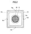
- FIG. 2 is a diagram illustrating a plane defined by a line II-II in FIG. 1 viewed from a direction of an arrow AR1.
- the grommet 10 is a member made of synthetic rubber such as Ethylene Propylene Diene Monomer (EPDM) rubber.
- EPDM Ethylene Propylene Diene Monomer
- the grommet 10 is mainly comprised of a wire harness connecting part 11, an intermediate extending part 12, and a panel connecting part 13.
- the wire harness connecting part 11 is configured to be connected to an outer periphery of the wire harness 20 liquid-tightly.
- the wire harness connecting part 11 has a cylindrical shape, and is bonded to the wire harness 20 liquid-tightly by applying an adhesive such as a modified silicone resin adhesive between an outer surface of the wire harness 20 and an inner surface of the wire harness connecting part 11.
- the wire harness connecting part 11 may be cured in a shape which fits into the wire harness 20 (typically a cylindrical shape) at a state where it remains connected to the wire harness 20.
- the intermediate extending part 12 is a shape-changeable flexible part extending between the wire harness connecting part 11 and the panel connecting part 13.
- the intermediate extending part 12 has an extending-part-shape maintaining part 12a for maintaining its shape in a reflexed state (a rolled-up state) to a direction opposite to an extending direction of the wire harness 20 (opposite to a direction facing the tip where there are the connectors 21).
- the extending-part-shape maintaining part 12a is made of the same material (for example, EPDM rubber) as other parts (the wire harness connecting part 11 and the panel connecting part 13) of the grommet 10.
- the extending-part-shape maintaining part 12a is configured so that it can maintain the rolled-up state of the intermediate extending part 12 as shown in FIG. 1 .
- the extending-part-shape maintaining part 12a is configured to be thicker than other parts or to be coated with a curing agent so that it can maintain its shape, regardless of the state of the intermediate extending part 12 (regardless whether it is rolled up or not).
- the grommet 10 is supplied in a state where the intermediate extending part 12 has been rolled up. This is to allow the worker to begin the connecting procedure of the connectors without the need to roll up the intermediate extending part 12 manually.
- the panel connecting part 13 is configured to be connected to the periphery of the panel opening 31 of the dash panel 30 liquid-tightly.
- the panel connecting part 13 has an opening which fits into a shape of the periphery of the panel opening 31 (for example, a rectangle).
- the periphery of the panel connecting part 13 is reinforced by a plate part 14 so that the periphery can enable fastening by a fastener member such as a bolt.
- the panel connecting part 13 ensures rigidity higher than that of the intermediate extending part 12 by making a joint part 13a, 13b attached to the intermediate extending part 12 thicker than the intermediate extending part 12.
- the panel connecting part 13 helps the intermediate extending part 12 form a curved part 12b which reflexes the intermediate extending part 12, which has been rolled up by the extending-part-shape maintaining part 12a in the direction opposite to the extending direction of the wire harness 20, again in the extending direction of the wire harness 20 in the immediate vicinity of the joint part 13a, 13b.
- the panel connecting part 13 is held in a position away from the dash panel 30 more than a predetermined distance D (for example, 150 mm) at a state where the connectors 21 of the wire harness 20 are connected to the corresponding connectors in the junction box 40.
- a predetermined distance D for example, 150 mm
- the panel connecting part 13 allows the grommet 10 to make room for a work space (a space into which the worker can insert his/her hand, also referred to as "hand space") required for the worker to connect the connectors 21 of the wire harness 20 to the corresponding connectors in the junction box 40.
- the plate part 14 is configured to reinforce the periphery of the panel connecting part 13.
- the plate part 14 is made of metal such as an iron, and fastened, together with the panel connecting part 13, to the dash panel 30 by the fastener member such as a bolt.
- the panel connecting part 13 (the plate part 14) has a rectangle shape which fits into the shape (the rectangle shape) of the periphery of the panel opening 31 as shown in FIG. 2 .
- the panel connecting part 13 (the plate part 14) can seal the panel opening 31 liquid-tightly, it does not necessarily fit into the shape of the panel opening 31, so that it may have an opening having other shapes such as a circular shape, an elliptical shape, a polygonal shape, or the like.
- the wire harness 20 is provided with three connectors 21a, 21b, and 21c at its tip. These connectors pass through the single panel opening 31 and are connected to the corresponding connectors in the junction box 40.
- the wire harness 20 may be provided with one or two connectors at its tip, or may be provided with more than three connectors.
- FIG. 3 is a partial cross-sectional view illustrating a configuration example of the grommet 10 according to the embodiment of the present invention.
- FIG. 3 shows a state after the grommet 10 has been connected to the dash panel 30.
- FIG. 4 is a diagram illustrating a plane defined by a line IV-IV in FIG. 3 viewed from a direction of an arrow AR2.
- the worker After the worker has connected the connectors 21 of the wire harness 20 to the corresponding connectors in the junction box 40 manually, the worker rolls out the intermediate extending part 12, which has been rolled up as shown in FIG. 1 , in a direction toward the dash panel 30. Then, the worker brings the panel connecting part 13 into close contact with an engine-room-side surface 30a (see FIG. 1 ) at the periphery of the panel opening 31 of the dash panel 30. And then, the worker fastens the panel connecting part 13, together with the plate part 14, to the dash panel 30 by using bolts 32a-32d (see FIG. 4 ) inserted into respective bolt holes 15a-15d (see FIG. 2 ) which pierce through the panel connecting part 13 and the plate part 14.
- the extending-part-shape maintaining part 12a maintains its shape (a state where it is reflexed in the opposite direction to the extending direction of the wire harness 20) both in the case where the intermediate extending part 12 has been rolled up in the opposite direction to the direction toward the dash panel 30 and the case where the intermediate extending part 12 has been rolled out in the direction toward the dash board 30.
- the intermediate extending part 12 forms the curved part 12b by reversing its extending direction to the extending direction of the wire harness 20 at a point nearby the extending-part-shape maintaining part 12a which is in a state reflexed to the direction opposite to the extending direction of the wire harness 20, and then extends toward the dash panel 30.
- the worker can return the intermediate extending part 12 to the rolled-up state shown in FIG. 1 by manually rolling up again the intermediate extending part 12 which has been rolled out toward the dash panel 30 as shown in FIG. 3 , by taking advantage of a characteristic of the extending-part-shape maintaining part 12a which maintains its shape regardless of a state of the intermediate extending part 12.
- the grommet 10 can hold the intermediate extending part 12 in the rolled-up state to the direction opposite to the extending direction of the wire harness 20 when the worker connects the connectors 21 of the wire harness 20 to the corresponding connectors in the junction box 40.
- the grommet 10 can make room for a work space for the connecting procedure without a special manual procedure by the worker, and can further improve the workability.
- the grommet 10 can go back and forth repeatedly between a state where the intermediate extending part 12 has been rolled up and a state where the intermediate extending part 12 has been rolled out.
- the worker can make room for a work space by rolling up the intermediate extending part 12 even in the case where the worker starts over the connecting procedure of the connectors 21 of the wire harness 20 again after the worker has rolled out the intermediate extending part 12.
- the intermediate extending part 12 is held in a state where the panel connecting part 13 has been eventually directed toward the dash panel 30 by reversing its extending direction at two points, i.e., at the extending-part-shape maintaining part 12a and at the curved part 12b.
- the intermediate extending part 12 may be, without forming the curved part 12b, held in a state where the panel connecting part 13 has been rolled up and directed to a direction opposite to the direction toward the dash panel 30 (a state where the intermediate extending part 12 and the panel connecting part 13 have been turned inside out completely in comparison to a state where the panel connecting part 13 is connected to the dash panel 30).
- FIGS. 5-8 a grommet 10A according to another embodiment of the present invention will be described. Components common to the grommet 10 shown in FIGS. 1-4 are referred to by the same reference numerals.
- FIG. 5 is a partial cross-sectional view illustrating a configuration example of the grommet 10A according to another embodiment of the present invention, in which a whole extent of the grommet 10A and a part of a wire harness 20 are seen in cross-section (shadow areas).
- FIG. 5 shows a state before the grommet 10A is connected to a dash panel 30.
- Connectors 21 (21a, 21b, and 21c), at a tip of the wire harness 20 to which the grommet 10A is attached, pass through a panel opening 31 of the dash panel 30 from an engine room ER side at a front part of a vehicle.
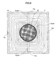
- FIG. 6 is a diagram illustrating a plane defined by a line VI-VI in FIG. 5 viewed from a direction of an arrow AR3.
- the grommet 10A is different from the grommet 10 in FIGS. 1-4 in that it has an intermediate extending part 12A provided with a bellows structure part 12c, and an extending-part-shape maintaining part 12aA for maintaining a state where the bellows structure part 12c is folded.
- other parts of the grommet 10A are in common with the grommet 10. Thus, an explanation relevant to the common points is omitted, and the differences will be explained in detail.
- the intermediate extending part 12A is a shape-changeable flexible part (a part of the grommet 10A) extending between a wire harness connecting part 11 and a panel connecting part 13.
- the intermediate extending part 12A is provided with the bellows structure part 12c which changes its shape from a folded state where the panel connecting part 13 is held in a position away from the dash panel 30 more than a predetermined distance D (for example, 150 mm) when the connectors 21 of the wire harness 20 have been connected to the junction box 40, to a stretched state where the panel connecting part 13 is brought into close contact with the dash panel 30.
- a predetermined distance D for example, 150 mm
- the extending-part-shape maintaining part 12aA is a component of the intermediate extending part 12.
- the extending-part-shape maintaining part 12aA is made of the same material (for example, an EPDM rubber) as other parts of the grommet 10A (the wire harness connecting part 11 and the panel connecting part 13).
- the extending-part-shape maintaining part 12aA includes bellows-structure-part folding tongue-parts 12aA1, 12aA2 and a tongue-part holding tape 12aA3.
- the bellows-structure-part folding tongue-parts 12aA1, 12aA2 are configured to extend from joint parts between the bellows structure part 12c and the panel connecting part 13 in a direction opposite to the extending direction of the wire harness 20.
- the bellows-structure-part folding tongue-parts 12aA1, 12aA2 can maintain the folded state of the bellows structure part 12c by holding respective free ends in contact with an outer surface of the wire harness connecting part 11 while maintaining the folded state of the bellows structure part 12c.
- the tongue-part holding tape 12aA3 is a holding member for holding the respective free ends of the bellows-structure-part folding tongue-parts 12aA1, 12aA2 in contact with the outer surface of the wire harness connecting part 11.
- the tongue-part holding tape 12aA3 is an annular elastic member placed on an outer periphery of the wire harness 20 (the wire harness connecting part 11) stretchably.
- the tongue-part holding tape 12aA3 may be made of material different from those of other parts of the grommet 10A.
- the grommet 10A is supplied in a state where the bellows structure part 12c of the intermediate extending part 12A is folded.
- the extending-part-shape maintaining part 12aA is configured to include the two bellows-structure-part folding tongue-parts 12aA1, 12aA2 placed at respective sides (upper and lower sides) of the wire harness 20 with respect to a central axis of the wire harness 20.
- the extending-part-shape maintaining part 12aA may include a single bellows-structure-part folding tongue-part or more than two bellows-structure-part folding tongue-parts.
- the bellows-structure-part folding tongue-parts 12aA1, 12aA2 are held in contact with the outer periphery of the wire harness 20 (the wire harness connecting part 11) by using the tongue-part holding tape 12aA3.
- the bellows-structure-part folding tongue-parts 12aA1, 12aA2 may be peelably held in contact with the outer periphery of the wire harness 20 (the wire harness connecting part 11) by using an adhesive such as a modified silicone resin adhesive.
- FIG. 7 is a partial cross-sectional view illustrating a configuration example of the grommet 10A.
- FIG. 7 shows a state after the grommet 10A has been connected to the dash panel 30.
- FIG. 8 is a diagram illustrating a plane defined by a line VIII-VIII in FIG. 7 viewed from a direction of an arrow AR4.
- the worker After the worker has manually connected the connectors 21 of the wire harness 20 to the corresponding connectors in the junction box 40, the worker releases the respective free ends of the bellows-structure-part folding tongue-parts 12aA1, 12aA2 by cutting the tongue-part holding tape 12aA3, or by displacing the tongue-part holding tape 12aA3 in the direction opposite to the extending direction of the wire harness 20.
- the worker stretches the bellows structure part 12c of the intermediate extending part 12 which is in the folded state as shown in FIG. 5 so that the bellows structure part 12c spreads toward the dash panel 30.
- the worker brings the panel connecting part 13 into close contact with an engine-room-side surface 30a (see FIG. 5 ) at the periphery of the panel opening 31 of the dash panel 30.
- the worker fastens the panel connecting part 13, together with the plate part 14, to the dash panel 30 by using bolts 32a-32d (see FIG. 8 ) inserted into respective bolt holes 15a-15d (see FIG. 6 ) which pierce through the panel connecting part 13 and the plate part 14.
- the worker can manually fold again the bellows structure part 12c which has been extended in the direction toward the dash panel 30 as shown in FIG. 7 . Then, the worker can hold again the respective free ends of the bellows-structure-part folding tongue-parts 12aA1, 12aA2 in contact with the outer surface of the wire harness connecting part 11 by using the tongue-part holding tape 12aA3 which has been displaced to the direction opposite to the extending direction of the wire harness 20. And thus, the worker can also return the bellows structure part 12c to the folded state as shown in FIG. 5 .
- the grommet 10A holds the bellows structure part 12c of the intermediate extending part 12A at the folded state when the worker connects the connectors 21 of the wire harness 20 to the corresponding connectors in the junction box 40.
- the grommet 10A can make room for a work space for the connecting procedure without a special manual procedure by the worker, and can further improve the workability.
- the grommet 10A can go back and forth repeatedly between a state where the bellows structure part 12c has been folded and a state where the bellows structure part 12c has been stretched in case where the worker releases the bellows-structure-part folding tongue-parts 12aA1, 12aA2 from the outer surface of the wire harness connecting part 11 by displacing the tongue-part holding tape 12aA3.
- the worker can make room for a work space by folding the bellows structure part 12c even in the case where the worker starts over the connecting procedure of the connectors 21 of the wire harness 20 again after the worker has stretched the bellows structure part 12c.
- the grommet 10A can be stretched so that the bellows structure part 12c in the folded state spreads toward the dash panel 30.
- a size of an opening of the panel connecting part 13 can be set flexibly.
- the grommet 10A can fit into panel openings with a variety of sizes including a panel opening with relatively large size which allows plural connectors to pass through.
- the bellows structure part 12c may be configured to be stretched cylindrically along the wire harness 20 without spreading.
- a flat plate part having a size about equal to the size of the opening of the panel connecting part 13 may be placed at the joint part between the wire harness connecting part 11 and the intermediate extending part 12A (the bellows structure part 12c).
- the bellows structure part 12c is held so that its folded part is piled up in a direction perpendicular to the outer surface of the wire harness 20.
- the bellows structure part 12c may be held so that its folded part is piled up in a direction parallel to the outer surface of the wire harness 20.
- the bellows structure part 12c may be held so that its folded part is piled up in the direction opposite to the extending direction of the wire harness 20 beyond the direction perpendicular to the outer surface of the wire harness 20.
- the grommet 10A holds the bellows structure part 12c in the folded state by using the bellows-structure-part folding tongue-part 12aA1, 12aA2 and the tongue-part holding tape 12aA3.
- the grommet 10A may omit the bellows-structure-part folding tongue-part 12aA1, 12aA2 and the tongue-part holding tape 12aA3.
- the grommet 10A may hold the flexible intermediate extending part 12A without the bellows structure in a state rolled up toward the direction opposite to the extending direction of the wire harness 20, by peelably bonding a part thereof (for example, a joint part between the intermediate extending part 12A and the panel connecting part 13) to the outer surface of the wire harness connecting part 11 by using an adhesive.
- the grommet 10A may omit the bellows-structure-part folding tongue-part 12aA1, 12aA2 and the tongue-part holding tape 12aA3.
- the grommet 10A may be configured to partially change thickness or flexibility of the intermediate extending part 12A.
- the grommet 10A can generate a certain shape-maintaining force which enables the folded state of the bellows structure part 12c to be maintained, and may allow the worker to exert a force on the bellows structure part 12c and to bring the panel connecting part 13 into close contact with the dash panel 30.
- the grommet 10A may allow the bellows structure part 12c to return to the folded state, and may allow the panel connecting part 13 to automatically get away from the dash panel 30 to a predetermined position.
- the intermediate extending part 12A does not have to employ the bellows structure part 12c.
- the intermediate extending part 12A may employ a structure which extends smoothly.
- the grommets 10, 10A are attached to the wire harness 20 having a circular cross-section.
- the grommets 10, 10A may be attached to a wire harness having other cross-sectional shapes such as an elliptical shape, a rectangle shape, or the like.
Landscapes
- Engineering & Computer Science (AREA)
- Architecture (AREA)
- Civil Engineering (AREA)
- Structural Engineering (AREA)
- Mechanical Engineering (AREA)
- Manufacturing & Machinery (AREA)
- Microelectronics & Electronic Packaging (AREA)
- Installation Of Indoor Wiring (AREA)
- Insulating Bodies (AREA)
Abstract
Description
- The present invention relates to a grommet attached to a wire harness and a method of mounting the grommet to a panel opening. In particular, the present invention relates to a grommet which is able to make room for a work space for attaching a connector at a tip of the wire harness to a corresponding connector in a junction box placed in the panel opening and a method of mounting the grommet to the panel opening.
- Conventionally, a waterproof grommet attached to a wire harness for improving the connecting workability of a connector at a panel opening is known (see Patent Document 1 for example).
- This waterproof grommet is configured to be fixed to a panel by using two bolts. When the connector is connected to the corresponding connector, the waterproof grommet is rotated 90 degrees with respect to a normal fixed position about a bolt axis as a rotational axis. Thus, a waterproof grommet body is displaced from the panel opening. As a result, the waterproof grommet can make room for a space for a connecting procedure of the connectors.
- Also, a side wall of this waterproof grommet is comprised of a stretchable bellows part. The waterproof grommet can completely expose the connectors within the bellows when the bellows are compressed. As a result, the waterproof grommet can rotate about the bolt axis as the rotational axis while avoiding interference with the connectors.
-
- [Patent Document 1] Japanese Patent Publication No.
2001-309528 - However, in a case of mounting the waterproof grommet in Patent Document 1 to the panel opening, a worker has to compress the bellows part of the waterproof grommet to avoid interference between the side wall of the waterproof grommet and the connectors when the worker rotates the waterproof grommet about the bolt axis as the rotational axis to make room for a space for the connecting procedure of the connectors, or when the worker returns the rotated waterproof grommet to the normal fixed position after the connection procedure of the connectors has been completed. Thus, it cannot be said that the connecting workability has sufficiently improved.
- Also, even if the worker makes room for the work space by rotating the waterproof grommet by 90 degrees, the worker cannot completely avoid the interference between a flange part of the waterproof grommet and the connectors. Thus, also in this regard, it cannot be said that the connecting workability has sufficiently improved.
- In consideration of the above point, the present invention is intended to provide a grommet which further improves the connecting workability of a connector and a method of mounting the grommet to a panel opening.
- To achieve the above objective, a grommet according to an embodiment of the present invention includes a wire harness connecting part configured to be liquid-tightly connected to a wire harness, a panel connecting part configured to be able to be liquid-tightly connected to a panel opening, an extending part configured to shape-changeably extend between the wire harness connecting part and the panel connecting part, and an extending-part-shape maintaining part configured to maintain a shape of the extending part in a state where a distance between the wire harness connecting part and the panel connecting part in a length direction of the wire harness is shorter than that of the case where the panel connecting part is liquid-tightly connected to the panel opening.
- Also, a method of mounting a grommet to a panel opening according to an embodiment of the present invention, the grommet comprising a wire harness connecting part configured to be liquid-tightly connected to a wire harness, a panel connecting part configured to be able to be liquid-tightly connected to a panel opening, an extending part configured to shape-changeably extend between the wire harness connecting part and the panel connecting part, and an extending-part-shape maintaining part configured to maintain a shape of the extending part, includes steps of connecting a connector at a tip of the wire harness and a corresponding connector disposed in the panel opening while maintaining by the extending-part-shape maintaining part the shape of the extending part in a state where a distance between the wire harness connecting part and the panel connecting part in a length direction of the wire harness is shorter than that of the case where the panel connecting part is liquid-tightly connected to the panel opening, and coupling the panel connecting part to the panel opening by lengthening the distance through changing the shape of the extending part.
- According to the above means, the present invention can provide a grommet which further improves the connecting workability of a connector and a method of mounting the grommet to a panel opening.
-
-
FIG. 1 is a partial cross-sectional view illustrating a configuration example of a grommet according to an embodiment of the present invention (before it is connected to a panel). -
FIG. 2 is a diagram illustrating a plane defined by a line II-II inFIG. 1 viewed from a direction of an arrow AR1. -
FIG. 3 is a partial cross-sectional view illustrating a state of the grommet inFIG. 1 after it is connected to the panel. -
FIG. 4 is a diagram illustrating a plane defined by a line IV-IV inFIG. 3 viewed from a direction of an arrow AR2. -
FIG. 5 is a partial cross-sectional view illustrating a configuration example of a grommet according to another embodiment of the present invention (before it is connected to a panel). -
FIG. 6 is a diagram illustrating a plane defined by a line VI-VI inFIG. 5 viewed from a direction of an arrow AR3. -
FIG. 7 is a partial cross-sectional view illustrating a state of the grommet inFIG. 5 after it is connected to the panel. -
FIG. 8 is a diagram illustrating a plane defined by a line VIII-VIII inFIG. 7 viewed from a direction of an arrow AR4. - With reference to figures, a mode for carrying out the present invention will be explained below.
-
FIG. 1 is a partial cross-sectional view illustrating a configuration example of agrommet 10 according to an embodiment of the present invention, in which a whole extent of thegrommet 10 and a part of awire harness 20 are seen in cross-section (shadow areas).FIG. 1 shows a state before thegrommet 10 attached to thewire harness 20 is connected to adash panel 30. Connectors 21 (21a, 21b, and 21c), at a tip of thewire harness 20 to which thegrommet 10 is attached, pass through a panel opening 31 of thedash panel 30 from an engine room ER side at a front part of a vehicle. Also, theconnectors 21 have been connected to corresponding connectors in ajunction box 40 of an instrument panel installed in a vehicle interior VI (a space where an air conditioning unit and the like are installed).FIG. 2 is a diagram illustrating a plane defined by a line II-II inFIG. 1 viewed from a direction of an arrow AR1. - The
grommet 10 is a member made of synthetic rubber such as Ethylene Propylene Diene Monomer (EPDM) rubber. Thegrommet 10 is mainly comprised of a wireharness connecting part 11, anintermediate extending part 12, and apanel connecting part 13. - The wire
harness connecting part 11 is configured to be connected to an outer periphery of thewire harness 20 liquid-tightly. For example, the wireharness connecting part 11 has a cylindrical shape, and is bonded to thewire harness 20 liquid-tightly by applying an adhesive such as a modified silicone resin adhesive between an outer surface of thewire harness 20 and an inner surface of the wireharness connecting part 11. - The wire
harness connecting part 11 may be cured in a shape which fits into the wire harness 20 (typically a cylindrical shape) at a state where it remains connected to thewire harness 20. - The intermediate extending
part 12 is a shape-changeable flexible part extending between the wireharness connecting part 11 and thepanel connecting part 13. For example, theintermediate extending part 12 has an extending-part-shape maintaining part 12a for maintaining its shape in a reflexed state (a rolled-up state) to a direction opposite to an extending direction of the wire harness 20 (opposite to a direction facing the tip where there are the connectors 21). - The extending-part-
shape maintaining part 12a is made of the same material (for example, EPDM rubber) as other parts (the wireharness connecting part 11 and the panel connecting part 13) of thegrommet 10. The extending-part-shape maintaining part 12a is configured so that it can maintain the rolled-up state of theintermediate extending part 12 as shown inFIG. 1 . For example, the extending-part-shape maintaining part 12a is configured to be thicker than other parts or to be coated with a curing agent so that it can maintain its shape, regardless of the state of the intermediate extending part 12 (regardless whether it is rolled up or not). - Preferably, the
grommet 10 is supplied in a state where theintermediate extending part 12 has been rolled up. This is to allow the worker to begin the connecting procedure of the connectors without the need to roll up theintermediate extending part 12 manually. - The
panel connecting part 13 is configured to be connected to the periphery of the panel opening 31 of thedash panel 30 liquid-tightly. For example, thepanel connecting part 13 has an opening which fits into a shape of the periphery of the panel opening 31 (for example, a rectangle). Also, the periphery of thepanel connecting part 13 is reinforced by aplate part 14 so that the periphery can enable fastening by a fastener member such as a bolt. - The
panel connecting part 13 ensures rigidity higher than that of theintermediate extending part 12 by making ajoint part intermediate extending part 12 thicker than the intermediate extendingpart 12. In case where theintermediate extending part 12 is rolled up as shown inFIG. 1 , thepanel connecting part 13 helps theintermediate extending part 12 form acurved part 12b which reflexes theintermediate extending part 12, which has been rolled up by the extending-part-shape maintaining part 12a in the direction opposite to the extending direction of thewire harness 20, again in the extending direction of thewire harness 20 in the immediate vicinity of thejoint part - As a result, in case where the
intermediate extending part 12 is rolled up as shown inFIG. 1 , thepanel connecting part 13 is held in a position away from thedash panel 30 more than a predetermined distance D (for example, 150 mm) at a state where theconnectors 21 of thewire harness 20 are connected to the corresponding connectors in thejunction box 40. Thus, thepanel connecting part 13 allows thegrommet 10 to make room for a work space (a space into which the worker can insert his/her hand, also referred to as "hand space") required for the worker to connect theconnectors 21 of thewire harness 20 to the corresponding connectors in thejunction box 40. - The
plate part 14 is configured to reinforce the periphery of thepanel connecting part 13. For example, theplate part 14 is made of metal such as an iron, and fastened, together with thepanel connecting part 13, to thedash panel 30 by the fastener member such as a bolt. - In the present embodiment, the panel connecting part 13 (the plate part 14) has a rectangle shape which fits into the shape (the rectangle shape) of the periphery of the panel opening 31 as shown in
FIG. 2 . However, if the panel connecting part 13 (the plate part 14) can seal the panel opening 31 liquid-tightly, it does not necessarily fit into the shape of the panel opening 31, so that it may have an opening having other shapes such as a circular shape, an elliptical shape, a polygonal shape, or the like. - Also, in the present embodiment, the
wire harness 20 is provided with threeconnectors single panel opening 31 and are connected to the corresponding connectors in thejunction box 40. However, thewire harness 20 may be provided with one or two connectors at its tip, or may be provided with more than three connectors. - Along with
FIG. 1 ,FIG. 3 is a partial cross-sectional view illustrating a configuration example of thegrommet 10 according to the embodiment of the present invention.FIG. 3 shows a state after thegrommet 10 has been connected to thedash panel 30. Also,FIG. 4 is a diagram illustrating a plane defined by a line IV-IV inFIG. 3 viewed from a direction of an arrow AR2. - After the worker has connected the
connectors 21 of thewire harness 20 to the corresponding connectors in thejunction box 40 manually, the worker rolls out the intermediate extendingpart 12, which has been rolled up as shown inFIG. 1 , in a direction toward thedash panel 30. Then, the worker brings thepanel connecting part 13 into close contact with an engine-room-side surface 30a (seeFIG. 1 ) at the periphery of the panel opening 31 of thedash panel 30. And then, the worker fastens thepanel connecting part 13, together with theplate part 14, to thedash panel 30 by usingbolts 32a-32d (seeFIG. 4 ) inserted intorespective bolt holes 15a-15d (seeFIG. 2 ) which pierce through thepanel connecting part 13 and theplate part 14. - As shown in
FIGS. 1 and3 , the extending-part-shape maintaining part 12a maintains its shape (a state where it is reflexed in the opposite direction to the extending direction of the wire harness 20) both in the case where the intermediate extendingpart 12 has been rolled up in the opposite direction to the direction toward thedash panel 30 and the case where the intermediate extendingpart 12 has been rolled out in the direction toward thedash board 30. - Thus, if the intermediate extending
part 12 has been rolled out in the direction toward thedash panel 30 as shown inFIG. 3 , it forms thecurved part 12b by reversing its extending direction to the extending direction of thewire harness 20 at a point nearby the extending-part-shape maintaining part 12a which is in a state reflexed to the direction opposite to the extending direction of thewire harness 20, and then extends toward thedash panel 30. - Also, the worker can return the intermediate extending
part 12 to the rolled-up state shown inFIG. 1 by manually rolling up again the intermediate extendingpart 12 which has been rolled out toward thedash panel 30 as shown inFIG. 3 , by taking advantage of a characteristic of the extending-part-shape maintaining part 12a which maintains its shape regardless of a state of the intermediate extendingpart 12. - Due to the above configuration, the
grommet 10 can hold the intermediate extendingpart 12 in the rolled-up state to the direction opposite to the extending direction of thewire harness 20 when the worker connects theconnectors 21 of thewire harness 20 to the corresponding connectors in thejunction box 40. Thus, thegrommet 10 can make room for a work space for the connecting procedure without a special manual procedure by the worker, and can further improve the workability. - Also, the
grommet 10 can go back and forth repeatedly between a state where the intermediate extendingpart 12 has been rolled up and a state where the intermediate extendingpart 12 has been rolled out. Thus, the worker can make room for a work space by rolling up the intermediate extendingpart 12 even in the case where the worker starts over the connecting procedure of theconnectors 21 of thewire harness 20 again after the worker has rolled out the intermediate extendingpart 12. - Also, the intermediate extending
part 12 is held in a state where thepanel connecting part 13 has been eventually directed toward thedash panel 30 by reversing its extending direction at two points, i.e., at the extending-part-shape maintaining part 12a and at thecurved part 12b. However, the intermediate extendingpart 12 may be, without forming thecurved part 12b, held in a state where thepanel connecting part 13 has been rolled up and directed to a direction opposite to the direction toward the dash panel 30 (a state where the intermediate extendingpart 12 and thepanel connecting part 13 have been turned inside out completely in comparison to a state where thepanel connecting part 13 is connected to the dash panel 30). - Next, referring to
FIGS. 5-8 , agrommet 10A according to another embodiment of the present invention will be described. Components common to thegrommet 10 shown inFIGS. 1-4 are referred to by the same reference numerals. -
FIG. 5 is a partial cross-sectional view illustrating a configuration example of thegrommet 10A according to another embodiment of the present invention, in which a whole extent of thegrommet 10A and a part of awire harness 20 are seen in cross-section (shadow areas).FIG. 5 shows a state before thegrommet 10A is connected to adash panel 30. Connectors 21 (21a, 21b, and 21c), at a tip of thewire harness 20 to which thegrommet 10A is attached, pass through a panel opening 31 of thedash panel 30 from an engine room ER side at a front part of a vehicle. Also, theconnectors 21 have been connected to corresponding connectors in ajunction box 40 of an instrument panel installed in a vehicle interior VI (a space where an air conditioning unit and the like are installed).FIG. 6 is a diagram illustrating a plane defined by a line VI-VI inFIG. 5 viewed from a direction of an arrow AR3. - The
grommet 10A is different from thegrommet 10 inFIGS. 1-4 in that it has an intermediate extendingpart 12A provided with abellows structure part 12c, and an extending-part-shape maintaining part 12aA for maintaining a state where thebellows structure part 12c is folded. However, other parts of thegrommet 10A are in common with thegrommet 10. Thus, an explanation relevant to the common points is omitted, and the differences will be explained in detail. - The intermediate extending
part 12A is a shape-changeable flexible part (a part of thegrommet 10A) extending between a wireharness connecting part 11 and apanel connecting part 13. The intermediate extendingpart 12A is provided with thebellows structure part 12c which changes its shape from a folded state where thepanel connecting part 13 is held in a position away from thedash panel 30 more than a predetermined distance D (for example, 150 mm) when theconnectors 21 of thewire harness 20 have been connected to thejunction box 40, to a stretched state where thepanel connecting part 13 is brought into close contact with thedash panel 30. - The extending-part-shape maintaining part 12aA is a component of the intermediate extending
part 12. The extending-part-shape maintaining part 12aA is made of the same material (for example, an EPDM rubber) as other parts of thegrommet 10A (the wireharness connecting part 11 and the panel connecting part 13). The extending-part-shape maintaining part 12aA includes bellows-structure-part folding tongue-parts 12aA1, 12aA2 and a tongue-part holding tape 12aA3. - The bellows-structure-part folding tongue-parts 12aA1, 12aA2 are configured to extend from joint parts between the
bellows structure part 12c and thepanel connecting part 13 in a direction opposite to the extending direction of thewire harness 20. The bellows-structure-part folding tongue-parts 12aA1, 12aA2 can maintain the folded state of thebellows structure part 12c by holding respective free ends in contact with an outer surface of the wireharness connecting part 11 while maintaining the folded state of thebellows structure part 12c. - The tongue-part holding tape 12aA3 is a holding member for holding the respective free ends of the bellows-structure-part folding tongue-parts 12aA1, 12aA2 in contact with the outer surface of the wire
harness connecting part 11. For example, the tongue-part holding tape 12aA3 is an annular elastic member placed on an outer periphery of the wire harness 20 (the wire harness connecting part 11) stretchably. The tongue-part holding tape 12aA3 may be made of material different from those of other parts of thegrommet 10A. - Preferably, the
grommet 10A is supplied in a state where thebellows structure part 12c of the intermediate extendingpart 12A is folded. - In the present embodiment, as shown in
FIG. 6 , the extending-part-shape maintaining part 12aA is configured to include the two bellows-structure-part folding tongue-parts 12aA1, 12aA2 placed at respective sides (upper and lower sides) of thewire harness 20 with respect to a central axis of thewire harness 20. However, the extending-part-shape maintaining part 12aA may include a single bellows-structure-part folding tongue-part or more than two bellows-structure-part folding tongue-parts. - Also, in the present embodiment, the bellows-structure-part folding tongue-parts 12aA1, 12aA2 are held in contact with the outer periphery of the wire harness 20 (the wire harness connecting part 11) by using the tongue-part holding tape 12aA3. However, the bellows-structure-part folding tongue-parts 12aA1, 12aA2 may be peelably held in contact with the outer periphery of the wire harness 20 (the wire harness connecting part 11) by using an adhesive such as a modified silicone resin adhesive.
- Along with
FIG. 5 ,FIG. 7 is a partial cross-sectional view illustrating a configuration example of thegrommet 10A.FIG. 7 shows a state after thegrommet 10A has been connected to thedash panel 30. Also,FIG. 8 is a diagram illustrating a plane defined by a line VIII-VIII inFIG. 7 viewed from a direction of an arrow AR4. - After the worker has manually connected the
connectors 21 of thewire harness 20 to the corresponding connectors in thejunction box 40, the worker releases the respective free ends of the bellows-structure-part folding tongue-parts 12aA1, 12aA2 by cutting the tongue-part holding tape 12aA3, or by displacing the tongue-part holding tape 12aA3 in the direction opposite to the extending direction of thewire harness 20. - Subsequently, the worker stretches the
bellows structure part 12c of the intermediate extendingpart 12 which is in the folded state as shown inFIG. 5 so that thebellows structure part 12c spreads toward thedash panel 30. Then, as shown inFIG. 7 , the worker brings thepanel connecting part 13 into close contact with an engine-room-side surface 30a (seeFIG. 5 ) at the periphery of the panel opening 31 of thedash panel 30. And then, the worker fastens thepanel connecting part 13, together with theplate part 14, to thedash panel 30 by usingbolts 32a-32d (seeFIG. 8 ) inserted intorespective bolt holes 15a-15d (seeFIG. 6 ) which pierce through thepanel connecting part 13 and theplate part 14. - Also, the worker can manually fold again the
bellows structure part 12c which has been extended in the direction toward thedash panel 30 as shown inFIG. 7 . Then, the worker can hold again the respective free ends of the bellows-structure-part folding tongue-parts 12aA1, 12aA2 in contact with the outer surface of the wireharness connecting part 11 by using the tongue-part holding tape 12aA3 which has been displaced to the direction opposite to the extending direction of thewire harness 20. And thus, the worker can also return thebellows structure part 12c to the folded state as shown inFIG. 5 . - Due to the above configuration, the
grommet 10A holds thebellows structure part 12c of the intermediate extendingpart 12A at the folded state when the worker connects theconnectors 21 of thewire harness 20 to the corresponding connectors in thejunction box 40. Thus, thegrommet 10A can make room for a work space for the connecting procedure without a special manual procedure by the worker, and can further improve the workability. - Also, the
grommet 10A can go back and forth repeatedly between a state where thebellows structure part 12c has been folded and a state where thebellows structure part 12c has been stretched in case where the worker releases the bellows-structure-part folding tongue-parts 12aA1, 12aA2 from the outer surface of the wireharness connecting part 11 by displacing the tongue-part holding tape 12aA3. Thus, the worker can make room for a work space by folding thebellows structure part 12c even in the case where the worker starts over the connecting procedure of theconnectors 21 of thewire harness 20 again after the worker has stretched thebellows structure part 12c. - Also, the
grommet 10A can be stretched so that thebellows structure part 12c in the folded state spreads toward thedash panel 30. Thus, a size of an opening of thepanel connecting part 13 can be set flexibly. And thus, thegrommet 10A can fit into panel openings with a variety of sizes including a panel opening with relatively large size which allows plural connectors to pass through. - Also, the
bellows structure part 12c may be configured to be stretched cylindrically along thewire harness 20 without spreading. In that case, a flat plate part having a size about equal to the size of the opening of thepanel connecting part 13 may be placed at the joint part between the wireharness connecting part 11 and the intermediate extendingpart 12A (thebellows structure part 12c). - Also, as shown in
FIG.5 , thebellows structure part 12c is held so that its folded part is piled up in a direction perpendicular to the outer surface of thewire harness 20. However, thebellows structure part 12c may be held so that its folded part is piled up in a direction parallel to the outer surface of thewire harness 20. - Also, the
bellows structure part 12c may be held so that its folded part is piled up in the direction opposite to the extending direction of thewire harness 20 beyond the direction perpendicular to the outer surface of thewire harness 20. - The preferable embodiments of the present invention have been explained in detail. However, the present invention shall not be restricted to the above embodiments. Various changes and substitutions may be made to the above embodiments without departing from the scope of the present invention.
- For example, in the above embodiment, the
grommet 10A holds thebellows structure part 12c in the folded state by using the bellows-structure-part folding tongue-part 12aA1, 12aA2 and the tongue-part holding tape 12aA3. However, thegrommet 10A may omit the bellows-structure-part folding tongue-part 12aA1, 12aA2 and the tongue-part holding tape 12aA3. In that case, thegrommet 10A may hold the flexible intermediate extendingpart 12A without the bellows structure in a state rolled up toward the direction opposite to the extending direction of thewire harness 20, by peelably bonding a part thereof (for example, a joint part between the intermediate extendingpart 12A and the panel connecting part 13) to the outer surface of the wireharness connecting part 11 by using an adhesive. - Also, in the above embodiment, the
grommet 10A may omit the bellows-structure-part folding tongue-part 12aA1, 12aA2 and the tongue-part holding tape 12aA3. On that basis, thegrommet 10A may be configured to partially change thickness or flexibility of the intermediate extendingpart 12A. Thus, thegrommet 10A can generate a certain shape-maintaining force which enables the folded state of thebellows structure part 12c to be maintained, and may allow the worker to exert a force on thebellows structure part 12c and to bring thepanel connecting part 13 into close contact with thedash panel 30. And thus, when the worker gets his/her hands off of thebellows structure part 12c, thegrommet 10A may allow thebellows structure part 12c to return to the folded state, and may allow thepanel connecting part 13 to automatically get away from thedash panel 30 to a predetermined position. In this case, the intermediate extendingpart 12A does not have to employ thebellows structure part 12c. The intermediate extendingpart 12A may employ a structure which extends smoothly. - Also, in the above embodiments, the
grommets wire harness 20 having a circular cross-section. However, thegrommets -
- 10, 10A
- grommet
- 11
- wire harness
- 12, 12A
- intermediate extending part
- 12a, 12aA
- extending-part-shape maintaining part
- 12aA1, 12aA2
- bellows-structure-part folding tongue-part
- 12aA3
- tongue-part holding tape
- 12b
- curved part
- 12c
- bellows structure part
- 13
- panel connecting part
- 14
- plate part
- 15a-15d
- bolt hole
- 20
- wire harness
- 21, 21a-21c
- connector
- 30
- dash panel
- 30a
- dash panel surface
- 31
- panel opening
- 32a-32d
- bolt
- ER
- engine room
- VI
- vehicle interior
Claims (5)
- A grommet, comprising:a wire harness connecting part configured to be liquid-tightly connected to a wire harness,a panel connecting part configured to be able to be liquid-tightly connected to a panel opening,an extending part configured to shape-changeably extend between the wire harness connecting part and the panel connecting part,an extending-part-shape maintaining part configured to maintain a shape of the extending part in a state where a distance between the wire harness connecting part and the panel connecting part in a length direction of the wire harness is shorter than that of the case where the panel connecting part is liquid-tightly connected to the panel opening.
- A grommet according to claim 1, wherein the extending-part-shape maintaining part comprises a shape-maintaining structure configured to maintain the shape of the extending part in a state where the extending part is rolled up.
- A grommet according to claim 2, wherein the shape-maintaining structure can switch between a state where the extending part has been rolled up toward the wire harness connecting part and a state where the extending part has been rolled out toward the panel connecting part.
- A grommet according to claim 1, wherein the extending part comprises a bellows structure, and the extending-part-shape maintaining part maintains the shape of the extending part in a state where the bellows structure of the extending part is folded up.
- A method of mounting a grommet to a panel opening, the grommet comprising a wire harness connecting part configured to be liquid-tightly connected to a wire harness, a panel connecting part configured to be able to be liquid-tightly connected to a panel opening, an extending part configured to shape-changeably extend between the wire harness connecting part and the panel connecting part, and an extending-part-shape maintaining part configured to maintain a shape of the extending part, the method comprising steps of:connecting a connector at a tip of the wire harness and a corresponding connector disposed in the panel opening while maintaining by the extending-part-shape maintaining part the shape of the extending part in a state where a distance between the wire harness connecting part and the panel connecting part in a length direction of the wire harness is shorter than that of the case where the panel connecting part is liquid-tightly connected to the panel opening, andcoupling the panel connecting part to the panel opening by lengthening the distance through changing the shape of the extending part.
Applications Claiming Priority (1)
| Application Number | Priority Date | Filing Date | Title |
|---|---|---|---|
| PCT/JP2011/050524 WO2012095986A1 (en) | 2011-01-14 | 2011-01-14 | Grommet and method of installing thereof |
Publications (3)
| Publication Number | Publication Date |
|---|---|
| EP2665145A1 true EP2665145A1 (en) | 2013-11-20 |
| EP2665145A4 EP2665145A4 (en) | 2013-11-20 |
| EP2665145B1 EP2665145B1 (en) | 2016-12-21 |
Family
ID=46506907
Family Applications (1)
| Application Number | Title | Priority Date | Filing Date |
|---|---|---|---|
| EP11855701.6A Not-in-force EP2665145B1 (en) | 2011-01-14 | 2011-01-14 | Grommet and method of installing thereof |
Country Status (5)
| Country | Link |
|---|---|
| US (1) | US8835778B2 (en) |
| EP (1) | EP2665145B1 (en) |
| JP (1) | JP5553113B2 (en) |
| CN (1) | CN103299497B (en) |
| WO (1) | WO2012095986A1 (en) |
Families Citing this family (4)
| Publication number | Priority date | Publication date | Assignee | Title |
|---|---|---|---|---|
| CN108347004A (en) * | 2018-04-17 | 2018-07-31 | 广东电网有限责任公司 | A kind of exposed conductor of primary cable quickly encapsulates insulation sleeve |
| JP7268576B2 (en) * | 2019-10-30 | 2023-05-08 | 住友電装株式会社 | Grommet |
| JP7616034B2 (en) * | 2021-11-26 | 2025-01-17 | 株式会社豊田自動織機 | Electric Compressor |
| DE102023211773B3 (en) | 2023-11-27 | 2025-01-30 | Volkswagen Aktiengesellschaft | Grommet for holding cables, method for mounting a grommet and motor vehicle |
Family Cites Families (20)
| Publication number | Priority date | Publication date | Assignee | Title |
|---|---|---|---|---|
| JPH0616192Y2 (en) * | 1988-12-27 | 1994-04-27 | トヨタ自動車株式会社 | Grommet for wire harness |
| JP2947000B2 (en) * | 1993-06-08 | 1999-09-13 | 住友電装株式会社 | Wire harness waterproofing method and waterproofing structure |
| JPH09284953A (en) | 1996-04-08 | 1997-10-31 | Yazaki Corp | Grommet with long tubular part |
| JP2000358315A (en) | 1999-06-11 | 2000-12-26 | Calsonic Kansei Corp | Grommet |
| JP3599233B2 (en) | 1999-12-24 | 2004-12-08 | 矢崎総業株式会社 | Module connector mounting structure |
| JP3627974B2 (en) | 2000-04-21 | 2005-03-09 | 矢崎総業株式会社 | Waterproof structure and assembly method for panel feed-through connector |
| JP3757106B2 (en) * | 2000-10-27 | 2006-03-22 | 矢崎総業株式会社 | Grommet |
| JP3825278B2 (en) * | 2001-05-29 | 2006-09-27 | 矢崎総業株式会社 | Grommet |
| JP2003011249A (en) * | 2001-07-03 | 2003-01-15 | Dainippon Printing Co Ltd | Paper cup forming machine |
| JP2003111249A (en) | 2001-09-28 | 2003-04-11 | Fujikura Ltd | Grommet |
| US6927338B2 (en) * | 2002-10-09 | 2005-08-09 | The Xlo Group Of Companies, Inc. | Wire pass through seal with grommets |
| JP3915673B2 (en) * | 2002-11-20 | 2007-05-16 | 住友電装株式会社 | Grommet and protector mounting structure |
| US6897380B2 (en) * | 2002-11-29 | 2005-05-24 | Sumitomo Wiring Systems, Ltd. | Grommet for a wire harness |
| JP4405276B2 (en) | 2004-02-16 | 2010-01-27 | 矢崎総業株式会社 | Waterproof structure and wiring method for vehicle door harness |
| FR2904398B1 (en) | 2006-07-25 | 2008-09-26 | Societe Des Polymeres Barre-Thomas | FLEXIBLE PIPE COUPLING DEVICE, IN PARTICULAR FOR A VEHICLE PASSENGER DOOR OR VEHICLE CABLES |
| JP4791396B2 (en) | 2007-03-19 | 2011-10-12 | 矢崎総業株式会社 | Grommet and assembly method |
| JP2009201179A (en) * | 2008-02-19 | 2009-09-03 | Yazaki Corp | Grommet |
| JP5157513B2 (en) * | 2008-02-20 | 2013-03-06 | 住友電装株式会社 | Grommet |
| JP2012239353A (en) * | 2011-05-13 | 2012-12-06 | Sumitomo Wiring Syst Ltd | Grommet |
| JP5747694B2 (en) * | 2011-07-06 | 2015-07-15 | 住友電装株式会社 | Grommet |
-
2011
- 2011-01-14 JP JP2012552606A patent/JP5553113B2/en not_active Expired - Fee Related
- 2011-01-14 WO PCT/JP2011/050524 patent/WO2012095986A1/en not_active Ceased
- 2011-01-14 US US13/978,555 patent/US8835778B2/en not_active Expired - Fee Related
- 2011-01-14 EP EP11855701.6A patent/EP2665145B1/en not_active Not-in-force
- 2011-01-14 CN CN201180064319.5A patent/CN103299497B/en not_active Expired - Fee Related
Also Published As
| Publication number | Publication date |
|---|---|
| US8835778B2 (en) | 2014-09-16 |
| EP2665145B1 (en) | 2016-12-21 |
| WO2012095986A1 (en) | 2012-07-19 |
| CN103299497B (en) | 2016-08-10 |
| CN103299497A (en) | 2013-09-11 |
| JPWO2012095986A1 (en) | 2014-06-09 |
| US20130292158A1 (en) | 2013-11-07 |
| JP5553113B2 (en) | 2014-07-16 |
| EP2665145A4 (en) | 2013-11-20 |
Similar Documents
| Publication | Publication Date | Title |
|---|---|---|
| JP5772444B2 (en) | Clamp | |
| EP2665145B1 (en) | Grommet and method of installing thereof | |
| US9672955B2 (en) | Clamp and wire harness having clamp | |
| EP2096001A1 (en) | Exterior protective material for door wire harness and wire arrangement structure for the door wire harness | |
| CN106165228B (en) | Grommet and harness | |
| WO2009104286A1 (en) | Grommet | |
| JP2018046704A (en) | Grommet mounting structure | |
| JP6465001B2 (en) | Clamp for wire harness | |
| US8895860B2 (en) | Grommet | |
| JP2008284966A (en) | Service hole cover mounting method and service hole cover therefor | |
| JP2016059110A (en) | Clamp for wiring harness | |
| EP3819172B1 (en) | Wire harness | |
| WO2006106595A1 (en) | Hinge mechanism of display for vehicle | |
| JP2004026060A (en) | Flexible material mounting structure | |
| JP5313631B2 (en) | Interior member mounting structure | |
| JP5215201B2 (en) | Grommet | |
| CN116941153A (en) | Wire covers and wiring harnesses | |
| JP5924252B2 (en) | Grommet | |
| US20240153676A1 (en) | Grommet unit and wire harness | |
| JP3309805B2 (en) | Grommet | |
| JP2020069957A (en) | Wire harness fixture | |
| JP2008207741A (en) | Wiring structure of door harness | |
| JP2025180347A (en) | Drip-proof construction of electronic devices | |
| JP2001239898A (en) | Harness fixing structure | |
| JPH08142777A (en) | Harness fixing structure |
Legal Events
| Date | Code | Title | Description |
|---|---|---|---|
| PUAI | Public reference made under article 153(3) epc to a published international application that has entered the european phase |
Free format text: ORIGINAL CODE: 0009012 |
|
| 17P | Request for examination filed |
Effective date: 20130701 |
|
| A4 | Supplementary search report drawn up and despatched |
Effective date: 20131007 |
|
| AK | Designated contracting states |
Kind code of ref document: A1 Designated state(s): AL AT BE BG CH CY CZ DE DK EE ES FI FR GB GR HR HU IE IS IT LI LT LU LV MC MK MT NL NO PL PT RO RS SE SI SK SM TR |
|
| DAX | Request for extension of the european patent (deleted) | ||
| 17Q | First examination report despatched |
Effective date: 20140716 |
|
| GRAP | Despatch of communication of intention to grant a patent |
Free format text: ORIGINAL CODE: EPIDOSNIGR1 |
|
| INTG | Intention to grant announced |
Effective date: 20160726 |
|
| RAP1 | Party data changed (applicant data changed or rights of an application transferred) |
Owner name: TOYOTA JIDOSHA KABUSHIKI KAISHA |
|
| STAA | Information on the status of an ep patent application or granted ep patent |
Free format text: STATUS: GRANT OF PATENT IS INTENDED |
|
| GRAS | Grant fee paid |
Free format text: ORIGINAL CODE: EPIDOSNIGR3 |
|
| GRAA | (expected) grant |
Free format text: ORIGINAL CODE: 0009210 |
|
| STAA | Information on the status of an ep patent application or granted ep patent |
Free format text: STATUS: THE PATENT HAS BEEN GRANTED |
|
| AK | Designated contracting states |
Kind code of ref document: B1 Designated state(s): AL AT BE BG CH CY CZ DE DK EE ES FI FR GB GR HR HU IE IS IT LI LT LU LV MC MK MT NL NO PL PT RO RS SE SI SK SM TR |
|
| REG | Reference to a national code |
Ref country code: GB Ref legal event code: FG4D |
|
| REG | Reference to a national code |
Ref country code: CH Ref legal event code: EP |
|
| REG | Reference to a national code |
Ref country code: IE Ref legal event code: FG4D |
|
| REG | Reference to a national code |
Ref country code: AT Ref legal event code: REF Ref document number: 856234 Country of ref document: AT Kind code of ref document: T Effective date: 20170115 |
|
| REG | Reference to a national code |
Ref country code: DE Ref legal event code: R096 Ref document number: 602011033727 Country of ref document: DE |
|
| PG25 | Lapsed in a contracting state [announced via postgrant information from national office to epo] |
Ref country code: LV Free format text: LAPSE BECAUSE OF FAILURE TO SUBMIT A TRANSLATION OF THE DESCRIPTION OR TO PAY THE FEE WITHIN THE PRESCRIBED TIME-LIMIT Effective date: 20161221 |
|
| REG | Reference to a national code |
Ref country code: LT Ref legal event code: MG4D |
|
| REG | Reference to a national code |
Ref country code: NL Ref legal event code: MP Effective date: 20161221 |
|
| PG25 | Lapsed in a contracting state [announced via postgrant information from national office to epo] |
Ref country code: NO Free format text: LAPSE BECAUSE OF FAILURE TO SUBMIT A TRANSLATION OF THE DESCRIPTION OR TO PAY THE FEE WITHIN THE PRESCRIBED TIME-LIMIT Effective date: 20170321 Ref country code: GR Free format text: LAPSE BECAUSE OF FAILURE TO SUBMIT A TRANSLATION OF THE DESCRIPTION OR TO PAY THE FEE WITHIN THE PRESCRIBED TIME-LIMIT Effective date: 20170322 Ref country code: LT Free format text: LAPSE BECAUSE OF FAILURE TO SUBMIT A TRANSLATION OF THE DESCRIPTION OR TO PAY THE FEE WITHIN THE PRESCRIBED TIME-LIMIT Effective date: 20161221 Ref country code: SE Free format text: LAPSE BECAUSE OF FAILURE TO SUBMIT A TRANSLATION OF THE DESCRIPTION OR TO PAY THE FEE WITHIN THE PRESCRIBED TIME-LIMIT Effective date: 20161221 |
|
| PGFP | Annual fee paid to national office [announced via postgrant information from national office to epo] |
Ref country code: DE Payment date: 20170131 Year of fee payment: 7 |
|
| REG | Reference to a national code |
Ref country code: AT Ref legal event code: MK05 Ref document number: 856234 Country of ref document: AT Kind code of ref document: T Effective date: 20161221 |
|
| PG25 | Lapsed in a contracting state [announced via postgrant information from national office to epo] |
Ref country code: RS Free format text: LAPSE BECAUSE OF FAILURE TO SUBMIT A TRANSLATION OF THE DESCRIPTION OR TO PAY THE FEE WITHIN THE PRESCRIBED TIME-LIMIT Effective date: 20161221 Ref country code: BE Free format text: LAPSE BECAUSE OF NON-PAYMENT OF DUE FEES Effective date: 20170131 Ref country code: FI Free format text: LAPSE BECAUSE OF FAILURE TO SUBMIT A TRANSLATION OF THE DESCRIPTION OR TO PAY THE FEE WITHIN THE PRESCRIBED TIME-LIMIT Effective date: 20161221 Ref country code: HR Free format text: LAPSE BECAUSE OF FAILURE TO SUBMIT A TRANSLATION OF THE DESCRIPTION OR TO PAY THE FEE WITHIN THE PRESCRIBED TIME-LIMIT Effective date: 20161221 |
|
| PG25 | Lapsed in a contracting state [announced via postgrant information from national office to epo] |
Ref country code: NL Free format text: LAPSE BECAUSE OF FAILURE TO SUBMIT A TRANSLATION OF THE DESCRIPTION OR TO PAY THE FEE WITHIN THE PRESCRIBED TIME-LIMIT Effective date: 20161221 |
|
| PG25 | Lapsed in a contracting state [announced via postgrant information from national office to epo] |
Ref country code: IS Free format text: LAPSE BECAUSE OF FAILURE TO SUBMIT A TRANSLATION OF THE DESCRIPTION OR TO PAY THE FEE WITHIN THE PRESCRIBED TIME-LIMIT Effective date: 20170421 Ref country code: RO Free format text: LAPSE BECAUSE OF FAILURE TO SUBMIT A TRANSLATION OF THE DESCRIPTION OR TO PAY THE FEE WITHIN THE PRESCRIBED TIME-LIMIT Effective date: 20161221 Ref country code: SK Free format text: LAPSE BECAUSE OF FAILURE TO SUBMIT A TRANSLATION OF THE DESCRIPTION OR TO PAY THE FEE WITHIN THE PRESCRIBED TIME-LIMIT Effective date: 20161221 Ref country code: CZ Free format text: LAPSE BECAUSE OF FAILURE TO SUBMIT A TRANSLATION OF THE DESCRIPTION OR TO PAY THE FEE WITHIN THE PRESCRIBED TIME-LIMIT Effective date: 20161221 Ref country code: EE Free format text: LAPSE BECAUSE OF FAILURE TO SUBMIT A TRANSLATION OF THE DESCRIPTION OR TO PAY THE FEE WITHIN THE PRESCRIBED TIME-LIMIT Effective date: 20161221 |
|
| PG25 | Lapsed in a contracting state [announced via postgrant information from national office to epo] |
Ref country code: BE Free format text: LAPSE BECAUSE OF FAILURE TO SUBMIT A TRANSLATION OF THE DESCRIPTION OR TO PAY THE FEE WITHIN THE PRESCRIBED TIME-LIMIT Effective date: 20161221 Ref country code: SM Free format text: LAPSE BECAUSE OF FAILURE TO SUBMIT A TRANSLATION OF THE DESCRIPTION OR TO PAY THE FEE WITHIN THE PRESCRIBED TIME-LIMIT Effective date: 20161221 Ref country code: ES Free format text: LAPSE BECAUSE OF FAILURE TO SUBMIT A TRANSLATION OF THE DESCRIPTION OR TO PAY THE FEE WITHIN THE PRESCRIBED TIME-LIMIT Effective date: 20161221 Ref country code: AT Free format text: LAPSE BECAUSE OF FAILURE TO SUBMIT A TRANSLATION OF THE DESCRIPTION OR TO PAY THE FEE WITHIN THE PRESCRIBED TIME-LIMIT Effective date: 20161221 Ref country code: PL Free format text: LAPSE BECAUSE OF FAILURE TO SUBMIT A TRANSLATION OF THE DESCRIPTION OR TO PAY THE FEE WITHIN THE PRESCRIBED TIME-LIMIT Effective date: 20161221 Ref country code: BG Free format text: LAPSE BECAUSE OF FAILURE TO SUBMIT A TRANSLATION OF THE DESCRIPTION OR TO PAY THE FEE WITHIN THE PRESCRIBED TIME-LIMIT Effective date: 20170321 Ref country code: IT Free format text: LAPSE BECAUSE OF FAILURE TO SUBMIT A TRANSLATION OF THE DESCRIPTION OR TO PAY THE FEE WITHIN THE PRESCRIBED TIME-LIMIT Effective date: 20161221 Ref country code: PT Free format text: LAPSE BECAUSE OF FAILURE TO SUBMIT A TRANSLATION OF THE DESCRIPTION OR TO PAY THE FEE WITHIN THE PRESCRIBED TIME-LIMIT Effective date: 20170421 |
|
| REG | Reference to a national code |
Ref country code: CH Ref legal event code: PL |
|
| REG | Reference to a national code |
Ref country code: DE Ref legal event code: R097 Ref document number: 602011033727 Country of ref document: DE |
|
| PG25 | Lapsed in a contracting state [announced via postgrant information from national office to epo] |
Ref country code: MC Free format text: LAPSE BECAUSE OF FAILURE TO SUBMIT A TRANSLATION OF THE DESCRIPTION OR TO PAY THE FEE WITHIN THE PRESCRIBED TIME-LIMIT Effective date: 20161221 |
|
| REG | Reference to a national code |
Ref country code: DE Ref legal event code: R084 Ref document number: 602011033727 Country of ref document: DE |
|
| PLBE | No opposition filed within time limit |
Free format text: ORIGINAL CODE: 0009261 |
|
| REG | Reference to a national code |
Ref country code: FR Ref legal event code: ST Effective date: 20170929 |
|
| STAA | Information on the status of an ep patent application or granted ep patent |
Free format text: STATUS: NO OPPOSITION FILED WITHIN TIME LIMIT |
|
| PG25 | Lapsed in a contracting state [announced via postgrant information from national office to epo] |
Ref country code: LI Free format text: LAPSE BECAUSE OF NON-PAYMENT OF DUE FEES Effective date: 20170131 Ref country code: CH Free format text: LAPSE BECAUSE OF NON-PAYMENT OF DUE FEES Effective date: 20170131 Ref country code: FR Free format text: LAPSE BECAUSE OF NON-PAYMENT OF DUE FEES Effective date: 20170221 |
|
| REG | Reference to a national code |
Ref country code: IE Ref legal event code: MM4A |
|
| 26N | No opposition filed |
Effective date: 20170922 |
|
| GBPC | Gb: european patent ceased through non-payment of renewal fee |
Effective date: 20170321 |
|
| PG25 | Lapsed in a contracting state [announced via postgrant information from national office to epo] |
Ref country code: LU Free format text: LAPSE BECAUSE OF NON-PAYMENT OF DUE FEES Effective date: 20170114 Ref country code: DK Free format text: LAPSE BECAUSE OF FAILURE TO SUBMIT A TRANSLATION OF THE DESCRIPTION OR TO PAY THE FEE WITHIN THE PRESCRIBED TIME-LIMIT Effective date: 20161221 |
|
| PG25 | Lapsed in a contracting state [announced via postgrant information from national office to epo] |
Ref country code: IE Free format text: LAPSE BECAUSE OF NON-PAYMENT OF DUE FEES Effective date: 20170114 Ref country code: SI Free format text: LAPSE BECAUSE OF FAILURE TO SUBMIT A TRANSLATION OF THE DESCRIPTION OR TO PAY THE FEE WITHIN THE PRESCRIBED TIME-LIMIT Effective date: 20161221 Ref country code: GB Free format text: LAPSE BECAUSE OF NON-PAYMENT OF DUE FEES Effective date: 20170321 |
|
| REG | Reference to a national code |
Ref country code: DE Ref legal event code: R119 Ref document number: 602011033727 Country of ref document: DE |
|
| PG25 | Lapsed in a contracting state [announced via postgrant information from national office to epo] |
Ref country code: MT Free format text: LAPSE BECAUSE OF NON-PAYMENT OF DUE FEES Effective date: 20170114 |
|
| PG25 | Lapsed in a contracting state [announced via postgrant information from national office to epo] |
Ref country code: DE Free format text: LAPSE BECAUSE OF NON-PAYMENT OF DUE FEES Effective date: 20180801 |
|
| PG25 | Lapsed in a contracting state [announced via postgrant information from national office to epo] |
Ref country code: HU Free format text: LAPSE BECAUSE OF FAILURE TO SUBMIT A TRANSLATION OF THE DESCRIPTION OR TO PAY THE FEE WITHIN THE PRESCRIBED TIME-LIMIT; INVALID AB INITIO Effective date: 20110114 |
|
| PG25 | Lapsed in a contracting state [announced via postgrant information from national office to epo] |
Ref country code: CY Free format text: LAPSE BECAUSE OF NON-PAYMENT OF DUE FEES Effective date: 20161221 |
|
| PG25 | Lapsed in a contracting state [announced via postgrant information from national office to epo] |
Ref country code: MK Free format text: LAPSE BECAUSE OF FAILURE TO SUBMIT A TRANSLATION OF THE DESCRIPTION OR TO PAY THE FEE WITHIN THE PRESCRIBED TIME-LIMIT Effective date: 20161221 |
|
| PG25 | Lapsed in a contracting state [announced via postgrant information from national office to epo] |
Ref country code: TR Free format text: LAPSE BECAUSE OF FAILURE TO SUBMIT A TRANSLATION OF THE DESCRIPTION OR TO PAY THE FEE WITHIN THE PRESCRIBED TIME-LIMIT Effective date: 20161221 |
|
| PG25 | Lapsed in a contracting state [announced via postgrant information from national office to epo] |
Ref country code: AL Free format text: LAPSE BECAUSE OF FAILURE TO SUBMIT A TRANSLATION OF THE DESCRIPTION OR TO PAY THE FEE WITHIN THE PRESCRIBED TIME-LIMIT Effective date: 20161221 |