EP2665075A1 - Sealed switch and method for reducing an internal pressure in sealed switch - Google Patents
Sealed switch and method for reducing an internal pressure in sealed switch Download PDFInfo
- Publication number
- EP2665075A1 EP2665075A1 EP20130002502 EP13002502A EP2665075A1 EP 2665075 A1 EP2665075 A1 EP 2665075A1 EP 20130002502 EP20130002502 EP 20130002502 EP 13002502 A EP13002502 A EP 13002502A EP 2665075 A1 EP2665075 A1 EP 2665075A1
- Authority
- EP
- European Patent Office
- Prior art keywords
- substrate
- seal
- pressure
- lid body
- switch case
- Prior art date
- Legal status (The legal status is an assumption and is not a legal conclusion. Google has not performed a legal analysis and makes no representation as to the accuracy of the status listed.)
- Granted
Links
Images




Classifications
-
- F—MECHANICAL ENGINEERING; LIGHTING; HEATING; WEAPONS; BLASTING
- F16—ENGINEERING ELEMENTS AND UNITS; GENERAL MEASURES FOR PRODUCING AND MAINTAINING EFFECTIVE FUNCTIONING OF MACHINES OR INSTALLATIONS; THERMAL INSULATION IN GENERAL
- F16H—GEARING
- F16H59/00—Control inputs to control units of change-speed- or reversing-gearings for conveying rotary motion
- F16H59/02—Selector apparatus
- F16H59/08—Range selector apparatus
- F16H59/10—Range selector apparatus comprising levers
- F16H59/105—Range selector apparatus comprising levers consisting of electrical switches or sensors
-
- H—ELECTRICITY
- H01—ELECTRIC ELEMENTS
- H01H—ELECTRIC SWITCHES; RELAYS; SELECTORS; EMERGENCY PROTECTIVE DEVICES
- H01H21/00—Switches operated by an operating part in the form of a pivotable member acted upon directly by a solid body, e.g. by a hand
- H01H21/02—Details
- H01H21/04—Cases; Covers
- H01H21/08—Dustproof, splashproof, drip-proof, waterproof, or flameproof casings
-
- F—MECHANICAL ENGINEERING; LIGHTING; HEATING; WEAPONS; BLASTING
- F16—ENGINEERING ELEMENTS AND UNITS; GENERAL MEASURES FOR PRODUCING AND MAINTAINING EFFECTIVE FUNCTIONING OF MACHINES OR INSTALLATIONS; THERMAL INSULATION IN GENERAL
- F16H—GEARING
- F16H59/00—Control inputs to control units of change-speed- or reversing-gearings for conveying rotary motion
- F16H59/68—Inputs being a function of gearing status
-
- F—MECHANICAL ENGINEERING; LIGHTING; HEATING; WEAPONS; BLASTING
- F16—ENGINEERING ELEMENTS AND UNITS; GENERAL MEASURES FOR PRODUCING AND MAINTAINING EFFECTIVE FUNCTIONING OF MACHINES OR INSTALLATIONS; THERMAL INSULATION IN GENERAL
- F16H—GEARING
- F16H59/00—Control inputs to control units of change-speed- or reversing-gearings for conveying rotary motion
- F16H59/02—Selector apparatus
- F16H59/0278—Constructional features of the selector lever, e.g. grip parts, mounting or manufacturing
-
- H—ELECTRICITY
- H01—ELECTRIC ELEMENTS
- H01H—ELECTRIC SWITCHES; RELAYS; SELECTORS; EMERGENCY PROTECTIVE DEVICES
- H01H19/00—Switches operated by an operating part which is rotatable about a longitudinal axis thereof and which is acted upon directly by a solid body external to the switch, e.g. by a hand
- H01H19/02—Details
- H01H19/04—Cases; Covers
- H01H19/06—Dustproof, splashproof, drip-proof, waterproof, or flameproof casings
-
- B—PERFORMING OPERATIONS; TRANSPORTING
- B60—VEHICLES IN GENERAL
- B60Y—INDEXING SCHEME RELATING TO ASPECTS CROSS-CUTTING VEHICLE TECHNOLOGY
- B60Y2400/00—Special features of vehicle units
- B60Y2400/30—Sensors
- B60Y2400/301—Sensors for position or displacement
-
- F—MECHANICAL ENGINEERING; LIGHTING; HEATING; WEAPONS; BLASTING
- F16—ENGINEERING ELEMENTS AND UNITS; GENERAL MEASURES FOR PRODUCING AND MAINTAINING EFFECTIVE FUNCTIONING OF MACHINES OR INSTALLATIONS; THERMAL INSULATION IN GENERAL
- F16H—GEARING
- F16H59/00—Control inputs to control units of change-speed- or reversing-gearings for conveying rotary motion
- F16H59/68—Inputs being a function of gearing status
- F16H2059/6823—Sensing neutral state of the transmission
-
- H—ELECTRICITY
- H01—ELECTRIC ELEMENTS
- H01H—ELECTRIC SWITCHES; RELAYS; SELECTORS; EMERGENCY PROTECTIVE DEVICES
- H01H1/00—Contacts
- H01H1/12—Contacts characterised by the manner in which co-operating contacts engage
- H01H1/14—Contacts characterised by the manner in which co-operating contacts engage by abutting
- H01H1/20—Bridging contacts
-
- H—ELECTRICITY
- H01—ELECTRIC ELEMENTS
- H01H—ELECTRIC SWITCHES; RELAYS; SELECTORS; EMERGENCY PROTECTIVE DEVICES
- H01H1/00—Contacts
- H01H1/58—Electric connections to or between contacts; Terminals
- H01H1/5866—Electric connections to or between contacts; Terminals characterised by the use of a plug and socket connector
-
- H—ELECTRICITY
- H01—ELECTRIC ELEMENTS
- H01H—ELECTRIC SWITCHES; RELAYS; SELECTORS; EMERGENCY PROTECTIVE DEVICES
- H01H2300/00—Orthogonal indexing scheme relating to electric switches, relays, selectors or emergency protective devices covered by H01H
- H01H2300/02—Application transmission, e.g. for sensing the position of a gear selector or automatic transmission
-
- Y—GENERAL TAGGING OF NEW TECHNOLOGICAL DEVELOPMENTS; GENERAL TAGGING OF CROSS-SECTIONAL TECHNOLOGIES SPANNING OVER SEVERAL SECTIONS OF THE IPC; TECHNICAL SUBJECTS COVERED BY FORMER USPC CROSS-REFERENCE ART COLLECTIONS [XRACs] AND DIGESTS
- Y10—TECHNICAL SUBJECTS COVERED BY FORMER USPC
- Y10T—TECHNICAL SUBJECTS COVERED BY FORMER US CLASSIFICATION
- Y10T29/00—Metal working
- Y10T29/49—Method of mechanical manufacture
- Y10T29/49002—Electrical device making
- Y10T29/49105—Switch making
Definitions
- the present invention relates to a sealed switch and a method for reducing an internal pressure in the sealed switch.
- neutral start switch inhibitor switch mounted on a vehicle to be used for detection of a selection range of a shift lever, as an example of this kind of sealed switch.
- Fig. 10 shows a typical configuration of the neutral start switch.
- the neutral start switch 1 is configured such that a switch case 3 is formed of a plastic substrate 10 (polar substrate) and a lid body 35. Fixed contact points 20 of the neutral start switch 1 are mounted on the substrate 10 by insert molding, and movable contact points 54 which are connected to/disconnected from the fixed contact points 20 are arranged in a movable board 50 movably arranged in the switch case 3.
- the movable board 50 is rotatably supported through a shaft portion 55 to seal bearings 67 inserted into shaft holes 45 and 15 provided in the opposing portion between the lid body 35 and the substrate 10.
- the substrate 10 is formed in a fan shape on the basis of the shaft holes 45 and 15.
- the fixed contact points 20 are specifically mounted to a plurality of rows of arc-shaped fixed-contact point mount portions 68 around the shaft holes 45 and 15 by insert molding.
- the movable contact point 54 is connected to/disconnected from the fixed contact point 20 with rotation of the movable board 50 around the shaft holes 45 and 15, and the connection/disconnection allows the fixed contact point 20 and the movable contact point 54 to be electrically connected/disconnected, which thus performs the switching operation.
- the fixed contact point 20 and the movable contact point 54 are coated with contact point grease for improving durability thereof and current-carrying properties at the contacting thereof.
- the fixed contact point 20 is provided with a connecting piece portion 21 integral therewith, and the connecting piece portion 21 is formed to be integral with the substrate 10 by insert molding as described above.
- the connecting piece portion 21 extends toward a connector portion 5 inside the substrate 10 and is exposed to an outside as a terminal of the connector portion 5 projecting from an outer surface of a side wall 12 of the substrate 10 to an outside.
- the neutral start switch 1 is provided with seal bearings 67 between the shaft portion 55 of the movable board 50 and the shaft holes 45 and 15 for preventing water, mud or the like from entering into the switch case 3.
- the substrate 10 and the lid body 35 are air-tightly jointed with each other across the entire circumference of the substrate 10 and the lid body 35 by welding, and a seal ring (described later) is provided between joint surfaces of the substrate 10 and the lid body 35.
- Figs. 11A and 11B and Figs. 12C and 12D respectively show a welding structure (joint structure) between the substrate 10 and the lid body 35 in the neutral start switch 1 applied to the share joint method.
- the substrate 10 is provided with a side wall 12 surrounding an entire circumference of the movable board 50 in a rotation region thereof and formed integrally with the substrate 10, and a ring groove 30 for accommodating the seal ring 31 and a concave streak portion 26 are formed on a top end surface 25 of the side wall 12 across the entire circumference of the side wall 12 in that order from the inside.
- a welding inclination surface 27 is formed in the depth of the concave streak portion 26 of the side wall 12 at an outer peripheral side.
- the lid body 35 is provided with a projecting streak portion 40 on a lower surface 38a of a flange portion 38 in the lid body 35 opposing the top end surface 25 of the side wall 12. The projecting portion 40 is fitted in the concave streak portion 26 of the side wall 12.
- the projecting streak portion 40 extends across the entire circumference along a peripheral edge of the flange portion 38.
- a welding shoulder portion 41 for welding with the welding inclination surface 27 is formed in an intermediate portion of the projecting streak portion 40 at the outer peripheral side thereof.
- the welding inclination surface 27 and the welding shoulder portion 41 are configured such that when the top end surface 25 of the side wall 12 makes contact with the lower surface 38a of the lid body 35, the welding shoulder portion 41 of the projecting streak portion 40 is designed to interfere with the welding inclination surface 27 of the concave streak portion 26.
- high-frequency welding causes the melting of the interference portion across the entire circumference, the projecting streak portion 40 and the side wall 12 are welded to be integral.
- a corner of the welding shoulder portion 41 of the projecting streak portion 40 first makes contact with the welding inclination surface 27 of the concave streak portion 26.
- a gap S1 remains between the top end surface 25 of the side wall 12 and the lower surface 38a of the lid body 35.
- the ring groove 30 has a depth smaller than a diameter of the seal ring 31 in a free state (no load state), and the seal ring 31 partly projects from the ring groove 30.
- the lid body 35 As the lid body 35 is further pressed to the substrate 10 from a position of Fig. 11 B in the high-frequency applied state, the interference (overlap) portion between the welding shoulder portion 41 and the welding inclination surface 27 is melted, and the lid body 35 moves in the approaching direction relatively to the substrate 10.
- the lower surface 38a of the lid body 35 after the lower surface 38a of the lid body 35 makes contact with the seal ring 31 in the ring groove 30, it presses the seal ring 31, and finally, as shown in Fig. 12D , the lower surface 38a of the lid body 35 is seated on the top end surface 25.
- the projecting streak portion 40 and the side wall 12 are jointed across the entire circumference by welding, and along with it, the inside of the switch case 3 becomes in a sealing condition by flexible deformation of the seal ring 31 between the side wall 12 and the lower surface 38a of the lid body 35.
- the neutral start switch 1 is sealed by the sealing operation across the entire circumference of the seal ring 31, but there are some cases where the connector portion 5 gets wet with grease. In this situation, there is a possibility that durability of the fixed contact point 20 and the movable contact point 54 is degraded, and in some cases the leak of the grease itself takes for the event that water exists inside the neutral start switch 1. Further, there is a problem that the outside appearance and visual quality of the neutral start switch 1 get worse since dusts adhere to the leaked grease.
- the inventors have found out the following matter as a result of repeatedly diligently studying factors of this leakage of the grease.
- Japanese Patent No. 3956433 discloses a technology that a breathing hole in response to a change in internal pressure of the switch case is provided in the switch case and a multi-hole semi-transparent film (Gore-Tex (registered trade mark)) is mounted to the breathing hole, thus suppressing a rise in the internal pressure of the switch case 3.
- Gore-Tex registered trade mark
- the multi-hole semi transparent film is high in costs, it is difficult to adopt, since not only the multi-hole transparent film but also a film is exposed to an outside, it is susceptible to damages and the breathing is possibly difficult because of contamination of grease or the like, and at the time of picking switches and inspecting all of them, the measurement of internal pressures thereof is difficult because of difficulty in pressure measurement in the switch case through the breathing hole.
- a change in a manufacturing line or an inspection line in regard to a mold, a line, an inspection or the like for the product is necessary, thereby creating a problem of increasing costs.
- the sealed switch it is required to release a pressure inside the switch case without changing or modifying the structure thereof as much as possible.
- the present invention is made in view of the above-described problems, and an object of the present invention is to provide a sealed switch which prevents water, mud and the like from entering into a switch case and at the same time, reduces a pressure in the switch case for preventing leakage of grease into a connector portion.
- a sealed switch comprises a substrate, a lid body overlapping the substrate to be jointed integrally with each other, a switch case formed of the substrate and the lid body, a seal ring provided between overlapping surfaces of the substrate and the lid body to seal a space between the overlapping surfaces by flexible deformation of the seal ring, a movable board arranged in the switch case and rotatably arranged between the substrate and the lid body, movable contact points arranged on an opposing surface of the movable board to the substrate, fixed contact points provided on opposing portions of the substrate to the movable contact points to be electrically connected to/disconnected from the movable contact points with rotation of the movable board, a connecting piece portion formed integrally with the fixed contact point and extending inside the substrate by insert molding to the substrate to be exposed to an outside as a terminal of a connector portion in a side wall of the substrate, an upper shaft portion and a lower shaft portion provided in a shaft portion of the movable board to rotatably
- the sealed switch since the pressure in the switch case can be reduced by discharging the air in the switch case, the leakage of the grease applied to the fixed contact point from the connector portion can be prevented. Therefore occurrence of the secondary harmful effect due to the leakage of the grease can be prevented to largely improve the reliability.
- the substrate and the lid body are sealed by the seal ring, the entering of water components or dusts into the switch case can be prevented. Further, it is possible to manufacture the seal switch with easiness and at low costs, which leads to a reduction of costs as a whole.
- a sealed switch according to an embodiment in the present invention will be explained by taking a neutral start switch (inhibitor switch) mounted on a vehicle to be used for detection of a selection range of a shift lever, as an example.
- Fig. 1 is a perspective view showing an outside appearance of a neutral start switch according to the embodiment.
- Fig. 2 is a cross section taken along an A plane in Fig. 1 .
- Fig. 3 is a plan view showing a substrate as viewed from a lid body side.
- the neutral start switch 1 is provided with a switch case 3 formed of a plastic substrate 10 and a lid body 35, each being made of a non-conductive plastic material excellent in heat resistance properties.
- Fixed contact points 20 (20a to 20i) are arranged on the substrate 10 called a polar board, and a movable board 50 provided with movable contact points 54 is accommodated in the switch case 3.
- the substrate 10 comprises primarily a bottom wall 11 provided with the fixed contact points 20 (20a to 20i), a side wall 12 rising from a peripheral edge of the bottom wall 11, and further, a connector portion 5 extending outward of the side wall 12 from the bottom wall 11 and positioned outside of a region where the lid body 35 overlaps the side wall 12.
- a shaft hole 15 for accommodating a shaft portion 55 of the movable board 50 is provided in the bottom wall 11 of the substrate 10 toward the outward from the inside, and a cylindrical seal receiving portion 16 enlarged in a diameter is provided in the inner end of the shaft hole 15 at the open side thereof.
- a ringshaped seal bearing 47 is held in the seal receiving portion 16.
- the bottom wall 11 is formed in a fan shape on the basis of the shaft hole 15, and the fixed contact points 20 (20a to 20i) are insert-molded on a plurality of rows arcs around the shaft hole 15.
- Each fixed contact point 20 (20a to 20i), as shown in Fig. 2 integrally has a connecting piece portion 21 extending to the connector portion 5.
- the connecting piece portion 21 is embedded in the bottom wall 11 by insert molding, and a tip end of the connecting piece portion 21 forms part of a terminal 22 in the connector portion 5, which is exposed to an outside.
- mount portions 6 are formed in the substrate 10 outside of a region where the lid body 35 overlaps the substrate 10 for mounting the neutral start switch 1 on an automatic transmission (not shown), and a metallic collar is embedded in each of the mount portions 6 and is provided with a long hole 66 for mounting the automatic transmission (not shown).
- the lid body 35 is formed in a fan shape corresponding to the bottom wall 11 of the substrate 10, and has a flange portion 38 opposing a top end surface 25 of the side wall 12 in the substrate 10 at the lower edge of a side wall 37 surrounding the peripheral edge of an upper wall 36.
- the flange portion 38 has a lower surface 38a which serves as a seal surface making contact with a seal ring 31, which will be described later, arranged on the top end surface 25 to seal the switch case 3, and is provided with a projecting streak portion 40 formed to correspond to a concave streak portion 26 (refer to Fig. 5 ), which will be described later, of the substrate 10.
- a welding shoulder portion 41 (refer to Fig. 5 ) is formed in the intermediate portion in the height direction of the projecting streak portion 40 at the outer peripheral side thereof.
- the upper wall 36 of the lid body 35 is provided with a shaft hole 45 to correspond to the shaft hole 15 of the bottom wall 11, and the shaft hole 45 is provided from the inside to the outward to accommodate the shaft portion 55 of the movable board 50.
- a seal receiving portion 46 enlarged in a diameter is provided in the inner end of the shaft hole 45 at the opening side thereof.
- a ringshaped seal bearing 47 (described later) is retained in the seal receiving portion 46.
- a boss portion 18 is formed on an outer surface of the bottom wall 11 in the substrate 10 to correspond to the shaft hole 15, and a boss portion 48 is formed also on an outer surface of the upper wall 36 in the lid body 35 to correspond to the shaft hole 45.
- the shaft hole 15 does not extend to an outer end of the boss portion 18, and a hole 19 is formed in the boss portion 18 to be coaxial with the shaft hole 15.
- the hole 19 has a diameter slightly smaller than that of the shaft hole 15, and larger than that of a through hole 59, which will be described later, of the shaft portion 55. That is, the through hole 59 is opened through the hole 19 to an outside.
- the shaft hole 45 does not extend to an outer end of the boss portion 48, and a hole 49 is formed in the boss portion 48 to be coaxial with the shaft hole 45.
- the hole 49 has a diameter slightly smaller than that of the shaft hole 45, and larger than that of the through hole 59.
- the movable board 50 comprises a contact point support portion 51 for supporting the movable contact point 54, and a movable board shaft portion (hereinafter called shaft portion) 55 integral with the contact point support portion 51.
- the shaft portion 55 comprises a step portion 56 enlarged in a diameter, an upper shaft portion 57 extending upwards and a lower shaft portion 58 extending downwards to interpose the step portion 56 therebetween, wherein the contact point support portion 51 radially extends from the step portion 56.
- the shaft portion 55 is provided with the through hole 59 penetrating from the upper shaft portion 57 to the lower shaft portion 58.
- the shaft portion 55 is jointed to an arm (not shown) for rotating the movable board 50 in response to an operation of a shift lever (not shown). Therefore when the movable board 50 rotates in response to the operation of the shift lever, the fixed contact point 20 (20a to 20i) making contact with the movable contact point 54 is switched corresponding to a rotation position of the movable board 50.
- a projecting portion 39 is formed on the inner surface of the upper wall 36, which projects by a predetermined amount from a predetermined range corresponding to the seal receiving portion 46 around the shaft hole 45.
- the upper shaft portion 57 and the lower shaft portion 58 of the shaft portion 55 extend on the same axial line, and are supported by the shaft hole 45 of the lid body 35 and the shaft hole 15 of the substrate 10, and the contact point support portion 51 is rotatable on a basis of the shaft portion 55 in the switch case 3.
- the contact point support portion 51 is provided with movable contact point retaining holes 52 opened to face the bottom wall 11 of the substrate 10, and the movable contact point 54 accommodated in the movable contact point retaining hole 52 is provided to be urged against the fixed contact point 20 (20a to 20i) on the bottom wall 11 by a spring 53. It should be noted that a plurality of movable contact points 54 corresponding to a plurality of rows of the fixed contact points 20 (20a to 20i) are supported by the contact point support portion 51, but for simplification, only the single movable contact point 54 is illustrated in Fig. 2 .
- the upper surface of the contact point support portion 51 is positioned to be slidable with the inner surface of the upper wall 36 at a radial outside of the projecting portion 39 in the lid body 35.
- Fig. 4A and Fig. 4B are enlarged diagrams each showing a key part in Fig. 2 showing the seal bearings 47.
- Fig. 4A shows a state where the seal bearing 47 is closed
- Fig. 4B shows a state where the seal bearing 47 is opened.
- the seal bearing 47 is made of a rubber material high in heat resistance properties and high in weather resistance properties. As shown in Fig. 2 and Figs.
- the seal bearing 47 comprises a cylindrical body portion 47a fitted in each of the shaft holes 45 and 15,the upper shaft portion 57 and each of the upper shaft portion 57 and the lower shaft portion 58, a lip-shaped seal portion 47b of a first stage (main seal portion) extending from an inner peripheral surface of the body portion 47a to a rotary surface side of each of the upper shaft portion 57 and the lower shaft portion 58 to make flexible contact across an entire circumference with the rotary surface as an opposing surface of each of the upper shaft portion 57 and the lower shaft portion 58 for sealing, and a lip-shaped sub seal portion 47c of a second stage formed to be separated by an appropriate interval from the first seal portion 47b.
- a first stage main seal portion
- the seal portion 47b is configured such that at least a tip end portion thereof regularly makes flexible contact with the rotary surface of the shaft portion 55 across an entire circumference to seal the rotary surface, and at the pressure-reducing time of the shaft hole 45, as shown in Fig. 4B , the seal portion 47b is separated from the rotary surface of the upper shaft portion 57 due to a difference in pressure from the inside of the switch case 3 to form a discharging opening 47d of an air in the switch case 3 between the rotary surface and the seal portion 47b.
- a base end portion of the seal portion 47b is arranged on the inner peripheral surface of the body portion 47a at the switch case side, and the tip end portion of the seal portion 47b is arranged at the side of the shaft hole 45 on the inner peripheral surface of the body portion 47a.
- the seal portion 47b is formed to be inclined to an axis center line direction of the body portion 47a.
- the seal portion 47b is formed across an entire circumference of the inner peripheral surface of the body portion 47a as a one-way valve (diaphragm valve) opened by a difference in pressure, and is turned up by a difference in pressure at the pressure-reducing time of the switch case 3 by the pressure reduction of the neighboring shaft hole, for example, the shaft hole 45 or a suction force at the pressure-reducing to form the discharging opening 47d.
- a concave portion 47e is formed between the body portion 47a and the seal portion 47b.
- the concave portion 47e is provided across an entire circumference between the backside of the seal portion 47b and the inner peripheral surface of the body portion 47a to promote the flexible deflection of the seal portion 47b for facilitating formation of the discharging opening 47d, at the pressure-reducing of the shaft hole 45 due to a discharge through the shaft holes 45 and 15.
- the body portion 47a is provided with a sub seal portion 47c formed closer to the inside of the switch case 3 than the seal portion 47b of the first stage.
- the sub seal portion 47c is provided to have an interval from the seal portion 47b, and is inclined in a direction opposite to a direction of the seal portion 47b to the inner peripheral surface of the body portion 47a.
- the sub seal portion 47c at least a tip end thereof is formed in a lip shape to regularly make flexible contact with the rotary surface of the upper shaft portion 57 or the lower shaft portion 58, and the sub seal portion 47c is provided with a communicating opening 81 formed of a hole or a notch for passing the air in the switch case 3 to the side of the seal portion 47b.
- a communicating opening 81 is formed in the sub seal portion 47c, at the pressure-reducing of the switch case 3 a labyrinth seal structure comprising sequentially the communicating opening 81, a space between the sub seal portion 47c and the seal portion 47b and the discharging opening 47d is formed for suppressing sudden blowout at the pressure-reducing.
- the welding is performed by vibration welding or ultrasonic welding using ultrasonic vibration energy.
- an explanation will be made of a case of welding by a share joint method.
- Figs. 5A and 5B , and Figs. 6C and 6D are enlarged cross sections showing a joint portion between the substrate 10 and the lid body 35, and the welding process thereof.
- the side wall 12 of the substrate 10 surrounds the entire circumference of the bottom wall 11 for closure, and the concave streak portion 26 is formed across the entire circumference of the side wall 12 on the top end surface 25.
- the projecting streak portion 40 of the lid body 35 is provided on the lower surface as an overlap surface to the top end surface 25 of the side wall 12.
- the projecting streak portion 40 substantially surrounds the entire circumference of the lid body 35, and is fitted into the concave streak portion 26 of the side wall 12, wherein the projecting streak portion 40 and the side wall 12 are jointed by high-frequency welding to form the switch case 3 with the substrate 10 and the lid body 35 integral with each other.
- the welding portion between the lid body 35 and the substrate 10 is the same as the structure shown in Fig. 12D .
- the side wall 12 of the substrate 10 Prior to the welding between the lid body 35 and the substrate 10, as shown in Fig. 5A the side wall 12 of the substrate 10 surrounds the entire circumference of the bottom wall 11 for closure, and a ring groove 30 for accommodating the seal ring 31 and the concave streak portion 26 are formed across the entire circumference in order from the inside on the top end surface (overlap surface) 25 of the side wall 12.
- a welding inclination surface 27 is formed in the depth portion of the concave streak portion 26 of the side wall 12 at the outer peripheral side.
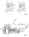
- Fig. 7 is a configuration diagram showing a connecting state between a pressure-reducing device for reducing a pressure in the switch case of the neutral start switch 1 and the neutral start switch 1 according to the present embodiment.
- a coupler 72 is fitted in a spigot joint manner in either one of the holes 19 and 49 as communicating openings of the neutral start switch 1.
- the coupler 72 is mounted to one end portion of a resisting pressure pipe, and the other of the pressure pipe is jointed to the pressure-reducing device.
- the pressure-reducing device comprises a pressure-reducing pump 70, such as a vacuum pump capable of reducing pressures, and a pressure-reducing line (for example, an exhaust pipe) 71 composed of the resisting pressure pipe, and the pressure-reducing pump 70 is connected to the downstream side of the pressure-reducing line 71.
- the coupler 72 comprises a fitting portion 73 fitted in the boss portion 48 or 18 of the neutral start switch 1 in a spigot joint manner, and a seal ring 75 mounted to the fitting portion 73, wherein the coupler 72 is configured to be sealed by flexible deformation of the seal ring 75 provided between a seating surface of the boss portion 48 or 18 and a seating surface of the coupler 72.
- the pressure-reducing line 71 is provided with a pressure gauge 76 interposed therein, such as a Pirani gauge upstream of the cutoff valve 77 for measuring the pressure in the switch case 3 through the pressure-reducing line 71.
- the seating surface of the boss portion 48 or 18 on which the coupler 72 is seated through the seal ring 75 is formed as a mirror surface having a surface roughness of Rz 6.3 ( ⁇ m) or less by JIS standards by mirror finish for establishing air-tight properties between the seating surface and the seal ring 75 seated on the seating surface.
- a pressure control valve may be provided in the pressure-reducing line 71 whereby, when a pressure in the switch case 3 is reduced to a pressure equal to or less than an atmospheric pressure, the cutoff valve 77 is closed to operate a notifying device for notifying it of an operator, thus realizing the automation.
- Figs. 8A to 8C show the pressure-reducing process.
- Fig. 8A shows a state of the mount finish of the pressure-reducing device.
- Fig. 8B shows the pressure-reducing state of the pressure-reducing device.
- Fig. 8C shows the finish state of the pressure-reducing process.
- the fitting portion 73 of the coupler 72 is fitted in either one of the boss portions 48 and the 18 in a spigot joint manner.
- the air-tight properties are maintained with the flexible deformation of the seal ring 75 by pressing the seal ring 75 against the seating surface of the boss portion 48 or 18.
- the cutoff valve 77 is opened while maintaining this state to discharge the air in the switch case 3 from the switch case 3, thus reducing the pressure in the switch case 3 to a predetermined pressure which can suppress the leakage of the grease, for example, a pressure of -100 (KPa).
- the pressure-reducing pump 70 is activated by a start switch (not shown) and the cutoff valve 77 is operated to open manually or by an operating signal from a meter relay (not shown) of a pressure meter or a controller (not shown).
- a start switch not shown
- the cutoff valve 77 is operated to open manually or by an operating signal from a meter relay (not shown) of a pressure meter or a controller (not shown).
- the seal ring 75 makes tight contact with the seating surface of the boss portion 48 and the seating surface of the coupler 72 makes tight contact with the seal ring 75.
- the coupler 72 is made to stick to the boss portion 48 through the seal ring 75. In this state the sealing state is maintained even if an operator releases its hands from the coupler 72.
- the air in the switch case 3 reaches through the communicating opening 81 (refer to Fig. 4 ) formed of the hole or the notch in the sub seal portion 47c, the shaft hole 45, the hole 49 of the boss portion 48 and the pressure-reducing line 71 to the suction portion of the pressure-reducing pump 70, and is discharged to an atmosphere from the discharging port (not shown) of the pressure-reducing pump 70. Therefore the pressure in the switch case 3 is gradually reduced.
- the cutoff valve 77 is closed manually or automatically by the control of the controller (not shown) based upon a detection value of the meter relay in the pressure meter 76 or of a pressure sensor (not shown).
- the seal portion 47b makes tight contact with the rotary surface of the upper shaft portion 57 by a difference between the atmospheric pressure and the pressure in the switch case 3 and by the flexible force of the seal portion 47b itself to seal the switch case 3.
- the air-tight inspection is implemented as the inspection process before shipment of a finished product, which is a process in the downstream side of the manufacturing process.
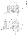
- Fig. 9A, Fig. 9B and Fig. 9C are diagrams showing verification of an internal pressure in the switch case in the pressure-reducing process, wherein Fig. 9A shows a state of an internal pressure immediately after the assembly, and Fig. 9B shows a state of an internal pressure after the pressure-reducing. Fig. 9C shows an example of an inspection method of confirming the pressure-reducing effect.
- the inspection device is, as shown in Fig. 9C , configured by a plug 78 connected to the connector portion 5 and a pressure meter 80 for detecting a pressure between the plug 78 and the connector portion 5.
- a pressure meter 80 for detecting a pressure between the plug 78 and the connector portion 5.
- the determination may be made by reading the pressure meter 76 by a responsible person of inspection, but in the present embodiment, when the meter relay (not shown) of the pressure meter 80 becomes a set value, for example, when the pressure of the aforementioned pressure-reducing process becomes a predetermined pressure which can suppress the leakage of the grease , for example, a pressure value equal to or less than an atmospheric pressure, the meter relay sends a signal that the verification result is normal, to the controller (not shown), which outputs the inspection result to a display device.
- the meter relay when the pressure in the switch case 3 reaches the set value (for example, -100KPa) equal to or less than an atmospheric pressure, the meter relay is operated and sends, as a signal, information that the pressure in the switch case 3 is below the atmospheric pressure to the controller.
- the set value for example, -100KPa
- the controller when this signal is outputted, that is, when the pressure in the switch case 3 reaches the set value equal to or less than the atmospheric pressure, sends a signal that the verification result is normal (acceptable) to the display device, for example, a signal lamp, a display or a notifying device.
- the display device for example, a signal lamp, a display or a notifying device.
- the controller turns on, for example, the signal lamp in blue.
- the controller selects, for example, a chime sound as a signal corresponding to the inspection acceptance, which is outputted to the notifying device.
- the controller displays a display of the inspection acceptance on the display.
- the controller outputs a signal of the inspection failure to the display device.
- the display device is the lamp device
- the controller turns on the lamp device in red.
- the controller selects a buzzer sound for outputting.
- the controller displays the display of the inspection failure.
- the neutral start switch 1 comprises the substrate 10, the lid body 35 overlapping the substrate 10 to be jointed integrally with each other, the switch case 3 formed of the substrate 10 and the lid body 35, the seal ring 31 interposed between the overlapping surfaces of the substrate 10 and the lid body 35 to seal the space between the overlapping surfaces by flexible deformation of the seal ring 31, the movable board 50 arranged in the switch case 3 and rotatably arranged between the substrate 10 and the lid body 35, the movable contact points 54 arranged on the opposing surface of the movable board 50 to the substrate 10, the fixed contact points 20 provided on the opposing portions of the substrate 10 to the movable contact points 54 to be electrically connected to/disconnected from the movable contact points 54 with rotation of the movable board 50, the connecting piece portion 21 formed integrally with the fixed contact point 20 and extending inside the substrate 10 through insert molding to the substrate 10 to be exposed to an outside as the terminal of the connector portion 5 in the side wall 12 of the substrate 10 , the
- the pressure in the switch case 3 can be reduced to a pressure equal to or less than a predetermined pressure through the discharging opening 47d, the phenomenon that the grease is pushed out along the connecting piece portion 21 to the connector portion 5 is prevented, therefore preventing occurrence of the secondary harmful effect.
- the concave portion 47e is provided between the backside of the seal portion 47b and the body portion 47a for promoting a flexible deflection of the seal portion 47b. Therefore the seal portion 47b is opened by a difference between the negative pressure acting on the seal portion 47b through shaft hole 45 or 15 and the pressure in the switch case 3 to certainly form the discharging opening 47d. Therefore the sealed switch has high reliability.
- the concave portion 47e is preferably provided across the entire circumference.
- At least one sub seal portion 47c is provided in the body portion 47a at the side of the switch case 3, which forms a labyrinth-shaped seal regularly making flexible contact with the rotary surface and cooperating with the seal portion 47b, and the communicating opening 18 formed of the hole or the notch is formed in the sub seal portion 47c for passing the air in the switch case 3 into the side of the seal portion (main seal portion) 47b closer to the shaft hole.
- passing the air in the switch case 3 into the side of the seal portion (main seal portion) 47b closer to the shaft hole” means " when the discharging opening 47d is formed, the air in the switch case 3 is discharged between the seal portion 47b and the sub seal portion 47c, which is discharged from the discharging opening 47d to the shaft hole” , and means " in a case where the plural sub seal portions 47c are provided to be neighbored to each other, the air in the switch case 3 is discharged between the most downstream sub seal portion 47c and the seal portion 47b through the communicating openings 81 of the plural sub seal portions 47c in order from the upstream side to the downstream side and is discharged from the discharging opening 47d to the shaft hole” . Therefore the labyrinth-shaped seal is formed as a whole to prevent the sudden blowout of the air in the switch case 3.
- the shaft hole and the boss portion (48 or 18) having the communicating opening are formed in at least one of the lid body 35 and the substrate 10, and the boss portion (48 or 18) is formed in a columnar shape to be connected in a spigot joint manner to the coupler 72 connected to the pressure-reducing device (pressure-reducing pump 70 and the pressure-reducing line 71) for reducing the pressure in the switch case 3.
- the seal ring 75 is interposed between the seating surfaces of the coupler 72 and the boss portion (48 or 18) for sealing the space between the seating surfaces, and the seating surface of the boss portion (48 or 18) to the seal ring 75 is formed as the mirror surface, preferably the mirror surface of Rz 6.3 ( ⁇ m) or less.
- the sealed switch is configured as above to form the seating surface of the boss portion (48 or 18) as the mirror surface, the tight contact properties of the seal ring 75 are improved to improve the air-tight properties.
- the suction of air from an outside at the pressure-reducing of the switch case 3 is blocked by the seal ring 75 and the coupler 72 adheres through the seal ring 75 to the seating surface of the boss portion (48 or 18) and the seating surface of the coupler 72, the pressure in the switch case 3 is reduced.
- the coupler 72 is fitted in the boss portion (48 or 18) in a spigot joint, and the coupler 72 is jointed to the pressure-reducing device.
- the pressure in the switch case 3 is reduced to the predetermined pressure or less by the pressure-reducing device while maintaining the spigot joint of the coupler 72 to the boss portion (48 or 18), and a signal of finish of the pressure reduction is outputted to the display device for display.
- the predetermined pressure means a pressure which can suppress the leakage of the grease from the switch case 3.
- the finish of the pressure reduction is displayed on the display device. Therefore when the finish of the pressure reduction is displayed on the display device, the coupler 72 is removed from the sealed switch and the pressure reduction to a different sealed switch will be performed.
- the explanation is made in such a manner that at least the tip end portion of the sub seal portion 47c regularly makes flexible contact with the rotary surface of the upper shaft portion 57 or the lower shaft portion 58, the communicating opening 81 formed of the hole or the notch is formed in the sub seal portion 47c, and at the pressure-reducing of the switch case 3, the labyrinth seal is formed (refer to Fig. 4 ).
- the communicating opening 18 is not formed in the sub seal portion 47c, and instead, an axial length of the sub seal portion 47c may be shortened to form a gap between the rotary surface of the upper shaft portion 57 or the rotary surface of the lower shaft portion 58 and the sub seal portion 47c, thereby forming the labyrinth seal.
- the explanation is made in such a manner that the leakage of the grease is suppressed by reducing the pressure in the switch case 3 to the predetermined pressure, that is, a pressure equal to or less than an atmospheric pressure, but as long as the predetermined pressure is a pressure which can suppress the leakage of the grease, the predetermined pressure may be a pressure, for example, equal to or less than 12 KPa.
- the pressure in the switch case 3 can be made to the pressure which can suppress the leakage of the grease.
- the effect similar to that of the aforementioned embodiment can be achieved.
- the ring groove 30 for accommodating the seal ring 31 is provided on the top end surface 25 of the side wall 12 in the substrate 10, there is no possibility that the seal ring 31 drops at the time of pressing the lid body 35 onto the substrate 10,leading to the easy assembly.
- the top end surface 25 of the side wall 12 in the substrate 10 corresponds to the end surface of the side wall 12 and corresponds to the overlap surface of the substrate 10 in the aspect of the present invention.
- the lower surface 38a of the flange portion 38 in the lid body 35 corresponds to the overlap surface of the lid body 35.
- the ring groove 30 is arranged closer to the inside than the concave streak portion 26, but since the ring groove 30 has no affection on the sealing function of the switch case 3 by the seal ring 31, the ring groove 30 may be arranged closer to the outside than the concave streak portion 26.
- the lid body 35 has the side wall 37, and the lower surface 38a of the flange portion 38 spreading from the lower edge of the side wall 37 is formed as the overlap surface facing the top end surface 25 of the side wall 12 in the substrate 10, functions as a seal surface making contact with the seal ring 31, and is formed as a portion of providing the projecting streak portion 40.
- a peripheral edge portion of the lower surface of the lid body 35 may be formed as the overlap surface.
- the welding inclination surface 27 is formed in the concave streak portion 26 and the welding shoulder portion 41 is formed in the projecting streak portion 40, but the present invention is not limited thereto, and as long as the welding between a part of the lid body 35 and a part of the substrate 10 is made possible by interference with each other, any shape may be adopted.
- the welding shoulder portion may be formed in the concave streak portion 26, and the welding inclination surface may be formed in the projecting streak portion 40.
- the projecting streak portion 40 may be provided in the substrate 10, and the concave streak portion 26 may be provided in the lid body 35.
- the ring groove 30 for accommodating the seal ring 31 is provided on the top end surface 25 of the side wall 12 in the substrate 10, but as needed, the ring groove 30 may be formed on the opposing surface of the lid body 35, and the top end surface 25 of the substrate 10 may be formed as the seal surface.
- the present invention is high in convenience and effective in a case of being applied, particularly to a neutral start switch for a vehicular automatic transmission. While only the selected embodiment has been chosen to illustrate the present invention, it will be apparent to those skilled in the art from this disclosure that various changes and modifications can be made therein without departing from the scope of the invention as defined in the appended claims. Furthermore, the foregoing description of the embodiment according to the present invention is provided for illustration only, and not for the purpose of limiting the invention as defined by the appended claims and their equivalents.
Landscapes
- Engineering & Computer Science (AREA)
- General Engineering & Computer Science (AREA)
- Mechanical Engineering (AREA)
- Rotary Switch, Piano Key Switch, And Lever Switch (AREA)
- Switch Cases, Indication, And Locking (AREA)
Abstract
Description
- This application claims priority under 35 USC 119 from Japanese Patent Application No.
114000/2012 filed on May,15 2012 - The present invention relates to a sealed switch and a method for reducing an internal pressure in the sealed switch.
- There is known a neutral start switch (inhibitor switch) mounted on a vehicle to be used for detection of a selection range of a shift lever, as an example of this kind of sealed switch.
-
Fig. 10 shows a typical configuration of the neutral start switch. Theneutral start switch 1 is configured such that aswitch case 3 is formed of a plastic substrate 10 (polar substrate) and alid body 35. Fixedcontact points 20 of theneutral start switch 1 are mounted on thesubstrate 10 by insert molding, andmovable contact points 54 which are connected to/disconnected from thefixed contact points 20 are arranged in amovable board 50 movably arranged in theswitch case 3. Themovable board 50 is rotatably supported through ashaft portion 55 toseal bearings 67 inserted intoshaft holes lid body 35 and thesubstrate 10. Thesubstrate 10 is formed in a fan shape on the basis of theshaft holes - The
fixed contact points 20 are specifically mounted to a plurality of rows of arc-shaped fixed-contactpoint mount portions 68 around theshaft holes movable contact point 54 is connected to/disconnected from thefixed contact point 20 with rotation of themovable board 50 around theshaft holes fixed contact point 20 and themovable contact point 54 to be electrically connected/disconnected, which thus performs the switching operation. - The
fixed contact point 20 and themovable contact point 54 are coated with contact point grease for improving durability thereof and current-carrying properties at the contacting thereof. Thefixed contact point 20 is provided with a connectingpiece portion 21 integral therewith, and the connectingpiece portion 21 is formed to be integral with thesubstrate 10 by insert molding as described above. The connectingpiece portion 21 extends toward aconnector portion 5 inside thesubstrate 10 and is exposed to an outside as a terminal of theconnector portion 5 projecting from an outer surface of aside wall 12 of thesubstrate 10 to an outside. - The
neutral start switch 1 is provided withseal bearings 67 between theshaft portion 55 of themovable board 50 and theshaft holes switch case 3. In addition, thesubstrate 10 and thelid body 35 are air-tightly jointed with each other across the entire circumference of thesubstrate 10 and thelid body 35 by welding, and a seal ring (described later) is provided between joint surfaces of thesubstrate 10 and thelid body 35. - In a case of jointing the
substrate 10 and thelid body 35 in theneutral start switch 1 by welding, a high joint strength is necessary. Therefore conventionally a share joint method excellent in the welding performance and a welding structure suitable for the share joint method are adopted. -
Figs. 11A and 11B and Figs. 12C and 12D respectively show a welding structure (joint structure) between thesubstrate 10 and thelid body 35 in theneutral start switch 1 applied to the share joint method. - As shown in
Fig. 11A , thesubstrate 10 is provided with aside wall 12 surrounding an entire circumference of themovable board 50 in a rotation region thereof and formed integrally with thesubstrate 10, and aring groove 30 for accommodating theseal ring 31 and aconcave streak portion 26 are formed on atop end surface 25 of theside wall 12 across the entire circumference of theside wall 12 in that order from the inside. Awelding inclination surface 27 is formed in the depth of theconcave streak portion 26 of theside wall 12 at an outer peripheral side. In addition, thelid body 35 is provided with aprojecting streak portion 40 on alower surface 38a of aflange portion 38 in thelid body 35 opposing thetop end surface 25 of theside wall 12. The projectingportion 40 is fitted in theconcave streak portion 26 of theside wall 12. - The
projecting streak portion 40 extends across the entire circumference along a peripheral edge of theflange portion 38. Awelding shoulder portion 41 for welding with thewelding inclination surface 27 is formed in an intermediate portion of theprojecting streak portion 40 at the outer peripheral side thereof. Thewelding inclination surface 27 and thewelding shoulder portion 41 are configured such that when thetop end surface 25 of theside wall 12 makes contact with thelower surface 38a of thelid body 35, thewelding shoulder portion 41 of theprojecting streak portion 40 is designed to interfere with thewelding inclination surface 27 of theconcave streak portion 26. As a result, when high-frequency welding causes the melting of the interference portion across the entire circumference, theprojecting streak portion 40 and theside wall 12 are welded to be integral. - At the welding between the
substrate 10 and thelid body 35, when the projecting portion streak 40 of thelid body 35 is in the process of being inserted into theconcave streak portion 26 of thesubstrate 10 while interposing themovable board 50 between thesubstrate 10 and thelid body 35, as shown inFig. 11 B a corner of thewelding shoulder portion 41 of theprojecting streak portion 40 first makes contact with thewelding inclination surface 27 of theconcave streak portion 26. In this state a gap S1 remains between thetop end surface 25 of theside wall 12 and thelower surface 38a of thelid body 35. Thering groove 30 has a depth smaller than a diameter of theseal ring 31 in a free state (no load state), and theseal ring 31 partly projects from thering groove 30. - As the
lid body 35 is further pressed to thesubstrate 10 from a position ofFig. 11 B in the high-frequency applied state, the interference (overlap) portion between thewelding shoulder portion 41 and thewelding inclination surface 27 is melted, and thelid body 35 moves in the approaching direction relatively to thesubstrate 10. In addition, as shown inFig. 12C after thelower surface 38a of thelid body 35 makes contact with theseal ring 31 in thering groove 30, it presses theseal ring 31, and finally, as shown inFig. 12D , thelower surface 38a of thelid body 35 is seated on thetop end surface 25. Then theprojecting streak portion 40 and theside wall 12 are jointed across the entire circumference by welding, and along with it, the inside of theswitch case 3 becomes in a sealing condition by flexible deformation of theseal ring 31 between theside wall 12 and thelower surface 38a of thelid body 35. - In such a welding structure, however, the
neutral start switch 1 is sealed by the sealing operation across the entire circumference of theseal ring 31, but there are some cases where theconnector portion 5 gets wet with grease. In this situation, there is a possibility that durability of thefixed contact point 20 and themovable contact point 54 is degraded, and in some cases the leak of the grease itself takes for the event that water exists inside theneutral start switch 1. Further, there is a problem that the outside appearance and visual quality of theneutral start switch 1 get worse since dusts adhere to the leaked grease. - The inventors have found out the following matter as a result of repeatedly diligently studying factors of this leakage of the grease.
- (1) The leak of the grease can not be confirmed near the
seal ring 31. - (2) As the pressure in the
switch case 3 is measured, it is raised to pressures equal to or more than an atmospheric pressure. - That is, in the joint structure of the
substrate 10 and thelid body 35, since an inner space of theswitch case 3 interposed between thesubstrate 10 and thelid body 35 starts to be blocked out from the outside from the position shown inFig. 11 B , the inner space is compressed by the gap S1 caused by the pushing movement of thelid body 35 during a period from the position inFig. 11 B to the joint completion shown inFig. 12D . As a result, thewelding shoulder portion 41 and thewelding inclination surface 27 are welded with each other to increase the welding amount. During this period, the sealing operations between the shaft portion of themovable board 50 and theshaft holes seal bearings 67, and the air inside theswitch case 3 is not released to an atmosphere because of each structure of theswitch case 3 and the seal bearing 67. Accordingly, it is estimated that the grease applied to thefixed contact point 20 in thesubstrate 10 is pushed out to the side of theconnector portion 5 by the pressure in theswitch case 3 after the welding between thesubstrate 10 and thelid body 35. - Accordingly, as described above, in the switch configured to form the sealed structure by interposing the
seal ring 31 between the joint surfaces of thelid body 35 and thesubstrate 10, a hole for releasing the pressure in theswitch case 3 is necessary. - It should be noted that Japanese Patent No.
3956433 switch case 3. - However, there occur problems that since the multi-hole semi transparent film is high in costs, it is difficult to adopt, since not only the multi-hole transparent film but also a film is exposed to an outside, it is susceptible to damages and the breathing is possibly difficult because of contamination of grease or the like, and at the time of picking switches and inspecting all of them, the measurement of internal pressures thereof is difficult because of difficulty in pressure measurement in the switch case through the breathing hole. In addition, for providing a hole of releasing a pressure in a plastic product, a change in a manufacturing line or an inspection line in regard to a mold, a line, an inspection or the like for the product is necessary, thereby creating a problem of increasing costs.
- Therefore in the sealed switch, it is required to release a pressure inside the switch case without changing or modifying the structure thereof as much as possible.
- Accordingly, the present invention is made in view of the above-described problems, and an object of the present invention is to provide a sealed switch which prevents water, mud and the like from entering into a switch case and at the same time, reduces a pressure in the switch case for preventing leakage of grease into a connector portion.
- According to an aspect of the present invention, a sealed switch comprises a substrate, a lid body overlapping the substrate to be jointed integrally with each other, a switch case formed of the substrate and the lid body, a seal ring provided between overlapping surfaces of the substrate and the lid body to seal a space between the overlapping surfaces by flexible deformation of the seal ring, a movable board arranged in the switch case and rotatably arranged between the substrate and the lid body, movable contact points arranged on an opposing surface of the movable board to the substrate, fixed contact points provided on opposing portions of the substrate to the movable contact points to be electrically connected to/disconnected from the movable contact points with rotation of the movable board, a connecting piece portion formed integrally with the fixed contact point and extending inside the substrate by insert molding to the substrate to be exposed to an outside as a terminal of a connector portion in a side wall of the substrate, an upper shaft portion and a lower shaft portion provided in a shaft portion of the movable board to rotatably support the shaft portion of the movable board to the substrate and the lid body, shaft holes formed in the substrate and the lid body to rotatably support the upper shaft portion and the lower shaft portion through seal bearings respectively, and communicating openings provided in the substrate and the lid body to communicate the shaft holes with an outside, wherein
at least one of the seal bearings includes a cylindrical body portion fitted in one of the shaft holes, and a lip-shaped seal portion provided in a lip shape on an inner peripheral surface of the body portion and making flexible contact with a rotary surface of the upper shaft portion or the lower shaft portion opposing the seal portion to seal an inside of the switch case, wherein the seal portion is flexibly separated from the rotary surface by a difference between a pressure in the communicating opening side reduced through the communicating opening and the shaft hole communicated with the communicating opening and a pressure in the switch case to form a discharging opening between the rotary surface and the seal portion for discharging an air in the switch case. - In the sealed switch according to the aspect of the present invention, since the pressure in the switch case can be reduced by discharging the air in the switch case, the leakage of the grease applied to the fixed contact point from the connector portion can be prevented. Therefore occurrence of the secondary harmful effect due to the leakage of the grease can be prevented to largely improve the reliability. In addition, since the substrate and the lid body are sealed by the seal ring, the entering of water components or dusts into the switch case can be prevented. Further, it is possible to manufacture the seal switch with easiness and at low costs, which leads to a reduction of costs as a whole.
- Other objects, features, and advantages of the present invention will become more apparent from the following detailed description made with reference to the accompanying drawings, in which like parts are designated by like reference numbers and in which:
-
Fig. 1 is a perspective view showing an outside appearance of a neutral start switch according to an embodiment in the present invention; -
Fig. 2 is a cross section taken along an A plane inFig. 1 ; -
Fig. 3 is a plan view showing a substrate with a lid body being removed from the neutral start switch according to the embodiment; -
Fig. 4A and Fig. 4B are broken cross sections each showing a relation between shaft portions of a movable board and seal bearings according to the embodiment; -
Fig. 5A and Fig. 5B are cross sections each showing a detailed key part of a welding structure (joint structure) of the substrate and the lid body applied to the welding of the neutral start switch according to the embodiment; -
Fig. 6C and Fig. 6D are cross sections each showing the detailed key part of the welding structure (joint structure) of the substrate and the lid body applied to the welding of the neutral start switch according to the embodiment; -
Fig. 7 is a configuration diagram showing a pressure-reducing device for reducing a pressure in a switch case according to the embodiment; -
Fig. 8A, Fig. 8B and Fig. 8C are explanatory diagrams respectively showing a state before reducing the pressure, a state of reducing the pressure and a state after reducing the pressure in the switch case according to the embodiment; -
Fig. 9A, Fig. 9B and Fig. 9C are explanatory diagrams each showing a state of verification for an internal pressure in the sealed switch in the pressure-reducing process according to the embodiment; -
Fig. 10 is a cross section showing a typical configuration of a conventional neutral start switch; -
Fig. 11A and Fig. 11B are cross sections each showing a detailed key part of a welding structure (joint structure) of a substrate and a lid body applied to the welding of the conventional neutral start switch; and -
Fig. 12C and Fig. 12D are cross sections each showing the detailed key part of the welding structure (joint structure) of the substrate and the lid body applied to the welding of the conventional neutral start switch. - Hereinafter, a sealed switch according to an embodiment in the present invention will be explained by taking a neutral start switch (inhibitor switch) mounted on a vehicle to be used for detection of a selection range of a shift lever, as an example.
Fig. 1 is a perspective view showing an outside appearance of a neutral start switch according to the embodiment.Fig. 2 is a cross section taken along an A plane inFig. 1 .Fig. 3 is a plan view showing a substrate as viewed from a lid body side. - By referring to
Fig. 1 to Fig. 3 , theneutral start switch 1 is provided with aswitch case 3 formed of aplastic substrate 10 and alid body 35, each being made of a non-conductive plastic material excellent in heat resistance properties. Fixed contact points 20 (20a to 20i) are arranged on thesubstrate 10 called a polar board, and amovable board 50 provided with movable contact points 54 is accommodated in theswitch case 3. Thesubstrate 10 comprises primarily abottom wall 11 provided with the fixed contact points 20 (20a to 20i), aside wall 12 rising from a peripheral edge of thebottom wall 11, and further, aconnector portion 5 extending outward of theside wall 12 from thebottom wall 11 and positioned outside of a region where thelid body 35 overlaps theside wall 12. - A
shaft hole 15 for accommodating ashaft portion 55 of themovable board 50 is provided in thebottom wall 11 of thesubstrate 10 toward the outward from the inside, and a cylindricalseal receiving portion 16 enlarged in a diameter is provided in the inner end of theshaft hole 15 at the open side thereof. A ringshaped seal bearing 47 is held in theseal receiving portion 16. Thebottom wall 11 is formed in a fan shape on the basis of theshaft hole 15, and the fixed contact points 20 (20a to 20i) are insert-molded on a plurality of rows arcs around theshaft hole 15. Each fixed contact point 20 (20a to 20i), as shown inFig. 2 , integrally has a connectingpiece portion 21 extending to theconnector portion 5. The connectingpiece portion 21 is embedded in thebottom wall 11 by insert molding, and a tip end of the connectingpiece portion 21 forms part of a terminal 22 in theconnector portion 5, which is exposed to an outside. It should be noted that, as shown inFigs.1 and3 ,mount portions 6 are formed in thesubstrate 10 outside of a region where thelid body 35 overlaps thesubstrate 10 for mounting theneutral start switch 1 on an automatic transmission (not shown), and a metallic collar is embedded in each of themount portions 6 and is provided with along hole 66 for mounting the automatic transmission (not shown). - The
lid body 35 is formed in a fan shape corresponding to thebottom wall 11 of thesubstrate 10, and has aflange portion 38 opposing atop end surface 25 of theside wall 12 in thesubstrate 10 at the lower edge of aside wall 37 surrounding the peripheral edge of anupper wall 36. Theflange portion 38 has alower surface 38a which serves as a seal surface making contact with aseal ring 31, which will be described later, arranged on thetop end surface 25 to seal theswitch case 3, and is provided with a projectingstreak portion 40 formed to correspond to a concave streak portion 26 (refer toFig. 5 ), which will be described later, of thesubstrate 10. A welding shoulder portion 41 (refer toFig. 5 ) is formed in the intermediate portion in the height direction of the projectingstreak portion 40 at the outer peripheral side thereof. - The
upper wall 36 of thelid body 35 is provided with ashaft hole 45 to correspond to theshaft hole 15 of thebottom wall 11, and theshaft hole 45 is provided from the inside to the outward to accommodate theshaft portion 55 of themovable board 50. Aseal receiving portion 46 enlarged in a diameter is provided in the inner end of theshaft hole 45 at the opening side thereof. A ringshaped seal bearing 47 (described later) is retained in theseal receiving portion 46. - A
boss portion 18 is formed on an outer surface of thebottom wall 11 in thesubstrate 10 to correspond to theshaft hole 15, and aboss portion 48 is formed also on an outer surface of theupper wall 36 in thelid body 35 to correspond to theshaft hole 45. Theshaft hole 15 does not extend to an outer end of theboss portion 18, and ahole 19 is formed in theboss portion 18 to be coaxial with theshaft hole 15. Thehole 19 has a diameter slightly smaller than that of theshaft hole 15, and larger than that of a throughhole 59, which will be described later, of theshaft portion 55. That is, the throughhole 59 is opened through thehole 19 to an outside. Similarly theshaft hole 45 does not extend to an outer end of theboss portion 48, and ahole 49 is formed in theboss portion 48 to be coaxial with theshaft hole 45. Thehole 49 has a diameter slightly smaller than that of theshaft hole 45, and larger than that of the throughhole 59. - The
movable board 50 comprises a contactpoint support portion 51 for supporting themovable contact point 54, and a movable board shaft portion (hereinafter called shaft portion) 55 integral with the contactpoint support portion 51. Theshaft portion 55 comprises astep portion 56 enlarged in a diameter, anupper shaft portion 57 extending upwards and alower shaft portion 58 extending downwards to interpose thestep portion 56 therebetween, wherein the contactpoint support portion 51 radially extends from thestep portion 56. Theshaft portion 55 is provided with the throughhole 59 penetrating from theupper shaft portion 57 to thelower shaft portion 58. Theshaft portion 55 is jointed to an arm (not shown) for rotating themovable board 50 in response to an operation of a shift lever (not shown). Therefore when themovable board 50 rotates in response to the operation of the shift lever, the fixed contact point 20 (20a to 20i) making contact with themovable contact point 54 is switched corresponding to a rotation position of themovable board 50. - A projecting
portion 39 is formed on the inner surface of theupper wall 36, which projects by a predetermined amount from a predetermined range corresponding to theseal receiving portion 46 around theshaft hole 45. Theupper shaft portion 57 and thelower shaft portion 58 of theshaft portion 55 extend on the same axial line, and are supported by theshaft hole 45 of thelid body 35 and theshaft hole 15 of thesubstrate 10, and the contactpoint support portion 51 is rotatable on a basis of theshaft portion 55 in theswitch case 3. The contactpoint support portion 51 is provided with movable contactpoint retaining holes 52 opened to face thebottom wall 11 of thesubstrate 10, and themovable contact point 54 accommodated in the movable contactpoint retaining hole 52 is provided to be urged against the fixed contact point 20 (20a to 20i) on thebottom wall 11 by aspring 53. It should be noted that a plurality of movable contact points 54 corresponding to a plurality of rows of the fixed contact points 20 (20a to 20i) are supported by the contactpoint support portion 51, but for simplification, only the singlemovable contact point 54 is illustrated inFig. 2 . The upper surface of the contactpoint support portion 51 is positioned to be slidable with the inner surface of theupper wall 36 at a radial outside of the projectingportion 39 in thelid body 35. - As described above, since the
hole 19 opened to theboss portion 18 of thesubstrate 10 is smaller in a diameter than theshaft hole 15 and thehole 49 opened to theboss portion 48 of thelid body 35 is also smaller in a diameter than theshaft hole 45, a rotary surface of the shaft portion 55 (upper shaft portion 57 and lower shaft portion 58) and an inner peripheral surface of each of the shaft holes 15 and 45 are hidden from an outside to prevent dusts or water from directly entering therebetween. Further, in the respective shaft holes 15 and 45, a seal structure to theupper shaft portion 57 and thelower shaft portion 58 of theshaft portion 55 is formed by theseal bearings 47 retained in theseal receiving portions switch case 3 from the rotary surface between theshaft portion 55 and each of the shaft holes 45 and 15. -
Fig. 4A and Fig. 4B are enlarged diagrams each showing a key part inFig. 2 showing theseal bearings 47.Fig. 4A shows a state where the seal bearing 47 is closed, andFig. 4B shows a state where the seal bearing 47 is opened. Theseal bearing 47 is made of a rubber material high in heat resistance properties and high in weather resistance properties. As shown inFig. 2 andFigs. 4A and 4B , the seal bearing 47 comprises acylindrical body portion 47a fitted in each of the shaft holes 45 and 15,theupper shaft portion 57 and each of theupper shaft portion 57 and thelower shaft portion 58, a lip-shapedseal portion 47b of a first stage (main seal portion) extending from an inner peripheral surface of thebody portion 47a to a rotary surface side of each of theupper shaft portion 57 and thelower shaft portion 58 to make flexible contact across an entire circumference with the rotary surface as an opposing surface of each of theupper shaft portion 57 and thelower shaft portion 58 for sealing, and a lip-shapedsub seal portion 47c of a second stage formed to be separated by an appropriate interval from thefirst seal portion 47b. - The
seal portion 47b is configured such that at least a tip end portion thereof regularly makes flexible contact with the rotary surface of theshaft portion 55 across an entire circumference to seal the rotary surface, and at the pressure-reducing time of theshaft hole 45, as shown inFig. 4B , theseal portion 47b is separated from the rotary surface of theupper shaft portion 57 due to a difference in pressure from the inside of theswitch case 3 to form a dischargingopening 47d of an air in theswitch case 3 between the rotary surface and theseal portion 47b. Therefore a base end portion of theseal portion 47b is arranged on the inner peripheral surface of thebody portion 47a at the switch case side, and the tip end portion of theseal portion 47b is arranged at the side of theshaft hole 45 on the inner peripheral surface of thebody portion 47a. - The
seal portion 47b according to the present embodiment is formed to be inclined to an axis center line direction of thebody portion 47a. In addition, theseal portion 47b is formed across an entire circumference of the inner peripheral surface of thebody portion 47a as a one-way valve (diaphragm valve) opened by a difference in pressure, and is turned up by a difference in pressure at the pressure-reducing time of theswitch case 3 by the pressure reduction of the neighboring shaft hole, for example, theshaft hole 45 or a suction force at the pressure-reducing to form the dischargingopening 47d. - A
concave portion 47e is formed between thebody portion 47a and theseal portion 47b. Theconcave portion 47e is provided across an entire circumference between the backside of theseal portion 47b and the inner peripheral surface of thebody portion 47a to promote the flexible deflection of theseal portion 47b for facilitating formation of the dischargingopening 47d, at the pressure-reducing of theshaft hole 45 due to a discharge through the shaft holes 45 and 15. In addition, thebody portion 47a is provided with asub seal portion 47c formed closer to the inside of theswitch case 3 than theseal portion 47b of the first stage. For configuring a labyrinth seal structure together with theseal portion 47b of the first stage, thesub seal portion 47c is provided to have an interval from theseal portion 47b, and is inclined in a direction opposite to a direction of theseal portion 47b to the inner peripheral surface of thebody portion 47a. - In an example shown in
Fig. 4A , thesub seal portion 47c, at least a tip end thereof is formed in a lip shape to regularly make flexible contact with the rotary surface of theupper shaft portion 57 or thelower shaft portion 58, and thesub seal portion 47c is provided with a communicatingopening 81 formed of a hole or a notch for passing the air in theswitch case 3 to the side of theseal portion 47b. As the communicatingopening 81 is formed in thesub seal portion 47c, at the pressure-reducing of the switch case 3 a labyrinth seal structure comprising sequentially the communicatingopening 81, a space between thesub seal portion 47c and theseal portion 47b and the dischargingopening 47d is formed for suppressing sudden blowout at the pressure-reducing. - Next, an explanation will be made of the welding (fusion welding) structure between the
substrate 10 and thelid body 35. The welding is performed by vibration welding or ultrasonic welding using ultrasonic vibration energy. In the present embodiment, an explanation will be made of a case of welding by a share joint method. -
Figs. 5A and 5B , andFigs. 6C and 6D are enlarged cross sections showing a joint portion between thesubstrate 10 and thelid body 35, and the welding process thereof. Theside wall 12 of thesubstrate 10 surrounds the entire circumference of thebottom wall 11 for closure, and theconcave streak portion 26 is formed across the entire circumference of theside wall 12 on thetop end surface 25. In addition, the projectingstreak portion 40 of thelid body 35 is provided on the lower surface as an overlap surface to thetop end surface 25 of theside wall 12. The projectingstreak portion 40 substantially surrounds the entire circumference of thelid body 35, and is fitted into theconcave streak portion 26 of theside wall 12, wherein the projectingstreak portion 40 and theside wall 12 are jointed by high-frequency welding to form theswitch case 3 with thesubstrate 10 and thelid body 35 integral with each other. The welding portion between thelid body 35 and thesubstrate 10 is the same as the structure shown inFig. 12D . - Prior to the welding between the
lid body 35 and thesubstrate 10, as shown inFig. 5A theside wall 12 of thesubstrate 10 surrounds the entire circumference of thebottom wall 11 for closure, and aring groove 30 for accommodating theseal ring 31 and theconcave streak portion 26 are formed across the entire circumference in order from the inside on the top end surface (overlap surface) 25 of theside wall 12. Awelding inclination surface 27 is formed in the depth portion of theconcave streak portion 26 of theside wall 12 at the outer peripheral side. - When the projecting
streak portion 40 of thelid body 35 is inserted into theconcave streak portion 26 of thesubstrate 10, first, as shown inFig. 5B a corner of thewelding shoulder portion 41 in the projectingstreak portion 40 makes contact with thewelding inclination surface 27 of theconcave streak portion 26 on the general section. Thereafter, as thelid body 35 is further pressed to thesubstrate 10, the interference portion between thewelding shoulder portion 41 and thewelding inclination surface 27 on the general section is welded to reduce a volume of the inner space formed between thelid body 35 and thesubstrate 10. Even in that case, since air in the inner space escapes to an outside as shown in an arrow, the pressure therein does not increase. - As shown in
Fig. 6C , as thelower surface 38a of theflange portion 38 makes contact with theseal ring 31 in theseal groove 30, the inner space formed between thelid body 35 and thesubstrate 10 is eventually blocked out from the outside by theseal ring 31. After that, as thelid body 35 is further pressed to thesubstrate 10, as shown inFig. 6D finally, thelower surface 38a of theflange portion 38 is seated on thetop end surface 25 of theside wall 12. Thereby the projectingstreak portion 40 and theside wall 12 are welded substantially across the peripheral edge to be certainly jointed, and theseal ring 31 is interposed in a compressed state between thelid body 35 and thesubstrate 10. As a result, the inside of theswitch case 3 is in a sealing state to an outside. - Next, a pressure-reducing method and an air-tight inspection method after the pressure-reducing will be explained as a manufacturing method of the
neutral start switch 1 according to the present embodiment. -
Fig. 7 is a configuration diagram showing a connecting state between a pressure-reducing device for reducing a pressure in the switch case of theneutral start switch 1 and theneutral start switch 1 according to the present embodiment. As shown inFig. 7 , at the time of reducing the pressure in theneutral start switch 1, for example, at the pre-process of the shipment, acoupler 72 is fitted in a spigot joint manner in either one of theholes neutral start switch 1. Thecoupler 72 is mounted to one end portion of a resisting pressure pipe, and the other of the pressure pipe is jointed to the pressure-reducing device. - The pressure-reducing device comprises a pressure-reducing
pump 70, such as a vacuum pump capable of reducing pressures, and a pressure-reducing line (for example, an exhaust pipe) 71 composed of the resisting pressure pipe, and the pressure-reducingpump 70 is connected to the downstream side of the pressure-reducingline 71. Thecoupler 72 comprises afitting portion 73 fitted in theboss portion neutral start switch 1 in a spigot joint manner, and aseal ring 75 mounted to thefitting portion 73, wherein thecoupler 72 is configured to be sealed by flexible deformation of theseal ring 75 provided between a seating surface of theboss portion coupler 72. - The pressure-reducing
line 71 is provided with apressure gauge 76 interposed therein, such as a Pirani gauge upstream of thecutoff valve 77 for measuring the pressure in theswitch case 3 through the pressure-reducingline 71. The seating surface of theboss portion coupler 72 is seated through theseal ring 75 is formed as a mirror surface having a surface roughness of Rz 6.3 (µm) or less by JIS standards by mirror finish for establishing air-tight properties between the seating surface and theseal ring 75 seated on the seating surface. It should be noted that a pressure control valve may be provided in the pressure-reducingline 71 whereby, when a pressure in theswitch case 3 is reduced to a pressure equal to or less than an atmospheric pressure, thecutoff valve 77 is closed to operate a notifying device for notifying it of an operator, thus realizing the automation. -
Figs. 8A to 8C show the pressure-reducing process.Fig. 8A shows a state of the mount finish of the pressure-reducing device.Fig. 8B shows the pressure-reducing state of the pressure-reducing device.Fig. 8C shows the finish state of the pressure-reducing process. In the pressure-reducing process of theneutral star switch 1, as shown inFig. 7 andFig. 8A , thefitting portion 73 of thecoupler 72 is fitted in either one of theboss portions 48 and the 18 in a spigot joint manner. At an initial period of the pressure-reducing process, the air-tight properties are maintained with the flexible deformation of theseal ring 75 by pressing theseal ring 75 against the seating surface of theboss portion cutoff valve 77 is opened while maintaining this state to discharge the air in theswitch case 3 from theswitch case 3, thus reducing the pressure in theswitch case 3 to a predetermined pressure which can suppress the leakage of the grease, for example, a pressure of -100 (KPa). - In the pressure-reducing process, the pressure-reducing
pump 70 is activated by a start switch (not shown) and thecutoff valve 77 is operated to open manually or by an operating signal from a meter relay (not shown) of a pressure meter or a controller (not shown). As described before, since the seating surface of theboss portion 48 is formed as the mirror surface and the surface of theseal ring 75 is made smooth, in a state where thecoupler 72 is pressed through theseal ring 75 on the seating surface of theboss portion 48, there is no gap between the seating surface of theboss portion 48 and the seating surface of thecoupler 72, and theseal ring 75. Therefore there is no possibility that outside air is suctioned from an outside. When the pressure-reducingpump 70 discharges the air in thehole 49, theshaft hole 45, thecoupler 72 and the pressure-reducingline 71 to reduce the pressure therein, theseal ring 75 makes tight contact with the seating surface of theboss portion 48 and the seating surface of thecoupler 72 makes tight contact with theseal ring 75. As a result, thecoupler 72 is made to stick to theboss portion 48 through theseal ring 75. In this state the sealing state is maintained even if an operator releases its hands from thecoupler 72. By the discharging operation of the pressure-reducingpump 70, a reduction in the pressure of each of the pressure-reducingline 71, the hole (communicating opening) 49 of theboss portion 48 and theshaft hole 45 is progressed, and a negative pressure exceeding the flexibility returning force of theseal portion 47b acts on the backside of theseal portion 47b through each of the pressure-reducingline 71, the hole (communicating opening) 49 of theboss portion 48 and theshaft hole 45. Then the seal portion (main seal portion) 47b is opened to form the dischargingopening 47d discharging the air in theswitch case 3 between the rotary surface of theupper shaft portion 57 and the tip end portion of theseal portion 47b. - When the discharging
opening 47d is formed, the air in theswitch case 3 reaches through the communicating opening 81 (refer toFig. 4 ) formed of the hole or the notch in thesub seal portion 47c, theshaft hole 45, thehole 49 of theboss portion 48 and the pressure-reducingline 71 to the suction portion of the pressure-reducingpump 70, and is discharged to an atmosphere from the discharging port (not shown) of the pressure-reducingpump 70. Therefore the pressure in theswitch case 3 is gradually reduced. When the pressure in theswitch case 3 is reduced for the detection pressure of thepressure meter 76 to reach a predetermined pressure equal to or less than the atmospheric pressure, for example, a pressure of -100 (KPa), thecutoff valve 77 is closed manually or automatically by the control of the controller (not shown) based upon a detection value of the meter relay in thepressure meter 76 or of a pressure sensor (not shown). In this state, as shown inFig. 8C , theseal portion 47b makes tight contact with the rotary surface of theupper shaft portion 57 by a difference between the atmospheric pressure and the pressure in theswitch case 3 and by the flexible force of theseal portion 47b itself to seal theswitch case 3. in a state where the pressure in theswitch case 3 is equal to or less than the atmospheric pressure, the movement of the grease, which is about to leak through the boundary between the connectingpiece portion 21 and the plastic (plastic of the substrate 10) from theconnector portion 5, to the side of theconnector portion 5 is stopped and in reverse, the grease returns to the inside of theswitch case 3 by the difference in the pressure. Therefore the leakage of the grease from theconnector portion 5 is prevented to eliminate the secondary harmful effects due to the leakage of the grease. That is, the erroneous recognition that water enters in theswitch case 3 and the grease starts to leak, a reduction in durability and short cut of the fixedcontact point 20 due to the leakage of the grease, and degradation in an outside appearance of theswitch case 3 due to dusts adhering to the leaked grease are eliminated to improve the function and reliability of the outside appearance as a finished product. - The air-tight inspection is implemented as the inspection process before shipment of a finished product, which is a process in the downstream side of the manufacturing process.
-
Fig. 9A, Fig. 9B and Fig. 9C are diagrams showing verification of an internal pressure in the switch case in the pressure-reducing process, whereinFig. 9A shows a state of an internal pressure immediately after the assembly, andFig. 9B shows a state of an internal pressure after the pressure-reducing.Fig. 9C shows an example of an inspection method of confirming the pressure-reducing effect. - The inspection device is, as shown in
Fig. 9C , configured by aplug 78 connected to theconnector portion 5 and apressure meter 80 for detecting a pressure between theplug 78 and theconnector portion 5. In the verification process of a pressure in theneutral start switch 1, when the pressure between theplug 78 and theconnector portion 5 is equal to or less than an atmospheric pressure, it is determined that theneutral start switch 1 can be shipped as a finished product. The determination may be made by reading thepressure meter 76 by a responsible person of inspection, but in the present embodiment, when the meter relay (not shown) of thepressure meter 80 becomes a set value, for example, when the pressure of the aforementioned pressure-reducing process becomes a predetermined pressure which can suppress the leakage of the grease , for example, a pressure value equal to or less than an atmospheric pressure, the meter relay sends a signal that the verification result is normal, to the controller (not shown), which outputs the inspection result to a display device. In the present embodiment, when the pressure in theswitch case 3 reaches the set value (for example, -100KPa) equal to or less than an atmospheric pressure, the meter relay is operated and sends, as a signal, information that the pressure in theswitch case 3 is below the atmospheric pressure to the controller. - The controller, when this signal is outputted, that is, when the pressure in the
switch case 3 reaches the set value equal to or less than the atmospheric pressure, sends a signal that the verification result is normal (acceptable) to the display device, for example, a signal lamp, a display or a notifying device. When the verification result is normal (acceptable), as shown inFig. 9B the grease is pulled back to the inside of theswitch case 3 and the leakage of the grease from theconnector portion 5 is prevented. In a case where the display device is a signal lamp showing blue and red colors, the controller turns on, for example, the signal lamp in blue. In a case where the display device is the notifying device, the controller selects, for example, a chime sound as a signal corresponding to the inspection acceptance, which is outputted to the notifying device. In a case where the display device is the display, the controller displays a display of the inspection acceptance on the display. In a case where a signal corresponding to the inspection acceptance is not outputted from the meter relay even after a predetermined time elapses, the controller outputs a signal of the inspection failure to the display device. In a case where the display device is the lamp device, the controller turns on the lamp device in red. In a case where the display device is the notifying device, the controller selects a buzzer sound for outputting. In a case where the display device is the display, the controller displays the display of the inspection failure. - As described above, the neutral start switch 1 according to the embodiment in the present invention comprises the substrate 10, the lid body 35 overlapping the substrate 10 to be jointed integrally with each other, the switch case 3 formed of the substrate 10 and the lid body 35, the seal ring 31 interposed between the overlapping surfaces of the substrate 10 and the lid body 35 to seal the space between the overlapping surfaces by flexible deformation of the seal ring 31, the movable board 50 arranged in the switch case 3 and rotatably arranged between the substrate 10 and the lid body 35, the movable contact points 54 arranged on the opposing surface of the movable board 50 to the substrate 10, the fixed contact points 20 provided on the opposing portions of the substrate 10 to the movable contact points 54 to be electrically connected to/disconnected from the movable contact points 54 with rotation of the movable board 50, the connecting piece portion 21 formed integrally with the fixed contact point 20 and extending inside the substrate 10 through insert molding to the substrate 10 to be exposed to an outside as the terminal of the connector portion 5 in the side wall 12 of the substrate 10 , the upper shaft portion 57 and the lower shaft portion 58 provided in the base portion (shaft portion 55) of the movable board 50 to rotatably support the movable board 50 to the substrate 10 and the lid body 35, the shaft holes 45 and 15 formed in the substrate 10 and the lid body 35 to rotatably support the upper shaft portion 57 and the lower shaft portion 58 through the seal bearings 47 respectively, and the communicating openings (holes 19 and 49) provided in the substrate 10 and the lid body 35 to communicate the shaft holes 45 and 15 with an outside, wherein
at least one of theseal bearings cylindrical body portion 47a fitted in one of the shaft holes 45 and 15, and the lip-shapedseal portion 47b provided in a lip-shaped manner on the inner peripheral surface of thebody portion 47a and making flexible contact with the rotary surface of theupper shaft portion 57 or thelower shaft portion 58 opposing theseal portion 47b to seal the inside of theswitch case 3, wherein theseal portion 47b is flexibly separated from the rotary surface by a difference between a pressure in the communicating opening (hole 49 or 19) side reduced through the communicating opening (hole 49 or 19) and the shaft hole (45 or 15) communicated with the communicating opening (hole 49 or 19) and a pressure in theswitch case 3 to form the dischargingopening 47d between the rotary surface and theseal portion 47b for discharging the air in theswitch case 3. According to theneutral start switch 1, since the pressure in theswitch case 3 can be reduced to a pressure equal to or less than a predetermined pressure through the dischargingopening 47d, the phenomenon that the grease is pushed out along the connectingpiece portion 21 to theconnector portion 5 is prevented, therefore preventing occurrence of the secondary harmful effect. - In the sealed switch, the
concave portion 47e is provided between the backside of theseal portion 47b and thebody portion 47a for promoting a flexible deflection of theseal portion 47b. Therefore theseal portion 47b is opened by a difference between the negative pressure acting on theseal portion 47b throughshaft hole switch case 3 to certainly form the dischargingopening 47d. Therefore the sealed switch has high reliability. Theconcave portion 47e is preferably provided across the entire circumference. - In the sealed switch, at least one
sub seal portion 47c is provided in thebody portion 47a at the side of theswitch case 3, which forms a labyrinth-shaped seal regularly making flexible contact with the rotary surface and cooperating with theseal portion 47b, and the communicatingopening 18 formed of the hole or the notch is formed in thesub seal portion 47c for passing the air in theswitch case 3 into the side of the seal portion (main seal portion) 47b closer to the shaft hole. Here, " passing the air in theswitch case 3 into the side of the seal portion (main seal portion) 47b closer to the shaft hole" means " when the dischargingopening 47d is formed, the air in theswitch case 3 is discharged between theseal portion 47b and thesub seal portion 47c, which is discharged from the dischargingopening 47d to the shaft hole" , and means " in a case where the pluralsub seal portions 47c are provided to be neighbored to each other, the air in theswitch case 3 is discharged between the most downstreamsub seal portion 47c and theseal portion 47b through the communicatingopenings 81 of the pluralsub seal portions 47c in order from the upstream side to the downstream side and is discharged from the dischargingopening 47d to the shaft hole" . Therefore the labyrinth-shaped seal is formed as a whole to prevent the sudden blowout of the air in theswitch case 3. - In the sealed switch, the shaft hole and the boss portion (48 or 18) having the communicating opening are formed in at least one of the
lid body 35 and thesubstrate 10, and the boss portion (48 or 18) is formed in a columnar shape to be connected in a spigot joint manner to thecoupler 72 connected to the pressure-reducing device (pressure-reducingpump 70 and the pressure-reducing line 71) for reducing the pressure in theswitch case 3. Further, theseal ring 75 is interposed between the seating surfaces of thecoupler 72 and the boss portion (48 or 18) for sealing the space between the seating surfaces, and the seating surface of the boss portion (48 or 18) to theseal ring 75 is formed as the mirror surface, preferably the mirror surface of Rz 6.3 (µm) or less. As the sealed switch is configured as above to form the seating surface of the boss portion (48 or 18) as the mirror surface, the tight contact properties of theseal ring 75 are improved to improve the air-tight properties. As a result, in a state where the suction of air from an outside at the pressure-reducing of theswitch case 3 is blocked by theseal ring 75 and thecoupler 72 adheres through theseal ring 75 to the seating surface of the boss portion (48 or 18) and the seating surface of thecoupler 72, the pressure in theswitch case 3 is reduced. - In the method for reducing the internal pressure in the aforementioned sealed switch, in a state where the
seal ring 75 is arranged on the seating surface of the boss portion (48 or 18), thecoupler 72 is fitted in the boss portion (48 or 18) in a spigot joint, and thecoupler 72 is jointed to the pressure-reducing device. Thereby the pressure in theswitch case 3 is reduced to the predetermined pressure or less by the pressure-reducing device while maintaining the spigot joint of thecoupler 72 to the boss portion (48 or 18), and a signal of finish of the pressure reduction is outputted to the display device for display. Here, the predetermined pressure means a pressure which can suppress the leakage of the grease from theswitch case 3. When the pressure in theswitch case 3 is equal to or less than the atmospheric pressure, the finish of the pressure reduction is displayed on the display device. Therefore when the finish of the pressure reduction is displayed on the display device, thecoupler 72 is removed from the sealed switch and the pressure reduction to a different sealed switch will be performed. - It should be noted that in the aforementioned embodiment, the explanation is made in such a manner that at least the tip end portion of the
sub seal portion 47c regularly makes flexible contact with the rotary surface of theupper shaft portion 57 or thelower shaft portion 58, the communicatingopening 81 formed of the hole or the notch is formed in thesub seal portion 47c, and at the pressure-reducing of theswitch case 3, the labyrinth seal is formed (refer toFig. 4 ). However, the communicatingopening 18 is not formed in thesub seal portion 47c, and instead, an axial length of thesub seal portion 47c may be shortened to form a gap between the rotary surface of theupper shaft portion 57 or the rotary surface of thelower shaft portion 58 and thesub seal portion 47c, thereby forming the labyrinth seal. In addition, in the embodiment, the explanation is made in such a manner that the leakage of the grease is suppressed by reducing the pressure in theswitch case 3 to the predetermined pressure, that is, a pressure equal to or less than an atmospheric pressure, but as long as the predetermined pressure is a pressure which can suppress the leakage of the grease, the predetermined pressure may be a pressure, for example, equal to or less than 12 KPa. When the predetermined pressure is reduced to the pressure equal to or less than this pressure, the pressure in theswitch case 3 can be made to the pressure which can suppress the leakage of the grease. As a result, the effect similar to that of the aforementioned embodiment can be achieved. In addition, since thering groove 30 for accommodating theseal ring 31 is provided on thetop end surface 25 of theside wall 12 in thesubstrate 10, there is no possibility that theseal ring 31 drops at the time of pressing thelid body 35 onto thesubstrate 10,leading to the easy assembly. - It should be noted that in the aforementioned embodiment, the
top end surface 25 of theside wall 12 in thesubstrate 10 corresponds to the end surface of theside wall 12 and corresponds to the overlap surface of thesubstrate 10 in the aspect of the present invention. In addition, thelower surface 38a of theflange portion 38 in thelid body 35 corresponds to the overlap surface of thelid body 35. - In the present embodiment, the
ring groove 30 is arranged closer to the inside than theconcave streak portion 26, but since thering groove 30 has no affection on the sealing function of theswitch case 3 by theseal ring 31, thering groove 30 may be arranged closer to the outside than theconcave streak portion 26. - In addition, in the present embodiment, the
lid body 35 has theside wall 37, and thelower surface 38a of theflange portion 38 spreading from the lower edge of theside wall 37 is formed as the overlap surface facing thetop end surface 25 of theside wall 12 in thesubstrate 10, functions as a seal surface making contact with theseal ring 31, and is formed as a portion of providing the projectingstreak portion 40. However, in a case where thelid body 35 is formed in a flat shape with no side wall, a peripheral edge portion of the lower surface of thelid body 35 may be formed as the overlap surface. - Further, the
welding inclination surface 27 is formed in theconcave streak portion 26 and thewelding shoulder portion 41 is formed in the projectingstreak portion 40, but the present invention is not limited thereto, and as long as the welding between a part of thelid body 35 and a part of thesubstrate 10 is made possible by interference with each other, any shape may be adopted. The welding shoulder portion may be formed in theconcave streak portion 26, and the welding inclination surface may be formed in the projectingstreak portion 40. - Further, the projecting
streak portion 40 may be provided in thesubstrate 10, and theconcave streak portion 26 may be provided in thelid body 35. In addition, thering groove 30 for accommodating theseal ring 31 is provided on thetop end surface 25 of theside wall 12 in thesubstrate 10, but as needed, thering groove 30 may be formed on the opposing surface of thelid body 35, and thetop end surface 25 of thesubstrate 10 may be formed as the seal surface. - The present invention is high in convenience and effective in a case of being applied, particularly to a neutral start switch for a vehicular automatic transmission.
While only the selected embodiment has been chosen to illustrate the present invention, it will be apparent to those skilled in the art from this disclosure that various changes and modifications can be made therein without departing from the scope of the invention as defined in the appended claims. Furthermore, the foregoing description of the embodiment according to the present invention is provided for illustration only, and not for the purpose of limiting the invention as defined by the appended claims and their equivalents. -
1 Neutral start switch 3 Switch case 5 Connector portion 6 Mount portion 10 Substrate 11 Bottom wall 12 Side wall 15 Shaft hole 18 Boss portion 19 Hole (communicating opening) 20 Fixed contact point 21 Connecting piece portion 22 Terminal 25 Top end surface 26 Concave streak portion 27 Welding inclination surface 30 Ring groove 31 Seal ring 35 Lid body 36 Upper wall 37 Side wall 38 Flange portion 38a Lower surface 39 Projecting portion 40 Projecting streak portion 41 Welding shoulder portion 45 Shaft hole 46 Seal receiving portion 47 Seal bearing 47a Body portion 47b Seal portion 47c Sub seal portion 47d Discharging opening 47e Concave portion 48 Boss portion 49 Hole (communicating opening) 50 Movable board 51 Contact point support portion 52 Movable contact point retaining hole 53 Spring 54 Movable contact point 55 Shaft portion 56 Step portion 57 Upper shaft portion 58 Lower shaft portion 59 Through hole 66 Long hole 67 Seal bearing 68 Fixed contact point mount portion 70 Pressure-reducing pump 71 Pressure-reducing line 72 Coupler 73 Fitting portion 74 Concave portion 75 Seal ring 76 Pressure meter 77 Cutoff valve 78 Plug 80 Pressure meter 81 Communicating opening S1 Gap
Claims (5)
- A sealed switch comprising:a substrate (10);a lid body (35) overlapping the substrate to be jointed integrally with each other;a switch case (3) formed of the substrate (10) and the lid body (35); a sealring (31) provided between overlapping surfaces of the substrate (10) and the lid body (35) to seal a space between the overlapping surfaces by flexible deformation of the seal ring (31);a movable board (50) arranged in the switch case (3) and rotatably arranged between the substrate (10) and the lid body (35);movable contact points (54) arranged on an opposing surface of the movable board (50) to the substrate (10);fixed contact points (20) provided on opposing portions of the substrate (10) to the movable contact points (54) to be electrically connected to/disconnected from the movable contact points with rotation of the movable board (50);a connecting piece portion (21) formed integrally with the fixed contact point (20) and extending inside the substrate (10) by insert molding to the substrate to be exposed to an outside as a terminal (22) of a connector portion (5) in a side wall of the substrate (10);an upper shaft portion (57) and a lower shaft portion (58) provided in a shaft portion (55) of the movable board (50) to rotatably support the shaft portion of the movable board to the substrate (10) and the lid body (35);shaft holes (15) formed in the substrate (10) and the lid body (35) to rotatably support the upper shaft portion (57) and the lower shaft portion (58) through seal bearings (47) respectively; andcommunicating openings (81) provided in the substrate (10) and the lid body (35) to communicate the shaft holes (15) with an outside, whereinat least one of the seal bearings (47) includes a cylindrical body portion (47a) fitted in one of the shaft holes (15), and a lip-shaped seal portion (47b) provided in a lip shape on an inner peripheral surface of the body portion (47a) and making flexible contact with a rotary surface of the upper shaft portion (57) or the lower shaft portion (58) opposing the seal portion (47b) to seal an inside of the switch case (3), wherein the seal portion (47b) is flexibly separated from the rotary surface by a difference between a pressure in the communicating opening side reduced through the communicating opening (81) and the shaft hole (15) communicated with the communicating opening (81) and a pressure in the switch case (3) to form a discharging opening (47d) between the rotary surface and the seal portion (47b) for discharging an air in the switch case (3).
- A sealed switch according to claim 1, wherein
a concave portion (47e) is provided between the backside of the seal portion (47b) and the body portion (47a) for promoting a flexible deflection of the seal portion. - A sealed switch according to claim 1 or 2, wherein
at least one sub seal portion (47c) is provided in the body portion (47a) at the side of the switch case (3) to regularly make flexible contact with the rotary surface and cooperate with the seal portion (47b) for forming a labyrinth-shaped seal, and
a communicating opening (49) formed of a hole or a notch is formed in the sub seal portion (47c) for passing the air in the switch case (3) into the side of the seal portion (47b) closer to the shaft hole (15). - A sealed switch according to any of claims 1 to 3, wherein
a boss portion (18) including the shaft hole (15) and the communicating opening (81) is formed in at least one of the lid body (35) and the substrate (10), and is formed in a columnar shape to be connected in a spigot joint manner to a coupler (72) connected to a pressure-reducing device (70, 71) for reducing the pressure in the switch case (3), and
a seal ring (75) is interposed between seating surfaces of the coupler (72) and the boss portion (48) for sealing a space between the seating surfaces, wherein the seating surface of the boss portion (48) to the seal ring (75) is formed as a mirror surface. - A method for reducing an internal pressure in a sealed switch comprising:a substrate;a lid body overlapping the substrate to be jointed integrally with each other;a switch case formed of the substrate and the lid body, a seal ringprovided between overlapping surfaces of the
substrate and the lid body to seal a space between the
overlapping surfaces by flexible deformation of the seal ring;a movable board arranged in the switch case and rotatably arranged between the substrate and the lid body;movable contact points arranged on an opposing surface of the movable board to the substrate;fixed contact points provided on opposing portions of the substrate to the movable contact points to be electrically connected to/disconnected from the movable contact points with rotation of the movable board;a connecting piece portion formed integrally with the fixed contact point and extending inside the substrate by insert molding to the substrate to be exposed to an outside as a terminal of a connector portion in a side wall of the substrate;an upper shaft portion and a lower shaft portion provided in a shaft portion of the movable board to rotatably support the shaft portion of the movable board to the substrate and the lid body;shaft holes formed in the substrate and the lid body to rotatably support the upper shaft portion and the lower shaft portion through seal bearings respectively; andcommunicating openings provided in the substrate and the lid body to communicate the shaft holes with an outside, whereina boss portion including the shaft hole and the communicating opening is formed in at least one of the lid body or the substrate, and is formed in a columnar shape to be connected in a spigot joint manner to a coupler connected to a pressure-reducing device for reducing the pressure in the switch case, anda seal ring is provided between seating surfaces of the coupler and the boss portion for sealing a space between the seating surfaces, wherein the seating surface of the boss portion to the seal ring is formed as a mirror surface, the method comprising:in a state where the seal ring is arranged on the seating surface of the boss portion, a step for fitting the coupler in the boss portion in a spigot joint, and jointing the coupler to the pressure-reducing device to reduce the pressure in the switch case to a predetermined pressure or less by the pressure-reducing device; anda step for outputting a signal of finish of the pressure reduction to a display device.
Applications Claiming Priority (1)
| Application Number | Priority Date | Filing Date | Title |
|---|---|---|---|
| JP2012114000A JP6005991B2 (en) | 2012-05-18 | 2012-05-18 | Sealed switch and method for reducing internal pressure of sealed switch |
Publications (2)
| Publication Number | Publication Date |
|---|---|
| EP2665075A1 true EP2665075A1 (en) | 2013-11-20 |
| EP2665075B1 EP2665075B1 (en) | 2015-05-27 |
Family
ID=48446033
Family Applications (1)
| Application Number | Title | Priority Date | Filing Date |
|---|---|---|---|
| EP13002502.6A Not-in-force EP2665075B1 (en) | 2012-05-18 | 2013-05-13 | Sealed switch and method for reducing an internal pressure in sealed switch |
Country Status (5)
| Country | Link |
|---|---|
| US (1) | US9279493B2 (en) |
| EP (1) | EP2665075B1 (en) |
| JP (1) | JP6005991B2 (en) |
| KR (1) | KR101917398B1 (en) |
| CN (1) | CN103426664A (en) |
Cited By (1)
| Publication number | Priority date | Publication date | Assignee | Title |
|---|---|---|---|---|
| FR3085228A1 (en) * | 2018-08-27 | 2020-02-28 | Valeo Equipements Electriques Moteur | STARTER CONTACTOR HAVING AN IMPROVED SEALING MEANS AND STARTER EQUIPPED WITH SUCH A CONTACTOR |
Families Citing this family (6)
| Publication number | Priority date | Publication date | Assignee | Title |
|---|---|---|---|---|
| JP6180796B2 (en) * | 2013-05-31 | 2017-08-16 | 株式会社ヴァレオジャパン | switch |
| JP6459248B2 (en) * | 2014-06-30 | 2019-01-30 | 日本精機株式会社 | Waterproof switch |
| JP2016203509A (en) * | 2015-04-23 | 2016-12-08 | 株式会社東海理化電機製作所 | Deposition structure, neutral start switch |
| JP6254981B2 (en) * | 2015-08-12 | 2017-12-27 | ファナック株式会社 | Laser oscillator vacuum vessel |
| CN110537041B (en) | 2017-03-09 | 2022-05-24 | 江森自控科技公司 | Back-to-back bearing sealing system |
| CN110303649B (en) * | 2019-07-09 | 2021-11-05 | 叶豪 | Tire mold with vacuum bubble removal function |
Citations (3)
| Publication number | Priority date | Publication date | Assignee | Title |
|---|---|---|---|---|
| EP0661481A2 (en) * | 1994-01-03 | 1995-07-05 | Texas Instruments Incorporated | Switch system for use with motor vehicle transmissions |
| US5577605A (en) * | 1995-05-15 | 1996-11-26 | Eaton Corporation | Rotary switch |
| EP0895004A2 (en) * | 1997-07-31 | 1999-02-03 | Matsushita Electric Works, Ltd. | Control switch for an automatic vehicle transmission |
Family Cites Families (20)
| Publication number | Priority date | Publication date | Assignee | Title |
|---|---|---|---|---|
| US3582039A (en) * | 1969-11-26 | 1971-06-01 | Sahlin Eng Co Inc | Industrial air valve with electrically operable pilot valve having minimal solenoid loading |
| GB8629616D0 (en) * | 1986-12-11 | 1987-01-21 | Guest Ltd John | Non-return valves |
| JPH0542586Y2 (en) * | 1988-03-10 | 1993-10-27 | ||
| JPH0272527A (en) * | 1988-08-24 | 1990-03-12 | Omron Tateisi Electron Co | Limit switch |
| JPH0648708Y2 (en) * | 1989-02-10 | 1994-12-12 | 株式会社東海理化電機製作所 | Neutral start switch for automatic transmission |
| JP3778623B2 (en) * | 1996-07-29 | 2006-05-24 | Smc株式会社 | Switching valve with backflow prevention valve |
| DE69839047T2 (en) * | 1997-05-20 | 2009-01-15 | Zymequest, Inc., Beverly | Fluid monitoring system |
| FR2785985B1 (en) * | 1998-11-18 | 2001-02-23 | Crouzet Automatismes | POSITION DETECTOR WITH ORIENTATION MECHANISM |
| JP3838641B2 (en) * | 2002-09-27 | 2006-10-25 | ナイルス株式会社 | Slewing slide switch |
| JP2004241144A (en) * | 2003-02-03 | 2004-08-26 | Techno Excel Co Ltd | Rotary switch |
| DE10311502B4 (en) * | 2003-03-15 | 2005-09-08 | Neoperl Gmbh | Built-in part for insertion in a gas or liquid line |
| GB0407996D0 (en) * | 2004-04-07 | 2004-05-12 | Eja Ltd | Switch mechanism with seal |
| JP2006164603A (en) * | 2004-12-03 | 2006-06-22 | Mic Electron Co | Lever switch |
| JP5186305B2 (en) * | 2008-08-20 | 2013-04-17 | 株式会社ユーシン | Waterproof structure of switch device |
| JP5351599B2 (en) * | 2009-04-24 | 2013-11-27 | ナイルス株式会社 | Switch and airtight inspection method in switch |
| CN101713396A (en) * | 2009-10-16 | 2010-05-26 | 孙广雨 | Intelligent detection control method of vacuum pump and device thereof |
| JP4881465B2 (en) * | 2010-07-23 | 2012-02-22 | シャープ株式会社 | Push button switch structure and electronic device equipped with the same |
| US9358595B2 (en) * | 2011-09-28 | 2016-06-07 | Siemens Industry, Inc. | Rolling stand roll neck seal |
| US20140203513A1 (en) * | 2013-01-24 | 2014-07-24 | Sundyne Llc | Gearbox output seal |
| JP6034216B2 (en) * | 2013-02-19 | 2016-11-30 | セイコーインスツル株式会社 | Waterproof equipment and portable watches |
-
2012
- 2012-05-18 JP JP2012114000A patent/JP6005991B2/en not_active Expired - Fee Related
-
2013
- 2013-05-09 US US13/890,601 patent/US9279493B2/en not_active Expired - Fee Related
- 2013-05-13 EP EP13002502.6A patent/EP2665075B1/en not_active Not-in-force
- 2013-05-14 KR KR1020130054177A patent/KR101917398B1/en not_active Expired - Fee Related
- 2013-05-15 CN CN2013101790879A patent/CN103426664A/en active Pending
Patent Citations (4)
| Publication number | Priority date | Publication date | Assignee | Title |
|---|---|---|---|---|
| EP0661481A2 (en) * | 1994-01-03 | 1995-07-05 | Texas Instruments Incorporated | Switch system for use with motor vehicle transmissions |
| US5577605A (en) * | 1995-05-15 | 1996-11-26 | Eaton Corporation | Rotary switch |
| EP0895004A2 (en) * | 1997-07-31 | 1999-02-03 | Matsushita Electric Works, Ltd. | Control switch for an automatic vehicle transmission |
| JP3956433B2 (en) | 1997-07-31 | 2007-08-08 | 松下電工株式会社 | Control switch for automatic transmission |
Cited By (1)
| Publication number | Priority date | Publication date | Assignee | Title |
|---|---|---|---|---|
| FR3085228A1 (en) * | 2018-08-27 | 2020-02-28 | Valeo Equipements Electriques Moteur | STARTER CONTACTOR HAVING AN IMPROVED SEALING MEANS AND STARTER EQUIPPED WITH SUCH A CONTACTOR |
Also Published As
| Publication number | Publication date |
|---|---|
| KR20130129119A (en) | 2013-11-27 |
| US20130306448A1 (en) | 2013-11-21 |
| CN103426664A (en) | 2013-12-04 |
| US9279493B2 (en) | 2016-03-08 |
| EP2665075B1 (en) | 2015-05-27 |
| KR101917398B1 (en) | 2018-11-09 |
| JP2013242982A (en) | 2013-12-05 |
| JP6005991B2 (en) | 2016-10-12 |
Similar Documents
| Publication | Publication Date | Title |
|---|---|---|
| EP2665075B1 (en) | Sealed switch and method for reducing an internal pressure in sealed switch | |
| US7984707B2 (en) | Ignition coil device for internal combustion engine | |
| JP5530930B2 (en) | Tire and flexible member assembly | |
| US20070216105A1 (en) | Pressure sensor mounting using a molded seal | |
| FR2618872A1 (en) | ASSEMBLY FOR PERFORABLE OIL SEAL | |
| US11539261B2 (en) | Breather device | |
| CN102042478B (en) | Tank and tank manufacturing method | |
| JP2000249132A (en) | Seal washer | |
| JP5351599B2 (en) | Switch and airtight inspection method in switch | |
| JP3299673B2 (en) | Airtightness inspection device for inspected member having grommet | |
| US9240298B2 (en) | Switch | |
| US20080142088A1 (en) | Tire Valve and Molding Seal for a Tire Valve | |
| CN113236776B (en) | Sealing method and sealing assembly | |
| JP2003025857A (en) | Tubular body mounting structure to fuel tank | |
| JP5382446B2 (en) | pressure switch | |
| CN112823241B (en) | Fuel filter device | |
| JPH11270442A (en) | Fuel injection valve | |
| CN220101823U (en) | High leakproofness axle sleeve subassembly for vehicle | |
| CN219242746U (en) | Breather valve for semiconductor wafer storage container | |
| CN213516255U (en) | Vacuum cup vacuum leak detection machine | |
| US20250183601A1 (en) | Relay connector | |
| JPH094725A (en) | Dust cover for ball joint | |
| JP2024142337A (en) | Method for attaching a cap to a sensor, cap, and sensor with cap | |
| JPH10331837A (en) | Dust cover | |
| JP3247565B2 (en) | Sealing device and manufacturing method thereof |
Legal Events
| Date | Code | Title | Description |
|---|---|---|---|
| PUAI | Public reference made under article 153(3) epc to a published international application that has entered the european phase |
Free format text: ORIGINAL CODE: 0009012 |
|
| AK | Designated contracting states |
Kind code of ref document: A1 Designated state(s): AL AT BE BG CH CY CZ DE DK EE ES FI FR GB GR HR HU IE IS IT LI LT LU LV MC MK MT NL NO PL PT RO RS SE SI SK SM TR |
|
| AX | Request for extension of the european patent |
Extension state: BA ME |
|
| 17P | Request for examination filed |
Effective date: 20140117 |
|
| RBV | Designated contracting states (corrected) |
Designated state(s): AL AT BE BG CH CY CZ DE DK EE ES FI FR GB GR HR HU IE IS IT LI LT LU LV MC MK MT NL NO PL PT RO RS SE SI SK SM TR |
|
| RAP1 | Party data changed (applicant data changed or rights of an application transferred) |
Owner name: VALEO JAPAN CO., LTD. |
|
| GRAP | Despatch of communication of intention to grant a patent |
Free format text: ORIGINAL CODE: EPIDOSNIGR1 |
|
| RIC1 | Information provided on ipc code assigned before grant |
Ipc: H01H 1/58 20060101ALI20141106BHEP Ipc: H05K 5/06 20060101ALI20141106BHEP Ipc: H01H 1/20 20060101AFI20141106BHEP Ipc: F16H 59/10 20060101ALI20141106BHEP Ipc: H01H 19/06 20060101ALI20141106BHEP |
|
| INTG | Intention to grant announced |
Effective date: 20141208 |
|
| GRAS | Grant fee paid |
Free format text: ORIGINAL CODE: EPIDOSNIGR3 |
|
| GRAA | (expected) grant |
Free format text: ORIGINAL CODE: 0009210 |
|
| AK | Designated contracting states |
Kind code of ref document: B1 Designated state(s): AL AT BE BG CH CY CZ DE DK EE ES FI FR GB GR HR HU IE IS IT LI LT LU LV MC MK MT NL NO PL PT RO RS SE SI SK SM TR |
|
| REG | Reference to a national code |
Ref country code: GB Ref legal event code: FG4D |
|
| REG | Reference to a national code |
Ref country code: CH Ref legal event code: EP |
|
| REG | Reference to a national code |
Ref country code: AT Ref legal event code: REF Ref document number: 729241 Country of ref document: AT Kind code of ref document: T Effective date: 20150615 |
|
| REG | Reference to a national code |
Ref country code: IE Ref legal event code: FG4D |
|
| REG | Reference to a national code |
Ref country code: DE Ref legal event code: R096 Ref document number: 602013001811 Country of ref document: DE |
|
| REG | Reference to a national code |
Ref country code: AT Ref legal event code: MK05 Ref document number: 729241 Country of ref document: AT Kind code of ref document: T Effective date: 20150527 |
|
| REG | Reference to a national code |
Ref country code: LT Ref legal event code: MG4D |
|
| PG25 | Lapsed in a contracting state [announced via postgrant information from national office to epo] |
Ref country code: LT Free format text: LAPSE BECAUSE OF FAILURE TO SUBMIT A TRANSLATION OF THE DESCRIPTION OR TO PAY THE FEE WITHIN THE PRESCRIBED TIME-LIMIT Effective date: 20150527 Ref country code: FI Free format text: LAPSE BECAUSE OF FAILURE TO SUBMIT A TRANSLATION OF THE DESCRIPTION OR TO PAY THE FEE WITHIN THE PRESCRIBED TIME-LIMIT Effective date: 20150527 Ref country code: HR Free format text: LAPSE BECAUSE OF FAILURE TO SUBMIT A TRANSLATION OF THE DESCRIPTION OR TO PAY THE FEE WITHIN THE PRESCRIBED TIME-LIMIT Effective date: 20150527 Ref country code: NO Free format text: LAPSE BECAUSE OF FAILURE TO SUBMIT A TRANSLATION OF THE DESCRIPTION OR TO PAY THE FEE WITHIN THE PRESCRIBED TIME-LIMIT Effective date: 20150827 Ref country code: PT Free format text: LAPSE BECAUSE OF FAILURE TO SUBMIT A TRANSLATION OF THE DESCRIPTION OR TO PAY THE FEE WITHIN THE PRESCRIBED TIME-LIMIT Effective date: 20150928 Ref country code: ES Free format text: LAPSE BECAUSE OF FAILURE TO SUBMIT A TRANSLATION OF THE DESCRIPTION OR TO PAY THE FEE WITHIN THE PRESCRIBED TIME-LIMIT Effective date: 20150527 |
|
| REG | Reference to a national code |
Ref country code: NL Ref legal event code: MP Effective date: 20150527 |
|
| PG25 | Lapsed in a contracting state [announced via postgrant information from national office to epo] |
Ref country code: LV Free format text: LAPSE BECAUSE OF FAILURE TO SUBMIT A TRANSLATION OF THE DESCRIPTION OR TO PAY THE FEE WITHIN THE PRESCRIBED TIME-LIMIT Effective date: 20150527 Ref country code: IS Free format text: LAPSE BECAUSE OF FAILURE TO SUBMIT A TRANSLATION OF THE DESCRIPTION OR TO PAY THE FEE WITHIN THE PRESCRIBED TIME-LIMIT Effective date: 20150927 Ref country code: RS Free format text: LAPSE BECAUSE OF FAILURE TO SUBMIT A TRANSLATION OF THE DESCRIPTION OR TO PAY THE FEE WITHIN THE PRESCRIBED TIME-LIMIT Effective date: 20150527 Ref country code: AT Free format text: LAPSE BECAUSE OF FAILURE TO SUBMIT A TRANSLATION OF THE DESCRIPTION OR TO PAY THE FEE WITHIN THE PRESCRIBED TIME-LIMIT Effective date: 20150527 Ref country code: BG Free format text: LAPSE BECAUSE OF FAILURE TO SUBMIT A TRANSLATION OF THE DESCRIPTION OR TO PAY THE FEE WITHIN THE PRESCRIBED TIME-LIMIT Effective date: 20150827 Ref country code: GR Free format text: LAPSE BECAUSE OF FAILURE TO SUBMIT A TRANSLATION OF THE DESCRIPTION OR TO PAY THE FEE WITHIN THE PRESCRIBED TIME-LIMIT Effective date: 20150828 |
|
| PG25 | Lapsed in a contracting state [announced via postgrant information from national office to epo] |
Ref country code: EE Free format text: LAPSE BECAUSE OF FAILURE TO SUBMIT A TRANSLATION OF THE DESCRIPTION OR TO PAY THE FEE WITHIN THE PRESCRIBED TIME-LIMIT Effective date: 20150527 Ref country code: DK Free format text: LAPSE BECAUSE OF FAILURE TO SUBMIT A TRANSLATION OF THE DESCRIPTION OR TO PAY THE FEE WITHIN THE PRESCRIBED TIME-LIMIT Effective date: 20150527 |
|
| PG25 | Lapsed in a contracting state [announced via postgrant information from national office to epo] |
Ref country code: CZ Free format text: LAPSE BECAUSE OF FAILURE TO SUBMIT A TRANSLATION OF THE DESCRIPTION OR TO PAY THE FEE WITHIN THE PRESCRIBED TIME-LIMIT Effective date: 20150527 Ref country code: SK Free format text: LAPSE BECAUSE OF FAILURE TO SUBMIT A TRANSLATION OF THE DESCRIPTION OR TO PAY THE FEE WITHIN THE PRESCRIBED TIME-LIMIT Effective date: 20150527 Ref country code: PL Free format text: LAPSE BECAUSE OF FAILURE TO SUBMIT A TRANSLATION OF THE DESCRIPTION OR TO PAY THE FEE WITHIN THE PRESCRIBED TIME-LIMIT Effective date: 20150527 Ref country code: RO Free format text: LAPSE BECAUSE OF NON-PAYMENT OF DUE FEES Effective date: 20150527 |
|
| REG | Reference to a national code |
Ref country code: DE Ref legal event code: R097 Ref document number: 602013001811 Country of ref document: DE |
|
| PLBE | No opposition filed within time limit |
Free format text: ORIGINAL CODE: 0009261 |
|
| STAA | Information on the status of an ep patent application or granted ep patent |
Free format text: STATUS: NO OPPOSITION FILED WITHIN TIME LIMIT |
|
| PG25 | Lapsed in a contracting state [announced via postgrant information from national office to epo] |
Ref country code: IT Free format text: LAPSE BECAUSE OF FAILURE TO SUBMIT A TRANSLATION OF THE DESCRIPTION OR TO PAY THE FEE WITHIN THE PRESCRIBED TIME-LIMIT Effective date: 20150527 |
|
| 26N | No opposition filed |
Effective date: 20160301 |
|
| REG | Reference to a national code |
Ref country code: FR Ref legal event code: PLFP Year of fee payment: 4 |
|
| PG25 | Lapsed in a contracting state [announced via postgrant information from national office to epo] |
Ref country code: SI Free format text: LAPSE BECAUSE OF FAILURE TO SUBMIT A TRANSLATION OF THE DESCRIPTION OR TO PAY THE FEE WITHIN THE PRESCRIBED TIME-LIMIT Effective date: 20150527 |
|
| PG25 | Lapsed in a contracting state [announced via postgrant information from national office to epo] |
Ref country code: BE Free format text: LAPSE BECAUSE OF FAILURE TO SUBMIT A TRANSLATION OF THE DESCRIPTION OR TO PAY THE FEE WITHIN THE PRESCRIBED TIME-LIMIT Effective date: 20150527 |
|
| PG25 | Lapsed in a contracting state [announced via postgrant information from national office to epo] |
Ref country code: LU Free format text: LAPSE BECAUSE OF FAILURE TO SUBMIT A TRANSLATION OF THE DESCRIPTION OR TO PAY THE FEE WITHIN THE PRESCRIBED TIME-LIMIT Effective date: 20160513 |
|
| REG | Reference to a national code |
Ref country code: CH Ref legal event code: PL |
|
| PG25 | Lapsed in a contracting state [announced via postgrant information from national office to epo] |
Ref country code: LI Free format text: LAPSE BECAUSE OF NON-PAYMENT OF DUE FEES Effective date: 20160531 Ref country code: CH Free format text: LAPSE BECAUSE OF NON-PAYMENT OF DUE FEES Effective date: 20160531 |
|
| REG | Reference to a national code |
Ref country code: IE Ref legal event code: MM4A |
|
| REG | Reference to a national code |
Ref country code: FR Ref legal event code: PLFP Year of fee payment: 5 |
|
| PG25 | Lapsed in a contracting state [announced via postgrant information from national office to epo] |
Ref country code: IE Free format text: LAPSE BECAUSE OF NON-PAYMENT OF DUE FEES Effective date: 20160513 |
|
| PG25 | Lapsed in a contracting state [announced via postgrant information from national office to epo] |
Ref country code: NL Free format text: LAPSE BECAUSE OF FAILURE TO SUBMIT A TRANSLATION OF THE DESCRIPTION OR TO PAY THE FEE WITHIN THE PRESCRIBED TIME-LIMIT Effective date: 20150527 Ref country code: SE Free format text: LAPSE BECAUSE OF FAILURE TO SUBMIT A TRANSLATION OF THE DESCRIPTION OR TO PAY THE FEE WITHIN THE PRESCRIBED TIME-LIMIT Effective date: 20150527 |
|
| REG | Reference to a national code |
Ref country code: FR Ref legal event code: PLFP Year of fee payment: 6 |
|
| PG25 | Lapsed in a contracting state [announced via postgrant information from national office to epo] |
Ref country code: CY Free format text: LAPSE BECAUSE OF FAILURE TO SUBMIT A TRANSLATION OF THE DESCRIPTION OR TO PAY THE FEE WITHIN THE PRESCRIBED TIME-LIMIT Effective date: 20150527 Ref country code: SM Free format text: LAPSE BECAUSE OF FAILURE TO SUBMIT A TRANSLATION OF THE DESCRIPTION OR TO PAY THE FEE WITHIN THE PRESCRIBED TIME-LIMIT Effective date: 20150527 Ref country code: HU Free format text: LAPSE BECAUSE OF FAILURE TO SUBMIT A TRANSLATION OF THE DESCRIPTION OR TO PAY THE FEE WITHIN THE PRESCRIBED TIME-LIMIT; INVALID AB INITIO Effective date: 20130513 |
|
| PG25 | Lapsed in a contracting state [announced via postgrant information from national office to epo] |
Ref country code: MK Free format text: LAPSE BECAUSE OF FAILURE TO SUBMIT A TRANSLATION OF THE DESCRIPTION OR TO PAY THE FEE WITHIN THE PRESCRIBED TIME-LIMIT Effective date: 20150527 Ref country code: MT Free format text: LAPSE BECAUSE OF NON-PAYMENT OF DUE FEES Effective date: 20160531 Ref country code: TR Free format text: LAPSE BECAUSE OF FAILURE TO SUBMIT A TRANSLATION OF THE DESCRIPTION OR TO PAY THE FEE WITHIN THE PRESCRIBED TIME-LIMIT Effective date: 20150527 Ref country code: MC Free format text: LAPSE BECAUSE OF FAILURE TO SUBMIT A TRANSLATION OF THE DESCRIPTION OR TO PAY THE FEE WITHIN THE PRESCRIBED TIME-LIMIT Effective date: 20150527 |
|
| PG25 | Lapsed in a contracting state [announced via postgrant information from national office to epo] |
Ref country code: AL Free format text: LAPSE BECAUSE OF FAILURE TO SUBMIT A TRANSLATION OF THE DESCRIPTION OR TO PAY THE FEE WITHIN THE PRESCRIBED TIME-LIMIT Effective date: 20150527 |
|
| PGFP | Annual fee paid to national office [announced via postgrant information from national office to epo] |
Ref country code: FR Payment date: 20200519 Year of fee payment: 8 Ref country code: DE Payment date: 20200508 Year of fee payment: 8 |
|
| PGFP | Annual fee paid to national office [announced via postgrant information from national office to epo] |
Ref country code: GB Payment date: 20200522 Year of fee payment: 8 |
|
| REG | Reference to a national code |
Ref country code: DE Ref legal event code: R119 Ref document number: 602013001811 Country of ref document: DE |
|
| GBPC | Gb: european patent ceased through non-payment of renewal fee |
Effective date: 20210513 |
|
| PG25 | Lapsed in a contracting state [announced via postgrant information from national office to epo] |
Ref country code: GB Free format text: LAPSE BECAUSE OF NON-PAYMENT OF DUE FEES Effective date: 20210513 Ref country code: DE Free format text: LAPSE BECAUSE OF NON-PAYMENT OF DUE FEES Effective date: 20211201 |
|
| PG25 | Lapsed in a contracting state [announced via postgrant information from national office to epo] |
Ref country code: FR Free format text: LAPSE BECAUSE OF NON-PAYMENT OF DUE FEES Effective date: 20210531 |