EP2664878A2 - System for vertically adjusting a deposit container in a door of a household appliance - Google Patents
System for vertically adjusting a deposit container in a door of a household appliance Download PDFInfo
- Publication number
- EP2664878A2 EP2664878A2 EP13167399.8A EP13167399A EP2664878A2 EP 2664878 A2 EP2664878 A2 EP 2664878A2 EP 13167399 A EP13167399 A EP 13167399A EP 2664878 A2 EP2664878 A2 EP 2664878A2
- Authority
- EP
- European Patent Office
- Prior art keywords
- leg
- container
- door
- snap
- deposit container
- Prior art date
- Legal status (The legal status is an assumption and is not a legal conclusion. Google has not performed a legal analysis and makes no representation as to the accuracy of the status listed.)
- Withdrawn
Links
Images


Classifications
-
- F—MECHANICAL ENGINEERING; LIGHTING; HEATING; WEAPONS; BLASTING
- F25—REFRIGERATION OR COOLING; COMBINED HEATING AND REFRIGERATION SYSTEMS; HEAT PUMP SYSTEMS; MANUFACTURE OR STORAGE OF ICE; LIQUEFACTION SOLIDIFICATION OF GASES
- F25D—REFRIGERATORS; COLD ROOMS; ICE-BOXES; COOLING OR FREEZING APPARATUS NOT OTHERWISE PROVIDED FOR
- F25D23/00—General constructional features
- F25D23/02—Doors; Covers
- F25D23/04—Doors; Covers with special compartments, e.g. butter conditioners
Definitions
- the present invention refers to a system for vertically adjusting a deposit container in a door of a household appliance, particularly cooling and/or freezing apparatus, comprising a body with a compartment for accepting goods to be cooled, a door for opening and closing said compartment with at least one deposit container, said door comprising on the inner wall thereof at least one fastening rib for fixing said deposit container.
- a deposit container on a door of a household appliance is intended for depositing and/or storing food, bottles and similar, which may in turn comprise different heights.
- several solutions are available enabling the adjustment of the deposit container to a new position.
- a patent application No. EP 2 108 907 A1 discloses a solution comprising a mechanism with several parts and a plastic spring which enables relocation of a pawl on a wave-shaped section and, thus, a vertical adjustment of the deposit container. Said solution is relatively complex and makes cleaning of the parts rather difficult.
- the object of the present invention is to create a system for vertically adjusting a deposit container in a door of a household appliance, particularly cooling and/or freezing apparatus which remedies drawbacks of know solutions.
- each fastening rib which is arranged on a rail shaped projection formed in each vertical marginal area in an inner wall of said door, cooperates with a deposit container and at least one snap-action means inserted into a correspondent receptacle of said container.
- each transversal confine of said container is formed over the entire height thereof, in the area of the association with a back wall of the deposit container, with a vertical groove fitted to receive and to cooperate by means of a loose fit with each said fastening rib.
- Each said groove is provided in the area of the transition to said transversal confine with a hollow box-shaped receptacle, each of said receptacles being formed at the side of each transversal confine with a through-hole into which snaps-in a transversal projection of the snap-action means.
- a system for vertically adjusting a deposit container in a door of a household appliance, particularly cooling and/or freezing apparatus is formed on the side of a door 1 facing the interior of a household appliance not shown.
- Said door 1 comprises at the side facing the interior of cooling and/or freezing apparatus an inner wall 2 which is formed in each vertical marginal area 3, 4 thereof with a rail shaped projection 5, 6 extending, essentially, over the entire height of the door 1.
- Each said projection 5, 6 comprises at the side facing the opposite projection 5, 6 a fastening rib 7, 8 in order to vertically fix a deposit container 9.
- each fastening rib 7, 8 is arranged on each projection 5, 6 spaced from the inner wall, in the present preferred embodiment it is arranged in the central area between the association of each projection 5, 6 with the inner wall 2 and the free end of each projection 5, 6.
- said inner wall is made of plastic material with each said fastening rib 7, 8 being formed by means of a blow moulding.
- each fastening rib 7, 8 is formed in a similar manner as said fastening rib 7, 8 an end stop 10, 11; 10', 11' preventing positioning the deposit container 9 to close to the lower edge of the door 1. It is provided for according to the present invention that each fastening rib 7, 8 is formed essentially over the entire length thereof with fastening means 12, 13.
- said fastening means 12, 13 are formed on each fastening rib 7, 8 at the side facing away from said inner wall 2 of the door 1. Further, an embodiment is possible where said fastening means 12, 13 are formed on each fastening rib 7, 8 at the facing side each other. Furthermore, with the present embodiment said fastening means 12, 13 are formed in a manner of a rack with a mutually equidistant spaced peaks and troughs. Obviously, alternative embodiments of the rack are possible such as the fastening ribs 7, 8 with recesses, raises and similar spaced more or less equidistantly in height.
- said fastening rib 7, 8 is preferably formed integrally with said inner wall 2 of said door 1, preferably by means of a blow moulding. Additionally, each said fastening rib 7, 8 is provided at the top free end thereof with a convenient chamfer which facilitates accommodation of the deposit container 9 on the fastening ribs 7, 8.
- said deposit container 9 is formed specular symmetrically with respect to the vertical, and accommodated on said door 1 in a longitudinal area between said rail-shaped projections 5, 6 and fastening ribs 7, 8, respectively.
- each transversal confine 14, 15 of said container 9 is formed over the entire height thereof and in the area of the association with a back wall 16, i.e. in the area located close to said wall 2 of the door 1, with a vertical groove 17, 18 the transversal dimension thereof being fitted to accept and to cooperate by means of a loose fit with each fastening rib 7, 8.
- said groove 17, 18 can be formed in a manner to extend in the transversal direction of said container 9 up to said back wall 16, thus, creating a step 19, 20 between said back wall 16 and each said transversal confine 14, 15.
- Said groove 17, 18 is provided in the transitional area to said transversal confine 14, 15 with a hollow box-shaped receptacle 21, 22, each one thereof being formed at the side of each transversal confine 14, 15 with a through-hole 23, 24.
- Each receptacle 21, 22 is provided for the accommodation of a snap-action means 25, 26 cooperating with the fastening means 12, 13 of each fastening rib 7, 8.
- said deposit container 9 is provided with only one snap-action means.
- said snap-action means 25, 26 are of identical shape, an embodiment is possible, though, with said snap-action means 25, 26 shaped differently with regard to the position thereof in the deposit container 9, where in such a case the second snap-action means is shaped specular symmetrically with respect to the first snap-action means in a manner as described above for said deposit container 9. Therefore, only the first snap-action means 25 is described in the foregoing.
- Said first snap-action means 25 is formed as a two-legged fastener with a first flat leg 27 thereof being longer than a second flat leg 28.
- the transversal dimension of said two-legged fastener is such that said fastener cooperates by means of a loose fit with said receptacle 21, 22 of the deposit container 9.
- said flat legs 27, 28 extend in parallel and are associated by means of a web 29 which enables a flexible movement of the legs 27, 28 against each other.
- Said second leg 28 is formed from the free end thereof up to the area of said web 29 with a longitudinally extending cut 30 which allows the portions of the second leg 28 created by said cut to be moved back and forth relative to each other.
- said second leg 28 is formed in the area of the free end thereof and at least at one side of said free end with a transversally extending projection 31 intended to cooperate with the through-hole 23, 24 of said container 9.
- the free end of said projection 31 is preferably formed with a slanted surface 31' the inclination thereof decreases in the direction from said free end of the second leg 28 towards said web 29.
- Said first leg 27 is formed at the free end thereof with a transversal enlargement 32 intended to facilitate the cooperation with a user.
- Said first leg is formed in the area between said web 29 and said transversal enlargement 32 with a convexity 33 which is intended to engage the trough of the rack formed fastening means 12, 13 when the snap-action means 25 is installed.
- Said convexity 33 resembles an approximate V shape and extends approximately in the direction perpendicular to the surface-wide portion of said flat first leg 27. According to the present invention it is provided for that both the convexity 33 of each snap-action means 25, 26 and the corresponding troughs of each fastening means 12, 13 are formed with an undercut, thus, enabling a safe accommodation of the deposit container 9 on said fastening means 12, 13.
- Said deposit container 9 is placed on to the inner side of said door 1 of a cooling and/or freezing apparatus in the following way.
- Said snap-action means 25, 26 is inserted into at least one said receptacle 21, 22 of the deposit container 9, preferably into both receptacles 21, 22. Since the transversal dimension of the projection 31 is bigger that the inner dimension of the receptacle 21, 22, said snap-action means slips by means of said slanted surface 31' of the projection 31 over the inner wall of said receptacle 21, 22, which in turn results in the second leg 28 of each snap-action means 25, 26 to be elastically deformed in the transversal direction of the second leg 28 due to said cut 30.
Abstract
Description
- The present invention refers to a system for vertically adjusting a deposit container in a door of a household appliance, particularly cooling and/or freezing apparatus, comprising a body with a compartment for accepting goods to be cooled, a door for opening and closing said compartment with at least one deposit container, said door comprising on the inner wall thereof at least one fastening rib for fixing said deposit container.
- A deposit container on a door of a household appliance is intended for depositing and/or storing food, bottles and similar, which may in turn comprise different heights. In order to enable a distance adjustment between two neighbouring deposit containers, several solutions are available enabling the adjustment of the deposit container to a new position. A patent application No.
EP 2 108 907 A1 - The object of the present invention is to create a system for vertically adjusting a deposit container in a door of a household appliance, particularly cooling and/or freezing apparatus which remedies drawbacks of know solutions.
- The object as set above is solved with characteristics as set forth in
claim 1. Details of the invention are disclosed in dependent claims. It is provided for according to the present invention that each fastening rib, which is arranged on a rail shaped projection formed in each vertical marginal area in an inner wall of said door, cooperates with a deposit container and at least one snap-action means inserted into a correspondent receptacle of said container. - Furthermore, it is provided for according to the invention that each transversal confine of said container is formed over the entire height thereof, in the area of the association with a back wall of the deposit container, with a vertical groove fitted to receive and to cooperate by means of a loose fit with each said fastening rib. Each said groove is provided in the area of the transition to said transversal confine with a hollow box-shaped receptacle, each of said receptacles being formed at the side of each transversal confine with a through-hole into which snaps-in a transversal projection of the snap-action means.
- The invention is further described in detail by way of non-limiting preferred embodiment, and with a reference to the accompanying drawing, where
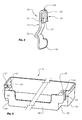
- Fig. 1
- shows a three-dimensional exploded view of a system for vertically adjusting a deposit container in a door of a household appliance;
- Fig. 2
- shows a three-dimensional view of a snap-action means of a system of
Fig. 1 ; - Fig. 3
- shows a three-dimensional view of a deposit container of a system of
Fig. 1 ; - Fig. 4
- shows a sectional view of a system of
Fig. 1 through a snap-action means in a vertical plane. - A system for vertically adjusting a deposit container in a door of a household appliance, particularly cooling and/or freezing apparatus is formed on the side of a
door 1 facing the interior of a household appliance not shown. Saiddoor 1 comprises at the side facing the interior of cooling and/or freezing apparatus aninner wall 2 which is formed in each verticalmarginal area 3, 4 thereof with a rail shapedprojection door 1. Each saidprojection opposite projection 5, 6 a fasteningrib deposit container 9. Said fasteningrib projection projection inner wall 2 and the free end of eachprojection rib projection rib end stop deposit container 9 to close to the lower edge of thedoor 1. It is provided for according to the present invention that each fasteningrib rib inner wall 2 of thedoor 1. Further, an embodiment is possible where said fastening means 12, 13 are formed on each fasteningrib fastening ribs rib inner wall 2 of saiddoor 1, preferably by means of a blow moulding. Additionally, each said fasteningrib deposit container 9 on thefastening ribs - Longitudinally, said
deposit container 9 is formed specular symmetrically with respect to the vertical, and accommodated on saiddoor 1 in a longitudinal area between said rail-shaped projections ribs transversal confine container 9 is formed over the entire height thereof and in the area of the association with aback wall 16, i.e. in the area located close to saidwall 2 of thedoor 1, with avertical groove rib groove container 9 up to said backwall 16, thus, creating astep back wall 16 and each saidtransversal confine groove transversal confine shaped receptacle transversal confine hole receptacle fastening rib deposit container 9 is provided with only one snap-action means. Preferably, said snap-action means 25, 26 are of identical shape, an embodiment is possible, though, with said snap-action means 25, 26 shaped differently with regard to the position thereof in thedeposit container 9, where in such a case the second snap-action means is shaped specular symmetrically with respect to the first snap-action means in a manner as described above for saiddeposit container 9. Therefore, only the first snap-action means 25 is described in the foregoing. - Said first snap-action means 25 is formed as a two-legged fastener with a first
flat leg 27 thereof being longer than a secondflat leg 28. The transversal dimension of said two-legged fastener is such that said fastener cooperates by means of a loose fit with saidreceptacle deposit container 9. Essentially, saidflat legs web 29 which enables a flexible movement of thelegs second leg 28 is formed from the free end thereof up to the area of saidweb 29 with a longitudinally extendingcut 30 which allows the portions of thesecond leg 28 created by said cut to be moved back and forth relative to each other. Further, saidsecond leg 28 is formed in the area of the free end thereof and at least at one side of said free end with a transversally extendingprojection 31 intended to cooperate with the through-hole container 9. The free end of saidprojection 31 is preferably formed with a slanted surface 31' the inclination thereof decreases in the direction from said free end of thesecond leg 28 towards saidweb 29. Saidfirst leg 27 is formed at the free end thereof with atransversal enlargement 32 intended to facilitate the cooperation with a user. Said first leg is formed in the area between saidweb 29 and saidtransversal enlargement 32 with aconvexity 33 which is intended to engage the trough of the rack formed fastening means 12, 13 when the snap-action means 25 is installed. Saidconvexity 33 resembles an approximate V shape and extends approximately in the direction perpendicular to the surface-wide portion of said flatfirst leg 27. According to the present invention it is provided for that both theconvexity 33 of each snap-action means 25, 26 and the corresponding troughs of each fastening means 12, 13 are formed with an undercut, thus, enabling a safe accommodation of thedeposit container 9 on said fastening means 12, 13. - Said
deposit container 9 is placed on to the inner side of saiddoor 1 of a cooling and/or freezing apparatus in the following way. Said snap-action means 25, 26 is inserted into at least one saidreceptacle deposit container 9, preferably into bothreceptacles projection 31 is bigger that the inner dimension of thereceptacle projection 31 over the inner wall of saidreceptacle second leg 28 of each snap-action means 25, 26 to be elastically deformed in the transversal direction of thesecond leg 28 due to said cut 30. When the snap-action means 25, 26 reaches the final position thereof, saidtransversal projection 31 snaps into said through-hole receptacle door 1 in a manner that eachvertical groove container 9 locks by means of the loose fit to the corresponding fastening rib, whereas saidconvexity 33 of the snap-action means 25, 26 engages the trough of the rack formed fastening means 12, 13. When thedeposit container 9 is to be adjusted on thedoor 1 vertically downwards, saidconvexity 33 disengages said trough of the rack formed fastening means 12, 13 by means of pushing eachtransversal enlargement 32 of eachfirst leg 27 of the two-legged fastener in the direction away from said wall of thedoor 1. Thus, thedeposit container 9 is released and ready to be vertically adjusted in thedoor 1. In order to adjust adeposit container 9 vertically upwards in thedoor 1 only a push upwards of thecontainer 9 is sufficient and saidconvexity 33 in a manner of a ratchet slides up and over each peak/trough of the rack formed fastening means 12, 13.
Claims (13)
- System for vertically adjusting a deposit container in a door (1) of a household appliance, particularly cooling and/or freezing apparatus, comprising a body with a compartment for accepting goods to be cooled, a door (1) for opening and closing said compartment with at least one deposit container (9), said door (1) comprising on the inner wall thereof at least one fastening rib (7, 8) for fixing said deposit container (9), characterized in that each fastening rib (7, 8) which is arranged on a rail shaped projection (5, 6) formed in each vertical marginal area (3, 4) on an inner wall (2) of said door (1) cooperates with a deposit container (9) and at least one snap-action means (25, 26) inserted into a corresponding receptacle (21, 22) of said container (9).
- System according to claim 1, characterized in that each transversal confine (14, 15) of said container (9) is formed over the entire height thereof and in the area of the association with a back wall (16) with a vertical groove (17, 18) being fitted to accept and to cooperate by means of a loose fit with each fastening rib (7, 8), each groove (17, 18) being provided in the transitional area to said transversal confine (14, 15) with a hollow box-shaped receptacle (21, 22), each one thereof being formed at the side of each transversal confine (14, 15) with a through-hole (23, 24).
- System according to claims 1 and 2, characterized in that said snap-action means (25, 26) is formed as a two-legged fastener with a first flat leg (27) thereof being longer than a second flat leg (28), said flat legs (27, 28) extending essentially in parallel and being associated by means of a web (29) which enables a flexible movement of the legs (27, 28) against each other.
- System according to claims 1 to 3, characterized in that said second leg (28) is formed from the free end thereof up to the area of said web (29) with a longitudinally extending cut (30) which allows the portions of the second leg (28) created by said cut to be moved back and forth relative to each other.
- System according to claims 1 to 3, characterized in that said second leg (28) is formed in the area of the free end thereof and at least at one side of said free end with a transversally extending projection (31) intended to cooperate with said through-hole (23, 24) of said container (9), the free end of said projection (31) being preferably formed with a slanted surface (31').
- System according to claim 5, characterized in that the inclination of said slanted surface (31') decreases in the direction from said free end of the second leg (28) towards said web (29).
- System according to claims 1 to 3, characterized in that said first leg (27) is formed at the free end thereof with a transversal enlargement (32) intended to facilitate the cooperation with a user, and said first leg (27) is formed in the area between said web (29) and said transversal enlargement (32) with a convexity (33) which is intended to engage the trough of a rack formed fastening means (12, 13) when the snap-action means (25, 26) is installed.
- System according to claim 7, characterized in that said convexity (33) which resembles an approximate V shape extends approximately in the direction perpendicular to the surface-wide portion of said flat first leg (27).
- System according to any of the preceding claims, characterized in that the fastening rib (7, 8) is arranged on each rail shaped projection (5, 6) spaced from said inner wall (2), preferably in the central area between the association of each projection (5, 6) with the inner wall (2) and the free end of each projection (5, 6).
- System according to any of the preceding claims, characterized in that said two-legged fastener is formed in a manner to cooperate by means of a loose fit with said receptacle (21, 22) of the deposit container (9).
- System according to any of the preceding claims, characterized in that said deposit container (9) is formed specular symmetrically with respect to the vertical.
- System according to any of the preceding claims, characterized in that the second snap-action means is formed specular symmetrically to the first snap-action means in a similar manner as said deposit container (9).
- System according to any of the preceding claims, characterized in that both the convexity (33) of each snap-action means (25, 26) and the corresponding troughs of each fastening means (12, 13) are formed with an undercut.
Applications Claiming Priority (1)
| Application Number | Priority Date | Filing Date | Title |
|---|---|---|---|
| SI201200147A SI24064A (en) | 2012-05-15 | 2012-05-15 | A system for displace of containers for disposal according to height door for household appliance |
Publications (2)
| Publication Number | Publication Date |
|---|---|
| EP2664878A2 true EP2664878A2 (en) | 2013-11-20 |
| EP2664878A3 EP2664878A3 (en) | 2015-01-28 |
Family
ID=48446099
Family Applications (1)
| Application Number | Title | Priority Date | Filing Date |
|---|---|---|---|
| EP13167399.8A Withdrawn EP2664878A3 (en) | 2012-05-15 | 2013-05-13 | System for vertically adjusting a deposit container in a door of a household appliance |
Country Status (2)
| Country | Link |
|---|---|
| EP (1) | EP2664878A3 (en) |
| SI (1) | SI24064A (en) |
Cited By (9)
| Publication number | Priority date | Publication date | Assignee | Title |
|---|---|---|---|---|
| EP2843333A1 (en) * | 2014-07-23 | 2015-03-04 | Gorenje d.d. | Enhanced system for vertically adjusting a deposit container in a door of a household appliance |
| DE102015118946A1 (en) | 2014-11-14 | 2016-05-19 | Gorenje Gospodinjski Aparati, D.D. | Household appliance with storage container |
| EP3032198A1 (en) * | 2014-12-08 | 2016-06-15 | BSH Hausgeräte GmbH | Door with a height adjustment device for a door stop, household cooler with such a door and method for adjusting a door stop |
| EP3064875A1 (en) | 2015-03-06 | 2016-09-07 | Gorenje Gospodinjski aparati d.d. | Household apparatus having a deposit container adjustable in the height of a door |
| US20170108265A1 (en) * | 2014-05-14 | 2017-04-20 | Hisense Ronshen (Guangdong) Refrigerator Co., Ltd. | Refrigerator |
| EP3217129A1 (en) * | 2016-03-09 | 2017-09-13 | Liebherr-Hausgeräte Ochsenhausen GmbH | Refrigeration and/or freezer device |
| EP3318828A1 (en) * | 2016-11-04 | 2018-05-09 | Samsung Electronics Co., Ltd. | Refrigerator |
| DE112014001857B4 (en) | 2014-05-14 | 2019-07-11 | Hisense Ronshen (Guangdong) Refrigerator Co., Ltd | fridge |
| EP3104106B1 (en) * | 2015-06-08 | 2023-04-19 | BSH Hausgeräte GmbH | Refrigeration device |
Citations (1)
| Publication number | Priority date | Publication date | Assignee | Title |
|---|---|---|---|---|
| EP2108907A1 (en) | 2008-04-09 | 2009-10-14 | BSH Bosch und Siemens Hausgeräte GmbH | Cooler, in particular household cooler, with multi-component door guide rail for a door shelf |
Family Cites Families (4)
| Publication number | Priority date | Publication date | Assignee | Title |
|---|---|---|---|---|
| FR1567154A (en) * | 1968-01-08 | 1969-05-16 | ||
| DE102009046614A1 (en) * | 2009-11-11 | 2011-05-12 | BSH Bosch und Siemens Hausgeräte GmbH | Refrigerating appliance with a door compartment and a visually exposed locking device |
| DE102010022203A1 (en) * | 2010-01-28 | 2011-08-18 | Liebherr-Hausgeräte Ochsenhausen GmbH, 88416 | Door of a refrigerator and / or freezer |
| EP2498031A1 (en) * | 2011-03-08 | 2012-09-12 | Electrolux Home Products Corporation N.V. | Refrigerating appliance |
-
2012
- 2012-05-15 SI SI201200147A patent/SI24064A/en not_active IP Right Cessation
-
2013
- 2013-05-13 EP EP13167399.8A patent/EP2664878A3/en not_active Withdrawn
Patent Citations (1)
| Publication number | Priority date | Publication date | Assignee | Title |
|---|---|---|---|---|
| EP2108907A1 (en) | 2008-04-09 | 2009-10-14 | BSH Bosch und Siemens Hausgeräte GmbH | Cooler, in particular household cooler, with multi-component door guide rail for a door shelf |
Cited By (13)
| Publication number | Priority date | Publication date | Assignee | Title |
|---|---|---|---|---|
| DE112014001610B4 (en) | 2014-05-14 | 2019-02-07 | Hisense Ronshen (Guangdong) Refrigerator Co., Ltd | fridge |
| US20170108265A1 (en) * | 2014-05-14 | 2017-04-20 | Hisense Ronshen (Guangdong) Refrigerator Co., Ltd. | Refrigerator |
| DE112014001857B4 (en) | 2014-05-14 | 2019-07-11 | Hisense Ronshen (Guangdong) Refrigerator Co., Ltd | fridge |
| US10317126B2 (en) * | 2014-05-14 | 2019-06-11 | Hisense Ronshen (Guangdong) Refrigerator Co., Ltd. | Refrigerator |
| EP2843333A1 (en) * | 2014-07-23 | 2015-03-04 | Gorenje d.d. | Enhanced system for vertically adjusting a deposit container in a door of a household appliance |
| DE102015118946A1 (en) | 2014-11-14 | 2016-05-19 | Gorenje Gospodinjski Aparati, D.D. | Household appliance with storage container |
| EP3032198A1 (en) * | 2014-12-08 | 2016-06-15 | BSH Hausgeräte GmbH | Door with a height adjustment device for a door stop, household cooler with such a door and method for adjusting a door stop |
| EP3064875A1 (en) | 2015-03-06 | 2016-09-07 | Gorenje Gospodinjski aparati d.d. | Household apparatus having a deposit container adjustable in the height of a door |
| EP3104106B1 (en) * | 2015-06-08 | 2023-04-19 | BSH Hausgeräte GmbH | Refrigeration device |
| EP3217129A1 (en) * | 2016-03-09 | 2017-09-13 | Liebherr-Hausgeräte Ochsenhausen GmbH | Refrigeration and/or freezer device |
| KR20180049931A (en) * | 2016-11-04 | 2018-05-14 | 삼성전자주식회사 | Refrigerator |
| CN108019996A (en) * | 2016-11-04 | 2018-05-11 | 三星电子株式会社 | Refrigerator |
| EP3318828A1 (en) * | 2016-11-04 | 2018-05-09 | Samsung Electronics Co., Ltd. | Refrigerator |
Also Published As
| Publication number | Publication date |
|---|---|
| EP2664878A3 (en) | 2015-01-28 |
| SI24064A (en) | 2013-11-29 |
Similar Documents
| Publication | Publication Date | Title |
|---|---|---|
| EP2664878A2 (en) | System for vertically adjusting a deposit container in a door of a household appliance | |
| EP2843333A1 (en) | Enhanced system for vertically adjusting a deposit container in a door of a household appliance | |
| US7669945B2 (en) | Refrigerating or freezing apparatus | |
| EP3011241B1 (en) | Continuously adjustable door bins | |
| US20160325885A1 (en) | Container for transporting goods and device for dividing such a container | |
| KR102292852B1 (en) | Shaving assembly dispenser | |
| US20110115356A1 (en) | Shelf for an appliance | |
| US10531719B2 (en) | Shaving assembly dispenser | |
| US10451338B2 (en) | Door storage bin assembly for a refrigerator | |
| US10349719B2 (en) | Shaving razor tray | |
| CN109210860B (en) | Storage mechanism | |
| US8261920B1 (en) | Portable shelf unit supported by a towel bar | |
| US8853575B2 (en) | Switching apparatus | |
| RU2552062C1 (en) | Container for cooled products and refrigerator with such container | |
| EP3064875A1 (en) | Household apparatus having a deposit container adjustable in the height of a door | |
| EP2833090B1 (en) | Refrigerator with drawer | |
| CN109489320B (en) | Domestic refrigerator with a special front depression of a shelf | |
| EP3173717B1 (en) | Household refrigerating device with a transport securing element | |
| JP5391044B2 (en) | Storage container set and drawer with storage container provided with the same | |
| CN108534446B (en) | Container for cooling material | |
| JP2009160119A (en) | Food service cart | |
| KR20070102188A (en) | Door shelf of refrigerator | |
| CN214665525U (en) | Storage base for a domestic refrigeration device | |
| JP5919136B2 (en) | Sink drainer rack | |
| JP5043967B2 (en) | Lids and containers |
Legal Events
| Date | Code | Title | Description |
|---|---|---|---|
| PUAI | Public reference made under article 153(3) epc to a published international application that has entered the european phase |
Free format text: ORIGINAL CODE: 0009012 |
|
| AK | Designated contracting states |
Kind code of ref document: A2 Designated state(s): AL AT BE BG CH CY CZ DE DK EE ES FI FR GB GR HR HU IE IS IT LI LT LU LV MC MK MT NL NO PL PT RO RS SE SI SK SM TR |
|
| AX | Request for extension of the european patent |
Extension state: BA ME |
|
| PUAL | Search report despatched |
Free format text: ORIGINAL CODE: 0009013 |
|
| AK | Designated contracting states |
Kind code of ref document: A3 Designated state(s): AL AT BE BG CH CY CZ DE DK EE ES FI FR GB GR HR HU IE IS IT LI LT LU LV MC MK MT NL NO PL PT RO RS SE SI SK SM TR |
|
| AX | Request for extension of the european patent |
Extension state: BA ME |
|
| RIC1 | Information provided on ipc code assigned before grant |
Ipc: A47B 57/34 20060101ALI20141222BHEP Ipc: F25D 23/04 20060101AFI20141222BHEP |
|
| STAA | Information on the status of an ep patent application or granted ep patent |
Free format text: STATUS: THE APPLICATION IS DEEMED TO BE WITHDRAWN |
|
| 18D | Application deemed to be withdrawn |
Effective date: 20150729 |