EP2664785A2 - Vehicle starter and transmission mechanism for the same - Google Patents
Vehicle starter and transmission mechanism for the same Download PDFInfo
- Publication number
- EP2664785A2 EP2664785A2 EP13168353.4A EP13168353A EP2664785A2 EP 2664785 A2 EP2664785 A2 EP 2664785A2 EP 13168353 A EP13168353 A EP 13168353A EP 2664785 A2 EP2664785 A2 EP 2664785A2
- Authority
- EP
- European Patent Office
- Prior art keywords
- overrunning clutch
- transmission mechanism
- output shaft
- transmission
- inner sleeve
- Prior art date
- Legal status (The legal status is an assumption and is not a legal conclusion. Google has not performed a legal analysis and makes no representation as to the accuracy of the status listed.)
- Granted
Links
- 230000005540 biological transmission Effects 0.000 title claims abstract description 63
- 239000007858 starting material Substances 0.000 title claims abstract description 30
- 239000003638 chemical reducing agent Substances 0.000 claims abstract description 26
- 238000004519 manufacturing process Methods 0.000 description 4
- 230000000694 effects Effects 0.000 description 3
- 230000013011 mating Effects 0.000 description 3
- 238000000034 method Methods 0.000 description 2
- 238000002485 combustion reaction Methods 0.000 description 1
- 238000013016 damping Methods 0.000 description 1
- 238000003754 machining Methods 0.000 description 1
- 238000012986 modification Methods 0.000 description 1
- 230000004048 modification Effects 0.000 description 1
- 230000002035 prolonged effect Effects 0.000 description 1
Images

Classifications
-
- F—MECHANICAL ENGINEERING; LIGHTING; HEATING; WEAPONS; BLASTING
- F02—COMBUSTION ENGINES; HOT-GAS OR COMBUSTION-PRODUCT ENGINE PLANTS
- F02N—STARTING OF COMBUSTION ENGINES; STARTING AIDS FOR SUCH ENGINES, NOT OTHERWISE PROVIDED FOR
- F02N15/00—Other power-operated starting apparatus; Component parts, details, or accessories, not provided for in, or of interest apart from groups F02N5/00 - F02N13/00
- F02N15/02—Gearing between starting-engines and started engines; Engagement or disengagement thereof
- F02N15/022—Gearing between starting-engines and started engines; Engagement or disengagement thereof the starter comprising an intermediate clutch
- F02N15/023—Gearing between starting-engines and started engines; Engagement or disengagement thereof the starter comprising an intermediate clutch of the overrunning type
-
- F—MECHANICAL ENGINEERING; LIGHTING; HEATING; WEAPONS; BLASTING
- F02—COMBUSTION ENGINES; HOT-GAS OR COMBUSTION-PRODUCT ENGINE PLANTS
- F02N—STARTING OF COMBUSTION ENGINES; STARTING AIDS FOR SUCH ENGINES, NOT OTHERWISE PROVIDED FOR
- F02N15/00—Other power-operated starting apparatus; Component parts, details, or accessories, not provided for in, or of interest apart from groups F02N5/00 - F02N13/00
- F02N15/02—Gearing between starting-engines and started engines; Engagement or disengagement thereof
- F02N15/04—Gearing between starting-engines and started engines; Engagement or disengagement thereof the gearing including disengaging toothed gears
- F02N15/043—Gearing between starting-engines and started engines; Engagement or disengagement thereof the gearing including disengaging toothed gears the gearing including a speed reducer
-
- F—MECHANICAL ENGINEERING; LIGHTING; HEATING; WEAPONS; BLASTING
- F02—COMBUSTION ENGINES; HOT-GAS OR COMBUSTION-PRODUCT ENGINE PLANTS
- F02N—STARTING OF COMBUSTION ENGINES; STARTING AIDS FOR SUCH ENGINES, NOT OTHERWISE PROVIDED FOR
- F02N11/00—Starting of engines by means of electric motors
-
- F—MECHANICAL ENGINEERING; LIGHTING; HEATING; WEAPONS; BLASTING
- F02—COMBUSTION ENGINES; HOT-GAS OR COMBUSTION-PRODUCT ENGINE PLANTS
- F02N—STARTING OF COMBUSTION ENGINES; STARTING AIDS FOR SUCH ENGINES, NOT OTHERWISE PROVIDED FOR
- F02N15/00—Other power-operated starting apparatus; Component parts, details, or accessories, not provided for in, or of interest apart from groups F02N5/00 - F02N13/00
- F02N15/02—Gearing between starting-engines and started engines; Engagement or disengagement thereof
- F02N15/022—Gearing between starting-engines and started engines; Engagement or disengagement thereof the starter comprising an intermediate clutch
- F02N15/025—Gearing between starting-engines and started engines; Engagement or disengagement thereof the starter comprising an intermediate clutch of the friction type
-
- F—MECHANICAL ENGINEERING; LIGHTING; HEATING; WEAPONS; BLASTING
- F02—COMBUSTION ENGINES; HOT-GAS OR COMBUSTION-PRODUCT ENGINE PLANTS
- F02N—STARTING OF COMBUSTION ENGINES; STARTING AIDS FOR SUCH ENGINES, NOT OTHERWISE PROVIDED FOR
- F02N15/00—Other power-operated starting apparatus; Component parts, details, or accessories, not provided for in, or of interest apart from groups F02N5/00 - F02N13/00
- F02N15/02—Gearing between starting-engines and started engines; Engagement or disengagement thereof
- F02N15/022—Gearing between starting-engines and started engines; Engagement or disengagement thereof the starter comprising an intermediate clutch
- F02N15/026—Gearing between starting-engines and started engines; Engagement or disengagement thereof the starter comprising an intermediate clutch of the centrifugal type
-
- F—MECHANICAL ENGINEERING; LIGHTING; HEATING; WEAPONS; BLASTING
- F02—COMBUSTION ENGINES; HOT-GAS OR COMBUSTION-PRODUCT ENGINE PLANTS
- F02N—STARTING OF COMBUSTION ENGINES; STARTING AIDS FOR SUCH ENGINES, NOT OTHERWISE PROVIDED FOR
- F02N15/00—Other power-operated starting apparatus; Component parts, details, or accessories, not provided for in, or of interest apart from groups F02N5/00 - F02N13/00
- F02N15/02—Gearing between starting-engines and started engines; Engagement or disengagement thereof
- F02N15/04—Gearing between starting-engines and started engines; Engagement or disengagement thereof the gearing including disengaging toothed gears
- F02N15/043—Gearing between starting-engines and started engines; Engagement or disengagement thereof the gearing including disengaging toothed gears the gearing including a speed reducer
- F02N15/046—Gearing between starting-engines and started engines; Engagement or disengagement thereof the gearing including disengaging toothed gears the gearing including a speed reducer of the planetary type
-
- F—MECHANICAL ENGINEERING; LIGHTING; HEATING; WEAPONS; BLASTING
- F02—COMBUSTION ENGINES; HOT-GAS OR COMBUSTION-PRODUCT ENGINE PLANTS
- F02N—STARTING OF COMBUSTION ENGINES; STARTING AIDS FOR SUCH ENGINES, NOT OTHERWISE PROVIDED FOR
- F02N15/00—Other power-operated starting apparatus; Component parts, details, or accessories, not provided for in, or of interest apart from groups F02N5/00 - F02N13/00
- F02N15/02—Gearing between starting-engines and started engines; Engagement or disengagement thereof
- F02N15/04—Gearing between starting-engines and started engines; Engagement or disengagement thereof the gearing including disengaging toothed gears
- F02N15/06—Gearing between starting-engines and started engines; Engagement or disengagement thereof the gearing including disengaging toothed gears the toothed gears being moved by axial displacement
- F02N15/062—Starter drives
- F02N15/063—Starter drives with resilient shock absorbers
-
- F—MECHANICAL ENGINEERING; LIGHTING; HEATING; WEAPONS; BLASTING
- F02—COMBUSTION ENGINES; HOT-GAS OR COMBUSTION-PRODUCT ENGINE PLANTS
- F02N—STARTING OF COMBUSTION ENGINES; STARTING AIDS FOR SUCH ENGINES, NOT OTHERWISE PROVIDED FOR
- F02N15/00—Other power-operated starting apparatus; Component parts, details, or accessories, not provided for in, or of interest apart from groups F02N5/00 - F02N13/00
- F02N15/02—Gearing between starting-engines and started engines; Engagement or disengagement thereof
- F02N15/04—Gearing between starting-engines and started engines; Engagement or disengagement thereof the gearing including disengaging toothed gears
- F02N15/06—Gearing between starting-engines and started engines; Engagement or disengagement thereof the gearing including disengaging toothed gears the toothed gears being moved by axial displacement
- F02N15/067—Gearing between starting-engines and started engines; Engagement or disengagement thereof the gearing including disengaging toothed gears the toothed gears being moved by axial displacement the starter comprising an electro-magnetically actuated lever
Definitions
- the present invention relates to a transmission mechanism for a vehicle starter and a vehicle starter having the transmission mechanism.
- an electric starter is usually used to start an internal combustion engine of the vehicle.
- the starter is used to convert electrical energy stored in a rechargeable battery into mechanical energy which causes the engine of the vehicle to operate. In this way, the engine is started.
- the starter is generally comprised of a direct-current (DC) electric motor, a transmission mechanism and a controller.
- DC direct-current
- the electric motor is supplied with direct current from the battery to generate a torque.
- This torque is transmitted via the transmission mechanism to a ring gear on a flywheel of the engine such that a crankshaft of the engine is driven to rotate.
- the transmission mechanism comprises a speed reducer connected to an output shaft of the electric motor, an overrunning clutch connected to the speed reducer, an output shaft which is connected to the overrunning clutch at its inner end via a spline device, and a pinion which is mounted at an outer end of the output shaft of the transmission mechanism and is used to drive the ring gear.
- the spline device comprises an inner spline formed in the overrunning clutch and an outer spline formed at the inner end of the output shaft of the transmission mechanism for mating with the inner spline.
- the outer spline is movable axially relative to the inner spline.
- the controller is used to control operation of the electric motor and axial movement of the output shaft of the transmission mechanism so as to enable the pinion to engage with or disengage from the ring gear.
- FIGS 1a and 1b show a basic structure of the overrunning clutch of the transmission mechanism in a simple manner.
- the overrunning clutch generally comprises an outer sleeve 1, an inner sleeve 2 and rollers 3 disposed between the outer sleeve 1 and the inner sleeve 2.
- Involute structures 1.1 are provided on the outer sleeve 1 such that each roller 3, which is loaded by a respective spring 4, always contacts with surfaces of the outer sleeve 1 (i.e. the respective involute structure 1.1 thereon) and the inner sleeve 2.
- the output shaft of the electric motor drives the inner sleeve 2 to rotate, for example, in a clockwise direction such that each roller 3 tends to move towards a direction in which a gap between the involute structure 1.1 and the surface of the inner sleeve 2 is narrowed. Therefore, as a result of geometry of the involute structure 1.1, each roller 3 is compressed and clamped between the outer sleeve 1 and the inner sleeve 2. In this way, in terms of rotation transferring, the outer sleeve 1 is rigidly coupled to the inner sleeve 2 in the clockwise direction. That is, no relative movement can occur between the two sleeves in the clockwise direction. Therefore, the outer sleeve 1 of the overrunning clutch is driven to rotate in the clockwise direction.
- Figure 1a shows how the overrunning clutch transmits the rotation in an ideal case.
- the outer sleeve 1 of the overrunning clutch is possibly not coaxial with the inner sleeve 2.
- the overrunning clutch after being assembled will become an integrated member having input and output shafts which are not coaxial with each other.
- FIG 1b shows how the overrunning clutch transmits the rotation in an ideal case.
- the outer sleeve 1 is influenced by radial vibrations, each roller 3 will be moved differently towards the direction in which the gap between the involute structure 1.1 and the surface of the inner sleeve 2 is narrowed.
- the driving assembly comprises a pinion, a spring, first and second snap rings, a damping element, a sleeve and bearings, wherein protrusions integrally formed on the sleeve are disposed in slots of the pinion such that it is driven to rotate.
- This kind of configuration is disadvantageous in that, if self-vibrations or force occur(s) as mentioned above; it is still hard to solve the problem that there is a poor coaxiality between the sleeve and the pinion.
- a transmission mechanism for a vehicle starter which comprises: a speed reducer connected to an output shaft of an electric motor of the vehicle starter ; an overrunning clutch connected to the speed reducer, the overrunning clutch having a driving part, a driven part and a movement transmitting element provided between the driving and driven parts for achieving transmission of a one-way movement therebetween; and an output shaft connected to the overrunning clutch, wherein the transmission mechanism further comprises a transmission carrier, the overrunning clutch is connected to the speed reducer via the transmission carrier in such a way that rotational movement (that is, torque) is able to transmit only from the speed reducer to the overrunning clutch, the driving part of the overrunning clutch is mounted in the transmission carrier with play, and the transmission carrier is mounted on the output shaft of the electric motor.
- the play has a value between 0.2 millimeter and 0.8 millimeter, preferably of 0.5 millimeter.
- the driving part of the overrunning clutch has a projection
- the transmission carrier has a receiving slot
- the projection is mounted in the receiving slot with play.
- the driving part of the overrunning clutch has a receiving slot
- the transmission carrier has a projection
- the projection is mounted in the receiving slot with play.
- a rubber piece is provided between the projection and the receiving slot.
- the rubber piece is provided with a hollow structure for absorbing vibration.
- the driving part of the overrunning clutch is an inner sleeve thereof
- the driven part of the overrunning clutch is an outer sleeve thereof.
- the driving part of the overrunning clutch is an outer sleeve thereof
- the driven part of the overrunning clutch is an inner sleeve thereof.
- the transmission carrier is mounted on the output shaft of the electric motor by a bearing.
- a vehicle starter comprising said transmission mechanism is provided.
- manufacturing difficulty and costs are both reduced because the driving part of the overrunning clutch requiring high rigidity is manufactured independently of the transmission carrier not requiring high rigidity. Further, because the driving part is connected to the transmission carrier with play so as to be driven to rotate, any non-coaxial effect between the driving and driven parts of the overrunning clutch caused by radial vibrations or impacts can be compensated. Improved efficiency and a prolonged servicing life of the vehicle starter can be obtained.
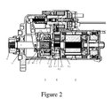
- FIG. 2 shows a part of a vehicle starter according to a preferred embodiment of the present invention.
- the starter mainly comprises a DC electric motor 5, a transmission mechanism and a controller.
- the electric motor 5 is installed in a housing of the starter. When an engine of the vehicle is started, the electric motor 5 is supplied with direct current from a rechargeable battery under controlling of the controller such that the electric motor 5 is operated to generate a torque. This torque is transmitted via the transmission mechanism to a ring gear on a flywheel of the engine in such a way that a crankshaft of the engine is driven to rotate.
- the transmission mechanism mainly comprises a speed reducer 8 connected to an output shaft 5.1 of the electric motor 5, an overrunning clutch 9 connected to the speed reducer 8, an output shaft 7 whose inner end (adjacent the electric motor 5) is connected to the overrunning clutch 9 via a spline device 10, and a pinion 6 which is mounted at an outer end (far away from the electric motor 5) of the output shaft 7 and is used to drive the ring gear.
- the speed reducer 8 can be a speed reducer of any form, for example, a gear speed reducer.
- a planetary gear speed reducer is illustrated in figure 2 .
- the planetary gear speed reducer comprises a sun gear 8.1 mounted on the output shaft of the electric motor 5, an outer ring gear 8.2 mounted around the sun gear 8.1 fixedly and coaxially, and at least a planet gear 8.3 engaged between the sun gear and the outer ring gear.
- a central shaft 8.4 of the planet gear 8.3 is mounted on for example a planet carrier 12.
- the overrunning clutch 9 comprises an outer sleeve 1, an inner sleeve 2 and a movement transmitting element 3, for example a roller between the outer and inner sleeves for transmitting a one-way movement therebetween.
- a plurality of involute structures 1.1 can be provided in the outer sleeve 1.
- the involute structure can be in the form of an involute canal.
- One roller 3 and one spring 4 are allocated for each involute structure 1.1 such that one end of the spring 4 is fixed and the other end thereof pushes against the roller 3. Therefore, in each case, the roller 3 always contacts with both the outer sleeve 1 (that is, the involute structure thereon) and the inner sleeve 2.
- each roller 3 tends to move towards a direction in which the gap between the involute structure 1.1 and the inner sleeve is narrowed such that both the inner sleeve and the outer sleeve apply a pressure on the roller 3.
- the output shaft 7, that is the outer sleeve 1 of the overrunning clutch 9 will be rotated at a speed higher than the inner sleeve 2. At this time, the rigid connection mentioned above will be lost between the outer sleeve 1 and the inner sleeve 2.
- the movement transmitting element 3 of the overrunning clutch is the roller.
- the movement transmitting element 3 can be embodied as any other suitable form which is well-known in the art, for example a wedge, a ratchet or the like.
- the inner sleeve 2 is constituted as a driving part of the overrunning clutch 9 and the outer sleeve 1 is constituted as a driven part of the overrunning clutch 9.
- the outer sleeve 1 is constituted as the driving part and the inner sleeve 2 is constituted as the driven part.
- the driven part of the overrunning clutch 9 transmits the rotational movement from the speed reducer 8 to the output shaft 7 via the spline device 10.
- the spline device 10 comprises an inner spline part and an outer spline part mating therewith.
- the inner spline part is formed or mounted on the driven part (the outer sleeve 1 illustrated in figure 2 ) of the overrunning clutch 9.
- the outer spline part is formed or mounted at the inner end of the output shaft 7.
- the output shaft 7 is supported by bearings 11 and 13 in the housing of the starter.
- the pinion 6 is mounted on the outer end of the output shaft 7. By axial movement of the output shaft 7, the pinion 6 can be engaged with or disengaged from the ring gear (not shown) on the flywheel of the engine.
- the pinion 6 When the pinion 6 is engaged with the ring gear, the rotational movement and the torque generated by the electric motor 5 are transmitted to the ring gear successively via the speed reducer 8, the overrunning clutch 9, the spline device 10, the output shaft 7 and the pinion 6 such that the flywheel of the engine is driven to rotate and thus the engine can be started.
- the inner sleeve is usually integrated with the planet carrier. That is, a corresponding through hole is processed, for example machined, in the planet carrier, in which the central shaft of the planet gear is inserted so as to connect it to the planet carrier. In this way, the rotational movement is transmitted.
- this technical solution is disadvantageous in that the inner sleeve must be processed with hardness greatly higher than the planet carrier. Therefore, different heat processes are necessary for the same component, which leads to manufacturing difficulty thereof.
- the inner sleeve 2 of the overrunning clutch is manufactured independently of the planet carrier 12. Then, they are assembled together. In this way, the heat process is necessary only for the inner sleeve of the overrunning clutch to increase its hardness, which obviously leads to simple manufacturing thereof.
- the planet carrier 12 is machined with a through hole at its center.
- the free end (i.e. the end adjacent the pinion 6) of the output shaft 5.1 of the electric motor 5 is mounted in the central hole of the planet carrier 12 via a slide bearing 14. Therefore, because the free end of the output shaft 5.1 of the electric motor 5 is mounted in the central hole of the planet carrier 12 via the slide bearing 14, the coaxiality of the planet carrier itself relative to the output shaft of the electric motor is ensured.
- a receiving slot is machined in the planet carrier to receive a protrusion protruding from the inner sleeve of the overrunning clutch such that the rotational movement is transmitted.
- slide bearing 14 is illustrated in figure 2 , it is conceived that any other suitable bearing which achieves the same function, such as a needle bearing, a roller bearing or the like, can be adopted by the present invention.
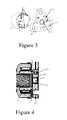
- FIG. 3 shows the inner sleeve of the overrunning clutch and the planet carrier according to a preferred embodiment of the present invention in an exploded and perspective view.
- the inner sleeve 2 is substantially in the shape of a hollow cylinder.
- a circumferential flange 2.1 is formed on one side of the inner sleeve 2 adjacent the output shaft of the electric motor.
- a plurality of arc-shaped projections 2.2 are formed on the circumferential flange 2.1. In the illustrated embodiment, three arc-shaped projections 2.2 are shown for example.
- the planet carrier 12 is shown as a rounded triangle shape. However, the planet carrier is not limited by this.
- the planet carrier 12 can be circular, annular or the like.
- a central hole 12.1 is machined at the center of the planet carrier 12 such that the output shaft of the electric motor is mounted in the central hole by the bearing 14. Additionally, three through holes 12.2 are machined in the planet carrier 12 to receive respective central shafts of planet gears of the planetary gear speed reducer. According to the preferred embodiment of the present invention, it is important that a plurality of arc-shaped receiving slots 12.3, for example three arc-shaped receiving slots are machined in the planet carrier 12 for mating with the projections 2.2 of the inner sleeve 2.
- Figure 4 shows a cross-sectional view of the inner sleeve 2 assembled together with the planet carrier 12. Specifically, this figure shows an enlarged view of the dashed box illustrated in figure 2 . As shown in figure 4 , the central hole 12.1 of the planet carrier 12 receives the free end of the output shaft 5.1 by the bearing 14 in such a way that the coaxiality of the planet carrier 12 relative to the output shaft is ensured.
- each arc-shaped receiving slot 12.3 is machined with a size larger than the respective projection 2.2 or alternatively each projection 2.2 is machined with a size less than the respective arc-shaped receiving slot 12.3 such that each projection 2.2 is mounted in the arc-shaped receiving slot 12.3 with play.
- connection with play means that the size of the arc-shaped receiving slot is larger than that of the projection of the inner sleeve in each direction or the size of the projection of the inner sleeve is less than that of the arc-shaped receiving slot in each direction. That is, when the projection of the inner sleeve is received in the arc-shaped receiving slot, a clearance or play exists therebetween in a radial or circumferential direction of the planet carrier.
- the technical problem that the coaxiality becomes poor can be perfectly solved if the clearance or play has a value of 0.5 millimeter.
- the clearance or play can be selected in a range between 0.2 millimeter and 0.8 millimeter.
- the free end of the output shaft 5.1 is mounted in the central hole 12.1 of the planet carrier 12 by the bearing 14 such that the coaxiality of the planet carrier 12 itself is ensured.
- the projection 2.2 of the inner sleeve 2 of the overrunning clutch is received in the receiving slot of the planet carrier 12 with play such that, when the rotational movement is transmitted, the projection can be moved somewhat in the receiving slot so as to counteract the negative effect caused by vibrations.
- the projection or the receiving slot is arc-shaped in the illustrated embodiment, it is conceived that they can be formed as other suitable shapes. For example, they can be circular, rectangular or the like as long as the projection or the receiving slot is sized as mentioned above in such a way that the projection can be received in the receiving slot with play.
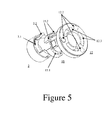
- FIG. 5 shows an exploded and perspective view of another preferred embodiment of the present invention.
- the inner sleeve 2 of the overrunning clutch, rubber pieces 15 and a planet carrier 12 are illustrated in an exploded manner.
- Each rubber piece 15 is shaped and sized to just receive the respective projection 2.2 of the inner sleeve 2 and at the same time to be received in a respective receiving slot 12.3 of the planet carrier 12.
- the inner sleeve of the overrunning clutch can also be considered to connect to the planet carrier with play. Except for this, the context about how the inner sleeve of the overrunning clutch and the planet carrier are arranged in the vehicle starter is the same as the embodiment of figure 2 and thus is omitted here.
- the planet carrier is for example in the shape of a circle.
- a central hole is also provided at the center of the planet carrier.
- the bearing 14 mentioned above can be mounted in the central hole such that the output shaft 5.1 of the electric motor 5 can be mounted in the central hole by the bearing, as shown in figure 2 . In this way, the coaxiality of the planet carrier 12 is ensured.
- each rubber piece 15 can be in the shape of an arc which corresponds with the projection 2.2 and the receiving slot 12.3.
- the arc-shaped rubber piece 15 is provided with an arc-shaped receiving slot 15.1 at its center to receive the projection 2.2 of the inner sleeve 2.
- a through hole 15.2 can be formed in the rubber piece at either side of the receiving slot 15.1.
- the overrunning clutch can be connected to the planet carrier 12 with play while any vibration is avoided.
- the rubber piece 15 can be formed correspondingly such that the rubber piece is adaptable to receive the projection of the inner sleeve of the overrunning clutch and at the same time to be received in the receiving slot of the planet carrier.
- any other suitable structure which achieves a connection with play between the inner sleeve and the planet carrier and transmits movement therebetween, can be adopted by the present invention.
- such structure can be a key-slot structure.
- the key-slot structure comprises a key and a slot which are provided to the inner sleeve and the planet carrier respectively and are sized to achieve the connection with play between the inner sleeve and the planet carrier.
- the rubber piece can be provided as a block between the key and the slot.
- the coaxiality of the planet carrier is ensured by the output shaft of the electric motor being mounted in the central hole of the planet carrier. It is feasible to ensure the coaxiality by other suitable solutions.
- a reference site can be machined in the housing of the starter in advance.
- the planet carrier is for example mounted at the reference site to ensure its coaxiality, and other components are assembled with respect to the reference site.
- the planet carrier can be provided with the receiving slot or the projection mentioned above to engage with the corresponding projection or receiving slot of the inner sleeve of the overrunning clutch such that the planet carrier is connected to the inner sleeve with play. Therefore, any poor coaxiality of the planet carrier relative to the inner sleeve caused by radial vibrations can be counteracted or compensated.
- the planetary gear speed reducer is used in the specific embodiments of the present invention to explain the overrunning clutch, it is conceived that any other speed reducer, for example a gearbox, can be used.
- the planet carrier can be replaced with a transmission carrier.
- This transmission carrier is embodied in a similar manner as the planet carrier.
- this transmission carrier will be mounted on an output shaft of the gearbox. In this way, the coaxiality of the transmission carrier relative to the inner sleeve of the overrunning clutch can be ensured.
- the transmission carrier is provided with the receiving slot or projection mentioned above to engage with a corresponding structure in the inner sleeve of the overrunning clutch, any vibration or deviation occurring during operation of the engine can be compensated.
- the transmission mechanism according to the present invention is adapted to starters of various vehicles, for example a starter for a diesel engine.
Abstract
Description
- The present invention relates to a transmission mechanism for a vehicle starter and a vehicle starter having the transmission mechanism.
- In a modem vehicle, an electric starter is usually used to start an internal combustion engine of the vehicle. The starter is used to convert electrical energy stored in a rechargeable battery into mechanical energy which causes the engine of the vehicle to operate. In this way, the engine is started.
- The starter is generally comprised of a direct-current (DC) electric motor, a transmission mechanism and a controller. When the engine of the vehicle is started, the electric motor is supplied with direct current from the battery to generate a torque. This torque is transmitted via the transmission mechanism to a ring gear on a flywheel of the engine such that a crankshaft of the engine is driven to rotate. The transmission mechanism comprises a speed reducer connected to an output shaft of the electric motor, an overrunning clutch connected to the speed reducer, an output shaft which is connected to the overrunning clutch at its inner end via a spline device, and a pinion which is mounted at an outer end of the output shaft of the transmission mechanism and is used to drive the ring gear. The spline device comprises an inner spline formed in the overrunning clutch and an outer spline formed at the inner end of the output shaft of the transmission mechanism for mating with the inner spline. The outer spline is movable axially relative to the inner spline. The controller is used to control operation of the electric motor and axial movement of the output shaft of the transmission mechanism so as to enable the pinion to engage with or disengage from the ring gear.
-
Figures 1a and 1b show a basic structure of the overrunning clutch of the transmission mechanism in a simple manner. The overrunning clutch generally comprises anouter sleeve 1, aninner sleeve 2 androllers 3 disposed between theouter sleeve 1 and theinner sleeve 2. Involute structures 1.1 are provided on theouter sleeve 1 such that eachroller 3, which is loaded by arespective spring 4, always contacts with surfaces of the outer sleeve 1 (i.e. the respective involute structure 1.1 thereon) and theinner sleeve 2. When the electric motor is activated, the output shaft of the electric motor drives theinner sleeve 2 to rotate, for example, in a clockwise direction such that eachroller 3 tends to move towards a direction in which a gap between the involute structure 1.1 and the surface of theinner sleeve 2 is narrowed. Therefore, as a result of geometry of the involute structure 1.1, eachroller 3 is compressed and clamped between theouter sleeve 1 and theinner sleeve 2. In this way, in terms of rotation transferring, theouter sleeve 1 is rigidly coupled to theinner sleeve 2 in the clockwise direction. That is, no relative movement can occur between the two sleeves in the clockwise direction. Therefore, theouter sleeve 1 of the overrunning clutch is driven to rotate in the clockwise direction. -
Figure 1a shows how the overrunning clutch transmits the rotation in an ideal case. However, due to self-vibration of the overrunning clutch or force applied thereto, theouter sleeve 1 of the overrunning clutch is possibly not coaxial with theinner sleeve 2. In a case that theouter sleeve 1 is not coaxial with theinner sleeve 2, the overrunning clutch after being assembled will become an integrated member having input and output shafts which are not coaxial with each other. This case is illustrated infigure 1b . For example, if theouter sleeve 1 is influenced by radial vibrations, eachroller 3 will be moved differently towards the direction in which the gap between the involute structure 1.1 and the surface of theinner sleeve 2 is narrowed. Therefore, a poor coaxiality between theouter sleeve 1 and theinner sleeve 2 is achieved. High-speed rotation of components which are not coaxial with each other can lead to a series of negative effects, such as a stronger impact on the component, lower efficiency of the starter and even a shorter service life of the starter. - Document
US 2011247437A discloses a driving assembly for a vehicle starter. The driving assembly comprises a pinion, a spring, first and second snap rings, a damping element, a sleeve and bearings, wherein protrusions integrally formed on the sleeve are disposed in slots of the pinion such that it is driven to rotate. This kind of configuration is disadvantageous in that, if self-vibrations or force occur(s) as mentioned above; it is still hard to solve the problem that there is a poor coaxiality between the sleeve and the pinion. - It is an object of the present invention to improve the transmission mechanism of the vehicle such that it can be manufactured simply and a perfect coaxiality is ensured.
- According to one aspect of the present invention, a transmission mechanism for a vehicle starter is provided, which comprises: a speed reducer connected to an output shaft of an electric motor of the vehicle starter ; an overrunning clutch connected to the speed reducer, the overrunning clutch having a driving part, a driven part and a movement transmitting element provided between the driving and driven parts for achieving transmission of a one-way movement therebetween; and an output shaft connected to the overrunning clutch, wherein the transmission mechanism further comprises a transmission carrier, the overrunning clutch is connected to the speed reducer via the transmission carrier in such a way that rotational movement (that is, torque) is able to transmit only from the speed reducer to the overrunning clutch, the driving part of the overrunning clutch is mounted in the transmission carrier with play, and the transmission carrier is mounted on the output shaft of the electric motor.
- Preferably, the play has a value between 0.2 millimeter and 0.8 millimeter, preferably of 0.5 millimeter.
- Optionally, the driving part of the overrunning clutch has a projection, the transmission carrier has a receiving slot, and the projection is mounted in the receiving slot with play.
- Optionally, the driving part of the overrunning clutch has a receiving slot, the transmission carrier has a projection, and the projection is mounted in the receiving slot with play.
- Preferably, a rubber piece is provided between the projection and the receiving slot.
- Preferably, the rubber piece is provided with a hollow structure for absorbing vibration.
- Optionally, the driving part of the overrunning clutch is an inner sleeve thereof, and the driven part of the overrunning clutch is an outer sleeve thereof.
- Optionally, the driving part of the overrunning clutch is an outer sleeve thereof, and the driven part of the overrunning clutch is an inner sleeve thereof.
- Preferably, the transmission carrier is mounted on the output shaft of the electric motor by a bearing.
- According to another aspect of the present invention, a vehicle starter comprising said transmission mechanism is provided.
- According to technical solutions given by the description and claims, manufacturing difficulty and costs are both reduced because the driving part of the overrunning clutch requiring high rigidity is manufactured independently of the transmission carrier not requiring high rigidity. Further, because the driving part is connected to the transmission carrier with play so as to be driven to rotate, any non-coaxial effect between the driving and driven parts of the overrunning clutch caused by radial vibrations or impacts can be compensated. Improved efficiency and a prolonged servicing life of the vehicle starter can be obtained.
-
-
Figure 1a schematically shows an overrunning clutch of a vehicle starter in a normal condition; -
Figure 1b schematically shows the overrunning clutch of the vehicle starter in a case that a poor coaxiality occurs in the overrunning clutch. -
Figure 2 schematically shows a cross-sectional view of a vehicle starter and its transmission mechanism according to a preferred embodiment of the present invention; -
Figure 3 schematically shows an exploded view of an inner sleeve of the overrunning clutch according to the preferred embodiment; -
Figure 4 is a cross-sectional view, schematically showing the inner sleeve of the overrunning clutch according to the preferred embodiment of the present invention is assembled onto a planet carrier; and -
Figure 5 schematically shows an exploded and perspective view of an overrunning clutch according to another preferred embodiment of the present invention. - Some preferred embodiments of the present invention are explained with respect to the attached drawings below.
-
Figure 2 shows a part of a vehicle starter according to a preferred embodiment of the present invention. The starter mainly comprises a DCelectric motor 5, a transmission mechanism and a controller. - The
electric motor 5 is installed in a housing of the starter. When an engine of the vehicle is started, theelectric motor 5 is supplied with direct current from a rechargeable battery under controlling of the controller such that theelectric motor 5 is operated to generate a torque. This torque is transmitted via the transmission mechanism to a ring gear on a flywheel of the engine in such a way that a crankshaft of the engine is driven to rotate. - The transmission mechanism mainly comprises a
speed reducer 8 connected to an output shaft 5.1 of theelectric motor 5, anoverrunning clutch 9 connected to thespeed reducer 8, anoutput shaft 7 whose inner end (adjacent the electric motor 5) is connected to theoverrunning clutch 9 via aspline device 10, and a pinion 6 which is mounted at an outer end (far away from the electric motor 5) of theoutput shaft 7 and is used to drive the ring gear. - The
speed reducer 8 can be a speed reducer of any form, for example, a gear speed reducer. According to one aspect of the present invention, a planetary gear speed reducer is illustrated infigure 2 . The planetary gear speed reducer comprises a sun gear 8.1 mounted on the output shaft of theelectric motor 5, an outer ring gear 8.2 mounted around the sun gear 8.1 fixedly and coaxially, and at least a planet gear 8.3 engaged between the sun gear and the outer ring gear. A central shaft 8.4 of the planet gear 8.3 is mounted on for example aplanet carrier 12. When the sun gear 8.1 is driven by the output shaft of theelectric motor 5 to rotate, the planet carrier outputs a rotational movement at a reduced speed. - The overrunning
clutch 9 comprises anouter sleeve 1, aninner sleeve 2 and amovement transmitting element 3, for example a roller between the outer and inner sleeves for transmitting a one-way movement therebetween. As shown infigures 1a and 1b , for example, a plurality of involute structures 1.1 can be provided in theouter sleeve 1. For instance, the involute structure can be in the form of an involute canal. Oneroller 3 and onespring 4 are allocated for each involute structure 1.1 such that one end of thespring 4 is fixed and the other end thereof pushes against theroller 3. Therefore, in each case, theroller 3 always contacts with both the outer sleeve 1 (that is, the involute structure thereon) and theinner sleeve 2. - As mentioned above, when the
electric motor 5 is operated, theinner sleeve 2 of the overrunningclutch 9 is driven to rotate clockwisely for example. In this case, eachroller 3 tends to move towards a direction in which the gap between the involute structure 1.1 and the inner sleeve is narrowed such that both the inner sleeve and the outer sleeve apply a pressure on theroller 3. - In this way, a rigid connection for example in the clockwise direction is established between the
outer sleeve 1 and theinner sleeve 2 such that the torque is transmitted from the output shaft of theelectric motor 5 to theoutput shaft 7 of the transmission mechanism and thus the crankshaft of the engine is driven to rotate. - After the engine is started, the
output shaft 7, that is theouter sleeve 1 of the overrunningclutch 9 will be rotated at a speed higher than theinner sleeve 2. At this time, the rigid connection mentioned above will be lost between theouter sleeve 1 and theinner sleeve 2. - In the given embodiment, the
movement transmitting element 3 of the overrunning clutch is the roller. However, it is understood that themovement transmitting element 3 can be embodied as any other suitable form which is well-known in the art, for example a wedge, a ratchet or the like. - Furthermore, in the illustrated embodiment, the
inner sleeve 2 is constituted as a driving part of the overrunningclutch 9 and theouter sleeve 1 is constituted as a driven part of the overrunningclutch 9. However, alternatively, it is also possible that theouter sleeve 1 is constituted as the driving part and theinner sleeve 2 is constituted as the driven part. - The driven part of the overrunning clutch 9 transmits the rotational movement from the
speed reducer 8 to theoutput shaft 7 via thespline device 10. As shown infigure 2 , thespline device 10 comprises an inner spline part and an outer spline part mating therewith. The inner spline part is formed or mounted on the driven part (theouter sleeve 1 illustrated infigure 2 ) of the overrunningclutch 9. The outer spline part is formed or mounted at the inner end of theoutput shaft 7. - The
output shaft 7 is supported bybearings output shaft 7. By axial movement of theoutput shaft 7, the pinion 6 can be engaged with or disengaged from the ring gear (not shown) on the flywheel of the engine. When the pinion 6 is engaged with the ring gear, the rotational movement and the torque generated by theelectric motor 5 are transmitted to the ring gear successively via thespeed reducer 8, the overrunningclutch 9, thespline device 10, theoutput shaft 7 and the pinion 6 such that the flywheel of the engine is driven to rotate and thus the engine can be started. - According to the prior art, the inner sleeve is usually integrated with the planet carrier. That is, a corresponding through hole is processed, for example machined, in the planet carrier, in which the central shaft of the planet gear is inserted so as to connect it to the planet carrier. In this way, the rotational movement is transmitted. However, this technical solution is disadvantageous in that the inner sleeve must be processed with hardness greatly higher than the planet carrier. Therefore, different heat processes are necessary for the same component, which leads to manufacturing difficulty thereof.
- Moreover, in terms of the machining process, integrating the inner sleeve with the planet carrier leads to increase of component complexity. This also leads to manufacturing difficulty.
- According to one aspect of the present invention, the
inner sleeve 2 of the overrunning clutch is manufactured independently of theplanet carrier 12. Then, they are assembled together. In this way, the heat process is necessary only for the inner sleeve of the overrunning clutch to increase its hardness, which obviously leads to simple manufacturing thereof. - Furthermore, as shown in
figure 2 , theplanet carrier 12 is machined with a through hole at its center. The free end (i.e. the end adjacent the pinion 6) of the output shaft 5.1 of theelectric motor 5 is mounted in the central hole of theplanet carrier 12 via aslide bearing 14. Therefore, because the free end of the output shaft 5.1 of theelectric motor 5 is mounted in the central hole of theplanet carrier 12 via theslide bearing 14, the coaxiality of the planet carrier itself relative to the output shaft of the electric motor is ensured. Meanwhile, a receiving slot is machined in the planet carrier to receive a protrusion protruding from the inner sleeve of the overrunning clutch such that the rotational movement is transmitted. - Although the
slide bearing 14 is illustrated infigure 2 , it is conceived that any other suitable bearing which achieves the same function, such as a needle bearing, a roller bearing or the like, can be adopted by the present invention. -
Figure 3 shows the inner sleeve of the overrunning clutch and the planet carrier according to a preferred embodiment of the present invention in an exploded and perspective view. Theinner sleeve 2 is substantially in the shape of a hollow cylinder. A circumferential flange 2.1 is formed on one side of theinner sleeve 2 adjacent the output shaft of the electric motor. A plurality of arc-shaped projections 2.2 are formed on the circumferential flange 2.1. In the illustrated embodiment, three arc-shaped projections 2.2 are shown for example. Theplanet carrier 12 is shown as a rounded triangle shape. However, the planet carrier is not limited by this. For example, theplanet carrier 12 can be circular, annular or the like. - A central hole 12.1 is machined at the center of the
planet carrier 12 such that the output shaft of the electric motor is mounted in the central hole by thebearing 14. Additionally, three through holes 12.2 are machined in theplanet carrier 12 to receive respective central shafts of planet gears of the planetary gear speed reducer. According to the preferred embodiment of the present invention, it is important that a plurality of arc-shaped receiving slots 12.3, for example three arc-shaped receiving slots are machined in theplanet carrier 12 for mating with the projections 2.2 of theinner sleeve 2. -
Figure 4 shows a cross-sectional view of theinner sleeve 2 assembled together with theplanet carrier 12. Specifically, this figure shows an enlarged view of the dashed box illustrated infigure 2 . As shown infigure 4 , the central hole 12.1 of theplanet carrier 12 receives the free end of the output shaft 5.1 by the bearing 14 in such a way that the coaxiality of theplanet carrier 12 relative to the output shaft is ensured. - Preferably, each arc-shaped receiving slot 12.3 is machined with a size larger than the respective projection 2.2 or alternatively each projection 2.2 is machined with a size less than the respective arc-shaped receiving slot 12.3 such that each projection 2.2 is mounted in the arc-shaped receiving slot 12.3 with play.
- A large number of experiments carried out by the inventor have proved that this kind of connection with play between the inner sleeve of the overrunning clutch and the planet carrier can effectively solve the problem that the coaxiality becomes poor due to radial vibrations.
- In the technical solution of the present invention, the connection with play means that the size of the arc-shaped receiving slot is larger than that of the projection of the inner sleeve in each direction or the size of the projection of the inner sleeve is less than that of the arc-shaped receiving slot in each direction. That is, when the projection of the inner sleeve is received in the arc-shaped receiving slot, a clearance or play exists therebetween in a radial or circumferential direction of the planet carrier.
- According to a large number of experiments carried out by the inventor, the technical problem that the coaxiality becomes poor can be perfectly solved if the clearance or play has a value of 0.5 millimeter. Optionally, the clearance or play can be selected in a range between 0.2 millimeter and 0.8 millimeter.
- As mentioned above, the free end of the output shaft 5.1 is mounted in the central hole 12.1 of the
planet carrier 12 by the bearing 14 such that the coaxiality of theplanet carrier 12 itself is ensured. Further, the projection 2.2 of theinner sleeve 2 of the overrunning clutch is received in the receiving slot of theplanet carrier 12 with play such that, when the rotational movement is transmitted, the projection can be moved somewhat in the receiving slot so as to counteract the negative effect caused by vibrations. - Although it is illustrated that the projection is formed on the inner sleeve of the overrunning clutch and the receiving slot is formed in the planet carrier, this arrangement can be reversed. That is, it is possible that the projection is formed on the planet carrier and the receiving slot is formed in the inner sleeve of the overrunning clutch.
- Further, although the projection or the receiving slot is arc-shaped in the illustrated embodiment, it is conceived that they can be formed as other suitable shapes. For example, they can be circular, rectangular or the like as long as the projection or the receiving slot is sized as mentioned above in such a way that the projection can be received in the receiving slot with play.
-
Figure 5 shows an exploded and perspective view of another preferred embodiment of the present invention. In this figure, theinner sleeve 2 of the overrunning clutch,rubber pieces 15 and aplanet carrier 12 are illustrated in an exploded manner. Eachrubber piece 15 is shaped and sized to just receive the respective projection 2.2 of theinner sleeve 2 and at the same time to be received in a respective receiving slot 12.3 of theplanet carrier 12. - The projection surrounded by the rubber piece is received in the receiving slot such that any impact from the engine of the vehicle is buffered and any vibration between the projection and the receiving slot can be reduced. Because the rubber piece is elastic, it can be deformed when the projection is received in the receiving slot. In this case, the inner sleeve of the overrunning clutch can also be considered to connect to the planet carrier with play. Except for this, the context about how the inner sleeve of the overrunning clutch and the planet carrier are arranged in the vehicle starter is the same as the embodiment of
figure 2 and thus is omitted here. - In the embodiment illustrated by
figure 5 , the planet carrier is for example in the shape of a circle. A central hole is also provided at the center of the planet carrier. The bearing 14 mentioned above can be mounted in the central hole such that the output shaft 5.1 of theelectric motor 5 can be mounted in the central hole by the bearing, as shown infigure 2 . In this way, the coaxiality of theplanet carrier 12 is ensured. - In this embodiment, each
rubber piece 15 can be in the shape of an arc which corresponds with the projection 2.2 and the receiving slot 12.3. For instance, the arc-shapedrubber piece 15 is provided with an arc-shaped receiving slot 15.1 at its center to receive the projection 2.2 of theinner sleeve 2. - In order to allow the projection 2.2 to move in the receiving slot 12.3 more freely, a through hole 15.2 can be formed in the rubber piece at either side of the receiving slot 15.1. In this way, like the embodiment mentioned above, the overrunning clutch can be connected to the
planet carrier 12 with play while any vibration is avoided. - Similarly, if the projection or the receiving slot is formed as other shapes such as circle rectangle or the like, the
rubber piece 15 can be formed correspondingly such that the rubber piece is adaptable to receive the projection of the inner sleeve of the overrunning clutch and at the same time to be received in the receiving slot of the planet carrier. - Alternatively, except for the projection and the receiving slot mentioned above, any other suitable structure, which achieves a connection with play between the inner sleeve and the planet carrier and transmits movement therebetween, can be adopted by the present invention. For example, such structure can be a key-slot structure. The key-slot structure comprises a key and a slot which are provided to the inner sleeve and the planet carrier respectively and are sized to achieve the connection with play between the inner sleeve and the planet carrier. In this case, alternatively, the rubber piece can be provided as a block between the key and the slot.
- In the illustrated embodiments, the coaxiality of the planet carrier is ensured by the output shaft of the electric motor being mounted in the central hole of the planet carrier. It is feasible to ensure the coaxiality by other suitable solutions. For instance, a reference site can be machined in the housing of the starter in advance. Then, the planet carrier is for example mounted at the reference site to ensure its coaxiality, and other components are assembled with respect to the reference site. In this way, the planet carrier can be provided with the receiving slot or the projection mentioned above to engage with the corresponding projection or receiving slot of the inner sleeve of the overrunning clutch such that the planet carrier is connected to the inner sleeve with play. Therefore, any poor coaxiality of the planet carrier relative to the inner sleeve caused by radial vibrations can be counteracted or compensated.
- Although the planetary gear speed reducer is used in the specific embodiments of the present invention to explain the overrunning clutch, it is conceived that any other speed reducer, for example a gearbox, can be used. In this case, the planet carrier can be replaced with a transmission carrier. This transmission carrier is embodied in a similar manner as the planet carrier. However, this transmission carrier will be mounted on an output shaft of the gearbox. In this way, the coaxiality of the transmission carrier relative to the inner sleeve of the overrunning clutch can be ensured. At the same time, because the transmission carrier is provided with the receiving slot or projection mentioned above to engage with a corresponding structure in the inner sleeve of the overrunning clutch, any vibration or deviation occurring during operation of the engine can be compensated.
- The transmission mechanism according to the present invention is adapted to starters of various vehicles, for example a starter for a diesel engine.
- Although the present invention has been explained by the schematic embodiments, the skilled in the art will understand that various modifications to those embodiments are possible without departing from the scope and spirit of the present invention defined by the attached claims and their equivalents.
Claims (10)
- A transmission mechanism for a vehicle starter, comprising:a speed reducer connected to an output shaft of an electric motor of the vehicle starter;an overrunning clutch connected to the speed reducer, the overrunning clutch having a driving part, a driven part and a movement transmitting element provided between the driving and driven parts for achieving transmission of a one-way movement therebetween; andan output shaft connected to the overrunning clutch,wherein the transmission mechanism further comprises a transmission carrier, the overrunning clutch is connected to the speed reducer via the transmission carrier in such a way that rotational movement is able to transmit only from the speed reducer to the overrunning clutch, the driving part of the overrunning clutch is mounted in the transmission carrier with play, and the transmission carrier is mounted on the output shaft of the electric motor.
- The transmission mechanism according to claim 1, wherein the play has a value between 0.2 millimeter and 0.8 millimeter, preferably of 0.5 millimeter.
- The transmission mechanism according to claim 1 or 2, wherein the driving part of the overrunning clutch has a projection, the transmission carrier has a receiving slot, and the projection is mounted in the receiving slot with play.
- The transmission mechanism according to claim 1 or 2, wherein the driving part of the overrunning clutch has a receiving slot, the transmission carrier has a projection, and the projection is mounted in the receiving slot with play.
- The transmission mechanism according to claim 3 or 4, wherein a rubber piece is provided between the projection and the receiving slot.
- The transmission mechanism according to any one of the preceding claims, wherein the rubber piece is provided with a hollow structure for absorbing vibration.
- The transmission mechanism according to any one of the preceding claims, wherein the driving part of the overrunning clutch is an inner sleeve thereof, and the driven part of the overrunning clutch is an outer sleeve thereof.
- The transmission mechanism according to any one of claims 1 to 6, wherein the driving part of the overrunning clutch is an outer sleeve thereof, and the driven part of the overrunning clutch is an inner sleeve thereof.
- The transmission mechanism according to any one of the preceding claims, wherein the transmission carrier is mounted on the output shaft of the electric motor by a bearing.
- A vehicle starter, comprising an electric motor and a transmission mechanism according to any one of the preceding claims.
Applications Claiming Priority (2)
| Application Number | Priority Date | Filing Date | Title |
|---|---|---|---|
| CN201210154249.9A CN103423060B (en) | 2012-05-17 | 2012-05-17 | Vehicle starter and transmission mechanism thereof |
| CN 201220223807 CN202579003U (en) | 2012-05-17 | 2012-05-17 | Vehicle starter and transmission mechanism thereof |
Publications (3)
| Publication Number | Publication Date |
|---|---|
| EP2664785A2 true EP2664785A2 (en) | 2013-11-20 |
| EP2664785A3 EP2664785A3 (en) | 2017-12-06 |
| EP2664785B1 EP2664785B1 (en) | 2020-04-08 |
Family
ID=48537766
Family Applications (1)
| Application Number | Title | Priority Date | Filing Date |
|---|---|---|---|
| EP13168353.4A Active EP2664785B1 (en) | 2012-05-17 | 2013-05-17 | Vehicle starter and transmission mechanism for the same |
Country Status (2)
| Country | Link |
|---|---|
| EP (1) | EP2664785B1 (en) |
| HU (1) | HUE049689T2 (en) |
Cited By (19)
| Publication number | Priority date | Publication date | Assignee | Title |
|---|---|---|---|---|
| US10821820B1 (en) | 2019-04-16 | 2020-11-03 | Deere & Company | Multi-mode starter-generator device transmission with single valve control |
| US10900454B1 (en) | 2020-04-03 | 2021-01-26 | Deere & Company | Integrated starter-generator device with unidirectional clutch actuation utilizing a biased lever assembly |
| US10920730B2 (en) | 2019-04-16 | 2021-02-16 | Deere & Company | Multi-mode integrated starter-generator device with dog clutch arrangement |
| US10920733B2 (en) | 2019-04-16 | 2021-02-16 | Deere & Company | Multi-mode integrated starter-generator device with preloaded clutch |
| US10933731B2 (en) | 2019-04-16 | 2021-03-02 | Deere & Company | Multi-mode integrated starter-generator device with magnetic cam assembly |
| US10948054B2 (en) | 2019-04-16 | 2021-03-16 | Deere & Company | Multi-mode integrated starter-generator device with solenoid cam actuation apparatus |
| US10968985B2 (en) | 2019-04-16 | 2021-04-06 | Deere & Company | Bi-directional integrated starter-generator device |
| US10975938B2 (en) | 2019-04-16 | 2021-04-13 | Deere & Company | Multi-mode integrated starter-generator device with electromagnetic actuation assembly |
| US10975937B2 (en) | 2019-04-16 | 2021-04-13 | Deere & Company | Multi-mode integrated starter-generator device with cam arrangement |
| US11060496B2 (en) | 2019-04-16 | 2021-07-13 | Deere & Company | Multi-mode integrated starter-generator device |
| US11156270B2 (en) | 2019-04-16 | 2021-10-26 | Deere & Company | Multi-mode integrated starter-generator device with transmission assembly mounting arrangement |
| US11193560B1 (en) | 2020-05-29 | 2021-12-07 | Deere & Company | Work vehicle multi-speed drive assembly with bifurcated clutches |
| US11326570B1 (en) | 2020-10-26 | 2022-05-10 | Deere & Company | Multi-mode integrated starter-generator device with unidirectional input |
| US11415199B2 (en) | 2020-05-29 | 2022-08-16 | Deere & Company | Bi-directional multi-speed drive |
| US11624170B2 (en) | 2021-02-25 | 2023-04-11 | Deere & Company | Work vehicle multi-speed drive assembly with clutch retention mechanism |
| US11686374B2 (en) | 2021-07-23 | 2023-06-27 | Deere & Company | Work vehicle multi-speed drive assembly providing multiple gear ratios at same step ratio |
| US11719209B2 (en) | 2021-03-29 | 2023-08-08 | Deere & Company | Integrated starter-generator device with unidirectional clutch actuation utilizing biased lever assembly |
| US11761515B2 (en) | 2021-05-20 | 2023-09-19 | Deere & Company | Work vehicle multi-speed drive assembly with guided dog clutch |
| US11866910B2 (en) | 2021-02-25 | 2024-01-09 | Deere & Company | Work vehicle multi-speed drive assembly with output control clutch |
Citations (1)
| Publication number | Priority date | Publication date | Assignee | Title |
|---|---|---|---|---|
| US20110247437A1 (en) | 2010-04-13 | 2011-10-13 | Ravi Atluru | Starter with rock back and oscillation abosrbers |
Family Cites Families (5)
| Publication number | Priority date | Publication date | Assignee | Title |
|---|---|---|---|---|
| JPS5863361U (en) * | 1981-10-24 | 1983-04-28 | 三菱電機株式会社 | Starter with planetary gear reducer |
| JPH0649908Y2 (en) * | 1988-01-21 | 1994-12-14 | 三菱電機株式会社 | Starter device |
| JPH03264771A (en) * | 1990-03-13 | 1991-11-26 | Mitsubishi Electric Corp | Starter device |
| JPH04136481A (en) * | 1990-09-28 | 1992-05-11 | Mitsubishi Electric Corp | Coaxial starter |
| DE102010062999A1 (en) * | 2010-12-14 | 2012-06-14 | Robert Bosch Gmbh | Magnetic holder |
-
2013
- 2013-05-17 EP EP13168353.4A patent/EP2664785B1/en active Active
- 2013-05-17 HU HUE13168353A patent/HUE049689T2/en unknown
Patent Citations (1)
| Publication number | Priority date | Publication date | Assignee | Title |
|---|---|---|---|---|
| US20110247437A1 (en) | 2010-04-13 | 2011-10-13 | Ravi Atluru | Starter with rock back and oscillation abosrbers |
Cited By (19)
| Publication number | Priority date | Publication date | Assignee | Title |
|---|---|---|---|---|
| US10975937B2 (en) | 2019-04-16 | 2021-04-13 | Deere & Company | Multi-mode integrated starter-generator device with cam arrangement |
| US11156270B2 (en) | 2019-04-16 | 2021-10-26 | Deere & Company | Multi-mode integrated starter-generator device with transmission assembly mounting arrangement |
| US10821820B1 (en) | 2019-04-16 | 2020-11-03 | Deere & Company | Multi-mode starter-generator device transmission with single valve control |
| US10920733B2 (en) | 2019-04-16 | 2021-02-16 | Deere & Company | Multi-mode integrated starter-generator device with preloaded clutch |
| US10933731B2 (en) | 2019-04-16 | 2021-03-02 | Deere & Company | Multi-mode integrated starter-generator device with magnetic cam assembly |
| US10948054B2 (en) | 2019-04-16 | 2021-03-16 | Deere & Company | Multi-mode integrated starter-generator device with solenoid cam actuation apparatus |
| US10968985B2 (en) | 2019-04-16 | 2021-04-06 | Deere & Company | Bi-directional integrated starter-generator device |
| US10975938B2 (en) | 2019-04-16 | 2021-04-13 | Deere & Company | Multi-mode integrated starter-generator device with electromagnetic actuation assembly |
| US10920730B2 (en) | 2019-04-16 | 2021-02-16 | Deere & Company | Multi-mode integrated starter-generator device with dog clutch arrangement |
| US11060496B2 (en) | 2019-04-16 | 2021-07-13 | Deere & Company | Multi-mode integrated starter-generator device |
| US10900454B1 (en) | 2020-04-03 | 2021-01-26 | Deere & Company | Integrated starter-generator device with unidirectional clutch actuation utilizing a biased lever assembly |
| US11415199B2 (en) | 2020-05-29 | 2022-08-16 | Deere & Company | Bi-directional multi-speed drive |
| US11193560B1 (en) | 2020-05-29 | 2021-12-07 | Deere & Company | Work vehicle multi-speed drive assembly with bifurcated clutches |
| US11326570B1 (en) | 2020-10-26 | 2022-05-10 | Deere & Company | Multi-mode integrated starter-generator device with unidirectional input |
| US11624170B2 (en) | 2021-02-25 | 2023-04-11 | Deere & Company | Work vehicle multi-speed drive assembly with clutch retention mechanism |
| US11866910B2 (en) | 2021-02-25 | 2024-01-09 | Deere & Company | Work vehicle multi-speed drive assembly with output control clutch |
| US11719209B2 (en) | 2021-03-29 | 2023-08-08 | Deere & Company | Integrated starter-generator device with unidirectional clutch actuation utilizing biased lever assembly |
| US11761515B2 (en) | 2021-05-20 | 2023-09-19 | Deere & Company | Work vehicle multi-speed drive assembly with guided dog clutch |
| US11686374B2 (en) | 2021-07-23 | 2023-06-27 | Deere & Company | Work vehicle multi-speed drive assembly providing multiple gear ratios at same step ratio |
Also Published As
| Publication number | Publication date |
|---|---|
| EP2664785B1 (en) | 2020-04-08 |
| EP2664785A3 (en) | 2017-12-06 |
| HUE049689T2 (en) | 2020-11-30 |
Similar Documents
| Publication | Publication Date | Title |
|---|---|---|
| EP2664785B1 (en) | Vehicle starter and transmission mechanism for the same | |
| US7520190B2 (en) | Structure of engine starter equipped with planetary gear speed reducer | |
| JP4165362B2 (en) | Starter | |
| CN100529380C (en) | Starter with reliable fulcrum supporter supporting fulcrum portion of shift lever | |
| KR20110074746A (en) | Reducing gear and starter device of an internal combustion engine | |
| EP3023630A1 (en) | Electric motor assembly and vehicle starter | |
| US9188099B2 (en) | Starter | |
| US20100231098A1 (en) | Electric machine comprising an elastic connection to a gearbox primary shaft | |
| US20150130309A1 (en) | Starter for a combustion engine | |
| EP2578870A2 (en) | Starter | |
| EP1950412A1 (en) | Starter for small-sized engine | |
| US7194925B2 (en) | Starter | |
| JP4229765B2 (en) | Wind turbine blade pitch angle control device | |
| JP4572912B2 (en) | Starter | |
| JP5425696B2 (en) | Engine starter mechanism with one-way clutch | |
| EP2776729A1 (en) | Torque transfer unit for an engine starting system | |
| CN103423060A (en) | Vehicle starter and transmission mechanism thereof | |
| JP2008057681A (en) | Belt transmission device | |
| US20120167713A1 (en) | Engine startup device | |
| KR101810690B1 (en) | power transmission apparatus of starter motor for the Vehicle engine | |
| CN202579003U (en) | Vehicle starter and transmission mechanism thereof | |
| CN211370599U (en) | Starting motor isolator | |
| WO2016051979A1 (en) | Starter | |
| JP7109356B2 (en) | oil pump drive | |
| KR102622295B1 (en) | Hybrid transmission apparatus |
Legal Events
| Date | Code | Title | Description |
|---|---|---|---|
| PUAI | Public reference made under article 153(3) epc to a published international application that has entered the european phase |
Free format text: ORIGINAL CODE: 0009012 |
|
| AK | Designated contracting states |
Kind code of ref document: A2 Designated state(s): AL AT BE BG CH CY CZ DE DK EE ES FI FR GB GR HR HU IE IS IT LI LT LU LV MC MK MT NL NO PL PT RO RS SE SI SK SM TR |
|
| AX | Request for extension of the european patent |
Extension state: BA ME |
|
| PUAL | Search report despatched |
Free format text: ORIGINAL CODE: 0009013 |
|
| AK | Designated contracting states |
Kind code of ref document: A3 Designated state(s): AL AT BE BG CH CY CZ DE DK EE ES FI FR GB GR HR HU IE IS IT LI LT LU LV MC MK MT NL NO PL PT RO RS SE SI SK SM TR |
|
| AX | Request for extension of the european patent |
Extension state: BA ME |
|
| RIC1 | Information provided on ipc code assigned before grant |
Ipc: F02N 15/04 20060101ALI20171102BHEP Ipc: F02N 15/02 20060101AFI20171102BHEP |
|
| RAP1 | Party data changed (applicant data changed or rights of an application transferred) |
Owner name: SEG AUTOMOTIVE GERMANY GMBH |
|
| STAA | Information on the status of an ep patent application or granted ep patent |
Free format text: STATUS: REQUEST FOR EXAMINATION WAS MADE |
|
| 17P | Request for examination filed |
Effective date: 20180606 |
|
| RBV | Designated contracting states (corrected) |
Designated state(s): AL AT BE BG CH CY CZ DE DK EE ES FI FR GB GR HR HU IE IS IT LI LT LU LV MC MK MT NL NO PL PT RO RS SE SI SK SM TR |
|
| STAA | Information on the status of an ep patent application or granted ep patent |
Free format text: STATUS: EXAMINATION IS IN PROGRESS |
|
| 17Q | First examination report despatched |
Effective date: 20180820 |
|
| GRAP | Despatch of communication of intention to grant a patent |
Free format text: ORIGINAL CODE: EPIDOSNIGR1 |
|
| STAA | Information on the status of an ep patent application or granted ep patent |
Free format text: STATUS: GRANT OF PATENT IS INTENDED |
|
| INTG | Intention to grant announced |
Effective date: 20191024 |
|
| GRAS | Grant fee paid |
Free format text: ORIGINAL CODE: EPIDOSNIGR3 |
|
| GRAA | (expected) grant |
Free format text: ORIGINAL CODE: 0009210 |
|
| STAA | Information on the status of an ep patent application or granted ep patent |
Free format text: STATUS: THE PATENT HAS BEEN GRANTED |
|
| AK | Designated contracting states |
Kind code of ref document: B1 Designated state(s): AL AT BE BG CH CY CZ DE DK EE ES FI FR GB GR HR HU IE IS IT LI LT LU LV MC MK MT NL NO PL PT RO RS SE SI SK SM TR |
|
| REG | Reference to a national code |
Ref country code: CH Ref legal event code: EP Ref country code: AT Ref legal event code: REF Ref document number: 1254722 Country of ref document: AT Kind code of ref document: T Effective date: 20200415 |
|
| REG | Reference to a national code |
Ref country code: IE Ref legal event code: FG4D |
|
| REG | Reference to a national code |
Ref country code: DE Ref legal event code: R096 Ref document number: 602013067611 Country of ref document: DE |
|
| REG | Reference to a national code |
Ref country code: NL Ref legal event code: MP Effective date: 20200408 |
|
| REG | Reference to a national code |
Ref country code: LT Ref legal event code: MG4D |
|
| PG25 | Lapsed in a contracting state [announced via postgrant information from national office to epo] |
Ref country code: NL Free format text: LAPSE BECAUSE OF FAILURE TO SUBMIT A TRANSLATION OF THE DESCRIPTION OR TO PAY THE FEE WITHIN THE PRESCRIBED TIME-LIMIT Effective date: 20200408 Ref country code: LT Free format text: LAPSE BECAUSE OF FAILURE TO SUBMIT A TRANSLATION OF THE DESCRIPTION OR TO PAY THE FEE WITHIN THE PRESCRIBED TIME-LIMIT Effective date: 20200408 Ref country code: PT Free format text: LAPSE BECAUSE OF FAILURE TO SUBMIT A TRANSLATION OF THE DESCRIPTION OR TO PAY THE FEE WITHIN THE PRESCRIBED TIME-LIMIT Effective date: 20200817 Ref country code: FI Free format text: LAPSE BECAUSE OF FAILURE TO SUBMIT A TRANSLATION OF THE DESCRIPTION OR TO PAY THE FEE WITHIN THE PRESCRIBED TIME-LIMIT Effective date: 20200408 Ref country code: GR Free format text: LAPSE BECAUSE OF FAILURE TO SUBMIT A TRANSLATION OF THE DESCRIPTION OR TO PAY THE FEE WITHIN THE PRESCRIBED TIME-LIMIT Effective date: 20200709 Ref country code: SE Free format text: LAPSE BECAUSE OF FAILURE TO SUBMIT A TRANSLATION OF THE DESCRIPTION OR TO PAY THE FEE WITHIN THE PRESCRIBED TIME-LIMIT Effective date: 20200408 Ref country code: IS Free format text: LAPSE BECAUSE OF FAILURE TO SUBMIT A TRANSLATION OF THE DESCRIPTION OR TO PAY THE FEE WITHIN THE PRESCRIBED TIME-LIMIT Effective date: 20200808 Ref country code: NO Free format text: LAPSE BECAUSE OF FAILURE TO SUBMIT A TRANSLATION OF THE DESCRIPTION OR TO PAY THE FEE WITHIN THE PRESCRIBED TIME-LIMIT Effective date: 20200708 |
|
| REG | Reference to a national code |
Ref country code: AT Ref legal event code: MK05 Ref document number: 1254722 Country of ref document: AT Kind code of ref document: T Effective date: 20200408 |
|
| PG25 | Lapsed in a contracting state [announced via postgrant information from national office to epo] |
Ref country code: LV Free format text: LAPSE BECAUSE OF FAILURE TO SUBMIT A TRANSLATION OF THE DESCRIPTION OR TO PAY THE FEE WITHIN THE PRESCRIBED TIME-LIMIT Effective date: 20200408 Ref country code: RS Free format text: LAPSE BECAUSE OF FAILURE TO SUBMIT A TRANSLATION OF THE DESCRIPTION OR TO PAY THE FEE WITHIN THE PRESCRIBED TIME-LIMIT Effective date: 20200408 Ref country code: BG Free format text: LAPSE BECAUSE OF FAILURE TO SUBMIT A TRANSLATION OF THE DESCRIPTION OR TO PAY THE FEE WITHIN THE PRESCRIBED TIME-LIMIT Effective date: 20200708 Ref country code: HR Free format text: LAPSE BECAUSE OF FAILURE TO SUBMIT A TRANSLATION OF THE DESCRIPTION OR TO PAY THE FEE WITHIN THE PRESCRIBED TIME-LIMIT Effective date: 20200408 |
|
| REG | Reference to a national code |
Ref country code: HU Ref legal event code: AG4A Ref document number: E049689 Country of ref document: HU |
|
| PG25 | Lapsed in a contracting state [announced via postgrant information from national office to epo] |
Ref country code: AL Free format text: LAPSE BECAUSE OF FAILURE TO SUBMIT A TRANSLATION OF THE DESCRIPTION OR TO PAY THE FEE WITHIN THE PRESCRIBED TIME-LIMIT Effective date: 20200408 |
|
| REG | Reference to a national code |
Ref country code: DE Ref legal event code: R097 Ref document number: 602013067611 Country of ref document: DE |
|
| PG25 | Lapsed in a contracting state [announced via postgrant information from national office to epo] |
Ref country code: CZ Free format text: LAPSE BECAUSE OF FAILURE TO SUBMIT A TRANSLATION OF THE DESCRIPTION OR TO PAY THE FEE WITHIN THE PRESCRIBED TIME-LIMIT Effective date: 20200408 Ref country code: IT Free format text: LAPSE BECAUSE OF FAILURE TO SUBMIT A TRANSLATION OF THE DESCRIPTION OR TO PAY THE FEE WITHIN THE PRESCRIBED TIME-LIMIT Effective date: 20200408 Ref country code: ES Free format text: LAPSE BECAUSE OF FAILURE TO SUBMIT A TRANSLATION OF THE DESCRIPTION OR TO PAY THE FEE WITHIN THE PRESCRIBED TIME-LIMIT Effective date: 20200408 Ref country code: RO Free format text: LAPSE BECAUSE OF FAILURE TO SUBMIT A TRANSLATION OF THE DESCRIPTION OR TO PAY THE FEE WITHIN THE PRESCRIBED TIME-LIMIT Effective date: 20200408 Ref country code: DK Free format text: LAPSE BECAUSE OF FAILURE TO SUBMIT A TRANSLATION OF THE DESCRIPTION OR TO PAY THE FEE WITHIN THE PRESCRIBED TIME-LIMIT Effective date: 20200408 Ref country code: AT Free format text: LAPSE BECAUSE OF FAILURE TO SUBMIT A TRANSLATION OF THE DESCRIPTION OR TO PAY THE FEE WITHIN THE PRESCRIBED TIME-LIMIT Effective date: 20200408 Ref country code: CH Free format text: LAPSE BECAUSE OF NON-PAYMENT OF DUE FEES Effective date: 20200531 Ref country code: LI Free format text: LAPSE BECAUSE OF NON-PAYMENT OF DUE FEES Effective date: 20200531 Ref country code: SM Free format text: LAPSE BECAUSE OF FAILURE TO SUBMIT A TRANSLATION OF THE DESCRIPTION OR TO PAY THE FEE WITHIN THE PRESCRIBED TIME-LIMIT Effective date: 20200408 Ref country code: EE Free format text: LAPSE BECAUSE OF FAILURE TO SUBMIT A TRANSLATION OF THE DESCRIPTION OR TO PAY THE FEE WITHIN THE PRESCRIBED TIME-LIMIT Effective date: 20200408 Ref country code: MC Free format text: LAPSE BECAUSE OF FAILURE TO SUBMIT A TRANSLATION OF THE DESCRIPTION OR TO PAY THE FEE WITHIN THE PRESCRIBED TIME-LIMIT Effective date: 20200408 |
|
| PLBE | No opposition filed within time limit |
Free format text: ORIGINAL CODE: 0009261 |
|
| STAA | Information on the status of an ep patent application or granted ep patent |
Free format text: STATUS: NO OPPOSITION FILED WITHIN TIME LIMIT |
|
| PG25 | Lapsed in a contracting state [announced via postgrant information from national office to epo] |
Ref country code: SK Free format text: LAPSE BECAUSE OF FAILURE TO SUBMIT A TRANSLATION OF THE DESCRIPTION OR TO PAY THE FEE WITHIN THE PRESCRIBED TIME-LIMIT Effective date: 20200408 Ref country code: PL Free format text: LAPSE BECAUSE OF FAILURE TO SUBMIT A TRANSLATION OF THE DESCRIPTION OR TO PAY THE FEE WITHIN THE PRESCRIBED TIME-LIMIT Effective date: 20200408 |
|
| 26N | No opposition filed |
Effective date: 20210112 |
|
| REG | Reference to a national code |
Ref country code: BE Ref legal event code: MM Effective date: 20200531 |
|
| GBPC | Gb: european patent ceased through non-payment of renewal fee |
Effective date: 20200708 |
|
| PG25 | Lapsed in a contracting state [announced via postgrant information from national office to epo] |
Ref country code: LU Free format text: LAPSE BECAUSE OF NON-PAYMENT OF DUE FEES Effective date: 20200517 |
|
| PG25 | Lapsed in a contracting state [announced via postgrant information from national office to epo] |
Ref country code: GB Free format text: LAPSE BECAUSE OF NON-PAYMENT OF DUE FEES Effective date: 20200708 Ref country code: IE Free format text: LAPSE BECAUSE OF NON-PAYMENT OF DUE FEES Effective date: 20200517 |
|
| PG25 | Lapsed in a contracting state [announced via postgrant information from national office to epo] |
Ref country code: SI Free format text: LAPSE BECAUSE OF FAILURE TO SUBMIT A TRANSLATION OF THE DESCRIPTION OR TO PAY THE FEE WITHIN THE PRESCRIBED TIME-LIMIT Effective date: 20200408 Ref country code: BE Free format text: LAPSE BECAUSE OF NON-PAYMENT OF DUE FEES Effective date: 20200531 |
|
| REG | Reference to a national code |
Ref country code: DE Ref legal event code: R082 Ref document number: 602013067611 Country of ref document: DE Representative=s name: DEHNSGERMANY PARTNERSCHAFT VON PATENTANWAELTEN, DE |
|
| PG25 | Lapsed in a contracting state [announced via postgrant information from national office to epo] |
Ref country code: TR Free format text: LAPSE BECAUSE OF FAILURE TO SUBMIT A TRANSLATION OF THE DESCRIPTION OR TO PAY THE FEE WITHIN THE PRESCRIBED TIME-LIMIT Effective date: 20200408 Ref country code: MT Free format text: LAPSE BECAUSE OF FAILURE TO SUBMIT A TRANSLATION OF THE DESCRIPTION OR TO PAY THE FEE WITHIN THE PRESCRIBED TIME-LIMIT Effective date: 20200408 Ref country code: CY Free format text: LAPSE BECAUSE OF FAILURE TO SUBMIT A TRANSLATION OF THE DESCRIPTION OR TO PAY THE FEE WITHIN THE PRESCRIBED TIME-LIMIT Effective date: 20200408 |
|
| PG25 | Lapsed in a contracting state [announced via postgrant information from national office to epo] |
Ref country code: MK Free format text: LAPSE BECAUSE OF FAILURE TO SUBMIT A TRANSLATION OF THE DESCRIPTION OR TO PAY THE FEE WITHIN THE PRESCRIBED TIME-LIMIT Effective date: 20200408 |
|
| PGFP | Annual fee paid to national office [announced via postgrant information from national office to epo] |
Ref country code: HU Payment date: 20220515 Year of fee payment: 10 Ref country code: FR Payment date: 20220519 Year of fee payment: 10 |
|
| PGFP | Annual fee paid to national office [announced via postgrant information from national office to epo] |
Ref country code: DE Payment date: 20220623 Year of fee payment: 11 |
|
| PG25 | Lapsed in a contracting state [announced via postgrant information from national office to epo] |
Ref country code: HU Free format text: LAPSE BECAUSE OF NON-PAYMENT OF DUE FEES Effective date: 20230518 |