EP2664740A2 - Hinge mechanism for connecting a door panel to a door driving device - Google Patents
Hinge mechanism for connecting a door panel to a door driving device Download PDFInfo
- Publication number
- EP2664740A2 EP2664740A2 EP13167669.4A EP13167669A EP2664740A2 EP 2664740 A2 EP2664740 A2 EP 2664740A2 EP 13167669 A EP13167669 A EP 13167669A EP 2664740 A2 EP2664740 A2 EP 2664740A2
- Authority
- EP
- European Patent Office
- Prior art keywords
- door
- door panel
- hinge
- driving
- bracket
- Prior art date
- Legal status (The legal status is an assumption and is not a legal conclusion. Google has not performed a legal analysis and makes no representation as to the accuracy of the status listed.)
- Withdrawn
Links
- 230000007246 mechanism Effects 0.000 title claims abstract description 41
- 230000008901 benefit Effects 0.000 description 3
- 230000001419 dependent effect Effects 0.000 description 2
- 230000008859 change Effects 0.000 description 1
- 229940000425 combination drug Drugs 0.000 description 1
- 230000008878 coupling Effects 0.000 description 1
- 238000010168 coupling process Methods 0.000 description 1
- 238000005859 coupling reaction Methods 0.000 description 1
- 238000011161 development Methods 0.000 description 1
- 230000018109 developmental process Effects 0.000 description 1
- 238000009434 installation Methods 0.000 description 1
- 238000004519 manufacturing process Methods 0.000 description 1
- 230000007704 transition Effects 0.000 description 1
Images


Classifications
-
- E—FIXED CONSTRUCTIONS
- E05—LOCKS; KEYS; WINDOW OR DOOR FITTINGS; SAFES
- E05F—DEVICES FOR MOVING WINGS INTO OPEN OR CLOSED POSITION; CHECKS FOR WINGS; WING FITTINGS NOT OTHERWISE PROVIDED FOR, CONCERNED WITH THE FUNCTIONING OF THE WING
- E05F15/00—Power-operated mechanisms for wings
- E05F15/60—Power-operated mechanisms for wings using electrical actuators
- E05F15/603—Power-operated mechanisms for wings using electrical actuators using rotary electromotors
- E05F15/665—Power-operated mechanisms for wings using electrical actuators using rotary electromotors for vertically-sliding wings
- E05F15/668—Power-operated mechanisms for wings using electrical actuators using rotary electromotors for vertically-sliding wings for overhead wings
-
- E—FIXED CONSTRUCTIONS
- E05—LOCKS; KEYS; WINDOW OR DOOR FITTINGS; SAFES
- E05D—HINGES OR SUSPENSION DEVICES FOR DOORS, WINDOWS OR WINGS
- E05D15/00—Suspension arrangements for wings
- E05D15/16—Suspension arrangements for wings for wings sliding vertically more or less in their own plane
- E05D15/24—Suspension arrangements for wings for wings sliding vertically more or less in their own plane consisting of parts connected at their edges
- E05D15/244—Upper part guiding means
-
- E—FIXED CONSTRUCTIONS
- E05—LOCKS; KEYS; WINDOW OR DOOR FITTINGS; SAFES
- E05F—DEVICES FOR MOVING WINGS INTO OPEN OR CLOSED POSITION; CHECKS FOR WINGS; WING FITTINGS NOT OTHERWISE PROVIDED FOR, CONCERNED WITH THE FUNCTIONING OF THE WING
- E05F15/00—Power-operated mechanisms for wings
- E05F15/60—Power-operated mechanisms for wings using electrical actuators
- E05F15/603—Power-operated mechanisms for wings using electrical actuators using rotary electromotors
- E05F15/665—Power-operated mechanisms for wings using electrical actuators using rotary electromotors for vertically-sliding wings
- E05F15/668—Power-operated mechanisms for wings using electrical actuators using rotary electromotors for vertically-sliding wings for overhead wings
- E05F15/67—Power-operated mechanisms for wings using electrical actuators using rotary electromotors for vertically-sliding wings for overhead wings operated by flexible or rigid rack-and-pinion arrangements
-
- E—FIXED CONSTRUCTIONS
- E05—LOCKS; KEYS; WINDOW OR DOOR FITTINGS; SAFES
- E05F—DEVICES FOR MOVING WINGS INTO OPEN OR CLOSED POSITION; CHECKS FOR WINGS; WING FITTINGS NOT OTHERWISE PROVIDED FOR, CONCERNED WITH THE FUNCTIONING OF THE WING
- E05F15/00—Power-operated mechanisms for wings
- E05F15/60—Power-operated mechanisms for wings using electrical actuators
- E05F15/603—Power-operated mechanisms for wings using electrical actuators using rotary electromotors
- E05F15/665—Power-operated mechanisms for wings using electrical actuators using rotary electromotors for vertically-sliding wings
- E05F15/668—Power-operated mechanisms for wings using electrical actuators using rotary electromotors for vertically-sliding wings for overhead wings
- E05F15/681—Power-operated mechanisms for wings using electrical actuators using rotary electromotors for vertically-sliding wings for overhead wings operated by flexible elongated pulling elements, e.g. belts
-
- E—FIXED CONSTRUCTIONS
- E05—LOCKS; KEYS; WINDOW OR DOOR FITTINGS; SAFES
- E05D—HINGES OR SUSPENSION DEVICES FOR DOORS, WINDOWS OR WINGS
- E05D3/00—Hinges with pins
- E05D3/02—Hinges with pins with one pin
-
- E—FIXED CONSTRUCTIONS
- E05—LOCKS; KEYS; WINDOW OR DOOR FITTINGS; SAFES
- E05D—HINGES OR SUSPENSION DEVICES FOR DOORS, WINDOWS OR WINGS
- E05D5/00—Construction of single parts, e.g. the parts for attachment
- E05D5/02—Parts for attachment, e.g. flaps
- E05D5/06—Bent flaps
-
- E—FIXED CONSTRUCTIONS
- E05—LOCKS; KEYS; WINDOW OR DOOR FITTINGS; SAFES
- E05Y—INDEXING SCHEME ASSOCIATED WITH SUBCLASSES E05D AND E05F, RELATING TO CONSTRUCTION ELEMENTS, ELECTRIC CONTROL, POWER SUPPLY, POWER SIGNAL OR TRANSMISSION, USER INTERFACES, MOUNTING OR COUPLING, DETAILS, ACCESSORIES, AUXILIARY OPERATIONS NOT OTHERWISE PROVIDED FOR, APPLICATION THEREOF
- E05Y2201/00—Constructional elements; Accessories therefor
- E05Y2201/60—Suspension or transmission members; Accessories therefor
- E05Y2201/622—Suspension or transmission members elements
- E05Y2201/624—Arms
- E05Y2201/626—Levers
-
- E—FIXED CONSTRUCTIONS
- E05—LOCKS; KEYS; WINDOW OR DOOR FITTINGS; SAFES
- E05Y—INDEXING SCHEME ASSOCIATED WITH SUBCLASSES E05D AND E05F, RELATING TO CONSTRUCTION ELEMENTS, ELECTRIC CONTROL, POWER SUPPLY, POWER SIGNAL OR TRANSMISSION, USER INTERFACES, MOUNTING OR COUPLING, DETAILS, ACCESSORIES, AUXILIARY OPERATIONS NOT OTHERWISE PROVIDED FOR, APPLICATION THEREOF
- E05Y2600/00—Mounting or coupling arrangements for elements provided for in this subclass
- E05Y2600/60—Mounting or coupling members; Accessories therefor
- E05Y2600/626—Plates or brackets
-
- E—FIXED CONSTRUCTIONS
- E05—LOCKS; KEYS; WINDOW OR DOOR FITTINGS; SAFES
- E05Y—INDEXING SCHEME ASSOCIATED WITH SUBCLASSES E05D AND E05F, RELATING TO CONSTRUCTION ELEMENTS, ELECTRIC CONTROL, POWER SUPPLY, POWER SIGNAL OR TRANSMISSION, USER INTERFACES, MOUNTING OR COUPLING, DETAILS, ACCESSORIES, AUXILIARY OPERATIONS NOT OTHERWISE PROVIDED FOR, APPLICATION THEREOF
- E05Y2900/00—Application of doors, windows, wings or fittings thereof
- E05Y2900/10—Application of doors, windows, wings or fittings thereof for buildings or parts thereof
- E05Y2900/106—Application of doors, windows, wings or fittings thereof for buildings or parts thereof for garages
Definitions
- the invention relates to hinge mechanism for connecting a door panel to a door driving device, and a door panel driving arrangement.
- Doors such as sectional doors or up-and-over doors
- Doors are usually opened and closed via guiding rails provided at each side of the door, which extend vertically for holding the door in its closed state by means of rollers which are attached to the sides of the doors and guided in the guiding rails.
- the rollers follow the vertical part of the rails which continue in a deflection curve and finally in a horizontal part which is located below the ceiling for holding the opened door in parallel to and below the ceiling.
- a second pair of rails has to be provided which lacks of the curved and the vertical part and is provided for pulling in the upper edge of the door panel during an initial opening of the door.
- the roller On one side, the roller is connected to the uppermost section of the door panel, and on the other side the roller is connected with the sled of the door actuating mechanism via a driving rod which is moved in a further rail at a side area of the door.
- a driving rod which is moved in a further rail at a side area of the door.
- a hinge mechanism for a door driving device comprises a fitting having an attachment section for attachment to an inside surface of a door panel, and a lever section which is adapted to extend above an upper edge of the door panel in an outwards direction; a bracket for attachment to a driving mechanism, and a hinge connecting the fitting and the bracket rotatably about a hinge axis, the hinge being located at the outside end of the lever section.
- This positioning of the hinge and the resulting movement of the upper edge of the uppermost door panel achieves that the door panel can be moved only a few millimeters below the rail which is guiding a driving sled. This provides a larger head room with a cheap design solution.
- the invention can be used with all sectional doors and overhead doors. A further benefit is that this embodiment only requires one track on each side of the door, in contrast to door systems of the state of the art, which require one track on each side for guiding the uppermost door panel and another track on each side for guiding the remaining door panels.
- the term "above” includes the arrangement of something which is above (with a clearance in between) and which is directly ab ove (with co ntact) something.
- inside surface refers to a surface of the door panel which is facing towards the inside of a room that is closed by the door, in a state in which the door is closed.
- outside surface refers to a surface of the door panel which is facing towards the outside of the room that is closed by the door, in a state in which the door is closed.
- outwards direction refers to a direction from the inner surface of the door panel to the outer surface of the door panel. Please note that this also includes the directions outside the door panel itself, such as a parallel direction above the door panel.
- outside end of the lever section refers to the end of the lever section facing outwards, i.e. facing towards the outside of the room that is closed by the door, in a state in which the door is closed.
- the hinge axis is positioned in the area of an upper outside edge of the door panel.
- the distance between the upper outside edge and the hinge axis is smaller than 10mm, more preferably smaller than 5mm, more preferably smaller than 4mm, more preferably smaller than 3mm, more preferably smaller than 2mm and more preferably smaller than 1 mm.
- upper outside edge refers to an upper edge of the outside surface of the door panel.
- the lever section and the attachment section are perpendicular to each other.
- the lever section and the bracket are sub stantially parallel to each other in a closed state of the door panel, and form an angle on the inside with the hinge axis as a center when the door panel is opened.
- the bracket is adapted to be connected to a sled of the driving mechanism.
- the bracket is shiftable in parallel to a driving rail which is guiding the sled.
- the bracket is provided with bearings for guiding the bracket in a rail of the driving mechanism.
- a door panel driving arrangement comprises a door panel; a driving mechanism, and a hinge mechanism according to one of the above mentioned embodiments.
- This door panel driving arrangement provides the same advantages that were already mentioned ab ove in connection with the hinge mechanism.
- the door panel driving arrangement comprises a door having more than one door panels which are rotatably connected with each other, wherein the hinge mechanism is attached to an uppermost one of the door panels.
- the driving mechanism comprises a motor, a sled and a driving rail for guiding the sled.
- hinge mechanism 10 is described in more detail with reference to the above mentioned Figures 1 to 5 , in which same reference numerals denote same parts.
- the present invention can be used for opening and closing sectional doors, side sectional doors, up-and-over doors, having a drive mechanism or actuator of preferably an automa tic type.
- An upper door panel 11 is illustrated, which forms together with a plurality of further door panels 12 a sectional door.
- This sectional door is provided for opening and closing an entrance into a room.
- inside surface the surface of the door or door panel facing to the inside 13 of this room when the door is closed
- outside surface in this specification.
- the inside surface is facing downwards and the outside surface is facing the ceiling.
- All door panels 12, except the upper door panel 11, are provided at their side edges with rollers 15 which are guided in a rail 16 which is provided on both sides of the door.
- the rail 16 has a vertical part which is provided in parallel and on both sides of the closed door and a horizontal part which is provided below and in parallel to a ceiling 17 for holding the door below the ceiling 17 in an opened position.
- the horizontal and vertical parts of the rail 16 are connected via an arch having the shape of a quarter circle. Directly attached to the ceiling 17 or with a clearance in between and below the ceiling 17 there is provided a driving rail 18.
- the driving rail 18 is provided in parallel to the guiding rails 16 and positioned substantially in the middle of the door, or preferably offset from the middle by a certain extent in order not to interfere with a lock of the door which is usually extending vertically in the middle of the door.
- the driving rail 18 is provided on its end, facing away from the door, with a driving motor 19 for actuating the opening and closing movement of the door via a driving sled 20 moved by the driving motor 19 and guided in the driving rail 18.
- the upper door panel 11 is connected with the driving sled 20 via the hinge mechanism 10 which is explained in the following.
- the hinge mechanism 10 comprises a fitting 21 having an attachment secti on 22 and a lever section 23, and a bracket 24.
- the fitting 21 and the bracket 24 are rotatably connected via a hinge 25 for rotation about a hinge axis.
- the attachment section 22 is supposed to be mounted to the inside surface of the upper door panel 11 in an upper middle area of the upper door panel 11.
- the fitting 21 is formed as an angle plate, such that the lever section 23 is perpendicular to the attachment section 22 and projecting from the attachment section 22 in an outwards direction, which is the direction from the inside surface of the door panel 11 towards the outside surface of the door panel 11.
- the attachment section 22 and the lever section 23 are perpendicular, their angle can deviate for example +/ - 20 degrees, +/- 15 degrees, +/- 10 degrees, +/- 5 degrees, or some angle in between these values from perpendicular.
- At the outside end of the lever section 23 is bent downwards in a rounded form such that the outside end has a tubular shape.
- the bracket 24 has a flat horse shoe shape at one end, wherein one outside end of the horse shoe shape is bend downwards in a rounded form such that this outside end has a tubular shape corresponding to the tubular shape formed at the outside end of the lever section 23.
- both outside ends of the horse shoe shape are bend downwards in a rounded form to form a tubular shape at both ends.
- the tubular shaped end of the lever section 23 is arranged in between the outside ends of the horse shoe shape. Then a bolt or a pin is stuck through all of the tubular shaped ends in order to form the hinge 25.
- the lever section 23 of the fitting 21 can be formed in the shape of a horse shoe such that an outer end (end which is facing to the outside) of the bracket 24 is arranged in between the outer ends (the horse shoe ends) of the lever section.
- the outer ends would be provided with the tubular shape for forming the hinge as describ ed above.
- the connected sections of the fitting and the bracket are interchanged compared to the above described embodiment. This alternative provides the same functionality and might be even cheaper to manufacture.
- the end of the bracket 24, which is opposite to the hinge 25, is provided with two projections extending towards the ceiling 17. At these projections, two ball bearings 26 are attached.
- the ball bearings 26 comprise a set of bearing balls, an inner ring and an outer ring, as well known.
- the outer rings of these ball bearings 26 are guided in the driving track 18.
- the end of the bracket 24, which is opposite to the hinge 25, is provided with two projections 27, which extend away from the ceiling 17.
- These two projections 27 are provided with three holes 28 for attaching a driving rod 29, which has a flat longitudinal shape.
- the driving rod 29 is provided with pins which fit into the holes 28 and thus connect the driving rod 29 with the bracket 24.
- the center of the driving rod 29 and the end which is opposite to the pins are connected with the sled 20.
- connection between the sled 20 and the driving rod 29, and the connection between the driving rod 29 and the bracket 24 transmits the force for opening and closing the door. Due each of these two connections having more than one connection point, the bracket 26 is kept non-rotatably with respect to the guiding track 18 and shifted in parallel to the guiding rail 18, preferably only allowed to be shifted in parallel to the guiding rail 18.
- the bracket 24 is formed of two pieces having a mirror-inverted shape (with respect to a plane along the driving rail 18 and perpendicular to the ceiling 17).
- the fitting 21 is formed monolithically in this embodiment.
Landscapes
- Engineering & Computer Science (AREA)
- Mechanical Engineering (AREA)
- Power-Operated Mechanisms For Wings (AREA)
- Hinges (AREA)
Abstract
Description
- The invention relates to hinge mechanism for connecting a door panel to a door driving device, and a door panel driving arrangement.
- Doors, such as sectional doors or up-and-over doors, are usually opened and closed via guiding rails provided at each side of the door, which extend vertically for holding the door in its closed state by means of rollers which are attached to the sides of the doors and guided in the guiding rails. When opening the doors, the rollers follow the vertical part of the rails which continue in a deflection curve and finally in a horizontal part which is located below the ceiling for holding the opened door in parallel to and below the ceiling. For the uppermost roller, usually a second pair of rails has to be provided which lacks of the curved and the vertical part and is provided for pulling in the upper edge of the door panel during an initial opening of the door. Those opening arrangements of the state of the art usually require a lintel of a certain height. However, nowadays trend is going towards garages and buildings with a very low or even without a lintel. Therefore, there is a need for door opening solutions adapted for those needs.
-
DE 40 03 218 A1 describes that in prior sectional doors, the guiding rails have to change over from their vertical extension to a horizontal extension below the ceiling, wherein the deflection curve at the transition section has a certain radius. According to this document, this is especially problematic if the lintel height is low. As a solution, the document proposes to construct the uppermost section of the door at its upper area without a roller which would usually be guided in a guiding rail, but to provide a overhead roller instead, which rolls onto an angled bracket which is connected to a door case, in order to properly close the upper edge of the uppermost door panel. On one side, the roller is connected to the uppermost section of the door panel, and on the other side the roller is connected with the sled of the door actuating mechanism via a driving rod which is moved in a further rail at a side area of the door. However, due to the necessity of a second rail for the actuating mechanism, there is still a certain lintel height required. - It is an object of the present invention to lower or eliminate the required space needed below the ceiling when installing doors.
- This object is solved with a hinge m echanism and a door driving arrangement according to claims 1 and 7. Advantageous further developments are subject of the dependent claims.
- According to an embodiment of the invention, a hinge mechanism for a door driving device is provided. The hinge mechanism comprises a fitting having an attachment section for attachment to an inside surface of a door panel, and a lever section which is adapted to extend above an upper edge of the door panel in an outwards direction; a bracket for attachment to a driving mechanism, and a hinge connecting the fitting and the bracket rotatably about a hinge axis, the hinge being located at the outside end of the lever section. This embodiment provides the benefit that the installation of a door case and the door requires only a low lintel or even no lintel at all. This embodiment provides the possibility to operate the opening and closing of the door b y coupling a motor to the door via a hinge positioned on the outside of the door panel. This positioning of the hinge and the resulting movement of the upper edge of the uppermost door panel achieves that the door panel can be moved only a few millimeters below the rail which is guiding a driving sled. This provides a larger head room with a cheap design solution. The invention can be used with all sectional doors and overhead doors. A further benefit is that this embodiment only requires one track on each side of the door, in contrast to door systems of the state of the art, which require one track on each side for guiding the uppermost door panel and another track on each side for guiding the remaining door panels.
- In this specification the term "above" includes the arrangement of something which is above (with a clearance in between) and which is directly ab ove (with co ntact) something.
- The term "inside surface" refers to a surface of the door panel which is facing towards the inside of a room that is closed by the door, in a state in which the door is closed. The term "outside surface" refers to a surface of the door panel which is facing towards the outside of the room that is closed by the door, in a state in which the door is closed.
- The term "outwards direction" refers to a direction from the inner surface of the door panel to the outer surface of the door panel. Please note that this also includes the directions outside the door panel itself, such as a parallel direction above the door panel.
- The term "outside end of the lever section" refers to the end of the lever section facing outwards, i.e. facing towards the outside of the room that is closed by the door, in a state in which the door is closed.
- According to another embodiment of the invention, the hinge axis is positioned in the area of an upper outside edge of the door panel. Preferably, the distance between the upper outside edge and the hinge axis is smaller than 10mm, more preferably smaller than 5mm, more preferably smaller than 4mm, more preferably smaller than 3mm, more preferably smaller than 2mm and more preferably smaller than 1 mm.
- The term "upper outside edge" refers to an upper edge of the outside surface of the door panel.
- According to another embodiment of the invention, the lever section and the attachment section are perpendicular to each other.
- According to yet another embodiment of the invention, the lever section and the bracket are sub stantially parallel to each other in a closed state of the door panel, and form an angle on the inside with the hinge axis as a center when the door panel is opened.
- According to another embodiment of the invention, the bracket is adapted to be connected to a sled of the driving mechanism.
- According to another embodiment of the invention, the bracket is shiftable in parallel to a driving rail which is guiding the sled.
- According to a further embodiment of the invention, the bracket is provided with bearings for guiding the bracket in a rail of the driving mechanism.
- According to a yet further embodiment of the invention, a door panel driving arrangement is provided. The door panel driving arrangement comprises a door panel; a driving mechanism, and a hinge mechanism according to one of the above mentioned embodiments. This door panel driving arrangement provides the same advantages that were already mentioned ab ove in connection with the hinge mechanism.
- According to a further embodiment, the door panel driving arrangement comprises a door having more than one door panels which are rotatably connected with each other, wherein the hinge mechanism is attached to an uppermost one of the door panels.
- According to a yet further embodiment, the driving mechanism comprises a motor, a sled and a driving rail for guiding the sled.
- It is explicitly intended that the teaching of this invention covers any combination of the above described embodiments.
- These and other embodiments are described in more detail with reference to the accompanying drawings.
-
-
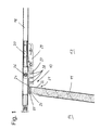
Fig. 1 is a detailed view of a hinge mechanism for a door driving device according to an embodiment of the invention; -
Fig. 2 shows the hinge mechanism ofFig. 1 and a further door panel; -
Fig. 3 shows an overview of an entire door panel driving arrangement including a door, a driving mechanism and the hinge mechanism ofFig. 1 ; -
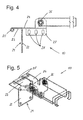
Fig. 4 shows the hinge mechanism ofFig. 1 in the same perspective asFig. 1 in more detail, and -
Fig. 5 is a three-dimensional view of the hinge mechanism ofFig. 1 . - Below, an embodiment of the
hinge mechanism 10 is described in more detail with reference to the above mentionedFigures 1 to 5 , in which same reference numerals denote same parts. - The present invention can be used for opening and closing sectional doors, side sectional doors, up-and-over doors, having a drive mechanism or actuator of preferably an automa tic type. An
upper door panel 11 is illustrated, which forms together with a plurality of further door panels 12 a sectional door. This sectional door is provided for opening and closing an entrance into a room. Thus, the surface of the door or door panel facing to theinside 13 of this room when the door is closed is referred to as inside surface, and the surface of the door or door panel facing to theoutside 14 when the door is closed is referred to as outside surface in this specification. Naturally, when the door is opened and arranged below the ceiling, the inside surface is facing downwards and the outside surface is facing the ceiling. Alldoor panels 12, except theupper door panel 11, are provided at their side edges withrollers 15 which are guided in arail 16 which is provided on both sides of the door. Therail 16 has a vertical part which is provided in parallel and on both sides of the closed door and a horizontal part which is provided below and in parallel to aceiling 17 for holding the door below theceiling 17 in an opened position. The horizontal and vertical parts of therail 16 are connected via an arch having the shape of a quarter circle. Directly attached to theceiling 17 or with a clearance in between and below theceiling 17 there is provided adriving rail 18. Thedriving rail 18 is provided in parallel to the guidingrails 16 and positioned substantially in the middle of the door, or preferably offset from the middle by a certain extent in order not to interfere with a lock of the door which is usually extending vertically in the middle of the door. Thedriving rail 18 is provided on its end, facing away from the door, with a drivingmotor 19 for actuating the opening and closing movement of the door via a driving sled 20 moved by thedriving motor 19 and guided in thedriving rail 18. - The
upper door panel 11 is connected with the drivingsled 20 via thehinge mechanism 10 which is explained in the following. Thehinge mechanism 10 comprises a fitting 21 having an attachment secti on 22 and alever section 23, and abracket 24. The fitting 21 and thebracket 24 are rotatably connected via ahinge 25 for rotation about a hinge axis. Theattachment section 22 is supposed to be mounted to the inside surface of theupper door panel 11 in an upper middle area of theupper door panel 11. The fitting 21 is formed as an angle plate, such that thelever section 23 is perpendicular to theattachment section 22 and projecting from theattachment section 22 in an outwards direction, which is the direction from the inside surface of thedoor panel 11 towards the outside surface of thedoor panel 11. Instead of theattachment section 22 and thelever section 23 being perpendicular, their angle can deviate for example +/ - 20 degrees, +/- 15 degrees, +/- 10 degrees, +/- 5 degrees, or some angle in between these values from perpendicular. At the outside end of thelever section 23 is bent downwards in a rounded form such that the outside end has a tubular shape. Thebracket 24 has a flat horse shoe shape at one end, wherein one outside end of the horse shoe shape is bend downwards in a rounded form such that this outside end has a tubular shape corresponding to the tubular shape formed at the outside end of thelever section 23. However, it is also possible that both outside ends of the horse shoe shape are bend downwards in a rounded form to form a tubular shape at both ends. The tubular shaped end of thelever section 23 is arranged in between the outside ends of the horse shoe shape. Then a bolt or a pin is stuck through all of the tubular shaped ends in order to form thehinge 25. - Alternatively, the
lever section 23 of the fitting 21 can be formed in the shape of a horse shoe such that an outer end (end which is facing to the outside) of thebracket 24 is arranged in between the outer ends (the horse shoe ends) of the lever section. The outer ends would be provided with the tubular shape for forming the hinge as describ ed above. Or in other words, the connected sections of the fitting and the bracket are interchanged compared to the above described embodiment. This alternative provides the same functionality and might be even cheaper to manufacture. - The end of the
bracket 24, which is opposite to thehinge 25, is provided with two projections extending towards theceiling 17. At these projections, twoball bearings 26 are attached. Theball bearings 26 comprise a set of bearing balls, an inner ring and an outer ring, as well known. The outer rings of theseball bearings 26 are guided in the drivingtrack 18. Further, the end of thebracket 24, which is opposite to thehinge 25, is provided with twoprojections 27, which extend away from theceiling 17. These twoprojections 27 are provided with threeholes 28 for attaching a drivingrod 29, which has a flat longitudinal shape. The drivingrod 29 is provided with pins which fit into theholes 28 and thus connect the drivingrod 29 with thebracket 24. The center of the drivingrod 29 and the end which is opposite to the pins are connected with thesled 20. Thus, the connection between thesled 20 and the drivingrod 29, and the connection between the drivingrod 29 and thebracket 24 transmits the force for opening and closing the door. Due each of these two connections having more than one connection point, thebracket 26 is kept non-rotatably with respect to the guidingtrack 18 and shifted in parallel to the guidingrail 18, preferably only allowed to be shifted in parallel to the guidingrail 18. In this embodiment, thebracket 24 is formed of two pieces having a mirror-inverted shape (with respect to a plane along the drivingrail 18 and perpendicular to the ceiling 17). The fitting 21 is formed monolithically in this embodiment. - It is explicitly intended that the teaching of this invention covers any combination of the above described aspects of this embodiment.
- While the invention has been illustrated and described in detail in the drawings and foregoing description, such illustration and description are to be considered illustrative or exemplary and not restrictive and it is not intended to limit the invention to the disclosed embodiment. The mere fact that certain measures are recited in mutually different dependent claims does not indicate that a comb ination of these measures cannot be used advantageously. Any reference signs in the claims should not be construed as limiting the scope of the invention.
Claims (10)
- Hinge mechanism (10) for connecting a door panel (11) to a door driving device, comprising:a fitting (21) having an attachment section (22) for attachment to an inside surface of the door panel (11), and a lever section (23) which is adapted to extend above an upper edge of the door panel (11) in an outwards direction;a bracket (24) for attachment to a driving mechanism, anda hinge (25) connecting the fitting (21) and the bracket (24) rotatably about a hinge axis, the hinge (25) being located at the outside end of the lever section (23).
- Hinge mechanism (10) according to claim 1, wherein the hinge axis is positioned in the area of an upper outside edge of the door panel (10).
- Hinge mechanism (10) according to one of the preceding claims, wherein the lever section (23) and the attachment section (22) are perpendicular to each other.
- Hinge mechanism (10) according to on e of the preceding claims, wherein the lever section (23) and the bracket (24) are substantially parallel to each other in a closed state of the door panel (11), and form an angle on the inside with the hinge axis as a center when the door panel (11) is opened.
- Hinge mechanism (10) according to one of the preceding claims, wherein the bracket (24) is adapted to be connected to a sled (20) of the driving mechanism.
- Hinge mechanism (10) according to claim 5, wherein the b racket (24) is shiftable in parallel to a driving rail (18) which is guiding the sled (20).
- Hinge mechanism (10) according to one of the preceding claims, wherein the bracket (24) is provided with bearings (26) for guiding the bracket (24) in a rail (18) of the driving mechanism.
- Door panel driving arrangement, comprising:a door panel (11);a driving mechanism, anda hinge mechanism (10) according to one of the preceding claims.
- Door panel driving arrangement according to claim 8, comprising a door having more than one door panels (11, 12) which are rotatably connected with each other, wherein the hinge mechanism (10) is attached to an uppermost one (11) of the door panels (11, 12).
- Door panel driving arrangement according to claim 8 or 9, wherein the driving mechanism comprises a motor (19), a sled (20) and a driving rail (18) for guiding the sled (20).
Applications Claiming Priority (1)
| Application Number | Priority Date | Filing Date | Title |
|---|---|---|---|
| SE1250492 | 2012-05-14 |
Publications (2)
| Publication Number | Publication Date |
|---|---|
| EP2664740A2 true EP2664740A2 (en) | 2013-11-20 |
| EP2664740A3 EP2664740A3 (en) | 2018-01-24 |
Family
ID=48444142
Family Applications (1)
| Application Number | Title | Priority Date | Filing Date |
|---|---|---|---|
| EP13167669.4A Withdrawn EP2664740A3 (en) | 2012-05-14 | 2013-05-14 | Hinge mechanism for connecting a door panel to a door driving device |
Country Status (1)
| Country | Link |
|---|---|
| EP (1) | EP2664740A3 (en) |
Citations (1)
| Publication number | Priority date | Publication date | Assignee | Title |
|---|---|---|---|---|
| DE4003218A1 (en) | 1990-02-03 | 1991-08-14 | Rudolf Ing Grad Schneider | Counterbalanced sectional door - has weight counterbalanced by torsion spring and safety catch to hold door if spring breaks |
Family Cites Families (4)
| Publication number | Priority date | Publication date | Assignee | Title |
|---|---|---|---|---|
| US3695332A (en) * | 1970-05-25 | 1972-10-03 | Steiner American Corp | Door operating mechanism |
| GB1480733A (en) * | 1974-07-12 | 1977-07-20 | King W | Apparatus for use in opening doors |
| US20040034969A1 (en) * | 2002-08-20 | 2004-02-26 | Thomas Wegman | Cabinet hinge installable by one person |
| DE102004059895A1 (en) * | 2003-12-17 | 2005-09-01 | Weil, Lothar | Remote controlled electrically-operated garage swing door has battery backup power supply |
-
2013
- 2013-05-14 EP EP13167669.4A patent/EP2664740A3/en not_active Withdrawn
Patent Citations (1)
| Publication number | Priority date | Publication date | Assignee | Title |
|---|---|---|---|---|
| DE4003218A1 (en) | 1990-02-03 | 1991-08-14 | Rudolf Ing Grad Schneider | Counterbalanced sectional door - has weight counterbalanced by torsion spring and safety catch to hold door if spring breaks |
Also Published As
| Publication number | Publication date |
|---|---|
| EP2664740A3 (en) | 2018-01-24 |
Similar Documents
| Publication | Publication Date | Title |
|---|---|---|
| US9512656B2 (en) | Sliding window installation structure including door guide frame having separable segment structure | |
| EP2143682A1 (en) | Doorway device for elevator | |
| US20090288344A1 (en) | Cable Brake Bracket | |
| KR101661080B1 (en) | A Self-Closing Device for Sliding Door capable of multi-direction rotation | |
| RU2670933C2 (en) | Device for opening aircraft door | |
| EP1718833B1 (en) | Door mounting and track system for a sectional door | |
| US20080307709A1 (en) | Dual swing powered gate actuator | |
| AU2017360021B2 (en) | Door driving mechanism for a swing door | |
| JP2008248654A (en) | Door body guide device for sliding door | |
| US10501975B2 (en) | Door, in particular sectional door, and door drive | |
| CN103154414A (en) | Sliding door roller guide, and arrangement of a sliding door roller guide on a piece of furniture | |
| KR200481777Y1 (en) | Moving locking apparatus of elevator hoistway door having secession prevention structure | |
| US20200263468A1 (en) | Lower door section having a folding roller bracket | |
| CN100560464C (en) | Elevator entrance and exit device | |
| JP5078432B2 (en) | Elevator hall door device and its opening / closing device | |
| JP5060209B2 (en) | Platform door equipment | |
| JP2016210563A (en) | Door opening travel preventing device for elevator | |
| JP2015093767A (en) | Elevator door-open travel prevention device and method for installing door-open travel prevention device | |
| KR20140005722A (en) | Door roller assembly for lift-windows | |
| CN101316783A (en) | elevator door device | |
| CN206987646U (en) | Shielding door component and rail system | |
| AU2012231790B2 (en) | Track radius structure | |
| JP7651021B2 (en) | sliding door | |
| EP4063601A1 (en) | Plug door device | |
| KR102735872B1 (en) | Connector for sliding and hinged door |
Legal Events
| Date | Code | Title | Description |
|---|---|---|---|
| PUAI | Public reference made under article 153(3) epc to a published international application that has entered the european phase |
Free format text: ORIGINAL CODE: 0009012 |
|
| AK | Designated contracting states |
Kind code of ref document: A2 Designated state(s): AL AT BE BG CH CY CZ DE DK EE ES FI FR GB GR HR HU IE IS IT LI LT LU LV MC MK MT NL NO PL PT RO RS SE SI SK SM TR |
|
| AX | Request for extension of the european patent |
Extension state: BA ME |
|
| PUAL | Search report despatched |
Free format text: ORIGINAL CODE: 0009013 |
|
| AK | Designated contracting states |
Kind code of ref document: A3 Designated state(s): AL AT BE BG CH CY CZ DE DK EE ES FI FR GB GR HR HU IE IS IT LI LT LU LV MC MK MT NL NO PL PT RO RS SE SI SK SM TR |
|
| AX | Request for extension of the european patent |
Extension state: BA ME |
|
| RIC1 | Information provided on ipc code assigned before grant |
Ipc: E05D 5/06 20060101ALN20171220BHEP Ipc: E05F 15/16 00000000AFI20171220BHEP Ipc: E05D 15/24 20060101ALI20171220BHEP |
|
| STAA | Information on the status of an ep patent application or granted ep patent |
Free format text: STATUS: REQUEST FOR EXAMINATION WAS MADE |
|
| 17P | Request for examination filed |
Effective date: 20180626 |
|
| RBV | Designated contracting states (corrected) |
Designated state(s): AL AT BE BG CH CY CZ DE DK EE ES FI FR GB GR HR HU IE IS IT LI LT LU LV MC MK MT NL NO PL PT RO RS SE SI SK SM TR |
|
| RIC1 | Information provided on ipc code assigned before grant |
Ipc: E05F 15/16 20181130AFI20171220BHEP Ipc: E05D 15/24 20060101ALI20171220BHEP Ipc: E05D 5/06 20060101ALN20171220BHEP |
|
| RIC1 | Information provided on ipc code assigned before grant |
Ipc: E05D 5/06 20060101ALN20171220BHEP Ipc: E05D 15/24 20060101ALI20171220BHEP Ipc: E05F 15/16 20060101AFI20171220BHEP |
|
| STAA | Information on the status of an ep patent application or granted ep patent |
Free format text: STATUS: EXAMINATION IS IN PROGRESS |
|
| 17Q | First examination report despatched |
Effective date: 20190329 |
|
| GRAP | Despatch of communication of intention to grant a patent |
Free format text: ORIGINAL CODE: EPIDOSNIGR1 |
|
| STAA | Information on the status of an ep patent application or granted ep patent |
Free format text: STATUS: GRANT OF PATENT IS INTENDED |
|
| RIC1 | Information provided on ipc code assigned before grant |
Ipc: E05D 5/06 20060101ALN20200602BHEP Ipc: E05F 15/67 20150101ALI20200602BHEP Ipc: E05D 15/24 20060101ALI20200602BHEP Ipc: E05F 15/681 20150101ALI20200602BHEP Ipc: E05D 3/02 20060101ALN20200602BHEP Ipc: E05F 15/668 20150101AFI20200602BHEP |
|
| INTG | Intention to grant announced |
Effective date: 20200707 |
|
| STAA | Information on the status of an ep patent application or granted ep patent |
Free format text: STATUS: THE APPLICATION IS DEEMED TO BE WITHDRAWN |
|
| 18D | Application deemed to be withdrawn |
Effective date: 20201118 |