EP2664504B1 - Method and polishing device for polishing a vehicle tyre - Google Patents
Method and polishing device for polishing a vehicle tyre Download PDFInfo
- Publication number
- EP2664504B1 EP2664504B1 EP13167571.2A EP13167571A EP2664504B1 EP 2664504 B1 EP2664504 B1 EP 2664504B1 EP 13167571 A EP13167571 A EP 13167571A EP 2664504 B1 EP2664504 B1 EP 2664504B1
- Authority
- EP
- European Patent Office
- Prior art keywords
- tyre
- vehicle
- washing
- polishing
- polishing agent
- Prior art date
- Legal status (The legal status is an assumption and is not a legal conclusion. Google has not performed a legal analysis and makes no representation as to the accuracy of the status listed.)
- Active
Links
Images


Classifications
-
- B—PERFORMING OPERATIONS; TRANSPORTING
- B60—VEHICLES IN GENERAL
- B60S—SERVICING, CLEANING, REPAIRING, SUPPORTING, LIFTING, OR MANOEUVRING OF VEHICLES, NOT OTHERWISE PROVIDED FOR
- B60S3/00—Vehicle cleaning apparatus not integral with vehicles
- B60S3/04—Vehicle cleaning apparatus not integral with vehicles for exteriors of land vehicles
- B60S3/042—Wheel cleaning devices
-
- B—PERFORMING OPERATIONS; TRANSPORTING
- B08—CLEANING
- B08B—CLEANING IN GENERAL; PREVENTION OF FOULING IN GENERAL
- B08B3/00—Cleaning by methods involving the use or presence of liquid or steam
- B08B3/02—Cleaning by the force of jets or sprays
Definitions
- the invention relates to polishing a vehicle tyre.
- the washing apparatus may comprise one or more fixedly positioned washing devices, for instance, in relation to which a vehicle moves while the washing device washes the surface or part of the vehicle facing the washing device.
- the washing apparatus may also comprise one or more movably positioned washing devices that are arranged to move in relation to a stationary vehicle.
- the washing apparatuses described above may also have a polishing device for polishing the side of a vehicle tyre.
- a known polishing device has long foam-plastic pieces which are fixed to a floor structure and to which polishing agent is sprayed from the inside. As the vehicle moves through the polishing device, the foam-plastic pieces are pressed against the side of the tyre in its bottom part, whereby the polishing agent rubs onto the tyre.
- the side of the tyre on its entire circumference is polished as, while the vehicle moves forward, the tyre rotates at least once around its entire circumference with the foam-plastic pieces pressing against the side of the tyre in its bottom part.
- said foam-plastic pieces are replaced by long and narrow rotating brushes in the longitudinal direction of the vehicle. Polishing agent is sprayed to the rotating brush that rubs it into the side of the tyre in its bottom part.
- the side of the tyre on its entire circumference is polished as, while the vehicle moves forward, the tyre rotates at least once around its entire circumference with the brushes pressing against the side of the tyre in its bottom part.
- a third known polishing device has a spray nozzle arranged on a guide rail fastened to the floor. As the vehicle moves forward through the polishing device, the spray nozzles also moves forward on its guide rail with the vehicle tyre and sprays polishing agent on the side of the tyre in its bottom part. The side of the tyre on its entire circumference is polished as, while the vehicle moves forward, the tyre rotates at least once around its entire circumference with the spray nozzle spraying polishing agent on the side of the tyre in its bottom part.
- a fourth known polishing device comprises in the longitudinal direction of a vehicle several consecutively positioned fixed spray nozzles for spraying polishing agent on the tyre.
- the polishing device further comprises a switch runner which is positioned on the floor and on which the vehicle moves forward. As the tyre of the vehicle arrives at a specific switch in the switch runner, the spray nozzle corresponding to said switch sprays polishing agent on the side of the tyre in its bottom part.
- the side of the tyre on its entire circumference is polished as, while the vehicle moves forward, the tyre rotates at least once around its entire circumference, and as the vehicle tyre arrives at a switch on the switch runner, the switch directs the corresponding spray nozzle to spray polishing agent on the side of the tyre in its bottom part.
- KR-publication 2011 0126370 A discloses a tyre washing device provided with a tyre washing brush.
- the object of this invention is to develop a novel type of method and polishing device for polishing a vehicle tyre.
- the method for polishing a vehicle tyre in accordance with the invention is characterized by the features of independent claim 1.
- the arrangement comprising a tyre washing device intended for washing a side and rim of the vehicle tyre and a polishing device for polishing the vehicle tyre in accordance with the invention is characterized by the features of independent claim 5.
- At least one polishing agent application means for a vehicle tyre is moved in relation to a tyre of a stationary vehicle and the polishing agent is applied to the side of the vehicle tyre as the polishing agent application means moves in relation to the tyre of the stationary vehicle.
- the solution may be implemented with a structurally simple and thus also reliable polishing device that may be an independently operating device or that may easily be integrated as part of a portal type washing apparatus, for instance, in which case the solution is easy to take into use through retrofitting into washing apparatuses already in use.
- it is possible to avoid a problem that occurs in some prior-art solutions, that is, the extension of the length of the space reserved for the washing apparatus or of the wash tunnel due to the fact that that it is necessary to reserve an extra distance of at least about three metres for the polishing device so that the vehicle tyre can rotate at least once around as the vehicle moves forward during the polishing of the tyre.
- the polishing agent is applied to the side of a vehicle tyre by spraying it on the vehicle tyre.
- the polishing agent spray is directed to a vehicle tyre as a narrow fan-shaped spray.
- the spray distance of the polishing agent from a vehicle tyre is altered on the basis of the tyre size and/or profile.
- the rim of a vehicle tyre is covered during the application of the polishing agent to prevent the polishing agent from spreading on the rim of the vehicle tyre.
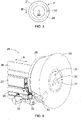
- FIG 1 is a schematic front view of a vehicle 1 washing apparatus 3 with a vehicle 1 tyre 3 polishing device 9, and Figure 2 is a schematic front view of a part of Figure 1 .
- the washing apparatus 3 of Figure 1 comprises a portal-type framework 4 that is arranged to move on rails, for instance, on site in such a manner that during the washing of a vehicle 1, the framework 4 of the washing apparatus 3 moves in the longitudinal direction of the vehicle 1 while the vehicle 1 remains stationary.
- said rails and means for moving the framework 4 of the washing apparatus 3 on said rails are not shown in the figures.
- the washing apparatus 3 of Figure 1 consists of a roof unit 5 that is supported on the framework 4 and in the washing apparatus 3 of Figure 1 forms a vehicle 1 washing device that is intended to wash the upward directed surfaces of the vehicle and possibly the front and rear ends of the vehicle.
- the roof unit 5 comprises a washing brush 6 and its axle 7 that may be rotated by means of an electric motor not shown in Figure 1 for the sake of clarity.
- the washing apparatus 3 of Figure 1 also includes air nozzles 8 for drying the vehicle 1 by blow drying, that is, by blowing air toward the vehicle 1.
- the washing apparatus 3 may also include other washing devices, such as brushes and electric motors to rotate them for washing the sides of the vehicle 1.
- the washing apparatus 3 may comprise washing devices equipped with washing nozzles for brushless washing of vehicles 1.
- the general structure and operational principle of automatically operated washing apparatuses of this type, which are arranged to move in relation to a stationary vehicle, are known per se to a person skilled in the art and will not be described in more detail herein.
- Figure 1 also shows a polishing device 9 for polishing the vehicle 1 tyre 2, in practice, for polishing the side 2' of the vehicle 1 tyre 2.
- the polishing of the side 2' of the vehicle 1 tyre 2 is typically done during the washing of the vehicle 1, either simultaneously with the washing of the vehicle or immediately thereafter.
- the polishing device 9 includes spray nozzles 10 located on both sides of the vehicle 1 and arranged to direct the polishing agent spray 11 to the tyre 2 of the vehicle.
- the spray nozzles 10 are arranged at the outermost end 12' of a nozzle arm 12 that is in the direction of the radius of the vehicle 1 tyre 8.
- the nozzle arm 12 is a tubular structure, in which the inside of the nozzle arm 12 forms a flow channel for supplying polishing agent through the nozzle arm 12 to the spray nozzle 10 in a manner to be described later.
- the spray nozzle 10 can be a separate part attached to the outermost end 12' of the nozzle arm 12, or the spray nozzle 10 can also be achieved merely by the structural design of the outermost end 12' of the nozzle arm 12.
- the polishing device 9 also includes a rotating motor 13, to which the nozzle arm 12 is arranged through the inner end 12" of the nozzle arm 12 in such a manner that the rotating motor 13 may rotate the spray nozzle 10 at the outermost end 12' of the nozzle arm 12 along an annular path.
- the polishing agent is conveyed, fed by a pump 15, to the spray nozzles 10 from the polishing agent container 14 through a connecting tube 16, manifold 17, supply channels 18 and nozzle arms 12, the inner end 12' of the nozzle arms 12 being in flow connection with the supply channels 18.
- the nozzle arm 12 is connected to the supply channel 18 by a rotating connector.
- the supply channels 18 are connected to the manifold 17 that is connected through a connecting tube 16 and pump 15 to the polishing agent container 14.
- the polishing agent sprays 11 are provided by means of pressure generated by the pump 15, and the spray nozzles 10 direct the polishing agent spray 11 to the tyre 8 of the vehicle.
- the operation of the pump 15 is controlled by a control unit 19 that is connected to the pump 15 via a control line 20 that is shown as an arrow 20 from the control unit 19 to the pump 15.
- the operation of the rotating motor 13 is also controlled by a control unit 19 that is connected to the rotating motor 13 via a control line 21 that is shown as an arrow 21 from the control unit 19 to the rotating motor 13.
- the control unit 19 is arranged to start the pump 14 when the polishing device 9 and especially the spray nozzles 10 are at the location of the tyre 8.
- the control unit 19 may obtain information on the location of the tyre from a special detection unit that detects the location of the tyre and may be part of the polishing device 9 or washing apparatus 3.
- the control unit 19 also starts the rotating motor 13, whereby the spray nozzle 10 at the outermost end 12' of the nozzle arm 12 rotates as shown schematically in Figure 3 in the rotating direction shown by arrow R, for instance, along a path 22 in the shape of the vehicle 1 tyre 2 and sprays polishing agent to the side 2' of the tyre 2.
- the spray nozzle 10 is rotated at least once, but preferably at least twice or more around the circumference of the vehicle 1 tyre 2. To achieve a good polishing result, the tyre is washed before polishing. If the side 2' of the vehicle 1 tyre 2 is washed before applying the polishing agent on the side 2' of the tyre 2, only one or a few spray nozzle 10 rounds, 2 to 4, for example, around the circumference of the tyre 2 suffice to achieve a good polishing result. After the spray nozzle 10 has been rotated a specific number of rounds around the circumference of the tyre 2, the control unit 4 stops the rotating motor 13 and pump 15. While the tyre is being polished, both the vehicle 1 and the framework 5 of the washing apparatus 3, to which at least some of the parts belonging to the polishing device 9 are arranged, remain stationary.
- Figure 3 is a schematic view of the spray nozzle 10 rotating counter-clockwise, but the rotation direction of the spray nozzle 10 may naturally also be clockwise.
- the spray nozzles 10, nozzle arms 12, rotating motors 13, polishing agent container 14, connecting tube 15, manifold 16, supply channels 17 and control unit 18 thus form a polishing device 9 for polishing a vehicle 1 tyre 2 with the spray nozzles 10 forming the actual application means of the polishing device 9 for applying the polishing agent to the tyre and the other parts forming means for supplying the polishing agent to the spray nozzles 10 or means for rotating the spray nozzles in relation to the tyre 2 of the stationary vehicle 1.
- the polishing device 9 is arranged as part of the washing apparatus 3.
- the polishing device 9 could also be implemented as a device that is entirely separate from the washing apparatus 3.
- the spray nozzles 10 form polishing agent application means for applying the polishing agent to the side 2' of the vehicle 1 tyre 2.
- one or more brushes or sponges for applying polishing agent on the side 2' of the vehicle 1 tyre 2 could also be used to apply the polishing agent to the side 2' of the vehicle 1 tyre 2, and said brush or sponge would rub the polishing agent supplied through the supply channel 17 and fastening arm of the brush or sponge corresponding to the nozzle arm 12 to the side of the tyre.
- FIGS 4 and 5 are schematic diagonal front views of a vehicle 1 tyre washing device 25 with a vehicle 1 tyre 2 polishing device 9 arranged thereto
- Figure 6 is a schematic diagonal back view of the vehicle 1 tyre washing device 25 according to Figures 4 and 5
- the vehicle 1 tyre washing device 25 comprises a framework 26 and, as seen in Figures 4 and 5 , a first carriage 27 supported to the top part of the framework 26 and a second carriage 28 supported to the top part of the first carriage 27 in such a manner that the first carriage 27 can move in the direction shown schematically by arrow A in relation to the framework 26 and the second carriage 28 can move in the direction shown schematically by arrow A in relation to both the framework 26 and the first carriage 27.
- a backing plate 29 is attached with a tyre washing brush 30 fastened to it, and feed openings 31 are arranged in the mid-section of the brush in such a manner that tyre washing water and agent can be fed through the tyre washing brush 30 between the tyre washing brush 30 and vehicle tyre.
- Figures 4 to 6 do not show individual bristles of the tyre washing brush 30.
- the tyre washing device 25 further comprises a rotating motor 13 for rotating the backing plate 29 and the tyre washing brush 30 fastened thereto during the washing of the vehicle tyre for instance in the direction shown schematically by arrow R in Figure 5 or back and forth.
- the tyre washing device 25 of Figures 4 to 6 further comprises a nozzle arm 12 located on the back side of the backing plate 29, as seen in relation to the tyre washing brush 30, with a spray nozzle 10 arranged at its outermost end 12' for spraying polishing agent on the side 2' of the vehicle 1 tyre 2.
- the spray nozzle 10 arranged at the outermost end 12' of the nozzle arm 12 is arranged to settle on the back side of the backing plate 29 on its outer circumference, and grooves 32 and 33 are arranged on the outer circumference of the backing plate 29 as well as on the outer circumference of the tyre washing brush 30 in such a manner that the spray nozzle 10 on the outermost end 12' of the nozzle arm 12 resides inside the outer circumference of both the backing plate 29 and tyre washing brush 30.
- Figures 4 to 6 do not show the supply channel 18, pump 15, polishing agent container 14 or control unit 19 connected to the spray nozzle 10 and nozzle arm 12.
- the innermost end 12' of the nozzle arm 12 can be arranged to the motor 13 or backing plate 29, for instance.
- the operating principle of the tyre washing device 25 is essentially as follows.
- feed carriages 27 and 28 are suitably moved with respect to the framework 26 and/or each other in such a manner that the tyre washing brush 30 of the tyre washing device 25 moves toward the vehicle 1 tyre 2 to be washed.
- the tyre washing brush 30 comes into contact with the tyre 2 or preferably slightly before the tyre washing brush 30 comes into contact with the tyre 2
- washing water supply is started through the tyre washing brush 30 and the rotating motor 13 is started, whereby the tyre washing brush 30 begins to rotate in relation to the tyre 2.
- the tyre washing brush 30 is pressed against the tyre 2 and its rim 23 while the tyre washing brush 30 is rotated and washing water is supplied through the tyre washing brush 30.
- washing water supply through the tyre washing brush 30 is stopped and the tyre washing brush 30 is moved away from the tyre 2 by suitably moving the feed carriages 27 and 28 with respect to the framework 26 and/or each other.
- the side 2' of the tyre 2 can be polished with the polishing agent.
- the pump 14 is started to supply the polishing agent from the polishing agent container 13 to the spray nozzle 10.
- the rotating motor 13 if it was switched off after the tyre washing, is started again, in which case the backing plate 29 and with it, the tyre washing brush 30, nozzle arm 12 and spray nozzle 10 also start to rotate in relation to the tyre 2.
- Polishing agent is sprayed from the spray nozzle 10 through the groove 32 in the backing plate 29 and the groove 33 in the tyre washing brush 30 toward the side 2' of the tyre 2 past the bristles in the tyre washing brush 30, whereby the spray nozzle 10 provides a polishing agent spray 11 toward the side 2' of the tyre 2 as shown schematically in Figure 5 .
- the spray nozzle 10 moves in relation to the tyre 2 along an annular path 22 shown schematically in Figure 3 and sprays polishing agent on the side 2' of the tyre 2.
- the entire side of the tyre 2 is polished when the spray nozzle 10 rotates at least once around the circumference of the tyre 2, as already stated earlier.
- the tyre washing brush 30 prior to starting to apply the polishing agent, is moved into contact with the vehicle 1 tyre 2 in such a manner that the tyre washing brush 30 presses lightly against the rim 23 of the vehicle 1 tyre 2.
- the tyre washing brush 30 can be moved toward the vehicle 1 tyre 2 by suitably moving the feed carriages 27 and 28 with respect to the framework 26 and/or each other toward the tyre 2, if the tyre washing brush 30 has already been moved away from the tyre 2 after washing the tyre 2.
- the tyre washing brush 30 can be moved slightly away from the tyre 2.
- the force, with which the tyre washing brush 30 is pressed against the rim 23 of the tyre 2 during polishing may be the same as used during tyre washing, in which only the rim 23 of the tyre 2 was washed.
- the bristles of the tyre washing brush 30 then essentially cover only the rim 23 of the tyre 2 and do not extend to the area of the side 2' of the tyre 2.
- the tyre washing brush 30 was pressed against the tyre 2 using a force that bent the bristles of the tyre washing brush 30 against the side 2 of the tyre 2, the tyre washing brush 30 could be pulled slightly away from the tyre 2 so that the bristles of the tyre washing brush 30 essentially cover only the rim 23 of the tyre 2.
- the tyre washing brush 30 presses against the rim 23 of the vehicle 1 tyre 2, the bristles of the tyre washing brush 30 cover the rim 23 of the vehicle 1 tyre 2, whereby the tyre washing brush 30 prevents the polishing agent spray from ending up on the rim 23 of the tyre 2.
- the tyre washing brush 30 forms a means for preventing the application of the polishing agent on the rim 23 of the vehicle 1 tyre 2 by covering the rim 23 of the vehicle 1 tyre 2 during the application of the polishing agent.
- the tyre washing brush 30 can be moved away from the tyre 2 by moving the carriages 27 and 28 to the position where they are when the tyre washing device 25 is not used.
- the tyre polishing device 9 is thus connected to the tyre washing device 25 at least in respect of some components, such as the nozzle arm 12 and spray nozzle 10.
- the tyre washing device 25 can be arranged to be part of a washing apparatus that may also comprise other devices intended for washing or drying a vehicle and that moves in relation to a stationary vehicle.
- the tyre washing device 25 can also be an independent device separate from other devices intended for washing or drying a vehicle. In both cases, one of the tyre washing devices 25 shown herein is preferably positioned on each side of the vehicle.
- the spray nozzle 10 is preferably selected so as to provide the flat fan-shaped spray shown schematically in Figure 5 .
- the spread angle of the spray nozzle 10 may be 25 to 50 degrees, for example.
- the spread angle of the nozzle may be dimensioned proportional to the used spray pressure, whereby a specific nominal pressure uses a specific spread angle.
- the side 2' of the tyre 2 will then be essentially entirely treated with the polishing agent in such a manner, however, that the polishing agent does not essentially reach the tyre space, the rim 23 of the tyre 2 or the side of the vehicle 1.
- the polishing device 9 is fixed to the washing apparatus 3, but the polishing device according to Figures 1 and 2 can also be arranged to be movable with respect to the framework 4 of the washing apparatus 3 in such a manner that the distance of the spray nozzle from the tyre 2 of the vehicle 1 can be altered on the basis of the tyre size and/or profile.
- Figure 7 is a schematic diagonal front view of a second vehicle 1 tyre 2 polishing device 9 that is not covered by the claimed invention.
- the polishing device 9 shown in Figure 7 resembles the tyre washing device 25 shown in Figures 4 and 5 otherwise, except that the polishing device 9 shown in Figure 7 does not comprise a tyre washing brush 30, but the tyre washing brush 30 has been replaced by a guard ring 34 that will be described later in more detail.
- the polishing device 9 shown in Figure 7 comprises a framework 26, a first carriage 27 supported to the top part of the framework 26 and a second carriage 28 supported to the top part of the first carriage 27 in such a manner that the first carriage 27 can move with respect to the framework 26 and the second carriage 28 can move with respect to both the framework 26 and first carriage 27.
- a backing plate 29 is attached to the end of the second carriage 28.
- the polishing device 9 further comprises a nozzle arm 12 with a spray nozzle 10 arranged at its outermost end 12' for spraying polishing agent on the side 2' of the vehicle 1 tyre 2.
- the innermost end 12' of the nozzle arm 12 can be arranged to the motor 13 or backing plate 29, for instance.
- the polishing device 9 shown in Figure 7 further comprises a guard ring 34 arranged with bearings to the outer circumference of the backing plate 29 in such a manner that the backing plate 29 can turn with respect to the stationary guard ring 34, when the guard ring 34 is pressed against the rim 23 of the vehicle 1 tyre 2 during the polishing of the tyre 2, as will be described in more detail later.
- the guard ring 34 is arranged to extend around the entire outer circumference of the backing plate 29 and to a distance outward from the backing plate 29, away from the framework 26 of the polishing device 9.
- the guard ring 34 When using the polishing device 9 according to Figure 7 to polish the side 2' of a vehicle 1 tyre 2, the guard ring 34 is moved toward the vehicle 1 tyre 2 in such a manner that the guard ring 34 presses lightly against the rim 23 of the vehicle 1 tyre 2 and surrounds the rim 23 of the tyre 2.
- the guard ring 34 can be made of soft rubber, for example, so that the guard ring 34 does not damage the rim 23.
- the guard ring 34 can be moved toward the vehicle 1 tyre 2 by suitably moving the feed carriages 27 and 28 in relation to the framework 26 and/or each other toward the tyre 2.
- the guard ring 34 presses lightly against the rim 23 of the vehicle 1 tyre 2, the guard ring 34 covers the rim 23 of the vehicle 1 tyre 2, whereby the guard ring 34 prevents the polishing agent spray from ending up on the rim 23 during the application of the polishing agent.
- the guard ring 34 remains in place in relation to the tyre 2 by means of the bearings between the guard ring 34 and backing plate 39, and the guard ring 34 does not rotate with respect to the tyre 2 and, thus, cannot scratch the rim 23.
- the guard ring 34 thus forms a means that prevents the application of the polishing agent on the rim 23 of the vehicle 1 tyre 2 by covering rim 23 of the vehicle 1 tyre 2 during the application of the polishing agent.
- a plastic guard plate for instance, to prevent the backing plate 29 from coming into contact with the parts of the tyre 2 rim 23, if the centre of the rim 23 comprises parts extending outward from the rim 23, for instance.
- the polishing device 9 comprises only one spray nozzle 10 on both sides of the vehicle 1.
- the polishing device 1 can also comprise more than one spray nozzle 10, two or three spray nozzles, for example, on both sides of the vehicle 1.
- the spray nozzles 10 on the same side of the vehicle 1 can then be arranged in such a manner that they are around the circumference of a ring at a distance from each other.
- the present polishing devices 9 are simple in structure and, thus, reliable. As already stated above, the present polishing devices 9 can be implemented as devices that are entirely separate from the washing apparatus 3 or they can easily be integrated as part of a portal-type washing apparatus, for example, in which case they are also easy to retrofit into washing apparatuses already in use. At the same time, it is possible to avoid a problem arisen in at least some of the known solutions, that is, the increase in the space reserved for the washing apparatus or in the length of the wash tunnel, when it has been necessary to reserve approximately 2 to 3 metres extra space for the polishing device.
- the polishing agent that has possibly ended up on the sides and rims of the vehicle can be removed.
- the polishing agent that has possibly ended up on the sides and rims of the vehicle can be removed for instance by spraying drying wax on the vehicle and then blowing drying air against the vehicle. The drying wax flushes the polishing agent away from the sides of the vehicle 1 and the rims 23 of the tyres, but the polishing agent remains on the sides of the tyres.
- the drying wax can be sprayed on the surface and tyres of the vehicle from drying wax nozzles 24 arranged on the framework 4 of the washing apparatus 3 shown in Figure 1 , for example, and the drying air can be blown against the vehicle from air nozzles 8 shown in Figure 1 , for example.
- the polishing device 9 is connected to a portal-type washing apparatus 3 that comprises both washing devices for washing a vehicle and drying devices for drying a vehicle.
- the present polishing devices 9 could also be connected to a washing apparatus 3 with no portal-type framework, in which case the washing devices for washing the sides of a vehicle and the drying devices for drying the sides of a vehicle are positioned on vertical poles on both sides of the vehicle, and the means for washing and drying the upward facing surfaces of the vehicle and possibly the front and rear ends of the vehicle can be supported to the ceiling structures of the washing location, for instance.
- the present polishing devices 7 can also be placed in connection with a drying apparatus intended solely for drying a vehicle and comprising means for blowing drying air toward the vehicle.
- the means for applying the drying wax can then be placed either on the same drying apparatus or on another structure of the washing or drying location before said drying equipment.
- the structure of said washing or drying apparatus may also be of some other type than that presented above.
- the polishing device may comprise either one application means or two or more application means placed side by side in the vertical or horizontal direction, which are preferably spray nozzles.
- said one or more application means are moved at the location of the vehicle tyre in relation to the tyre of the stationary vehicle in either horizontal direction, that is, in the longitudinal direction of the vehicle, or in the vertical direction, that is, in the elevation of the vehicle, while simultaneously supplying polishing agent through the application means to the tyre of the vehicle.
- the polishing agent is thus applied on a rectangular area, inside the outline of which the tyre being polished is located. It is also possible that the polishing agent is applied through only one stationary spray nozzle.
- the polishing agent that has ended up on the rim of the tyre and possibly on the side of the vehicle can be removed as described above.
Landscapes
- Engineering & Computer Science (AREA)
- Mechanical Engineering (AREA)
- Vehicle Cleaning, Maintenance, Repair, Refitting, And Outriggers (AREA)
- Grinding And Polishing Of Tertiary Curved Surfaces And Surfaces With Complex Shapes (AREA)
Description
- The invention relates to polishing a vehicle tyre.
- Various automatically operated washing apparatuses are used in automatically washing vehicles. The washing apparatus may comprise one or more fixedly positioned washing devices, for instance, in relation to which a vehicle moves while the washing device washes the surface or part of the vehicle facing the washing device. The washing apparatus may also comprise one or more movably positioned washing devices that are arranged to move in relation to a stationary vehicle.
- The washing apparatuses described above may also have a polishing device for polishing the side of a vehicle tyre. A known polishing device has long foam-plastic pieces which are fixed to a floor structure and to which polishing agent is sprayed from the inside. As the vehicle moves through the polishing device, the foam-plastic pieces are pressed against the side of the tyre in its bottom part, whereby the polishing agent rubs onto the tyre. The side of the tyre on its entire circumference is polished as, while the vehicle moves forward, the tyre rotates at least once around its entire circumference with the foam-plastic pieces pressing against the side of the tyre in its bottom part.
- In another known polishing device, said foam-plastic pieces are replaced by long and narrow rotating brushes in the longitudinal direction of the vehicle. Polishing agent is sprayed to the rotating brush that rubs it into the side of the tyre in its bottom part. In this solution, too, the side of the tyre on its entire circumference is polished as, while the vehicle moves forward, the tyre rotates at least once around its entire circumference with the brushes pressing against the side of the tyre in its bottom part.
- A third known polishing device has a spray nozzle arranged on a guide rail fastened to the floor. As the vehicle moves forward through the polishing device, the spray nozzles also moves forward on its guide rail with the vehicle tyre and sprays polishing agent on the side of the tyre in its bottom part. The side of the tyre on its entire circumference is polished as, while the vehicle moves forward, the tyre rotates at least once around its entire circumference with the spray nozzle spraying polishing agent on the side of the tyre in its bottom part.
- A fourth known polishing device comprises in the longitudinal direction of a vehicle several consecutively positioned fixed spray nozzles for spraying polishing agent on the tyre. The polishing device further comprises a switch runner which is positioned on the floor and on which the vehicle moves forward. As the tyre of the vehicle arrives at a specific switch in the switch runner, the spray nozzle corresponding to said switch sprays polishing agent on the side of the tyre in its bottom part. The side of the tyre on its entire circumference is polished as, while the vehicle moves forward, the tyre rotates at least once around its entire circumference, and as the vehicle tyre arrives at a switch on the switch runner, the switch directs the corresponding spray nozzle to spray polishing agent on the side of the tyre in its bottom part.
-
KR-publication 2011 0126370 A - The object of this invention is to develop a novel type of method and polishing device for polishing a vehicle tyre.
- The method for polishing a vehicle tyre in accordance with the invention is characterized by the features of
independent claim 1. - The arrangement comprising a tyre washing device intended for washing a side and rim of the vehicle tyre and a polishing device for polishing the vehicle tyre in accordance with the invention is characterized by the features of
independent claim 5. - In the solution, at least one polishing agent application means for a vehicle tyre is moved in relation to a tyre of a stationary vehicle and the polishing agent is applied to the side of the vehicle tyre as the polishing agent application means moves in relation to the tyre of the stationary vehicle.
- The solution may be implemented with a structurally simple and thus also reliable polishing device that may be an independently operating device or that may easily be integrated as part of a portal type washing apparatus, for instance, in which case the solution is easy to take into use through retrofitting into washing apparatuses already in use. At the same time, it is possible to avoid a problem that occurs in some prior-art solutions, that is, the extension of the length of the space reserved for the washing apparatus or of the wash tunnel due to the fact that that it is necessary to reserve an extra distance of at least about three metres for the polishing device so that the vehicle tyre can rotate at least once around as the vehicle moves forward during the polishing of the tyre.
- Some embodiments of the solution are disclosed in the dependent claims.
- According to the invention, the polishing agent is applied to the side of a vehicle tyre by spraying it on the vehicle tyre.
- According to a preferred embodiment, the polishing agent spray is directed to a vehicle tyre as a narrow fan-shaped spray.
- According to a particular embodiment, the spray distance of the polishing agent from a vehicle tyre is altered on the basis of the tyre size and/or profile.
- According to a preferred embodiment, the rim of a vehicle tyre is covered during the application of the polishing agent to prevent the polishing agent from spreading on the rim of the vehicle tyre.
- The invention will now be described in greater detail by means of preferred embodiments, with reference to the accompanying drawings, in which:
-
Figure 1 is a schematic front view of a vehicle washing apparatus with a vehicle tyre polishing device connected thereto, -
Figure 2 is a schematic front view of a part ofFigure 1 , -
Figure 3 is a schematic side view of a vehicle tyre, -
Figures 4 and5 are schematic diagonal front views of a vehicle tyre washing device with a vehicle tyre polishing device arranged thereto, -
Figure 6 is a schematic diagonal back view of the vehicle tyre washing device according toFigures 4 and5 , and -
Figure 7 is a schematic diagonal front view of a second vehicle tyre polishing device. - In the figures, some embodiments of the invention are shown simplified for the sake of clarity. Like reference numerals identify like elements in the figures.
-
Figure 1 is a schematic front view of avehicle 1washing apparatus 3 with avehicle 1tyre 3polishing device 9, andFigure 2 is a schematic front view of a part ofFigure 1 . Thewashing apparatus 3 ofFigure 1 comprises a portal-type framework 4 that is arranged to move on rails, for instance, on site in such a manner that during the washing of avehicle 1, theframework 4 of thewashing apparatus 3 moves in the longitudinal direction of thevehicle 1 while thevehicle 1 remains stationary. For the sake of clarity, said rails and means for moving theframework 4 of thewashing apparatus 3 on said rails are not shown in the figures. - The
washing apparatus 3 ofFigure 1 consists of aroof unit 5 that is supported on theframework 4 and in thewashing apparatus 3 ofFigure 1 forms avehicle 1 washing device that is intended to wash the upward directed surfaces of the vehicle and possibly the front and rear ends of the vehicle. Theroof unit 5 comprises awashing brush 6 and itsaxle 7 that may be rotated by means of an electric motor not shown inFigure 1 for the sake of clarity. Thewashing apparatus 3 ofFigure 1 also includesair nozzles 8 for drying thevehicle 1 by blow drying, that is, by blowing air toward thevehicle 1. Thewashing apparatus 3 may also include other washing devices, such as brushes and electric motors to rotate them for washing the sides of thevehicle 1. In addition to or instead of the washing devices equipped with brushes for washing the sides of a car, thewashing apparatus 3 may comprise washing devices equipped with washing nozzles for brushless washing ofvehicles 1. The general structure and operational principle of automatically operated washing apparatuses of this type, which are arranged to move in relation to a stationary vehicle, are known per se to a person skilled in the art and will not be described in more detail herein. -
Figure 1 also shows apolishing device 9 for polishing thevehicle 1tyre 2, in practice, for polishing the side 2' of thevehicle 1tyre 2. The polishing of the side 2' of thevehicle 1tyre 2 is typically done during the washing of thevehicle 1, either simultaneously with the washing of the vehicle or immediately thereafter. - The
polishing device 9 includesspray nozzles 10 located on both sides of thevehicle 1 and arranged to direct thepolishing agent spray 11 to thetyre 2 of the vehicle. Thespray nozzles 10 are arranged at the outermost end 12' of anozzle arm 12 that is in the direction of the radius of thevehicle 1tyre 8. Thenozzle arm 12 is a tubular structure, in which the inside of thenozzle arm 12 forms a flow channel for supplying polishing agent through thenozzle arm 12 to thespray nozzle 10 in a manner to be described later. Thespray nozzle 10 can be a separate part attached to the outermost end 12' of thenozzle arm 12, or thespray nozzle 10 can also be achieved merely by the structural design of the outermost end 12' of thenozzle arm 12. - The
polishing device 9 also includes a rotatingmotor 13, to which thenozzle arm 12 is arranged through theinner end 12" of thenozzle arm 12 in such a manner that the rotatingmotor 13 may rotate thespray nozzle 10 at the outermost end 12' of thenozzle arm 12 along an annular path. - The polishing agent is conveyed, fed by a
pump 15, to thespray nozzles 10 from thepolishing agent container 14 through aconnecting tube 16,manifold 17,supply channels 18 andnozzle arms 12, the inner end 12' of thenozzle arms 12 being in flow connection with thesupply channels 18. Thenozzle arm 12 is connected to thesupply channel 18 by a rotating connector. Thesupply channels 18 are connected to themanifold 17 that is connected through aconnecting tube 16 and pump 15 to thepolishing agent container 14. Thepolishing agent sprays 11 are provided by means of pressure generated by thepump 15, and thespray nozzles 10 direct thepolishing agent spray 11 to thetyre 8 of the vehicle. The operation of thepump 15 is controlled by acontrol unit 19 that is connected to thepump 15 via acontrol line 20 that is shown as anarrow 20 from thecontrol unit 19 to thepump 15. The operation of the rotatingmotor 13 is also controlled by acontrol unit 19 that is connected to the rotatingmotor 13 via acontrol line 21 that is shown as anarrow 21 from thecontrol unit 19 to the rotatingmotor 13. - When using the
polishing device 9, thecontrol unit 19 is arranged to start thepump 14 when thepolishing device 9 and especially thespray nozzles 10 are at the location of thetyre 8. Thecontrol unit 19 may obtain information on the location of the tyre from a special detection unit that detects the location of the tyre and may be part of thepolishing device 9 orwashing apparatus 3. Simultaneously, thecontrol unit 19 also starts therotating motor 13, whereby thespray nozzle 10 at the outermost end 12' of thenozzle arm 12 rotates as shown schematically inFigure 3 in the rotating direction shown by arrow R, for instance, along apath 22 in the shape of thevehicle 1tyre 2 and sprays polishing agent to the side 2' of thetyre 2. Thespray nozzle 10 is rotated at least once, but preferably at least twice or more around the circumference of thevehicle 1tyre 2. To achieve a good polishing result, the tyre is washed before polishing. If the side 2' of thevehicle 1tyre 2 is washed before applying the polishing agent on the side 2' of thetyre 2, only one or afew spray nozzle 10 rounds, 2 to 4, for example, around the circumference of thetyre 2 suffice to achieve a good polishing result. After thespray nozzle 10 has been rotated a specific number of rounds around the circumference of thetyre 2, thecontrol unit 4 stops therotating motor 13 andpump 15. While the tyre is being polished, both thevehicle 1 and theframework 5 of thewashing apparatus 3, to which at least some of the parts belonging to thepolishing device 9 are arranged, remain stationary. -
Figure 3 is a schematic view of thespray nozzle 10 rotating counter-clockwise, but the rotation direction of thespray nozzle 10 may naturally also be clockwise. - In the device shown in
Figures 1 and 2 , thespray nozzles 10,nozzle arms 12, rotatingmotors 13, polishingagent container 14, connectingtube 15,manifold 16,supply channels 17 andcontrol unit 18 thus form apolishing device 9 for polishing avehicle 1tyre 2 with thespray nozzles 10 forming the actual application means of thepolishing device 9 for applying the polishing agent to the tyre and the other parts forming means for supplying the polishing agent to thespray nozzles 10 or means for rotating the spray nozzles in relation to thetyre 2 of thestationary vehicle 1. In the device ofFigures 1 and 2 , thepolishing device 9 is arranged as part of thewashing apparatus 3. However, thepolishing device 9 could also be implemented as a device that is entirely separate from thewashing apparatus 3. - In the
polishing device 9 shown inFigure 1 , thespray nozzles 10 form polishing agent application means for applying the polishing agent to the side 2' of thevehicle 1tyre 2. Instead of thespray nozzles 10, one or more brushes or sponges for applying polishing agent on the side 2' of thevehicle 1tyre 2 could also be used to apply the polishing agent to the side 2' of thevehicle 1tyre 2, and said brush or sponge would rub the polishing agent supplied through thesupply channel 17 and fastening arm of the brush or sponge corresponding to thenozzle arm 12 to the side of the tyre. -
Figures 4 and5 are schematic diagonal front views of avehicle 1tyre washing device 25 with avehicle 1tyre 2polishing device 9 arranged thereto, andFigure 6 is a schematic diagonal back view of thevehicle 1tyre washing device 25 according toFigures 4 and5 . Thevehicle 1tyre washing device 25 comprises aframework 26 and, as seen inFigures 4 and5 , afirst carriage 27 supported to the top part of theframework 26 and asecond carriage 28 supported to the top part of thefirst carriage 27 in such a manner that thefirst carriage 27 can move in the direction shown schematically by arrow A in relation to theframework 26 and thesecond carriage 28 can move in the direction shown schematically by arrow A in relation to both theframework 26 and thefirst carriage 27. At the end of thesecond carriage 27, abacking plate 29 is attached with atyre washing brush 30 fastened to it, and feedopenings 31 are arranged in the mid-section of the brush in such a manner that tyre washing water and agent can be fed through thetyre washing brush 30 between thetyre washing brush 30 and vehicle tyre. For the sake of clarity,Figures 4 to 6 do not show individual bristles of thetyre washing brush 30. Thetyre washing device 25 further comprises arotating motor 13 for rotating thebacking plate 29 and thetyre washing brush 30 fastened thereto during the washing of the vehicle tyre for instance in the direction shown schematically by arrow R inFigure 5 or back and forth. - The
tyre washing device 25 ofFigures 4 to 6 further comprises anozzle arm 12 located on the back side of thebacking plate 29, as seen in relation to thetyre washing brush 30, with aspray nozzle 10 arranged at its outermost end 12' for spraying polishing agent on the side 2' of thevehicle 1tyre 2. Thespray nozzle 10 arranged at the outermost end 12' of thenozzle arm 12 is arranged to settle on the back side of thebacking plate 29 on its outer circumference, andgrooves backing plate 29 as well as on the outer circumference of thetyre washing brush 30 in such a manner that thespray nozzle 10 on the outermost end 12' of thenozzle arm 12 resides inside the outer circumference of both thebacking plate 29 andtyre washing brush 30. For the sake of clarity,Figures 4 to 6 do not show thesupply channel 18, pump 15, polishingagent container 14 orcontrol unit 19 connected to thespray nozzle 10 andnozzle arm 12. The innermost end 12' of thenozzle arm 12 can be arranged to themotor 13 orbacking plate 29, for instance. - The operating principle of the
tyre washing device 25 according toFigures 4 to 6 is essentially as follows. When starting the washing of avehicle 1tyre 2, feedcarriages framework 26 and/or each other in such a manner that thetyre washing brush 30 of thetyre washing device 25 moves toward thevehicle 1tyre 2 to be washed. When thetyre washing brush 30 comes into contact with thetyre 2 or preferably slightly before thetyre washing brush 30 comes into contact with thetyre 2, washing water supply is started through thetyre washing brush 30 and therotating motor 13 is started, whereby thetyre washing brush 30 begins to rotate in relation to thetyre 2. After this, thetyre washing brush 30 is pressed against thetyre 2 and itsrim 23 while thetyre washing brush 30 is rotated and washing water is supplied through thetyre washing brush 30. When the tyre washing program made for thetyre washing device 25 is completed, washing water supply through thetyre washing brush 30 is stopped and thetyre washing brush 30 is moved away from thetyre 2 by suitably moving thefeed carriages framework 26 and/or each other. - After the tyre is washed, the side 2' of the
tyre 2 can be polished with the polishing agent. To start polishing the tyre, thepump 14 is started to supply the polishing agent from the polishingagent container 13 to thespray nozzle 10. Therotating motor 13, if it was switched off after the tyre washing, is started again, in which case thebacking plate 29 and with it, thetyre washing brush 30,nozzle arm 12 andspray nozzle 10 also start to rotate in relation to thetyre 2. Polishing agent is sprayed from thespray nozzle 10 through thegroove 32 in thebacking plate 29 and thegroove 33 in thetyre washing brush 30 toward the side 2' of thetyre 2 past the bristles in thetyre washing brush 30, whereby thespray nozzle 10 provides a polishingagent spray 11 toward the side 2' of thetyre 2 as shown schematically inFigure 5 . As themotor 13 rotates, thespray nozzle 10 moves in relation to thetyre 2 along anannular path 22 shown schematically inFigure 3 and sprays polishing agent on the side 2' of thetyre 2. The entire side of thetyre 2 is polished when thespray nozzle 10 rotates at least once around the circumference of thetyre 2, as already stated earlier. - According to an example, prior to starting to apply the polishing agent, the
tyre washing brush 30 is moved into contact with thevehicle 1tyre 2 in such a manner that thetyre washing brush 30 presses lightly against therim 23 of thevehicle 1tyre 2. Thetyre washing brush 30 can be moved toward thevehicle 1tyre 2 by suitably moving thefeed carriages framework 26 and/or each other toward thetyre 2, if thetyre washing brush 30 has already been moved away from thetyre 2 after washing thetyre 2. Alternatively, if thetyre washing brush 30 is still in contact with thetyre 2 after thetyre 2 has been washed, thetyre washing brush 30 can be moved slightly away from thetyre 2. The force, with which thetyre washing brush 30 is pressed against therim 23 of thetyre 2 during polishing, may be the same as used during tyre washing, in which only therim 23 of thetyre 2 was washed. The bristles of thetyre washing brush 30 then essentially cover only therim 23 of thetyre 2 and do not extend to the area of the side 2' of thetyre 2. Alternatively, if, during the washing of thetyre 2, the side 2' of thetyre 2 was also washed, in which case thetyre washing brush 30 was pressed against thetyre 2 using a force that bent the bristles of thetyre washing brush 30 against theside 2 of thetyre 2, thetyre washing brush 30 could be pulled slightly away from thetyre 2 so that the bristles of thetyre washing brush 30 essentially cover only therim 23 of thetyre 2. - As the
tyre washing brush 30 presses against therim 23 of thevehicle 1tyre 2, the bristles of thetyre washing brush 30 cover therim 23 of thevehicle 1tyre 2, whereby thetyre washing brush 30 prevents the polishing agent spray from ending up on therim 23 of thetyre 2. In this example, thetyre washing brush 30 forms a means for preventing the application of the polishing agent on therim 23 of thevehicle 1tyre 2 by covering therim 23 of thevehicle 1tyre 2 during the application of the polishing agent. After the polishing agent has been applied to the side 2' of thetyre 2, thetyre washing brush 30 can be moved away from thetyre 2 by moving thecarriages tyre washing device 25 is not used. - In the solution of
Figures 4 to 6 , thetyre polishing device 9 is thus connected to thetyre washing device 25 at least in respect of some components, such as thenozzle arm 12 andspray nozzle 10. Thetyre washing device 25 can be arranged to be part of a washing apparatus that may also comprise other devices intended for washing or drying a vehicle and that moves in relation to a stationary vehicle. Thetyre washing device 25 can also be an independent device separate from other devices intended for washing or drying a vehicle. In both cases, one of thetyre washing devices 25 shown herein is preferably positioned on each side of the vehicle. - The
spray nozzle 10 is preferably selected so as to provide the flat fan-shaped spray shown schematically inFigure 5 . The spread angle of thespray nozzle 10 may be 25 to 50 degrees, for example. The spread angle of the nozzle may be dimensioned proportional to the used spray pressure, whereby a specific nominal pressure uses a specific spread angle. - In the solution of
Figures 4 to 6 , it is possible to affect the spray distance formed between thetyre 2 side 2' andspray nozzle 10 by moving thecarriages framework 26 and/or each other. By varying the spray distance and also the spray pressure, it is possible to affect the force or pressure, with which the polishingagent spray 11 hits the side 2' of thetyre 2. Further, the possibility of changing the spray distance makes it possible to affect the width of the polishing spray at the side 2' of thetyre 2, whereby it is possible to ensure that the width of the polishing spray at the side 2' of thetyre 2 corresponds essentially to the dimension of the side 2' of thetyre 2 in the radial direction of thetyre 2. The side 2' of thetyre 2 will then be essentially entirely treated with the polishing agent in such a manner, however, that the polishing agent does not essentially reach the tyre space, therim 23 of thetyre 2 or the side of thevehicle 1. By altering the spray distance, it is thus possible to easily polish tyres of different diameter and/or profile with the same polishing device. In the example ofFigures 1 and 2 , thepolishing device 9 is fixed to thewashing apparatus 3, but the polishing device according toFigures 1 and 2 can also be arranged to be movable with respect to theframework 4 of thewashing apparatus 3 in such a manner that the distance of the spray nozzle from thetyre 2 of thevehicle 1 can be altered on the basis of the tyre size and/or profile. -
Figure 7 is a schematic diagonal front view of asecond vehicle 1tyre 2polishing device 9 that is not covered by the claimed invention. Thepolishing device 9 shown inFigure 7 resembles thetyre washing device 25 shown inFigures 4 and5 otherwise, except that thepolishing device 9 shown inFigure 7 does not comprise atyre washing brush 30, but thetyre washing brush 30 has been replaced by aguard ring 34 that will be described later in more detail. - In the manner of
Figures 4 and5 , thepolishing device 9 shown inFigure 7 comprises aframework 26, afirst carriage 27 supported to the top part of theframework 26 and asecond carriage 28 supported to the top part of thefirst carriage 27 in such a manner that thefirst carriage 27 can move with respect to theframework 26 and thesecond carriage 28 can move with respect to both theframework 26 andfirst carriage 27. Abacking plate 29 is attached to the end of thesecond carriage 28. Thepolishing device 9 further comprises anozzle arm 12 with aspray nozzle 10 arranged at its outermost end 12' for spraying polishing agent on the side 2' of thevehicle 1tyre 2. The innermost end 12' of thenozzle arm 12 can be arranged to themotor 13 orbacking plate 29, for instance. Thepolishing device 9 shown inFigure 7 further comprises aguard ring 34 arranged with bearings to the outer circumference of thebacking plate 29 in such a manner that thebacking plate 29 can turn with respect to thestationary guard ring 34, when theguard ring 34 is pressed against therim 23 of thevehicle 1tyre 2 during the polishing of thetyre 2, as will be described in more detail later. Theguard ring 34 is arranged to extend around the entire outer circumference of thebacking plate 29 and to a distance outward from thebacking plate 29, away from theframework 26 of thepolishing device 9. - When using the
polishing device 9 according toFigure 7 to polish the side 2' of avehicle 1tyre 2, theguard ring 34 is moved toward thevehicle 1tyre 2 in such a manner that theguard ring 34 presses lightly against therim 23 of thevehicle 1tyre 2 and surrounds therim 23 of thetyre 2. Theguard ring 34 can be made of soft rubber, for example, so that theguard ring 34 does not damage therim 23. Theguard ring 34 can be moved toward thevehicle 1tyre 2 by suitably moving thefeed carriages framework 26 and/or each other toward thetyre 2. As theguard ring 34 presses lightly against therim 23 of thevehicle 1tyre 2, theguard ring 34 covers therim 23 of thevehicle 1tyre 2, whereby theguard ring 34 prevents the polishing agent spray from ending up on therim 23 during the application of the polishing agent. When thebacking plate 29 andspray nozzle 10 of thepolishing device 9 rotate in relation to thetyre 2 during the application of the polishing agent, theguard ring 34 remains in place in relation to thetyre 2 by means of the bearings between theguard ring 34 and backing plate 39, and theguard ring 34 does not rotate with respect to thetyre 2 and, thus, cannot scratch therim 23. In the embodiment shown inFigure 7 , theguard ring 34 thus forms a means that prevents the application of the polishing agent on therim 23 of thevehicle 1tyre 2 by coveringrim 23 of thevehicle 1tyre 2 during the application of the polishing agent. On the outward facing surface of thebacking plate 29, in the area defined by theguard ring 34, it is possible to arrange a plastic guard plate, for instance, to prevent thebacking plate 29 from coming into contact with the parts of thetyre 2rim 23, if the centre of therim 23 comprises parts extending outward from therim 23, for instance. - In the examples shown in the figures, the
polishing device 9 comprises only onespray nozzle 10 on both sides of thevehicle 1. However, thepolishing device 1 can also comprise more than onespray nozzle 10, two or three spray nozzles, for example, on both sides of thevehicle 1. The spray nozzles 10 on the same side of thevehicle 1 can then be arranged in such a manner that they are around the circumference of a ring at a distance from each other. Similarly, it is possible to place one or more of the above-mentioned sponges or brushes useable instead of thespray nozzles 10 on both sides of the vehicle. - The
present polishing devices 9 are simple in structure and, thus, reliable. As already stated above, thepresent polishing devices 9 can be implemented as devices that are entirely separate from thewashing apparatus 3 or they can easily be integrated as part of a portal-type washing apparatus, for example, in which case they are also easy to retrofit into washing apparatuses already in use. At the same time, it is possible to avoid a problem arisen in at least some of the known solutions, that is, the increase in the space reserved for the washing apparatus or in the length of the wash tunnel, when it has been necessary to reserve approximately 2 to 3 metres extra space for the polishing device. - After the polishing agent has been applied to the sides 2' of the
vehicle 1tyres 2, the polishing agent that has possibly ended up on the sides and rims of the vehicle can be removed. The polishing agent that has possibly ended up on the sides and rims of the vehicle can be removed for instance by spraying drying wax on the vehicle and then blowing drying air against the vehicle. The drying wax flushes the polishing agent away from the sides of thevehicle 1 and therims 23 of the tyres, but the polishing agent remains on the sides of the tyres. The drying wax can be sprayed on the surface and tyres of the vehicle from dryingwax nozzles 24 arranged on theframework 4 of thewashing apparatus 3 shown inFigure 1 , for example, and the drying air can be blown against the vehicle fromair nozzles 8 shown inFigure 1 , for example. - In the embodiment of
Figure 1 , thepolishing device 9 is connected to a portal-type washing apparatus 3 that comprises both washing devices for washing a vehicle and drying devices for drying a vehicle. Thepresent polishing devices 9 could also be connected to awashing apparatus 3 with no portal-type framework, in which case the washing devices for washing the sides of a vehicle and the drying devices for drying the sides of a vehicle are positioned on vertical poles on both sides of the vehicle, and the means for washing and drying the upward facing surfaces of the vehicle and possibly the front and rear ends of the vehicle can be supported to the ceiling structures of the washing location, for instance. Thepresent polishing devices 7 can also be placed in connection with a drying apparatus intended solely for drying a vehicle and comprising means for blowing drying air toward the vehicle. The means for applying the drying wax can then be placed either on the same drying apparatus or on another structure of the washing or drying location before said drying equipment. When placing thepolishing device 9 in connection with washing or drying apparatus, the structure of said washing or drying apparatus may also be of some other type than that presented above. - According to an embodiment not covered by the claimed invention, the polishing device may comprise either one application means or two or more application means placed side by side in the vertical or horizontal direction, which are preferably spray nozzles. In this embodiment, said one or more application means are moved at the location of the vehicle tyre in relation to the tyre of the stationary vehicle in either horizontal direction, that is, in the longitudinal direction of the vehicle, or in the vertical direction, that is, in the elevation of the vehicle, while simultaneously supplying polishing agent through the application means to the tyre of the vehicle. The polishing agent is thus applied on a rectangular area, inside the outline of which the tyre being polished is located. It is also possible that the polishing agent is applied through only one stationary spray nozzle. The polishing agent that has ended up on the rim of the tyre and possibly on the side of the vehicle can be removed as described above.
- The drawings and the related description are only intended to illustrate the idea of the invention. The invention may vary in detail within the scope of the claims.
Claims (11)
- A method for polishing a vehicle (1) tyre (2), comprising moving at least one vehicle (1) tyre (2) polishing agent application means in relation to a tyre (2) of a stationary vehicle (1) along an annular path (23) formed on the side (2') of the vehicle (1) tyre (2) and applying polishing agent on the side (2') of the vehicle (1) tyre (2) as the application means moves in relation to the tyre (2) of the stationary vehicle (1) and that at least the application means of the polishing device (9) for applying polishing agent on the side (2') of the vehicle (1) tyre (2) is arranged in a tyre washing device (25) intended for washing the side (2') and rim (23) of the vehicle (1) tyre (2), the tyre washing device (25) comprising a rotating motor (13) and at least one tyre washing brush (30) arranged to be rotated by the rotating motor (13) in relation to the vehicle (1) tyre (2), and that polishing agent is applied on the side (2') of the vehicle (1) tyre (2) through a groove (33) arranged on an outer circumference of the tyre washing brush (30) past bristles in the tyre washing brush (30).
- A method as claimed in claim 1, characterised by applying the polishing agent on the side (2') of the vehicle (1) tyre (2) by spraying the polishing agent on the vehicle (1) tyre (2).
- A method as claimed in claim 1 or 2, characterised by covering the rim (23) of the vehicle (1) tyre (2) during the application of the polishing agent to prevent the application of the polishing agent on the rim (23) of the vehicle (1) tyre (2).
- A method as claimed in any one of the preceding claims, characterised in that after the application of the polishing agent, drying wax is sprayed on the vehicle (1) and dry blowing is directed to the vehicle (1) to remove any polishing agent that has ended up on the vehicle (1) and rim (23) of the vehicle (1) tyre (2).
- An arrangement comprising a tyre washing device (25) intended for washing a side (2') and rim (23) of the vehicle (1) tyre (2) and a polishing device (9) for polishing the vehicle (1) tyre (2), the polishing device (9) comprising at least one application means for applying polishing agent on a side (2') of the vehicle (1) tyre (2), the application means being arranged to move in relation to the tyre (2) of a stationary vehicle (1) along an annular path (23) formed on the side (2') of the vehicle (1) tyre (2) and that at least the application means of the polishing device (9) for applying polishing agent on the side (2') of the vehicle (1) tyre (2) is arranged in the tyre washing device (25) intended for washing the side (2') and rim (23) of the vehicle (1) tyre (2), the tyre washing device (25) comprising a rotating motor (13) and at least one tyre washing brush (30) arranged to be rotated by the rotating motor (13) in relation to the vehicle (1) tyre (2), and that the application means for applying polishing agent are arranged to apply polishing agent on the side (2') of the vehicle (1) tyre (2) through a groove (33) arranged on an outer circumference of the tyre washing brush (30) past bristles in the tyre washing brush (30).
- An arrangement as claimed in claim 5, characterised in that the polishing device (7) comprises at least one pump (14) for feeding polishing agent to the application means and at least one motor (13) for moving the application means in relation to the tyre (2) of a stationary vehicle (1).
- An arrangement as claimed in claim 5 or 6, characterised in that the application means is a spray nozzle (10) for spraying polishing agent on the tyre (2) of the vehicle (1).
- An arrangement as claimed in claim 7, characterised in that the spray nozzle (10) is arranged to direct the polishing agent to the vehicle (1) tyre (2) as a narrow fan-shaped spray.
- An arrangement as claimed in claim 7 or 8, characterised in that the spread angle of the spray nozzle (10) is 25 to 50 degrees.
- An arrangement as claimed in any one of claims 5 to 9, characterised in that the polishing device (9) comprises a means (30, 34) for covering the rim (23) of the vehicle (1) tyre (2) during the application of the polishing agent to prevent the application of the polishing agent on the rim (23) of the vehicle (1) tyre (2).
- An arrangement as claimed in any one of claims 5 to 10, characterised in that at least the application means of the polishing device (9) for applying polishing agent on the side (2') of the vehicle (1) tyre (2) is arranged in a vehicle (1) washing apparatus (3), which vehicle (1) washing apparatus (3) comprises at least one washing device for washing a vehicle (1) and which vehicle (1) washing apparatus (3) is arranged to move in relation to a stationary vehicle (1).
Priority Applications (4)
| Application Number | Priority Date | Filing Date | Title |
|---|---|---|---|
| EP22200831.0A EP4140837A1 (en) | 2012-05-16 | 2013-05-14 | Method for polishing a vehicle tyre |
| US14/078,088 US9302653B2 (en) | 2012-12-17 | 2013-11-12 | Method and polishing device for polishing a vehicle tyre |
| CA2833442A CA2833442C (en) | 2012-12-17 | 2013-11-14 | Method and polishing device for polishing a vehicle tyre |
| US15/065,210 US10052645B2 (en) | 2012-12-17 | 2016-03-09 | Method and polishing device for polishing a vehicle tyre |
Applications Claiming Priority (2)
| Application Number | Priority Date | Filing Date | Title |
|---|---|---|---|
| FI20125525 | 2012-05-16 | ||
| FI20126317A FI125289B (en) | 2012-05-16 | 2012-12-17 | Procedure and polisher for polishing a vehicle tire |
Related Child Applications (1)
| Application Number | Title | Priority Date | Filing Date |
|---|---|---|---|
| EP22200831.0A Division EP4140837A1 (en) | 2012-05-16 | 2013-05-14 | Method for polishing a vehicle tyre |
Publications (3)
| Publication Number | Publication Date |
|---|---|
| EP2664504A2 EP2664504A2 (en) | 2013-11-20 |
| EP2664504A3 EP2664504A3 (en) | 2018-02-07 |
| EP2664504B1 true EP2664504B1 (en) | 2022-10-12 |
Family
ID=48484982
Family Applications (2)
| Application Number | Title | Priority Date | Filing Date |
|---|---|---|---|
| EP22200831.0A Pending EP4140837A1 (en) | 2012-05-16 | 2013-05-14 | Method for polishing a vehicle tyre |
| EP13167571.2A Active EP2664504B1 (en) | 2012-05-16 | 2013-05-14 | Method and polishing device for polishing a vehicle tyre |
Family Applications Before (1)
| Application Number | Title | Priority Date | Filing Date |
|---|---|---|---|
| EP22200831.0A Pending EP4140837A1 (en) | 2012-05-16 | 2013-05-14 | Method for polishing a vehicle tyre |
Country Status (4)
| Country | Link |
|---|---|
| EP (2) | EP4140837A1 (en) |
| DK (1) | DK2664504T3 (en) |
| ES (1) | ES2933454T3 (en) |
| FI (1) | FI125289B (en) |
Families Citing this family (1)
| Publication number | Priority date | Publication date | Assignee | Title |
|---|---|---|---|---|
| DE102017124752A1 (en) * | 2017-10-23 | 2019-04-25 | Washtec Holding Gmbh | Apparatus and method for applying a treatment liquid to a wheel of a vehicle |
Citations (3)
| Publication number | Priority date | Publication date | Assignee | Title |
|---|---|---|---|---|
| US5423599A (en) | 1994-05-20 | 1995-06-13 | Curtis Sherod | Wheel mask |
| EP2077211A1 (en) | 2008-01-02 | 2009-07-08 | Ceccato S.p.A. | Automatic washing plant for vehicles and washing procedure thereof |
| KR101156051B1 (en) | 2010-05-17 | 2012-06-21 | 동양기전 주식회사 | Electric brush |
Family Cites Families (6)
| Publication number | Priority date | Publication date | Assignee | Title |
|---|---|---|---|---|
| JPS5353870U (en) * | 1976-10-09 | 1978-05-09 | ||
| DE9000427U1 (en) * | 1990-01-16 | 1991-03-21 | Kleindienst GmbH, 8900 Augsburg | Wheel washing device for vehicle wheels |
| US20060127157A1 (en) * | 2004-12-15 | 2006-06-15 | Louis Sims | Tire polishing system |
| US7582164B1 (en) * | 2008-02-01 | 2009-09-01 | Cleaning Systems, Inc. | Tire dressing system |
| US8383207B2 (en) * | 2009-04-28 | 2013-02-26 | Zep Ip Holding Llc | Configurable application of a tire dressing |
| DE102009037772A1 (en) * | 2009-08-17 | 2011-02-24 | Washtec Holding Gmbh | Device for cleaning vehicle wheels |
-
2012
- 2012-12-17 FI FI20126317A patent/FI125289B/en active IP Right Grant
-
2013
- 2013-05-14 EP EP22200831.0A patent/EP4140837A1/en active Pending
- 2013-05-14 DK DK13167571.2T patent/DK2664504T3/en active
- 2013-05-14 ES ES13167571T patent/ES2933454T3/en active Active
- 2013-05-14 EP EP13167571.2A patent/EP2664504B1/en active Active
Patent Citations (3)
| Publication number | Priority date | Publication date | Assignee | Title |
|---|---|---|---|---|
| US5423599A (en) | 1994-05-20 | 1995-06-13 | Curtis Sherod | Wheel mask |
| EP2077211A1 (en) | 2008-01-02 | 2009-07-08 | Ceccato S.p.A. | Automatic washing plant for vehicles and washing procedure thereof |
| KR101156051B1 (en) | 2010-05-17 | 2012-06-21 | 동양기전 주식회사 | Electric brush |
Non-Patent Citations (2)
| Title |
|---|
| ANONYMOUS: "Betriebsanleitung Portalwaschanlage SoftCare Pro/ SoftCare Takt", WASHTEC, no. 206009, 29 May 2007 (2007-05-29), pages 1 - 6, XP093106885 |
| ANONYMOUS: "Ersatzteilliste softcare pro ", WASHTEC, no. 206012, 7 May 2008 (2008-05-07), pages 1 - 36, XP093106881 |
Also Published As
| Publication number | Publication date |
|---|---|
| FI125289B (en) | 2015-08-14 |
| DK2664504T3 (en) | 2022-12-05 |
| ES2933454T3 (en) | 2023-02-09 |
| FI20126317L (en) | 2013-11-17 |
| EP2664504A2 (en) | 2013-11-20 |
| EP4140837A1 (en) | 2023-03-01 |
| EP2664504A3 (en) | 2018-02-07 |
Similar Documents
| Publication | Publication Date | Title |
|---|---|---|
| US9302653B2 (en) | Method and polishing device for polishing a vehicle tyre | |
| US7806128B2 (en) | No water spill automatic steam car wash system | |
| US6679275B2 (en) | Vehicle washing installation | |
| CA2605798C (en) | Gantry method of washing vehicles | |
| US11203328B2 (en) | Vehicle drying assembly | |
| JP5240224B2 (en) | Car wash machine and car wash method | |
| CN108608997A (en) | A kind of planer-type automatic car washing machine | |
| EP1900581A2 (en) | Vehicle wash system including multiple overhead bridges | |
| JP4267794B2 (en) | Car wash equipment | |
| JP2014031040A (en) | Washing equipment | |
| JP2015147566A (en) | Car washing machine | |
| CN109018243A (en) | Window cleaning equipment and ship | |
| US8424480B2 (en) | Vehicle tire coating apparatus | |
| EP2664504B1 (en) | Method and polishing device for polishing a vehicle tyre | |
| JP2022032126A (en) | washing machine | |
| JP2013095234A (en) | Car wash machine | |
| JPH08154880A (en) | Automatic cleaning device | |
| EP2181902B1 (en) | Double-gantry car wash installation, and corresponding method | |
| EP1527968A3 (en) | Improved car wash installation and corresponding process for washing | |
| JP2009073300A (en) | Car washing facility | |
| CN215097487U (en) | Automatic car washer of compact length | |
| CN207931687U (en) | A kind of reciprocating automatic car washing machine | |
| CN220785709U (en) | Automatic car washer is with blowing water installation | |
| JP2018172054A (en) | Vehicle washing machine | |
| US20060102209A1 (en) | Device with moveabe portico to automatically wash vehicles |
Legal Events
| Date | Code | Title | Description |
|---|---|---|---|
| PUAI | Public reference made under article 153(3) epc to a published international application that has entered the european phase |
Free format text: ORIGINAL CODE: 0009012 |
|
| AK | Designated contracting states |
Kind code of ref document: A2 Designated state(s): AL AT BE BG CH CY CZ DE DK EE ES FI FR GB GR HR HU IE IS IT LI LT LU LV MC MK MT NL NO PL PT RO RS SE SI SK SM TR |
|
| AX | Request for extension of the european patent |
Extension state: BA ME |
|
| PUAL | Search report despatched |
Free format text: ORIGINAL CODE: 0009013 |
|
| AK | Designated contracting states |
Kind code of ref document: A3 Designated state(s): AL AT BE BG CH CY CZ DE DK EE ES FI FR GB GR HR HU IE IS IT LI LT LU LV MC MK MT NL NO PL PT RO RS SE SI SK SM TR |
|
| AX | Request for extension of the european patent |
Extension state: BA ME |
|
| RIC1 | Information provided on ipc code assigned before grant |
Ipc: B60S 3/04 20060101AFI20180102BHEP |
|
| STAA | Information on the status of an ep patent application or granted ep patent |
Free format text: STATUS: REQUEST FOR EXAMINATION WAS MADE |
|
| RBV | Designated contracting states (corrected) |
Designated state(s): AL AT BE BG CH CY CZ DE DK EE ES FI FR GB GR HR HU IE IS IT LI LT LU LV MC MK MT NL NO PL PT RO RS SE SI SK SM TR |
|
| 17P | Request for examination filed |
Effective date: 20180807 |
|
| STAA | Information on the status of an ep patent application or granted ep patent |
Free format text: STATUS: EXAMINATION IS IN PROGRESS |
|
| 17Q | First examination report despatched |
Effective date: 20190510 |
|
| GRAP | Despatch of communication of intention to grant a patent |
Free format text: ORIGINAL CODE: EPIDOSNIGR1 |
|
| STAA | Information on the status of an ep patent application or granted ep patent |
Free format text: STATUS: GRANT OF PATENT IS INTENDED |
|
| INTG | Intention to grant announced |
Effective date: 20211202 |
|
| GRAJ | Information related to disapproval of communication of intention to grant by the applicant or resumption of examination proceedings by the epo deleted |
Free format text: ORIGINAL CODE: EPIDOSDIGR1 |
|
| STAA | Information on the status of an ep patent application or granted ep patent |
Free format text: STATUS: EXAMINATION IS IN PROGRESS |
|
| INTC | Intention to grant announced (deleted) | ||
| GRAP | Despatch of communication of intention to grant a patent |
Free format text: ORIGINAL CODE: EPIDOSNIGR1 |
|
| STAA | Information on the status of an ep patent application or granted ep patent |
Free format text: STATUS: GRANT OF PATENT IS INTENDED |
|
| INTG | Intention to grant announced |
Effective date: 20220509 |
|
| GRAS | Grant fee paid |
Free format text: ORIGINAL CODE: EPIDOSNIGR3 |
|
| GRAA | (expected) grant |
Free format text: ORIGINAL CODE: 0009210 |
|
| STAA | Information on the status of an ep patent application or granted ep patent |
Free format text: STATUS: THE PATENT HAS BEEN GRANTED |
|
| RAP3 | Party data changed (applicant data changed or rights of an application transferred) |
Owner name: TAMMERMATIC OY |
|
| RIN1 | Information on inventor provided before grant (corrected) |
Inventor name: MAEKELAE, ARTO Inventor name: KOHONEN, ARI |
|
| AK | Designated contracting states |
Kind code of ref document: B1 Designated state(s): AL AT BE BG CH CY CZ DE DK EE ES FI FR GB GR HR HU IE IS IT LI LT LU LV MC MK MT NL NO PL PT RO RS SE SI SK SM TR |
|
| REG | Reference to a national code |
Ref country code: GB Ref legal event code: FG4D |
|
| REG | Reference to a national code |
Ref country code: CH Ref legal event code: EP |
|
| REG | Reference to a national code |
Ref country code: DE Ref legal event code: R096 Ref document number: 602013082657 Country of ref document: DE |
|
| REG | Reference to a national code |
Ref country code: IE Ref legal event code: FG4D |
|
| REG | Reference to a national code |
Ref country code: AT Ref legal event code: REF Ref document number: 1523986 Country of ref document: AT Kind code of ref document: T Effective date: 20221115 |
|
| REG | Reference to a national code |
Ref country code: DK Ref legal event code: T3 Effective date: 20221128 |
|
| REG | Reference to a national code |
Ref country code: NO Ref legal event code: T2 Effective date: 20221012 |
|
| REG | Reference to a national code |
Ref country code: SE Ref legal event code: TRGR |
|
| REG | Reference to a national code |
Ref country code: ES Ref legal event code: FG2A Ref document number: 2933454 Country of ref document: ES Kind code of ref document: T3 Effective date: 20230209 |
|
| REG | Reference to a national code |
Ref country code: LT Ref legal event code: MG9D |
|
| REG | Reference to a national code |
Ref country code: NL Ref legal event code: MP Effective date: 20221012 |
|
| REG | Reference to a national code |
Ref country code: AT Ref legal event code: MK05 Ref document number: 1523986 Country of ref document: AT Kind code of ref document: T Effective date: 20221012 |
|
| PG25 | Lapsed in a contracting state [announced via postgrant information from national office to epo] |
Ref country code: NL Free format text: LAPSE BECAUSE OF FAILURE TO SUBMIT A TRANSLATION OF THE DESCRIPTION OR TO PAY THE FEE WITHIN THE PRESCRIBED TIME-LIMIT Effective date: 20221012 |
|
| PG25 | Lapsed in a contracting state [announced via postgrant information from national office to epo] |
Ref country code: PT Free format text: LAPSE BECAUSE OF FAILURE TO SUBMIT A TRANSLATION OF THE DESCRIPTION OR TO PAY THE FEE WITHIN THE PRESCRIBED TIME-LIMIT Effective date: 20230213 Ref country code: LT Free format text: LAPSE BECAUSE OF FAILURE TO SUBMIT A TRANSLATION OF THE DESCRIPTION OR TO PAY THE FEE WITHIN THE PRESCRIBED TIME-LIMIT Effective date: 20221012 Ref country code: FI Free format text: LAPSE BECAUSE OF FAILURE TO SUBMIT A TRANSLATION OF THE DESCRIPTION OR TO PAY THE FEE WITHIN THE PRESCRIBED TIME-LIMIT Effective date: 20221012 Ref country code: AT Free format text: LAPSE BECAUSE OF FAILURE TO SUBMIT A TRANSLATION OF THE DESCRIPTION OR TO PAY THE FEE WITHIN THE PRESCRIBED TIME-LIMIT Effective date: 20221012 |
|
| PG25 | Lapsed in a contracting state [announced via postgrant information from national office to epo] |
Ref country code: RS Free format text: LAPSE BECAUSE OF FAILURE TO SUBMIT A TRANSLATION OF THE DESCRIPTION OR TO PAY THE FEE WITHIN THE PRESCRIBED TIME-LIMIT Effective date: 20221012 Ref country code: PL Free format text: LAPSE BECAUSE OF FAILURE TO SUBMIT A TRANSLATION OF THE DESCRIPTION OR TO PAY THE FEE WITHIN THE PRESCRIBED TIME-LIMIT Effective date: 20221012 Ref country code: LV Free format text: LAPSE BECAUSE OF FAILURE TO SUBMIT A TRANSLATION OF THE DESCRIPTION OR TO PAY THE FEE WITHIN THE PRESCRIBED TIME-LIMIT Effective date: 20221012 Ref country code: IS Free format text: LAPSE BECAUSE OF FAILURE TO SUBMIT A TRANSLATION OF THE DESCRIPTION OR TO PAY THE FEE WITHIN THE PRESCRIBED TIME-LIMIT Effective date: 20230212 Ref country code: HR Free format text: LAPSE BECAUSE OF FAILURE TO SUBMIT A TRANSLATION OF THE DESCRIPTION OR TO PAY THE FEE WITHIN THE PRESCRIBED TIME-LIMIT Effective date: 20221012 Ref country code: GR Free format text: LAPSE BECAUSE OF FAILURE TO SUBMIT A TRANSLATION OF THE DESCRIPTION OR TO PAY THE FEE WITHIN THE PRESCRIBED TIME-LIMIT Effective date: 20230113 |
|
| REG | Reference to a national code |
Ref country code: DE Ref legal event code: R026 Ref document number: 602013082657 Country of ref document: DE |
|
| PLBI | Opposition filed |
Free format text: ORIGINAL CODE: 0009260 |
|
| PLAX | Notice of opposition and request to file observation + time limit sent |
Free format text: ORIGINAL CODE: EPIDOSNOBS2 |
|
| PG25 | Lapsed in a contracting state [announced via postgrant information from national office to epo] |
Ref country code: SM Free format text: LAPSE BECAUSE OF FAILURE TO SUBMIT A TRANSLATION OF THE DESCRIPTION OR TO PAY THE FEE WITHIN THE PRESCRIBED TIME-LIMIT Effective date: 20221012 Ref country code: RO Free format text: LAPSE BECAUSE OF FAILURE TO SUBMIT A TRANSLATION OF THE DESCRIPTION OR TO PAY THE FEE WITHIN THE PRESCRIBED TIME-LIMIT Effective date: 20221012 Ref country code: EE Free format text: LAPSE BECAUSE OF FAILURE TO SUBMIT A TRANSLATION OF THE DESCRIPTION OR TO PAY THE FEE WITHIN THE PRESCRIBED TIME-LIMIT Effective date: 20221012 Ref country code: CZ Free format text: LAPSE BECAUSE OF FAILURE TO SUBMIT A TRANSLATION OF THE DESCRIPTION OR TO PAY THE FEE WITHIN THE PRESCRIBED TIME-LIMIT Effective date: 20221012 |
|
| 26 | Opposition filed |
Opponent name: WASHTEC HOLDING GMBH Effective date: 20230712 |
|
| PG25 | Lapsed in a contracting state [announced via postgrant information from national office to epo] |
Ref country code: SK Free format text: LAPSE BECAUSE OF FAILURE TO SUBMIT A TRANSLATION OF THE DESCRIPTION OR TO PAY THE FEE WITHIN THE PRESCRIBED TIME-LIMIT Effective date: 20221012 Ref country code: AL Free format text: LAPSE BECAUSE OF FAILURE TO SUBMIT A TRANSLATION OF THE DESCRIPTION OR TO PAY THE FEE WITHIN THE PRESCRIBED TIME-LIMIT Effective date: 20221012 |
|
| PLBB | Reply of patent proprietor to notice(s) of opposition received |
Free format text: ORIGINAL CODE: EPIDOSNOBS3 |
|
| PG25 | Lapsed in a contracting state [announced via postgrant information from national office to epo] |
Ref country code: SI Free format text: LAPSE BECAUSE OF FAILURE TO SUBMIT A TRANSLATION OF THE DESCRIPTION OR TO PAY THE FEE WITHIN THE PRESCRIBED TIME-LIMIT Effective date: 20221012 |
|
| REG | Reference to a national code |
Ref country code: CH Ref legal event code: PL |
|
| PG25 | Lapsed in a contracting state [announced via postgrant information from national office to epo] |
Ref country code: MC Free format text: LAPSE BECAUSE OF FAILURE TO SUBMIT A TRANSLATION OF THE DESCRIPTION OR TO PAY THE FEE WITHIN THE PRESCRIBED TIME-LIMIT Effective date: 20221012 |
|
| GBPC | Gb: european patent ceased through non-payment of renewal fee |
Effective date: 20230514 |
|
| REG | Reference to a national code |
Ref country code: BE Ref legal event code: MM Effective date: 20230531 |
|
| PG25 | Lapsed in a contracting state [announced via postgrant information from national office to epo] |
Ref country code: MC Free format text: LAPSE BECAUSE OF FAILURE TO SUBMIT A TRANSLATION OF THE DESCRIPTION OR TO PAY THE FEE WITHIN THE PRESCRIBED TIME-LIMIT Effective date: 20221012 Ref country code: LU Free format text: LAPSE BECAUSE OF NON-PAYMENT OF DUE FEES Effective date: 20230514 Ref country code: LI Free format text: LAPSE BECAUSE OF NON-PAYMENT OF DUE FEES Effective date: 20230531 Ref country code: CH Free format text: LAPSE BECAUSE OF NON-PAYMENT OF DUE FEES Effective date: 20230531 |
|
| REG | Reference to a national code |
Ref country code: IE Ref legal event code: MM4A |
|
| PLAB | Opposition data, opponent's data or that of the opponent's representative modified |
Free format text: ORIGINAL CODE: 0009299OPPO |
|
| PG25 | Lapsed in a contracting state [announced via postgrant information from national office to epo] |
Ref country code: IE Free format text: LAPSE BECAUSE OF NON-PAYMENT OF DUE FEES Effective date: 20230514 |
|
| R26 | Opposition filed (corrected) |
Opponent name: WASHTEC HOLDING GMBH Effective date: 20230712 |
|
| PG25 | Lapsed in a contracting state [announced via postgrant information from national office to epo] |
Ref country code: IE Free format text: LAPSE BECAUSE OF NON-PAYMENT OF DUE FEES Effective date: 20230514 Ref country code: GB Free format text: LAPSE BECAUSE OF NON-PAYMENT OF DUE FEES Effective date: 20230514 |
|
| REG | Reference to a national code |
Ref country code: CH Ref legal event code: PK Free format text: DIE PUBLIKATION VOM 27.03.2024 WURDE AM 24.04.2024 IRRTUEMLICHERWEISE ERNEUT PUBLIZIERT. LA PUBLICATION DU 27.03.2024 A ETE REPUBLIEE PAR ERREUR LE 24.04.2024. LA PUBBLICAZIONE DEL 27.03.2024 E STATA ERRONEAMENTE RIPUBBLICATA IL 24.04.2024. |
|
| PG25 | Lapsed in a contracting state [announced via postgrant information from national office to epo] |
Ref country code: BE Free format text: LAPSE BECAUSE OF NON-PAYMENT OF DUE FEES Effective date: 20230531 |
|
| PG25 | Lapsed in a contracting state [announced via postgrant information from national office to epo] |
Ref country code: BG Free format text: LAPSE BECAUSE OF FAILURE TO SUBMIT A TRANSLATION OF THE DESCRIPTION OR TO PAY THE FEE WITHIN THE PRESCRIBED TIME-LIMIT Effective date: 20221012 |
|
| PG25 | Lapsed in a contracting state [announced via postgrant information from national office to epo] |
Ref country code: BG Free format text: LAPSE BECAUSE OF FAILURE TO SUBMIT A TRANSLATION OF THE DESCRIPTION OR TO PAY THE FEE WITHIN THE PRESCRIBED TIME-LIMIT Effective date: 20221012 |
|
| REG | Reference to a national code |
Ref country code: DE Ref legal event code: R082 Ref document number: 602013082657 Country of ref document: DE Representative=s name: WUESTHOFF & WUESTHOFF PATENTANWAELTE UND RECHT, DE |
|
| RDAF | Communication despatched that patent is revoked |
Free format text: ORIGINAL CODE: EPIDOSNREV1 |
|
| PGFP | Annual fee paid to national office [announced via postgrant information from national office to epo] |
Ref country code: DE Payment date: 20250521 Year of fee payment: 13 |
|
| PGFP | Annual fee paid to national office [announced via postgrant information from national office to epo] |
Ref country code: DK Payment date: 20250527 Year of fee payment: 13 |
|
| PGFP | Annual fee paid to national office [announced via postgrant information from national office to epo] |
Ref country code: NO Payment date: 20250523 Year of fee payment: 13 |
|
| PGFP | Annual fee paid to national office [announced via postgrant information from national office to epo] |
Ref country code: IT Payment date: 20250521 Year of fee payment: 13 |
|
| PGFP | Annual fee paid to national office [announced via postgrant information from national office to epo] |
Ref country code: FR Payment date: 20250526 Year of fee payment: 13 |
|
| PG25 | Lapsed in a contracting state [announced via postgrant information from national office to epo] |
Ref country code: CY Free format text: LAPSE BECAUSE OF FAILURE TO SUBMIT A TRANSLATION OF THE DESCRIPTION OR TO PAY THE FEE WITHIN THE PRESCRIBED TIME-LIMIT; INVALID AB INITIO Effective date: 20130514 |
|
| PGFP | Annual fee paid to national office [announced via postgrant information from national office to epo] |
Ref country code: SE Payment date: 20250527 Year of fee payment: 13 |
|
| PG25 | Lapsed in a contracting state [announced via postgrant information from national office to epo] |
Ref country code: HU Free format text: LAPSE BECAUSE OF FAILURE TO SUBMIT A TRANSLATION OF THE DESCRIPTION OR TO PAY THE FEE WITHIN THE PRESCRIBED TIME-LIMIT; INVALID AB INITIO Effective date: 20130514 |
|
| PGFP | Annual fee paid to national office [announced via postgrant information from national office to epo] |
Ref country code: ES Payment date: 20250812 Year of fee payment: 13 |
|
| PG25 | Lapsed in a contracting state [announced via postgrant information from national office to epo] |
Ref country code: TR Free format text: LAPSE BECAUSE OF FAILURE TO SUBMIT A TRANSLATION OF THE DESCRIPTION OR TO PAY THE FEE WITHIN THE PRESCRIBED TIME-LIMIT Effective date: 20221012 |