EP2664487A1 - In-wheel motor driving device - Google Patents
In-wheel motor driving device Download PDFInfo
- Publication number
- EP2664487A1 EP2664487A1 EP12734769.8A EP12734769A EP2664487A1 EP 2664487 A1 EP2664487 A1 EP 2664487A1 EP 12734769 A EP12734769 A EP 12734769A EP 2664487 A1 EP2664487 A1 EP 2664487A1
- Authority
- EP
- European Patent Office
- Prior art keywords
- stator
- motor
- wheel
- rotor
- diameter
- Prior art date
- Legal status (The legal status is an assumption and is not a legal conclusion. Google has not performed a legal analysis and makes no representation as to the accuracy of the status listed.)
- Withdrawn
Links
Images


Classifications
-
- F—MECHANICAL ENGINEERING; LIGHTING; HEATING; WEAPONS; BLASTING
- F16—ENGINEERING ELEMENTS AND UNITS; GENERAL MEASURES FOR PRODUCING AND MAINTAINING EFFECTIVE FUNCTIONING OF MACHINES OR INSTALLATIONS; THERMAL INSULATION IN GENERAL
- F16H—GEARING
- F16H48/00—Differential gearings
- F16H48/20—Arrangements for suppressing or influencing the differential action, e.g. locking devices
-
- B—PERFORMING OPERATIONS; TRANSPORTING
- B60—VEHICLES IN GENERAL
- B60K—ARRANGEMENT OR MOUNTING OF PROPULSION UNITS OR OF TRANSMISSIONS IN VEHICLES; ARRANGEMENT OR MOUNTING OF PLURAL DIVERSE PRIME-MOVERS IN VEHICLES; AUXILIARY DRIVES FOR VEHICLES; INSTRUMENTATION OR DASHBOARDS FOR VEHICLES; ARRANGEMENTS IN CONNECTION WITH COOLING, AIR INTAKE, GAS EXHAUST OR FUEL SUPPLY OF PROPULSION UNITS IN VEHICLES
- B60K1/00—Arrangement or mounting of electrical propulsion units
- B60K1/02—Arrangement or mounting of electrical propulsion units comprising more than one electric motor
-
- B—PERFORMING OPERATIONS; TRANSPORTING
- B60—VEHICLES IN GENERAL
- B60K—ARRANGEMENT OR MOUNTING OF PROPULSION UNITS OR OF TRANSMISSIONS IN VEHICLES; ARRANGEMENT OR MOUNTING OF PLURAL DIVERSE PRIME-MOVERS IN VEHICLES; AUXILIARY DRIVES FOR VEHICLES; INSTRUMENTATION OR DASHBOARDS FOR VEHICLES; ARRANGEMENTS IN CONNECTION WITH COOLING, AIR INTAKE, GAS EXHAUST OR FUEL SUPPLY OF PROPULSION UNITS IN VEHICLES
- B60K17/00—Arrangement or mounting of transmissions in vehicles
- B60K17/34—Arrangement or mounting of transmissions in vehicles for driving both front and rear wheels, e.g. four wheel drive vehicles
- B60K17/356—Arrangement or mounting of transmissions in vehicles for driving both front and rear wheels, e.g. four wheel drive vehicles having fluid or electric motor, for driving one or more wheels
-
- B—PERFORMING OPERATIONS; TRANSPORTING
- B60—VEHICLES IN GENERAL
- B60K—ARRANGEMENT OR MOUNTING OF PROPULSION UNITS OR OF TRANSMISSIONS IN VEHICLES; ARRANGEMENT OR MOUNTING OF PLURAL DIVERSE PRIME-MOVERS IN VEHICLES; AUXILIARY DRIVES FOR VEHICLES; INSTRUMENTATION OR DASHBOARDS FOR VEHICLES; ARRANGEMENTS IN CONNECTION WITH COOLING, AIR INTAKE, GAS EXHAUST OR FUEL SUPPLY OF PROPULSION UNITS IN VEHICLES
- B60K6/00—Arrangement or mounting of plural diverse prime-movers for mutual or common propulsion, e.g. hybrid propulsion systems comprising electric motors and internal combustion engines
- B60K6/20—Arrangement or mounting of plural diverse prime-movers for mutual or common propulsion, e.g. hybrid propulsion systems comprising electric motors and internal combustion engines the prime-movers consisting of electric motors and internal combustion engines, e.g. HEVs
- B60K6/22—Arrangement or mounting of plural diverse prime-movers for mutual or common propulsion, e.g. hybrid propulsion systems comprising electric motors and internal combustion engines the prime-movers consisting of electric motors and internal combustion engines, e.g. HEVs characterised by apparatus, components or means specially adapted for HEVs
- B60K6/36—Arrangement or mounting of plural diverse prime-movers for mutual or common propulsion, e.g. hybrid propulsion systems comprising electric motors and internal combustion engines the prime-movers consisting of electric motors and internal combustion engines, e.g. HEVs characterised by apparatus, components or means specially adapted for HEVs characterised by the transmission gearings
- B60K6/365—Arrangement or mounting of plural diverse prime-movers for mutual or common propulsion, e.g. hybrid propulsion systems comprising electric motors and internal combustion engines the prime-movers consisting of electric motors and internal combustion engines, e.g. HEVs characterised by apparatus, components or means specially adapted for HEVs characterised by the transmission gearings with the gears having orbital motion
-
- B—PERFORMING OPERATIONS; TRANSPORTING
- B60—VEHICLES IN GENERAL
- B60K—ARRANGEMENT OR MOUNTING OF PROPULSION UNITS OR OF TRANSMISSIONS IN VEHICLES; ARRANGEMENT OR MOUNTING OF PLURAL DIVERSE PRIME-MOVERS IN VEHICLES; AUXILIARY DRIVES FOR VEHICLES; INSTRUMENTATION OR DASHBOARDS FOR VEHICLES; ARRANGEMENTS IN CONNECTION WITH COOLING, AIR INTAKE, GAS EXHAUST OR FUEL SUPPLY OF PROPULSION UNITS IN VEHICLES
- B60K6/00—Arrangement or mounting of plural diverse prime-movers for mutual or common propulsion, e.g. hybrid propulsion systems comprising electric motors and internal combustion engines
- B60K6/20—Arrangement or mounting of plural diverse prime-movers for mutual or common propulsion, e.g. hybrid propulsion systems comprising electric motors and internal combustion engines the prime-movers consisting of electric motors and internal combustion engines, e.g. HEVs
- B60K6/50—Architecture of the driveline characterised by arrangement or kind of transmission units
- B60K6/52—Driving a plurality of drive axles, e.g. four-wheel drive
-
- B—PERFORMING OPERATIONS; TRANSPORTING
- B60—VEHICLES IN GENERAL
- B60K—ARRANGEMENT OR MOUNTING OF PROPULSION UNITS OR OF TRANSMISSIONS IN VEHICLES; ARRANGEMENT OR MOUNTING OF PLURAL DIVERSE PRIME-MOVERS IN VEHICLES; AUXILIARY DRIVES FOR VEHICLES; INSTRUMENTATION OR DASHBOARDS FOR VEHICLES; ARRANGEMENTS IN CONNECTION WITH COOLING, AIR INTAKE, GAS EXHAUST OR FUEL SUPPLY OF PROPULSION UNITS IN VEHICLES
- B60K7/00—Disposition of motor in, or adjacent to, traction wheel
- B60K7/0007—Disposition of motor in, or adjacent to, traction wheel the motor being electric
-
- B—PERFORMING OPERATIONS; TRANSPORTING
- B60—VEHICLES IN GENERAL
- B60L—PROPULSION OF ELECTRICALLY-PROPELLED VEHICLES; SUPPLYING ELECTRIC POWER FOR AUXILIARY EQUIPMENT OF ELECTRICALLY-PROPELLED VEHICLES; ELECTRODYNAMIC BRAKE SYSTEMS FOR VEHICLES IN GENERAL; MAGNETIC SUSPENSION OR LEVITATION FOR VEHICLES; MONITORING OPERATING VARIABLES OF ELECTRICALLY-PROPELLED VEHICLES; ELECTRIC SAFETY DEVICES FOR ELECTRICALLY-PROPELLED VEHICLES
- B60L15/00—Methods, circuits, or devices for controlling the traction-motor speed of electrically-propelled vehicles
- B60L15/20—Methods, circuits, or devices for controlling the traction-motor speed of electrically-propelled vehicles for control of the vehicle or its driving motor to achieve a desired performance, e.g. speed, torque, programmed variation of speed
-
- B—PERFORMING OPERATIONS; TRANSPORTING
- B60—VEHICLES IN GENERAL
- B60L—PROPULSION OF ELECTRICALLY-PROPELLED VEHICLES; SUPPLYING ELECTRIC POWER FOR AUXILIARY EQUIPMENT OF ELECTRICALLY-PROPELLED VEHICLES; ELECTRODYNAMIC BRAKE SYSTEMS FOR VEHICLES IN GENERAL; MAGNETIC SUSPENSION OR LEVITATION FOR VEHICLES; MONITORING OPERATING VARIABLES OF ELECTRICALLY-PROPELLED VEHICLES; ELECTRIC SAFETY DEVICES FOR ELECTRICALLY-PROPELLED VEHICLES
- B60L3/00—Electric devices on electrically-propelled vehicles for safety purposes; Monitoring operating variables, e.g. speed, deceleration or energy consumption
- B60L3/0023—Detecting, eliminating, remedying or compensating for drive train abnormalities, e.g. failures within the drive train
- B60L3/0061—Detecting, eliminating, remedying or compensating for drive train abnormalities, e.g. failures within the drive train relating to electrical machines
-
- B—PERFORMING OPERATIONS; TRANSPORTING
- B60—VEHICLES IN GENERAL
- B60L—PROPULSION OF ELECTRICALLY-PROPELLED VEHICLES; SUPPLYING ELECTRIC POWER FOR AUXILIARY EQUIPMENT OF ELECTRICALLY-PROPELLED VEHICLES; ELECTRODYNAMIC BRAKE SYSTEMS FOR VEHICLES IN GENERAL; MAGNETIC SUSPENSION OR LEVITATION FOR VEHICLES; MONITORING OPERATING VARIABLES OF ELECTRICALLY-PROPELLED VEHICLES; ELECTRIC SAFETY DEVICES FOR ELECTRICALLY-PROPELLED VEHICLES
- B60L50/00—Electric propulsion with power supplied within the vehicle
- B60L50/10—Electric propulsion with power supplied within the vehicle using propulsion power supplied by engine-driven generators, e.g. generators driven by combustion engines
- B60L50/16—Electric propulsion with power supplied within the vehicle using propulsion power supplied by engine-driven generators, e.g. generators driven by combustion engines with provision for separate direct mechanical propulsion
-
- B—PERFORMING OPERATIONS; TRANSPORTING
- B60—VEHICLES IN GENERAL
- B60L—PROPULSION OF ELECTRICALLY-PROPELLED VEHICLES; SUPPLYING ELECTRIC POWER FOR AUXILIARY EQUIPMENT OF ELECTRICALLY-PROPELLED VEHICLES; ELECTRODYNAMIC BRAKE SYSTEMS FOR VEHICLES IN GENERAL; MAGNETIC SUSPENSION OR LEVITATION FOR VEHICLES; MONITORING OPERATING VARIABLES OF ELECTRICALLY-PROPELLED VEHICLES; ELECTRIC SAFETY DEVICES FOR ELECTRICALLY-PROPELLED VEHICLES
- B60L50/00—Electric propulsion with power supplied within the vehicle
- B60L50/50—Electric propulsion with power supplied within the vehicle using propulsion power supplied by batteries or fuel cells
- B60L50/60—Electric propulsion with power supplied within the vehicle using propulsion power supplied by batteries or fuel cells using power supplied by batteries
- B60L50/61—Electric propulsion with power supplied within the vehicle using propulsion power supplied by batteries or fuel cells using power supplied by batteries by batteries charged by engine-driven generators, e.g. series hybrid electric vehicles
-
- B—PERFORMING OPERATIONS; TRANSPORTING
- B60—VEHICLES IN GENERAL
- B60W—CONJOINT CONTROL OF VEHICLE SUB-UNITS OF DIFFERENT TYPE OR DIFFERENT FUNCTION; CONTROL SYSTEMS SPECIALLY ADAPTED FOR HYBRID VEHICLES; ROAD VEHICLE DRIVE CONTROL SYSTEMS FOR PURPOSES NOT RELATED TO THE CONTROL OF A PARTICULAR SUB-UNIT
- B60W10/00—Conjoint control of vehicle sub-units of different type or different function
- B60W10/04—Conjoint control of vehicle sub-units of different type or different function including control of propulsion units
- B60W10/08—Conjoint control of vehicle sub-units of different type or different function including control of propulsion units including control of electric propulsion units, e.g. motors or generators
-
- B—PERFORMING OPERATIONS; TRANSPORTING
- B60—VEHICLES IN GENERAL
- B60W—CONJOINT CONTROL OF VEHICLE SUB-UNITS OF DIFFERENT TYPE OR DIFFERENT FUNCTION; CONTROL SYSTEMS SPECIALLY ADAPTED FOR HYBRID VEHICLES; ROAD VEHICLE DRIVE CONTROL SYSTEMS FOR PURPOSES NOT RELATED TO THE CONTROL OF A PARTICULAR SUB-UNIT
- B60W20/00—Control systems specially adapted for hybrid vehicles
-
- B—PERFORMING OPERATIONS; TRANSPORTING
- B60—VEHICLES IN GENERAL
- B60W—CONJOINT CONTROL OF VEHICLE SUB-UNITS OF DIFFERENT TYPE OR DIFFERENT FUNCTION; CONTROL SYSTEMS SPECIALLY ADAPTED FOR HYBRID VEHICLES; ROAD VEHICLE DRIVE CONTROL SYSTEMS FOR PURPOSES NOT RELATED TO THE CONTROL OF A PARTICULAR SUB-UNIT
- B60W30/00—Purposes of road vehicle drive control systems not related to the control of a particular sub-unit, e.g. of systems using conjoint control of vehicle sub-units
- B60W30/18—Propelling the vehicle
- B60W30/184—Preventing damage resulting from overload or excessive wear of the driveline
- B60W30/1843—Overheating of driveline components
-
- F—MECHANICAL ENGINEERING; LIGHTING; HEATING; WEAPONS; BLASTING
- F16—ENGINEERING ELEMENTS AND UNITS; GENERAL MEASURES FOR PRODUCING AND MAINTAINING EFFECTIVE FUNCTIONING OF MACHINES OR INSTALLATIONS; THERMAL INSULATION IN GENERAL
- F16H—GEARING
- F16H48/00—Differential gearings
- F16H48/20—Arrangements for suppressing or influencing the differential action, e.g. locking devices
- F16H48/30—Arrangements for suppressing or influencing the differential action, e.g. locking devices using externally-actuatable means
- F16H48/34—Arrangements for suppressing or influencing the differential action, e.g. locking devices using externally-actuatable means using electromagnetic or electric actuators
-
- H—ELECTRICITY
- H02—GENERATION; CONVERSION OR DISTRIBUTION OF ELECTRIC POWER
- H02K—DYNAMO-ELECTRIC MACHINES
- H02K7/00—Arrangements for handling mechanical energy structurally associated with dynamo-electric machines, e.g. structural association with mechanical driving motors or auxiliary dynamo-electric machines
- H02K7/10—Structural association with clutches, brakes, gears, pulleys or mechanical starters
- H02K7/116—Structural association with clutches, brakes, gears, pulleys or mechanical starters with gears
-
- B—PERFORMING OPERATIONS; TRANSPORTING
- B60—VEHICLES IN GENERAL
- B60L—PROPULSION OF ELECTRICALLY-PROPELLED VEHICLES; SUPPLYING ELECTRIC POWER FOR AUXILIARY EQUIPMENT OF ELECTRICALLY-PROPELLED VEHICLES; ELECTRODYNAMIC BRAKE SYSTEMS FOR VEHICLES IN GENERAL; MAGNETIC SUSPENSION OR LEVITATION FOR VEHICLES; MONITORING OPERATING VARIABLES OF ELECTRICALLY-PROPELLED VEHICLES; ELECTRIC SAFETY DEVICES FOR ELECTRICALLY-PROPELLED VEHICLES
- B60L2220/00—Electrical machine types; Structures or applications thereof
- B60L2220/40—Electrical machine applications
- B60L2220/44—Wheel Hub motors, i.e. integrated in the wheel hub
-
- B—PERFORMING OPERATIONS; TRANSPORTING
- B60—VEHICLES IN GENERAL
- B60L—PROPULSION OF ELECTRICALLY-PROPELLED VEHICLES; SUPPLYING ELECTRIC POWER FOR AUXILIARY EQUIPMENT OF ELECTRICALLY-PROPELLED VEHICLES; ELECTRODYNAMIC BRAKE SYSTEMS FOR VEHICLES IN GENERAL; MAGNETIC SUSPENSION OR LEVITATION FOR VEHICLES; MONITORING OPERATING VARIABLES OF ELECTRICALLY-PROPELLED VEHICLES; ELECTRIC SAFETY DEVICES FOR ELECTRICALLY-PROPELLED VEHICLES
- B60L2240/00—Control parameters of input or output; Target parameters
- B60L2240/10—Vehicle control parameters
- B60L2240/36—Temperature of vehicle components or parts
-
- B—PERFORMING OPERATIONS; TRANSPORTING
- B60—VEHICLES IN GENERAL
- B60L—PROPULSION OF ELECTRICALLY-PROPELLED VEHICLES; SUPPLYING ELECTRIC POWER FOR AUXILIARY EQUIPMENT OF ELECTRICALLY-PROPELLED VEHICLES; ELECTRODYNAMIC BRAKE SYSTEMS FOR VEHICLES IN GENERAL; MAGNETIC SUSPENSION OR LEVITATION FOR VEHICLES; MONITORING OPERATING VARIABLES OF ELECTRICALLY-PROPELLED VEHICLES; ELECTRIC SAFETY DEVICES FOR ELECTRICALLY-PROPELLED VEHICLES
- B60L2240/00—Control parameters of input or output; Target parameters
- B60L2240/40—Drive Train control parameters
- B60L2240/42—Drive Train control parameters related to electric machines
- B60L2240/423—Torque
-
- B—PERFORMING OPERATIONS; TRANSPORTING
- B60—VEHICLES IN GENERAL
- B60L—PROPULSION OF ELECTRICALLY-PROPELLED VEHICLES; SUPPLYING ELECTRIC POWER FOR AUXILIARY EQUIPMENT OF ELECTRICALLY-PROPELLED VEHICLES; ELECTRODYNAMIC BRAKE SYSTEMS FOR VEHICLES IN GENERAL; MAGNETIC SUSPENSION OR LEVITATION FOR VEHICLES; MONITORING OPERATING VARIABLES OF ELECTRICALLY-PROPELLED VEHICLES; ELECTRIC SAFETY DEVICES FOR ELECTRICALLY-PROPELLED VEHICLES
- B60L2240/00—Control parameters of input or output; Target parameters
- B60L2240/40—Drive Train control parameters
- B60L2240/42—Drive Train control parameters related to electric machines
- B60L2240/425—Temperature
-
- B—PERFORMING OPERATIONS; TRANSPORTING
- B60—VEHICLES IN GENERAL
- B60L—PROPULSION OF ELECTRICALLY-PROPELLED VEHICLES; SUPPLYING ELECTRIC POWER FOR AUXILIARY EQUIPMENT OF ELECTRICALLY-PROPELLED VEHICLES; ELECTRODYNAMIC BRAKE SYSTEMS FOR VEHICLES IN GENERAL; MAGNETIC SUSPENSION OR LEVITATION FOR VEHICLES; MONITORING OPERATING VARIABLES OF ELECTRICALLY-PROPELLED VEHICLES; ELECTRIC SAFETY DEVICES FOR ELECTRICALLY-PROPELLED VEHICLES
- B60L2260/00—Operating Modes
- B60L2260/20—Drive modes; Transition between modes
- B60L2260/28—Four wheel or all wheel drive
-
- B—PERFORMING OPERATIONS; TRANSPORTING
- B60—VEHICLES IN GENERAL
- B60W—CONJOINT CONTROL OF VEHICLE SUB-UNITS OF DIFFERENT TYPE OR DIFFERENT FUNCTION; CONTROL SYSTEMS SPECIALLY ADAPTED FOR HYBRID VEHICLES; ROAD VEHICLE DRIVE CONTROL SYSTEMS FOR PURPOSES NOT RELATED TO THE CONTROL OF A PARTICULAR SUB-UNIT
- B60W2510/00—Input parameters relating to a particular sub-units
- B60W2510/08—Electric propulsion units
- B60W2510/087—Temperature
-
- B—PERFORMING OPERATIONS; TRANSPORTING
- B60—VEHICLES IN GENERAL
- B60W—CONJOINT CONTROL OF VEHICLE SUB-UNITS OF DIFFERENT TYPE OR DIFFERENT FUNCTION; CONTROL SYSTEMS SPECIALLY ADAPTED FOR HYBRID VEHICLES; ROAD VEHICLE DRIVE CONTROL SYSTEMS FOR PURPOSES NOT RELATED TO THE CONTROL OF A PARTICULAR SUB-UNIT
- B60W2710/00—Output or target parameters relating to a particular sub-units
- B60W2710/08—Electric propulsion units
- B60W2710/083—Torque
-
- B—PERFORMING OPERATIONS; TRANSPORTING
- B60—VEHICLES IN GENERAL
- B60W—CONJOINT CONTROL OF VEHICLE SUB-UNITS OF DIFFERENT TYPE OR DIFFERENT FUNCTION; CONTROL SYSTEMS SPECIALLY ADAPTED FOR HYBRID VEHICLES; ROAD VEHICLE DRIVE CONTROL SYSTEMS FOR PURPOSES NOT RELATED TO THE CONTROL OF A PARTICULAR SUB-UNIT
- B60W2720/00—Output or target parameters relating to overall vehicle dynamics
- B60W2720/40—Torque distribution
- B60W2720/406—Torque distribution between left and right wheel
-
- F—MECHANICAL ENGINEERING; LIGHTING; HEATING; WEAPONS; BLASTING
- F16—ENGINEERING ELEMENTS AND UNITS; GENERAL MEASURES FOR PRODUCING AND MAINTAINING EFFECTIVE FUNCTIONING OF MACHINES OR INSTALLATIONS; THERMAL INSULATION IN GENERAL
- F16H—GEARING
- F16H1/00—Toothed gearings for conveying rotary motion
- F16H1/28—Toothed gearings for conveying rotary motion with gears having orbital motion
- F16H1/32—Toothed gearings for conveying rotary motion with gears having orbital motion in which the central axis of the gearing lies inside the periphery of an orbital gear
- F16H2001/325—Toothed gearings for conveying rotary motion with gears having orbital motion in which the central axis of the gearing lies inside the periphery of an orbital gear comprising a carrier with pins guiding at least one orbital gear with circular holes
-
- F—MECHANICAL ENGINEERING; LIGHTING; HEATING; WEAPONS; BLASTING
- F16—ENGINEERING ELEMENTS AND UNITS; GENERAL MEASURES FOR PRODUCING AND MAINTAINING EFFECTIVE FUNCTIONING OF MACHINES OR INSTALLATIONS; THERMAL INSULATION IN GENERAL
- F16H—GEARING
- F16H48/00—Differential gearings
- F16H48/06—Differential gearings with gears having orbital motion
- F16H48/08—Differential gearings with gears having orbital motion comprising bevel gears
-
- Y—GENERAL TAGGING OF NEW TECHNOLOGICAL DEVELOPMENTS; GENERAL TAGGING OF CROSS-SECTIONAL TECHNOLOGIES SPANNING OVER SEVERAL SECTIONS OF THE IPC; TECHNICAL SUBJECTS COVERED BY FORMER USPC CROSS-REFERENCE ART COLLECTIONS [XRACs] AND DIGESTS
- Y02—TECHNOLOGIES OR APPLICATIONS FOR MITIGATION OR ADAPTATION AGAINST CLIMATE CHANGE
- Y02T—CLIMATE CHANGE MITIGATION TECHNOLOGIES RELATED TO TRANSPORTATION
- Y02T10/00—Road transport of goods or passengers
- Y02T10/60—Other road transportation technologies with climate change mitigation effect
- Y02T10/62—Hybrid vehicles
-
- Y—GENERAL TAGGING OF NEW TECHNOLOGICAL DEVELOPMENTS; GENERAL TAGGING OF CROSS-SECTIONAL TECHNOLOGIES SPANNING OVER SEVERAL SECTIONS OF THE IPC; TECHNICAL SUBJECTS COVERED BY FORMER USPC CROSS-REFERENCE ART COLLECTIONS [XRACs] AND DIGESTS
- Y02—TECHNOLOGIES OR APPLICATIONS FOR MITIGATION OR ADAPTATION AGAINST CLIMATE CHANGE
- Y02T—CLIMATE CHANGE MITIGATION TECHNOLOGIES RELATED TO TRANSPORTATION
- Y02T10/00—Road transport of goods or passengers
- Y02T10/60—Other road transportation technologies with climate change mitigation effect
- Y02T10/64—Electric machine technologies in electromobility
-
- Y—GENERAL TAGGING OF NEW TECHNOLOGICAL DEVELOPMENTS; GENERAL TAGGING OF CROSS-SECTIONAL TECHNOLOGIES SPANNING OVER SEVERAL SECTIONS OF THE IPC; TECHNICAL SUBJECTS COVERED BY FORMER USPC CROSS-REFERENCE ART COLLECTIONS [XRACs] AND DIGESTS
- Y02—TECHNOLOGIES OR APPLICATIONS FOR MITIGATION OR ADAPTATION AGAINST CLIMATE CHANGE
- Y02T—CLIMATE CHANGE MITIGATION TECHNOLOGIES RELATED TO TRANSPORTATION
- Y02T10/00—Road transport of goods or passengers
- Y02T10/60—Other road transportation technologies with climate change mitigation effect
- Y02T10/70—Energy storage systems for electromobility, e.g. batteries
-
- Y—GENERAL TAGGING OF NEW TECHNOLOGICAL DEVELOPMENTS; GENERAL TAGGING OF CROSS-SECTIONAL TECHNOLOGIES SPANNING OVER SEVERAL SECTIONS OF THE IPC; TECHNICAL SUBJECTS COVERED BY FORMER USPC CROSS-REFERENCE ART COLLECTIONS [XRACs] AND DIGESTS
- Y02—TECHNOLOGIES OR APPLICATIONS FOR MITIGATION OR ADAPTATION AGAINST CLIMATE CHANGE
- Y02T—CLIMATE CHANGE MITIGATION TECHNOLOGIES RELATED TO TRANSPORTATION
- Y02T10/00—Road transport of goods or passengers
- Y02T10/60—Other road transportation technologies with climate change mitigation effect
- Y02T10/7072—Electromobility specific charging systems or methods for batteries, ultracapacitors, supercapacitors or double-layer capacitors
-
- Y—GENERAL TAGGING OF NEW TECHNOLOGICAL DEVELOPMENTS; GENERAL TAGGING OF CROSS-SECTIONAL TECHNOLOGIES SPANNING OVER SEVERAL SECTIONS OF THE IPC; TECHNICAL SUBJECTS COVERED BY FORMER USPC CROSS-REFERENCE ART COLLECTIONS [XRACs] AND DIGESTS
- Y02—TECHNOLOGIES OR APPLICATIONS FOR MITIGATION OR ADAPTATION AGAINST CLIMATE CHANGE
- Y02T—CLIMATE CHANGE MITIGATION TECHNOLOGIES RELATED TO TRANSPORTATION
- Y02T10/00—Road transport of goods or passengers
- Y02T10/60—Other road transportation technologies with climate change mitigation effect
- Y02T10/72—Electric energy management in electromobility
-
- Y—GENERAL TAGGING OF NEW TECHNOLOGICAL DEVELOPMENTS; GENERAL TAGGING OF CROSS-SECTIONAL TECHNOLOGIES SPANNING OVER SEVERAL SECTIONS OF THE IPC; TECHNICAL SUBJECTS COVERED BY FORMER USPC CROSS-REFERENCE ART COLLECTIONS [XRACs] AND DIGESTS
- Y10—TECHNICAL SUBJECTS COVERED BY FORMER USPC
- Y10T—TECHNICAL SUBJECTS COVERED BY FORMER US CLASSIFICATION
- Y10T74/00—Machine element or mechanism
- Y10T74/19—Gearing
- Y10T74/19642—Directly cooperating gears
Definitions
- the present invention relates to an in-wheel motor driving device incorporated in a wheel of a vehicle and rotates the wheel.
- Patent Literature 1 discloses an in-wheel motor driving device including a motor, a cycloid speed reduction gear interposed between the motor and a wheel bearing, a control device for controlling the driving of the motor and a temperature sensor mounted on the motor.
- a control device for controlling the driving of the motor and a temperature sensor mounted on the motor.
- Patent Literature 2 discloses an inverter device for driving a motor which has two rotors, having different outputs and disposed on the same output shaft, and two stators.
- this inverter device individual inverter circuits are provided exclusively for the rotors. Then, the inverter circuit for one of the two rotors which has a smaller output is controlled with a high frequency, while the inverter circuit of the other rotor which has a larger output is controlled with a low frequency, whereby the heat value of the motor is suppressed.
- Patent Literature 3 discloses a motor control device for controlling the driving of two motors.
- a load distribution ratio at which the total loss of the two motors becomes the least is determined based on the required outputs and detected temperatures of the motors to control the driving of the motors, whereby the increase in the temperatures of the two motors is suppressed.
- a pivot which is provided at a distal end of a lower arm which supports a steering knuckle and other components are disposed within a wheel of a vehicle. Because of this, a space where to dispose an in-wheel motor driving device is limited, and hence, the in-wheel motor driving device needs to be made small in size. In addition, when a vehicle equipped with an in-wheel motor driving device runs at low speeds, the in-wheel motor driving device needs to exhibit a large torque, and the heat generation from the in-wheel motor driving device needs to be suppressed.
- the invention has been made in view of these situations, and an object thereof is to provide a small in-wheel motor driving device that has a large torque capacity and which can suppress the generation of heat.
- an in-wheel motor driving device comprising a motor unit which is incorporated within a wheel of a vehicle and which includes a motor and a speed reduction gear, and a control device which is configured to control driving of the motor, wherein a cylindrical rotor, a cylindrical first stator which is disposed so as to face a radially outer side of the rotor, and a cylindrical second stator which is disposed so as to face a radially inner side of the rotor and which is disposed so as to be deviated in the direction of a rotational axis relative to the first stator are included, and the speed reduction gear is disposed on the radially inner side of the rotor and on a radially inner side of the first stator.
- a mechanism connecting a steering wheel with the wheel of the vehicle should be disposed on the radially outer side of the rotor and a radially outer side of the second stator within the wheel of the vehicle.
- the speed reduction gear should include an involute gear from an outer circumferential side of which a rotational force of the motor is inputted and from an inner circumferential side of which the rotational force of the motor is outputted.
- the control device should control the driving of the motor by switching alternately an electric power supply to the first stator and an electric power supply to the second stator.
- the motor unit includes the first stator and the second stator.
- the motor unit substantially has two motors.
- the rotor is shared by the two motors. Consequently, outputs of the two motors are outputted from the single common rotor.
- having the two motors as the common rotor enables the outputs and serving hours of the two motors to be used separately, thereby making it possible to suppress the heat generation from the first stator and the second stator.
- the first stator is disposed so as to face the radially outer side of the rotor, heat generated in the first stator is easily dissipated.
- a space is defined on the radially inner side of the rotor by disposing the first stator on the radially outer side of the rotor.
- the speed reduction gear is disposed in the space which is defined on the radially inner side of the first stator and on the radially inner side of the rotor.
- the first stator and the speed reduction gear are disposed in the same axial position.
- the rotor has a large diameter. Because of this, the diameter of a portion of the rotor which faces the second stator in the radial direction should be as large as possible. Additionally, as has been described above, the speed reduction gear has already been disposed on the radially inner side of the rotor and on the radially inner side of the first stator. Because of this, the speed reduction gear does not have to be disposed on a radially inner side of the portion of the rotor which faces the second stator in the radial direction. Namely, the more the diameter of the rotor is increased to ensure a large torque capacity, the more space can be defined on the radially inner side of the rotor. Then, the second stator can be disposed in the space. Consequently, the torque capacity by the second stator can be made large, and the radial size of the in-wheel motor driving device can be made small.
- a mechanism which connects the steering wheel with the wheel needs to be disposed within the steered wheel. Namely, a space where to enable the mechanism to be disposed within the wheel needs to be ensured.
- the motor unit since the motor unit is disposed within the wheel, it is not easy for the mechanism to be disposed so.
- the outside diameter of the inner rotor type motor having the first stator becomes the outside diameter of the first stator.
- the outside diameter of the outer rotor type motor having the second stator becomes the outside diameter of the portion of the rotor. Namely, even though the diameter of the rotor with which the required torque capacity is ensured is ensured, the outer rotor type motor having the second stator can define the space on the radially outer side of the motor within the wheel. Then, by disposing the mechanism which connects the steering wheel with the wheel in the space, the motor unit and the connecting mechanism can be disposed within the wheel while the motor unit is allowed to include the two motors, and both the two motors can ensure their required torque capacities.
- the involute speed reduction gear which can be made small in size, can be disposed on the inner side of the rotor of the inner rotor type motor, the size in the direction of the rotational axis can be reduced.
- the other while one of the inner rotor type motor and the outer rotor type motor is being used, the other can be kept stopped for rest, and therefore, the heat generation from the motors can be suppressed.
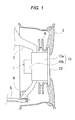
- FIG. 1 A schematic inner configuration of a wheel 2 fitted with an in-wheel motor driving device 1 of this embodiment will be described by reference to Fig. 1 .
- the in-wheel motor driving device 1 is provided at the center of the wheel 2.
- a steering knuckle 3 is fixed to a housing 10 of the in-wheel motor driving device 1.
- the wheel 2 and a brake disc 4 are fixed to an output member 22 of the in-wheel motor driving device 1.
- the steering knuckle 3 is supported on a lower arm 5 via a pivot 6 which is provided at a distal end of the lower arm 5. It should be noted that the steering knuckle 3, the lower arm 5 and the pivot 6 constitute a mechanism for connecting a steering wheel, not shown, with the wheel 2.
- the configuration of the in-wheel motor driving device 1 will be described by reference to Figs. 2 and 3 .
- the in-wheel motor driving device 1 includes the housing 10, a motor 11, an involute speed reduction gear 20 and a control device 40.
- the motor 11 is made up of an inner rotor type motor 11a and an outer rotor type motor 11b which are disposed end to end in the direction of a rotational axis.
- the involute speed reduction gear 20 is an involute speed reduction gear with a small difference in number of teeth and is disposed on an inner side of the inner rotor type motor 11a.
- the motor unit including the motor 11 and the involute speed reduction gear 20 are incorporated in the wheel 2 of the vehicle.
- the housing 10 includes a large-diameter cylindrical housing 10a accommodating the inner rotor type motor 11a and a small-diameter cylindrical housing 10b accommodating the outer rotor type motor 11b which are formed integrally.
- the motor 11 includes a rotor 12 in which a large-diameter rotor 12a and a small-diameter rotor 12b are formed integrally so as to be aligned coaxially end to end with each other in the direction of a rotational axis thereof, that is, a rotor 12 which is formed into a stepped cylindrical shape, a first stator 13 having a cylindrical shape which is disposed so as to face a radially outer side of the large-diameter rotor 12a, and a second stator 14 having a cylindrical shape which is disposed so as to face a radially inner side of the small-diameter rotor 12b.
- the inner rotor type motor 11a is made up of the large-diameter rotor 12a and the first stator 13 and the outer rotor type motor 11b is made up of the small-diameter rotor 12b and the second stator 14.
- the large-diameter rotor 12a and the small-diameter rotor 12b which are both cylindrical, each include, for example, a rotor yoke and a magnet.
- the first stator 13 and the second stator 14 each include a stator core and a coil wound around the stator core.
- the first stator 13 is fixed to an inner circumferential surface of the large-diameter housing 10a.
- the second stator 14 is fixed to a bottom surface of the small-diameter housing 10b.
- the involute speed reduction gear 20 with a small difference in number of teeth which can be made small in size can be disposed on an inner side of the inner rotor type motor 11a, the size in the direction of the rotational axis can be reduced. Further, in the inner rotor type motor 11a, since the first stator 13 is disposed so as to face the radially outer side of the large-diameter rotor 12a, heat generated in the first stator 13 is easily dissipated.
- the outer rotor type motor 11b since the second stator 14 is disposed so as to face the radially inner side of the small-diameter rotor 12b, a torque radius of the small-diameter rotor 12b can be made large, thereby making it possible to ensure a large torque capacity. Because of this, the outer rotor type motor 11b can be made smaller in diameter than the inner rotor type motor 11a, thereby making it possible to ensure a large space within the wheel 2. Consequently, the pivot 5 provided at the distal end of the lower arm 4 which supports the steering knuckle 3 and other components whose illustration is omitted can be disposed within the wheel 2.
- the control device 40 controls an electric current which is supplied to the first stator 13 and the second stator 14 so as to control the rotation of the motor 11.
- an electric current A which is supplied to the motor 11 (the torque of the motor 11) is increased
- threshold serviceable hours H which constitute a service limit where the temperature of the motor 11 reaches a predetermined temperature (for example, 200°) are reduced in an exponential function-like fashion.
- the control device 40 repeats, for example, the following control. Namely, firstly, the electric current A is supplied only to the first stator 13, and the supply of the electric current to the first stator 13 is stopped before the threshold serviceable hours H, which correspond to the electric current A, are reached.
- the electric current A is supplied only to the second stator 14, and the supply of the electric current to the second stator 14 is stopped before the threshold serviceable hours H, which correspond to the electric current A, are reached.
- the control device 40 can supply the electric current (electric power) to the first stator 13 and the second stator 14 simultaneously, allowing a large torque to be exhibited.
- the involute speed reduction gear 20 includes mainly an input member 21, an output member 22, a fixed shaft member 23, a gear shaft 24, a first oscillating member 25, a second oscillating member 26, and a pin supporting member 27.
- the housing 10 supports the input member 21 and the output member 22 directly or indirectly so as to rotate about a common input/output axis Lo.
- the input member 21 is a member which rotates around the input/output axis Lo as the motor 11 is driven.
- the input member 21 has a cylindrical shape and is integrated with a distal inner circumferential portion of the large-diameter rotor 12a.
- a first eccentric portion 21a and a second eccentric portion 21b are formed on an inner circumferential surface of the input member 21.
- the first eccentric portion 21a is an annular portion which has a cylindrical inner surface 211a which is centered on a first eccentric axis La which is an eccentric axis which deviates from the input/output axis Lo.
- the second eccentric portion 21b is an annular portion which has a cylindrical inner surface 211b which is centered on a second eccentric axis Lb that is an eccentric axis which deviates from the input/output axis Lo and which differs from the first eccentric axis La.
- first eccentric portion 21a and the second eccentric portion 21b are formed so as to deviate in opposite directions to each other with respect to the input/output axis Lo.
- the cylindrical inner surface 211a of the first eccentric portion 21a and the cylindrical inner surface 211b of the second eccentric portion 21b are formed at angular intervals of 180 (degrees) so as to lie at equal intervals in a rotational direction about the input/output axis Lo.
- the output member 22 is a member which rotates around the input/output axis Lo as the motor 11 is driven.
- the output member 22 has a disc shape.
- a rotational shaft 22a is supported rotatably on an inner circumference of the gear shaft 24, and an outer circumference of the rotational shaft is connected to the wheel 2 (refer to Fig. 1 ).
- the output member 22 will be described in detail later.
- the fixed shaft member 23 is a fixed member which does not rotate relative to the housing 10 even when the speed reduction gear 20 is driven.
- the fixed shaft member 23 has a cylindrical shape and is integrated with a distal end of the second stator 14.
- the gear shaft 24 is a sun gear on a cylindrical outer circumference of which external teeth 24a which are involute teeth are formed and is integrated with a distal end of the fixed shaft member 23.
- the first oscillating member 25 has an annular shape and has an internal gear 25a having involute teeth and insertion holes 25b, being a planetary gear which is supported rotatably on the cylindrical inner surface 211a of the first eccentric portion 21a on an outer circumferential surface thereof.
- the internal gear 25a is formed on an inner circumferential surface of the first oscillating member 25 and is a gear which can mesh with the external teeth 24a of the gear shaft 24.
- the insertion holes 25b are pin holes that are formed so as to penetrate both end faces of the first oscillating member 25 in the direction of the input/output axis Lo and into which pins 28 which are supported by a pin supporting member 27, which will be described later, are inserted.
- the insertion holes 25b are formed in six locations and are disposed at equal intervals in a circumferential direction of the first oscillating member 25.
- a bore diameter of the insertion holes 25b of the first oscillating member 25 is set so as to be substantially equal to a sum of a diameter of the pin 28 inserted thereinto and a deviating amount of the first oscillating member 25 (a distance at which the input/output axis Lo is spaced apart from the first eccentric axis La).
- the diameter of the pin 28 corresponds to a diameter of the rolling bearing 29.
- the second oscillating member 26 has an annular shape and has an internal gear 26a having involute teeth and insertion holes 26b, being a planetary gear which is supported rotatably on the cylindrical inner surface 211b of the second eccentric portion 21b on an outer circumferential surface thereof.
- the internal gear 26a is formed on an inner circumferential surface of the second oscillating member 26 and is a gear which can mesh with the external teeth 24a of the gear shaft 24.
- the insertion holes 26b are pin holes that are formed so as to penetrate both end faces of the second oscillating member 26 in the direction of the input/output axis Lo, into which the pins 28 which are supported by the pin supporting member 27 are inserted and which fits the pins 28 via the rolling bearing 29.
- the insertion holes 26b are formed in six locations and are disposed at equal intervals in a circumferential direction of the second oscillating member 26.
- An inside diameter of the insertion holes 26b of the second oscillating member 26 is set so as to be substantially equal to a sum of the diameter of the pin 28 inserted thereinto and a deviating amount of the second oscillating member 26 (a distance at which the input/output axis Lo is spaced apart from the second eccentric axis Lb).
- the diameter of the pin 28 corresponds to the diameter of the rolling bearing 29.
- the first oscillating member 25 and the second oscillating member 26 which are made up of the planetary gears of the same type in this way are supported by the first eccentric portion 21a and the second eccentric portion 21b, respectively. Additionally, the cylindrical inner surface 211a of the first eccentric portion 21a and the cylindrical inner surface 211b of the second eccentric portion 21b are formed at angular intervals of 180 (degrees) so as to be disposed at equal intervals in the rotational direction about the input/output axis Lo. Adopting this configuration results in a relation in which the first oscillating member 25 and the second oscillating member 26 are positioned at equal intervals in the circumferential direction of the rotation about the input/output axis Lo.
- first and second eccentric portions 21a, 21b rotate, and the first and second oscillating members 25, 26 oscillate and rotate as the first and second eccentric portions 21a, 21b rotate so.
- Respective rotational or spinning axes (the first eccentric axis La and the second eccentric axis Lb) of the first and second oscillating members 25, 26 revolve around the input/output axis Lo while maintaining their symmetric positions relative to the input/output axis Lo due to the positional relation described above.
- the pin supporting member 27 is a disc-shaped member which is supported by the fixed shaft member 23 via a bearing 30 and is disposed so as to rotate about the input/output axis Lo. This pin supporting member 27 is situated in a direction in which the pins 28 project relative to the first and second oscillating members 25, 26. Additionally, in the pin supporting member 27, an equal number of pin holes to the number of pins 28 are formed so as to be connected with end portions of the pins 28 which pass through the insertion holes 25b, 26b of the first and second oscillating members 25, 26 through press or loose fitting. By doing so, the pin supporting member 27 supports the six pins 28 which are fixed to the output member 22 and rotates at the same rotational speed as that of the output member 22 as the output member 22 rotates.
- the output member 22 is situated in the direction in which the pins 28 project relative to the first and second oscillating members 25, 26.
- an equal number of pin holes to the number of pins 28 are formed so as to be connected with the end portions of the pins 28 which pass through the insertion holes 25b, 26b of the first and second oscillating members 25, 26 through press or loose fitting.
- the output member 22 is connected to the first and second oscillating members 25, 26 so as to be linked with the rotational component of the oscillation and rotation of the first and second oscillating members 25, 26.
- the operation of the involute speed reduction gear 20 will be described. Firstly, when the motor 11 is actuated, the first eccentric portion 21a and the second eccentric portion 21b of the input member 21 which is integrated with the large-diameter rotor 12a of the motor 11 rotate. Then, the first oscillating member 25 which is supported on an inner circumferential side of the first eccentric portion 21a oscillates and rotates as the first eccentric portion 21a rotates. Similarly, the second oscillating member 26 which is supported on an inner circumferential side of the second eccentric portion 21b oscillates and rotates as the second eccentric portion 21b rotates. As they do so, the first and second oscillating members 25, 26 revolve about the input/output axis Lo at a revolving speed equal to the rotational speed of the input member 21 as the input member 21 rotates.
- the internal gears 25a, 26a of the first and second oscillating members 25, 26 individually mesh with the external teeth 24a of the gear shaft 24 only at part of the circumferences thereof. Additionally, the gear shaft 24 is fixed to the fixed shaft member 23. Therefore, the first and second oscillating members 25, 26 rotate on the first and second eccentric axes La, Lb, respectively, at a rotational speed based on a difference in the number of teeth between the internal gears 25a, 26a and the external teeth 24a of the gear shaft 24 while revolving. The rotational directions then become an opposite direction to the rotational direction of the input member 21 (in case the input member 21 rotates in a clockwise direction, the internal gears 25a, 26a rotate in a counterclockwise direction).
- the pins 28 are inserted in the respective insertion holes 25b, 26b of the first and second oscillating members 25, 26. Then, outer circumferential surfaces of the rolling bearings 29 which are fitted on the pins 28 are brought into abutment with the corresponding inner circumferential surfaces of the insertion holes 25b, 26b only at part of circumferences of the rolling bearings 29 whereby the driving force is transmitted thereto.
- the first and second oscillating members 25, 26 oscillate and rotate, the rotational component is transmitted to the pins 28.
- the output member 22 rotates at the rotational speed at which the first and second oscillating members 25, 26 rotate on their own axes.
- the output member 22 takes out the rotational component from the oscillation and rotation of the first and second oscillating members 25, 26 via the pins 28 and the rolling bearings 29, and the rotation inputted from the input member 21 is decelerated to be outputted from the output member 22.
- the motor unit of the in-wheel motor driving device 1 includes the first stator 13 and the second stator 14 and substantially has the two motors 11a, 11b.
- the rotor 12 (the large-diameter rotor 12a, the small-diameter rotor 12b) is shared commonly by the two motors 11a, 11b, and therefore, the respective outputs of the two motors 11a, 11b are outputted from the same rotor 12. Then, by using the outputs of the two motors 11a, 11b and the servicing hours separately, heat generated from the first stator 13 and the second stator 14 can be suppressed.
- the first stator 13 is disposed so as to face the radially outer side of the large-diameter rotor 12a, heat generated in the first stator 13 is easily dissipated. Additionally, by disposing the first stator 13 on the radially outer side of the rotor 12, the space is defined on the radially inner side of the large-diameter rotor 12a.
- the involute speed reduction gear 20 is disposed in the space defined on the radially inner side of the first stator 13 and on the radially inner side of the large-diameter rotor 12a. Namely, the first stator 13 and the involute speed reduction gear 20 are disposed in the same position in the axial direction.
- the motor unit can be accommodated within the wheel 2 in an ensured fashion.
- the small-diameter rotor 12b has a large diameter. Because of this, the diameter of the portion of the small-diameter rotor 12b which faces the second stator 14 in the radial direction should be as large as possible.
- the involute speed reduction gear 20 is disposed on the radially inner side of the large-diameter rotor 12a and on the radially inner side of the first stator. Because of this, the involute speed reduction gear 20 does not have to be disposed on the radially inner side of the portion of the small-diameter rotor 12b which faces the second stator 14 in the radial direction.
- the more the diameter of the small-diameter rotor 12b is increased to ensure a large torque capacity the more space can be defined on the radially inner side of the rotor 12. Then, the second stator 14 is disposed in the space. Consequently, the torque capacity by the second stator 14 can be made large, and the radial size of the in-wheel motor driving device 1 can be made small.
- the outside diameter of the inner rotor type motor having the first stator 13 becomes the outside diameter of the first stator 13.
- the outside diameter of the outer rotor type motor having the second stator 14 becomes the outside diameter of the portion of the small-diameter rotor 12b. Namely, even though the diameter of the small-diameter rotor 12b with which the required torque capacity is ensured is ensured, the outer rotor type motor having the second stator 14 can define the space on the radially outer side of the motor within the wheel 2.
- the motor unit and the connecting mechanism can be disposed within the wheel 2 while the motor unit is allowed to include the two motors 11a, 11b, and both the two motors 11a, 11b can ensure their required torque capacities.
- the diameter of the inner rotor type motor 11a is made large and the diameter of the outer rotor type motor 11b is made small, the diameters of the inner rotor type motor 11a and the outer rotor type motor 11b may be made the same.
- the invention can also be applied to speed reduction gears which are configured differently from the involute speed reduction gear 20.
- the small in-wheel motor driving device that has the large torque capacity and which can suppress the generation of heat.
Landscapes
- Engineering & Computer Science (AREA)
- Mechanical Engineering (AREA)
- Transportation (AREA)
- Combustion & Propulsion (AREA)
- Chemical & Material Sciences (AREA)
- Power Engineering (AREA)
- General Engineering & Computer Science (AREA)
- Automation & Control Theory (AREA)
- Life Sciences & Earth Sciences (AREA)
- Sustainable Energy (AREA)
- Sustainable Development (AREA)
- Electromagnetism (AREA)
- Physics & Mathematics (AREA)
- Arrangement Or Mounting Of Propulsion Units For Vehicles (AREA)
- Connection Of Motors, Electrical Generators, Mechanical Devices, And The Like (AREA)
- Retarders (AREA)
- Electric Propulsion And Braking For Vehicles (AREA)
- Hybrid Electric Vehicles (AREA)
- Power Steering Mechanism (AREA)
- Braking Arrangements (AREA)
Abstract
Description
- The present invention relates to an in-wheel motor driving device incorporated in a wheel of a vehicle and rotates the wheel.
- For example,
Patent Literature 1 discloses an in-wheel motor driving device including a motor, a cycloid speed reduction gear interposed between the motor and a wheel bearing, a control device for controlling the driving of the motor and a temperature sensor mounted on the motor. When a vehicle equipped with an in-wheel motor driving device runs at low speeds, a large torque is needed, and when the motor and the speed reduction gear are overloaded, the temperature of the motor or the like tends to rise excessively. Then, the control device limits the driving electric current of the motor according to information on a temperature measured by the temperature sensor so as to prevent an excessive increase in the temperature of the motor or the like. - In addition,
Patent Literature 2 discloses an inverter device for driving a motor which has two rotors, having different outputs and disposed on the same output shaft, and two stators. In this inverter device, individual inverter circuits are provided exclusively for the rotors. Then, the inverter circuit for one of the two rotors which has a smaller output is controlled with a high frequency, while the inverter circuit of the other rotor which has a larger output is controlled with a low frequency, whereby the heat value of the motor is suppressed. - Additionally,
Patent Literature 3 discloses a motor control device for controlling the driving of two motors. In this motor control device, a load distribution ratio at which the total loss of the two motors becomes the least is determined based on the required outputs and detected temperatures of the motors to control the driving of the motors, whereby the increase in the temperatures of the two motors is suppressed. -
- Patent Literature 1:
JP-A-2008-168790 - Patent Literature 2:
JP-A-6-327294 - Patent Literature 3:
JP-A-6-284788 - A pivot which is provided at a distal end of a lower arm which supports a steering knuckle and other components are disposed within a wheel of a vehicle. Because of this, a space where to dispose an in-wheel motor driving device is limited, and hence, the in-wheel motor driving device needs to be made small in size. In addition, when a vehicle equipped with an in-wheel motor driving device runs at low speeds, the in-wheel motor driving device needs to exhibit a large torque, and the heat generation from the in-wheel motor driving device needs to be suppressed.
- All the inventions described in
Patent Literatures 1 to 3 can suppress the heat generation from the motors. However, when it is made small in size, the cycloid speed reduction gear cannot bear a large torque. Because of this, with the in-wheel motor driving device including the cycloid speed reduction gear which is described inPatent Literature 1, there is a limitation on types of vehicles to which it can be applied. Additionally, the in-wheel motor driving device described inPatent Literature 2 in which the speed reduction gear is fitted on the motor is enlarged in the direction of the rotational axis. In addition, the in-wheel motor driving device described inPatent Literature 3 in which the speed reduction gear is fitted on each of the two separate motors is enlarged further. Because of this, it is difficult to accommodate the enlarged motor within the wheel where the space where to accommodate the motor is limited. - The invention has been made in view of these situations, and an object thereof is to provide a small in-wheel motor driving device that has a large torque capacity and which can suppress the generation of heat.
- According to the invention, there is provided an in-wheel motor driving device comprising a motor unit which is incorporated within a wheel of a vehicle and which includes a motor and a speed reduction gear, and a control device which is configured to control driving of the motor, wherein a cylindrical rotor, a cylindrical first stator which is disposed so as to face a radially outer side of the rotor, and a cylindrical second stator which is disposed so as to face a radially inner side of the rotor and which is disposed so as to be deviated in the direction of a rotational axis relative to the first stator are included, and the speed reduction gear is disposed on the radially inner side of the rotor and on a radially inner side of the first stator.
- A mechanism connecting a steering wheel with the wheel of the vehicle should be disposed on the radially outer side of the rotor and a radially outer side of the second stator within the wheel of the vehicle.
- The speed reduction gear should include an involute gear from an outer circumferential side of which a rotational force of the motor is inputted and from an inner circumferential side of which the rotational force of the motor is outputted.
- The control device should control the driving of the motor by switching alternately an electric power supply to the first stator and an electric power supply to the second stator. Advantage of the Invention
- According to the invention, the motor unit includes the first stator and the second stator. Namely, the motor unit substantially has two motors. However, the rotor is shared by the two motors. Consequently, outputs of the two motors are outputted from the single common rotor. Additionally, having the two motors as the common rotor enables the outputs and serving hours of the two motors to be used separately, thereby making it possible to suppress the heat generation from the first stator and the second stator.
- Further, according to the invention, since the first stator is disposed so as to face the radially outer side of the rotor, heat generated in the first stator is easily dissipated. In addition, a space is defined on the radially inner side of the rotor by disposing the first stator on the radially outer side of the rotor. The speed reduction gear is disposed in the space which is defined on the radially inner side of the first stator and on the radially inner side of the rotor. Namely, the first stator and the speed reduction gear are disposed in the same axial position. By adopting this arrangement, the in-wheel motor driving device can be made small in the axial direction while improving the heat dissipating properties of the first stator. Here, the axial length of the wheel cannot be ensured so long. Namely, by adopting the configuration described above, the motor unit can be accommodated within the wheel in an ensured fashion.
- Here, with a view to ensuring a large torque capacity, it is desired that the rotor has a large diameter. Because of this, the diameter of a portion of the rotor which faces the second stator in the radial direction should be as large as possible. Additionally, as has been described above, the speed reduction gear has already been disposed on the radially inner side of the rotor and on the radially inner side of the first stator. Because of this, the speed reduction gear does not have to be disposed on a radially inner side of the portion of the rotor which faces the second stator in the radial direction. Namely, the more the diameter of the rotor is increased to ensure a large torque capacity, the more space can be defined on the radially inner side of the rotor. Then, the second stator can be disposed in the space. Consequently, the torque capacity by the second stator can be made large, and the radial size of the in-wheel motor driving device can be made small.
- A mechanism which connects the steering wheel with the wheel needs to be disposed within the steered wheel. Namely, a space where to enable the mechanism to be disposed within the wheel needs to be ensured. In the in-wheel motor, since the motor unit is disposed within the wheel, it is not easy for the mechanism to be disposed so.
- Here, according to the invention, the outside diameter of the inner rotor type motor having the first stator becomes the outside diameter of the first stator. On the other hand, the outside diameter of the outer rotor type motor having the second stator becomes the outside diameter of the portion of the rotor. Namely, even though the diameter of the rotor with which the required torque capacity is ensured is ensured, the outer rotor type motor having the second stator can define the space on the radially outer side of the motor within the wheel. Then, by disposing the mechanism which connects the steering wheel with the wheel in the space, the motor unit and the connecting mechanism can be disposed within the wheel while the motor unit is allowed to include the two motors, and both the two motors can ensure their required torque capacities.
- According to the invention, since the involute speed reduction gear, which can be made small in size, can be disposed on the inner side of the rotor of the inner rotor type motor, the size in the direction of the rotational axis can be reduced.
- According to the invention, while one of the inner rotor type motor and the outer rotor type motor is being used, the other can be kept stopped for rest, and therefore, the heat generation from the motors can be suppressed.
-
-
Fig. 1 is a partial sectional view showing a schematic inner configuration of a wheel fitted with an in-wheel motor driving device of this embodiment. -
Fig. 2 is a sectional view showing the in-wheel motor driving device shown inFig. 1 . -
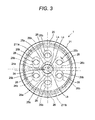
Fig. 3 is a view of a main part of the in-wheel motor driving device resulting when seen in the direction of the line A-A inFig. 2 . -
Fig. 4 is a diagram showing a relation between an electric current A supplied to a motor (the torque of the motor) and threshold serviceable hours H which constitute a service limit where the temperature of the motor reaches a predetermined temperature. - A schematic inner configuration of a
wheel 2 fitted with an in-wheelmotor driving device 1 of this embodiment will be described by reference toFig. 1 . The in-wheelmotor driving device 1 is provided at the center of thewheel 2. Asteering knuckle 3 is fixed to ahousing 10 of the in-wheelmotor driving device 1. Thewheel 2 and abrake disc 4 are fixed to anoutput member 22 of the in-wheelmotor driving device 1. Thesteering knuckle 3 is supported on alower arm 5 via apivot 6 which is provided at a distal end of thelower arm 5. It should be noted that thesteering knuckle 3, thelower arm 5 and thepivot 6 constitute a mechanism for connecting a steering wheel, not shown, with thewheel 2. - The configuration of the in-wheel
motor driving device 1 will be described by reference toFigs. 2 and3 . The in-wheelmotor driving device 1 includes thehousing 10, amotor 11, an involutespeed reduction gear 20 and acontrol device 40. Themotor 11 is made up of an innerrotor type motor 11a and an outerrotor type motor 11b which are disposed end to end in the direction of a rotational axis. The involutespeed reduction gear 20 is an involute speed reduction gear with a small difference in number of teeth and is disposed on an inner side of the innerrotor type motor 11a. The motor unit including themotor 11 and the involutespeed reduction gear 20 are incorporated in thewheel 2 of the vehicle. Although it will be described in detail later, the rotational driving force of either or both of the innerrotor type motor 11a and the outerrotor type motor 11b is transmitted to the involutespeed reduction gear 20 for reduction in speed. - The
housing 10 includes a large-diametercylindrical housing 10a accommodating the innerrotor type motor 11a and a small-diametercylindrical housing 10b accommodating the outerrotor type motor 11b which are formed integrally. - The
motor 11 includes arotor 12 in which a large-diameter rotor 12a and a small-diameter rotor 12b are formed integrally so as to be aligned coaxially end to end with each other in the direction of a rotational axis thereof, that is, arotor 12 which is formed into a stepped cylindrical shape, afirst stator 13 having a cylindrical shape which is disposed so as to face a radially outer side of the large-diameter rotor 12a, and asecond stator 14 having a cylindrical shape which is disposed so as to face a radially inner side of the small-diameter rotor 12b. Namely, the innerrotor type motor 11a is made up of the large-diameter rotor 12a and thefirst stator 13, and the outerrotor type motor 11b is made up of the small-diameter rotor 12b and thesecond stator 14. - The large-
diameter rotor 12a and the small-diameter rotor 12b, which are both cylindrical, each include, for example, a rotor yoke and a magnet. In addition, thefirst stator 13 and thesecond stator 14 each include a stator core and a coil wound around the stator core. Thefirst stator 13 is fixed to an inner circumferential surface of the large-diameter housing 10a. Thesecond stator 14 is fixed to a bottom surface of the small-diameter housing 10b. - According to this configuration, since the involute
speed reduction gear 20 with a small difference in number of teeth which can be made small in size can be disposed on an inner side of the innerrotor type motor 11a, the size in the direction of the rotational axis can be reduced. Further, in the innerrotor type motor 11a, since thefirst stator 13 is disposed so as to face the radially outer side of the large-diameter rotor 12a, heat generated in thefirst stator 13 is easily dissipated. On the other hand, in the outerrotor type motor 11b, since thesecond stator 14 is disposed so as to face the radially inner side of the small-diameter rotor 12b, a torque radius of the small-diameter rotor 12b can be made large, thereby making it possible to ensure a large torque capacity. Because of this, the outerrotor type motor 11b can be made smaller in diameter than the innerrotor type motor 11a, thereby making it possible to ensure a large space within thewheel 2. Consequently, thepivot 5 provided at the distal end of thelower arm 4 which supports thesteering knuckle 3 and other components whose illustration is omitted can be disposed within thewheel 2. - The
control device 40 controls an electric current which is supplied to thefirst stator 13 and thesecond stator 14 so as to control the rotation of themotor 11. Here, as shown inFig. 4 , when an electric current A which is supplied to the motor 11 (the torque of the motor 11) is increased, threshold serviceable hours H which constitute a service limit where the temperature of themotor 11 reaches a predetermined temperature (for example, 200°) are reduced in an exponential function-like fashion. Then, thecontrol device 40 repeats, for example, the following control. Namely, firstly, the electric current A is supplied only to thefirst stator 13, and the supply of the electric current to thefirst stator 13 is stopped before the threshold serviceable hours H, which correspond to the electric current A, are reached. Next, the electric current A is supplied only to thesecond stator 14, and the supply of the electric current to thesecond stator 14 is stopped before the threshold serviceable hours H, which correspond to the electric current A, are reached. In this way, by switching alternately the electric currents (electric power) supplied to thefirst stator 13 and thesecond stator 14, since when one of the innerrotor type motor 11a and the outerrotor type motor 11b is being used, the other can be stopped for rest, the heat generation from themotor 11 can be suppressed. In addition, thecontrol device 40 can supply the electric current (electric power) to thefirst stator 13 and thesecond stator 14 simultaneously, allowing a large torque to be exhibited. - The involute
speed reduction gear 20 includes mainly aninput member 21, anoutput member 22, a fixedshaft member 23, agear shaft 24, a first oscillatingmember 25, a second oscillatingmember 26, and apin supporting member 27. Thehousing 10 supports theinput member 21 and theoutput member 22 directly or indirectly so as to rotate about a common input/output axis Lo. - The
input member 21 is a member which rotates around the input/output axis Lo as themotor 11 is driven. Theinput member 21 has a cylindrical shape and is integrated with a distal inner circumferential portion of the large-diameter rotor 12a. A firsteccentric portion 21a and a secondeccentric portion 21b are formed on an inner circumferential surface of theinput member 21. The firsteccentric portion 21a is an annular portion which has a cylindricalinner surface 211a which is centered on a first eccentric axis La which is an eccentric axis which deviates from the input/output axis Lo. The secondeccentric portion 21b is an annular portion which has a cylindricalinner surface 211b which is centered on a second eccentric axis Lb that is an eccentric axis which deviates from the input/output axis Lo and which differs from the first eccentric axis La. - In addition, the first
eccentric portion 21a and the secondeccentric portion 21b are formed so as to deviate in opposite directions to each other with respect to the input/output axis Lo. By doing so, the cylindricalinner surface 211a of the firsteccentric portion 21a and the cylindricalinner surface 211b of the secondeccentric portion 21b are formed at angular intervals of 180 (degrees) so as to lie at equal intervals in a rotational direction about the input/output axis Lo. - The
output member 22 is a member which rotates around the input/output axis Lo as themotor 11 is driven. Theoutput member 22 has a disc shape. Arotational shaft 22a is supported rotatably on an inner circumference of thegear shaft 24, and an outer circumference of the rotational shaft is connected to the wheel 2 (refer toFig. 1 ). Theoutput member 22 will be described in detail later. The fixedshaft member 23 is a fixed member which does not rotate relative to thehousing 10 even when thespeed reduction gear 20 is driven. The fixedshaft member 23 has a cylindrical shape and is integrated with a distal end of thesecond stator 14. Thegear shaft 24 is a sun gear on a cylindrical outer circumference of whichexternal teeth 24a which are involute teeth are formed and is integrated with a distal end of the fixedshaft member 23. - The first oscillating
member 25 has an annular shape and has aninternal gear 25a having involute teeth andinsertion holes 25b, being a planetary gear which is supported rotatably on the cylindricalinner surface 211a of the firsteccentric portion 21a on an outer circumferential surface thereof. Theinternal gear 25a is formed on an inner circumferential surface of the first oscillatingmember 25 and is a gear which can mesh with theexternal teeth 24a of thegear shaft 24. By adopting this configuration, the first oscillatingmember 25 oscillates and rotates relative to the input/output axis Lo in association with rotation of theinput member 21 with theinternal gear 25a caused to mesh with theexternal teeth 24a of thegear shaft 24. - The insertion holes 25b are pin holes that are formed so as to penetrate both end faces of the first oscillating
member 25 in the direction of the input/output axis Lo and into which pins 28 which are supported by apin supporting member 27, which will be described later, are inserted. In this embodiment, as shown inFig. 3 , the insertion holes 25b are formed in six locations and are disposed at equal intervals in a circumferential direction of the first oscillatingmember 25. A bore diameter of the insertion holes 25b of the first oscillatingmember 25 is set so as to be substantially equal to a sum of a diameter of thepin 28 inserted thereinto and a deviating amount of the first oscillating member 25 (a distance at which the input/output axis Lo is spaced apart from the first eccentric axis La). In this embodiment, however, since a rollingbearing 29 is fitted on thepin 28, the diameter of thepin 28 corresponds to a diameter of the rollingbearing 29. - The second oscillating
member 26 has an annular shape and has aninternal gear 26a having involute teeth andinsertion holes 26b, being a planetary gear which is supported rotatably on the cylindricalinner surface 211b of the secondeccentric portion 21b on an outer circumferential surface thereof. Theinternal gear 26a is formed on an inner circumferential surface of the second oscillatingmember 26 and is a gear which can mesh with theexternal teeth 24a of thegear shaft 24. By adopting this configuration, the second oscillatingmember 26 oscillates and rotates relative to the input/output axis Lo in association with rotation of theinput member 21 with theinternal gear 26a caused to mesh with theexternal teeth 24a of thegear shaft 24. - The insertion holes 26b are pin holes that are formed so as to penetrate both end faces of the second oscillating
member 26 in the direction of the input/output axis Lo, into which thepins 28 which are supported by thepin supporting member 27 are inserted and which fits thepins 28 via the rollingbearing 29. In this embodiment, as shown inFig. 3 , the insertion holes 26b are formed in six locations and are disposed at equal intervals in a circumferential direction of the second oscillatingmember 26. An inside diameter of the insertion holes 26b of the second oscillatingmember 26 is set so as to be substantially equal to a sum of the diameter of thepin 28 inserted thereinto and a deviating amount of the second oscillating member 26 (a distance at which the input/output axis Lo is spaced apart from the second eccentric axis Lb). In this embodiment, however, since the rollingbearing 29 is fitted on thepin 28, the diameter of thepin 28 corresponds to the diameter of the rollingbearing 29. - The first oscillating
member 25 and the second oscillatingmember 26 which are made up of the planetary gears of the same type in this way are supported by the firsteccentric portion 21a and the secondeccentric portion 21b, respectively. Additionally, the cylindricalinner surface 211a of the firsteccentric portion 21a and the cylindricalinner surface 211b of the secondeccentric portion 21b are formed at angular intervals of 180 (degrees) so as to be disposed at equal intervals in the rotational direction about the input/output axis Lo. Adopting this configuration results in a relation in which the first oscillatingmember 25 and the second oscillatingmember 26 are positioned at equal intervals in the circumferential direction of the rotation about the input/output axis Lo. Here, as theinput member 21 rotates, the first and secondeccentric portions members eccentric portions members - The
pin supporting member 27 is a disc-shaped member which is supported by the fixedshaft member 23 via abearing 30 and is disposed so as to rotate about the input/output axis Lo. Thispin supporting member 27 is situated in a direction in which thepins 28 project relative to the first and second oscillatingmembers pin supporting member 27, an equal number of pin holes to the number ofpins 28 are formed so as to be connected with end portions of thepins 28 which pass through theinsertion holes members pin supporting member 27 supports the sixpins 28 which are fixed to theoutput member 22 and rotates at the same rotational speed as that of theoutput member 22 as theoutput member 22 rotates. - The
output member 22 is situated in the direction in which thepins 28 project relative to the first and second oscillatingmembers output member 22, an equal number of pin holes to the number ofpins 28 are formed so as to be connected with the end portions of thepins 28 which pass through theinsertion holes members members input member 21, the driving force is transmitted from inner circumferential surfaces of therespective insertion holes members pins 28 and the rollingbearings 29 to theoutput member 22. As this occurs, due to the dimensional relation of the outside diameter of the rollingbearing 29 with theindividual insertion holes members output member 22 is connected to the first and second oscillatingmembers members - Next, the operation of the involute
speed reduction gear 20 will be described. Firstly, when themotor 11 is actuated, the firsteccentric portion 21a and the secondeccentric portion 21b of theinput member 21 which is integrated with the large-diameter rotor 12a of themotor 11 rotate. Then, the first oscillatingmember 25 which is supported on an inner circumferential side of the firsteccentric portion 21a oscillates and rotates as the firsteccentric portion 21a rotates. Similarly, the second oscillatingmember 26 which is supported on an inner circumferential side of the secondeccentric portion 21b oscillates and rotates as the secondeccentric portion 21b rotates. As they do so, the first and second oscillatingmembers input member 21 as theinput member 21 rotates. - Here, the
internal gears members external teeth 24a of thegear shaft 24 only at part of the circumferences thereof. Additionally, thegear shaft 24 is fixed to the fixedshaft member 23. Therefore, the first and second oscillatingmembers internal gears external teeth 24a of thegear shaft 24 while revolving. The rotational directions then become an opposite direction to the rotational direction of the input member 21 (in case theinput member 21 rotates in a clockwise direction, theinternal gears - Here, the
pins 28 are inserted in therespective insertion holes members bearings 29 which are fitted on thepins 28 are brought into abutment with the corresponding inner circumferential surfaces of theinsertion holes bearings 29 whereby the driving force is transmitted thereto. By doing so, when the first and second oscillatingmembers pins 28. Then, theoutput member 22 rotates at the rotational speed at which the first and second oscillatingmembers output member 22 takes out the rotational component from the oscillation and rotation of the first and second oscillatingmembers pins 28 and the rollingbearings 29, and the rotation inputted from theinput member 21 is decelerated to be outputted from theoutput member 22. - The motor unit of the in-wheel
motor driving device 1 includes thefirst stator 13 and thesecond stator 14 and substantially has the twomotors diameter rotor 12a, the small-diameter rotor 12b) is shared commonly by the twomotors motors same rotor 12. Then, by using the outputs of the twomotors first stator 13 and thesecond stator 14 can be suppressed. - Further, since the
first stator 13 is disposed so as to face the radially outer side of the large-diameter rotor 12a, heat generated in thefirst stator 13 is easily dissipated. Additionally, by disposing thefirst stator 13 on the radially outer side of therotor 12, the space is defined on the radially inner side of the large-diameter rotor 12a. The involutespeed reduction gear 20 is disposed in the space defined on the radially inner side of thefirst stator 13 and on the radially inner side of the large-diameter rotor 12a. Namely, thefirst stator 13 and the involutespeed reduction gear 20 are disposed in the same position in the axial direction. By disposing thefirst stator 13 and the involutespeed reduction gear 20 in the way described above, a reduction in size of the in-wheelmotor driving device 1 can be realized while improving the heat dissipating properties of thefirst stator 13. Here, the axial length of thewheel 2 cannot be made so long. Namely, by adopting the configuration that has been described heretofore, the motor unit can be accommodated within thewheel 2 in an ensured fashion. - In addition, with a view to ensuring a large torque capacity, it is desired that the small-
diameter rotor 12b has a large diameter. Because of this, the diameter of the portion of the small-diameter rotor 12b which faces thesecond stator 14 in the radial direction should be as large as possible. As described above, the involutespeed reduction gear 20 is disposed on the radially inner side of the large-diameter rotor 12a and on the radially inner side of the first stator. Because of this, the involutespeed reduction gear 20 does not have to be disposed on the radially inner side of the portion of the small-diameter rotor 12b which faces thesecond stator 14 in the radial direction. Namely, the more the diameter of the small-diameter rotor 12b is increased to ensure a large torque capacity, the more space can be defined on the radially inner side of therotor 12. Then, thesecond stator 14 is disposed in the space. Consequently, the torque capacity by thesecond stator 14 can be made large, and the radial size of the in-wheelmotor driving device 1 can be made small. - In addition, the outside diameter of the inner rotor type motor having the
first stator 13 becomes the outside diameter of thefirst stator 13. On the other hand, the outside diameter of the outer rotor type motor having thesecond stator 14 becomes the outside diameter of the portion of the small-diameter rotor 12b. Namely, even though the diameter of the small-diameter rotor 12b with which the required torque capacity is ensured is ensured, the outer rotor type motor having thesecond stator 14 can define the space on the radially outer side of the motor within thewheel 2. Then, by disposing the mechanism which connects the steering wheel with thewheel 2 in the space, the motor unit and the connecting mechanism can be disposed within thewheel 2 while the motor unit is allowed to include the twomotors motors - While the diameter of the inner
rotor type motor 11a is made large and the diameter of the outerrotor type motor 11b is made small, the diameters of the innerrotor type motor 11a and the outerrotor type motor 11b may be made the same. In addition, the invention can also be applied to speed reduction gears which are configured differently from the involutespeed reduction gear 20. - According to the invention, it is possible to provide the small in-wheel motor driving device that has the large torque capacity and which can suppress the generation of heat.
-
- 1:
- in-wheel motor driving device
- 2:
- wheel
- 3:
- steering knuckle
- 5:
- lower arm
- 6:
- pivot
- 10, 10a, 10b:
- housing
- 11:
-
motor 11 - 11a:
- inner rotor type motor
- 11b:
- outer rotor type motor
- 12:
- rotor
- 12a:
- large-diameter rotor
- 12b:
- small-diameter rotor
- 13:
- first stator
- 14:
- second stator
- 20:
- involute speed reduction gear
- 21:
- input member
- 22:
- output member
- 23:
- fixed shaft member
- 24:
- gear shaft
- 25:
- first oscillating member
- 26:
- second oscillating member
- 27:
- pin supporting member
- 40:
- control device
Claims (4)
- An in-wheel motor driving device comprising:a motor unit which is incorporated within a wheel of a vehicle and which includes a motor and a speed reduction gear; anda control device which is configured to control driving of the motor, whereinthe motor includes:a cylindrical rotor;a cylindrical first stator which is disposed so as to face a radially outer side of the rotor; anda cylindrical second stator which is disposed so as to face a radially inner side of the rotor and which is disposed so as to be deviated in a direction of a rotational axis relative to the first stator, andthe speed reduction gear is disposed on the radially inner side of the rotor and on a radially inner side of the first stator.
- The in-wheel motor driving device according to Claim 1, wherein
a mechanism connecting a steering wheel with the wheel of the vehicle is disposed on the radially outer side of the rotor and a radially outer side of the second stator within the wheel of the vehicle. - The in-wheel motor driving device according to Claim 1 or 2, wherein
the speed reduction gear includes an involute gear from an outer circumferential side of which a rotational force of the motor is inputted and from an inner circumferential side of which the rotational force of the motor is outputted. - The in-wheel motor driving device according to any of Claims 1 to 3, wherein
the control device controls the driving of the motor by switching alternately an electric power supply to the first stator and an electric power supply to the second stator.
Applications Claiming Priority (6)
| Application Number | Priority Date | Filing Date | Title |
|---|---|---|---|
| JP2011003349 | 2011-01-11 | ||
| JP2011032206 | 2011-02-17 | ||
| JP2011073852A JP5741128B2 (en) | 2011-03-30 | 2011-03-30 | In-wheel motor drive device |
| JP2011256577 | 2011-11-24 | ||
| JP2011280033A JP2013129311A (en) | 2011-02-17 | 2011-12-21 | Motor drive force transmission device |
| PCT/JP2012/050384 WO2012096309A1 (en) | 2011-01-11 | 2012-01-11 | In-wheel motor driving device |
Publications (2)
| Publication Number | Publication Date |
|---|---|
| EP2664487A1 true EP2664487A1 (en) | 2013-11-20 |
| EP2664487A4 EP2664487A4 (en) | 2018-01-24 |
Family
ID=49098406
Family Applications (3)
| Application Number | Title | Priority Date | Filing Date |
|---|---|---|---|
| EP12734769.8A Withdrawn EP2664487A4 (en) | 2011-01-11 | 2012-01-11 | In-wheel motor driving device |
| EP12733963.8A Withdrawn EP2664486A1 (en) | 2011-01-11 | 2012-01-11 | Motor drive force transmission device |
| EP12734585.8A Withdrawn EP2665160A1 (en) | 2011-01-11 | 2012-01-11 | Device for transmitting driving force of motors |
Family Applications After (2)
| Application Number | Title | Priority Date | Filing Date |
|---|---|---|---|
| EP12733963.8A Withdrawn EP2664486A1 (en) | 2011-01-11 | 2012-01-11 | Motor drive force transmission device |
| EP12734585.8A Withdrawn EP2665160A1 (en) | 2011-01-11 | 2012-01-11 | Device for transmitting driving force of motors |
Country Status (4)
| Country | Link |
|---|---|
| US (3) | US9080659B2 (en) |
| EP (3) | EP2664487A4 (en) |
| CN (3) | CN103299516A (en) |
| WO (3) | WO2012096308A1 (en) |
Cited By (1)
| Publication number | Priority date | Publication date | Assignee | Title |
|---|---|---|---|---|
| CN111867866A (en) * | 2018-03-20 | 2020-10-30 | 马自达汽车株式会社 | vehicle drive |
Families Citing this family (28)
| Publication number | Priority date | Publication date | Assignee | Title |
|---|---|---|---|---|
| US8936120B2 (en) * | 2011-12-29 | 2015-01-20 | Kawasaki Jukogyo Kabushiki Kaisha | Utility vehicle having a front electric motor |
| JP5803892B2 (en) * | 2012-12-18 | 2015-11-04 | トヨタ自動車株式会社 | Control device for hybrid vehicle |
| JP6315362B2 (en) * | 2013-03-06 | 2018-04-25 | 合同会社IP Bridge1号 | Electromechanical device, and moving body and robot including the same |
| CN104052189A (en) * | 2013-11-26 | 2014-09-17 | 马力 | Rotor structure of differential motor for electric vehicle |
| CN103791057A (en) * | 2014-02-11 | 2014-05-14 | 安宏亮 | Eccentric wheel limited slip differential |
| US20150288249A1 (en) * | 2014-04-03 | 2015-10-08 | Schaeffler Technologies AG & Co. KG | Eccentric motor |
| JP2016151347A (en) * | 2015-02-19 | 2016-08-22 | Ntn株式会社 | Twin-motor vehicle driving device |
| WO2016172285A1 (en) * | 2015-04-24 | 2016-10-27 | Sri International | Drives with partial cycloid teeth profile |
| US10197141B2 (en) | 2015-11-03 | 2019-02-05 | Metso Flow Control Usa Inc. | Electric actuator with a fail-safe mode of operation |
| JP6599220B2 (en) * | 2015-12-01 | 2019-10-30 | 日本電産シンポ株式会社 | Reducer with electric motor |
| CN105966237B (en) * | 2015-12-31 | 2018-08-14 | 比亚迪股份有限公司 | Vehicle and drive axle assemblies for vehicle |
| CN105966221B (en) * | 2015-12-31 | 2018-05-08 | 比亚迪股份有限公司 | Vehicle and the drive axle assemblies for vehicle |
| KR20170085308A (en) * | 2016-01-14 | 2017-07-24 | 엘지이노텍 주식회사 | Rotor plate, rotor core assembly, motor and vehicle having the same |
| DE102016112426A1 (en) * | 2016-07-06 | 2018-01-11 | Getrag Getriebe- Und Zahnradfabrik Hermann Hagenmeyer Gmbh & Cie Kg | Electric motor assembly and method for mounting an electric motor assembly |
| CN106838202B (en) * | 2017-04-02 | 2024-07-23 | 凌子龙 | Limited slip differential |
| JP7183568B2 (en) * | 2018-05-10 | 2022-12-06 | 日本電産トーソク株式会社 | electric actuator |
| CN108980283B (en) * | 2018-08-13 | 2019-11-05 | 大连碧蓝节能环保科技有限公司 | Bore tooth mechanical differential |
| JP7230451B2 (en) * | 2018-11-19 | 2023-03-01 | トヨタ自動車株式会社 | Layout structure of front space of hybrid vehicle |
| JP7181108B2 (en) * | 2019-01-31 | 2022-11-30 | 日立Astemo株式会社 | WHEEL DRIVE AND ELECTRIC VEHICLE INCLUDING THE SAME |
| US11447002B2 (en) * | 2019-02-04 | 2022-09-20 | DRiV Automotive Inc. | Electric propulsion, suspension, and steering systems |
| CN109733209B (en) * | 2019-02-14 | 2020-06-26 | 大连碧蓝节能环保科技有限公司 | Control Method of Vehicle Double Bevel Differential Speed Reduction System |
| CN110271400A (en) * | 2019-06-10 | 2019-09-24 | 钟炽昌 | Motor inputs the dual-purpose Permanent magnet DC structure engine of electronic output power generation and starting operation method |
| DE102019119658A1 (en) * | 2019-07-19 | 2021-01-21 | Pilz Gmbh & Co. Kg | Cycloid gear with torque detection device |
| CN110562883B (en) * | 2019-09-24 | 2025-03-14 | 临海市志鼎电子科技股份有限公司 | Electric transport vehicle |
| US11820458B2 (en) * | 2019-12-04 | 2023-11-21 | Powerland Agro Tractor Vehicles Pvt Ltd. | In-wheel electric all terrain vehicle |
| JP7447843B2 (en) * | 2021-02-19 | 2024-03-12 | トヨタ自動車株式会社 | Vehicles and vehicle control devices |
| EP4092882A3 (en) * | 2021-09-30 | 2023-09-13 | Shenzhen Pengxing Intelligent Research Co., Ltd. | Electric drive module and electric drive equipment |
| US12576704B2 (en) * | 2023-10-30 | 2026-03-17 | Kubota Corporation | Electric work vehicle |
Family Cites Families (39)
| Publication number | Priority date | Publication date | Assignee | Title |
|---|---|---|---|---|
| EP0424577A1 (en) * | 1989-10-26 | 1991-05-02 | Maharishi Technology Corporation B.V. | Electric traction system |
| US5396968A (en) * | 1992-03-18 | 1995-03-14 | Aisin Aw Co., Ltd. | Drive mechanism for electric car |
| JPH06284788A (en) | 1993-03-25 | 1994-10-07 | Toyota Motor Corp | Motor control apparatus |
| JPH06327294A (en) | 1993-05-12 | 1994-11-25 | Nissan Motor Co Ltd | Inverter for driving multirotor motor |
| DE4323599C1 (en) * | 1993-07-09 | 1994-10-27 | Mannesmann Ag | Drive unit |
| JPH07131961A (en) * | 1993-11-01 | 1995-05-19 | Nissan Motor Co Ltd | Electric motor and its control device |
| JPH07156673A (en) * | 1993-12-01 | 1995-06-20 | Nissan Motor Co Ltd | Electric vehicle drive |
| JP3463366B2 (en) * | 1994-08-09 | 2003-11-05 | アイシン・エィ・ダブリュ株式会社 | Drive for electric vehicles |
| JPH08163714A (en) * | 1994-12-06 | 1996-06-21 | Mitsubishi Motors Corp | Electric car |
| JPH08289503A (en) * | 1995-04-12 | 1996-11-01 | Shigeto Suzuki | Motor apparatus |
| JPH0998519A (en) * | 1995-10-02 | 1997-04-08 | Mitsubishi Motors Corp | Electric vehicle drive |
| AU5059000A (en) * | 1999-04-15 | 2000-11-02 | Luk Lamellen Und Kupplungsbau Gmbh | Actuating device with two parallel mounted actuators |
| JP3440082B2 (en) | 2001-02-19 | 2003-08-25 | 科学技術振興事業団 | In-wheel motor for electric vehicles |
| WO2002080338A1 (en) * | 2001-03-28 | 2002-10-10 | Mitsuba Corporation | Dynamo-electric machine comprising field control coil |
| JP3466591B2 (en) | 2001-07-23 | 2003-11-10 | 三菱電機株式会社 | Rotating electric machine |
| JP3701014B2 (en) * | 2001-10-22 | 2005-09-28 | 富士重工業株式会社 | Vehicle drive device |
| JP3690355B2 (en) * | 2002-02-12 | 2005-08-31 | 日産自動車株式会社 | Stator support structure for rotating electrical machines |
| JP2003309957A (en) | 2002-04-15 | 2003-10-31 | Koyo Seiko Co Ltd | Motor and electromotive power steering device |
| JP3823070B2 (en) | 2002-06-17 | 2006-09-20 | 株式会社ジェイテクト | Drive device |
| JP2004129411A (en) * | 2002-10-03 | 2004-04-22 | Honda Motor Co Ltd | Driving force control device for electric vehicle |
| JP3641265B2 (en) * | 2002-12-04 | 2005-04-20 | 日産自動車株式会社 | Hybrid transmission |
| JP4225134B2 (en) * | 2003-06-25 | 2009-02-18 | トヨタ自動車株式会社 | Vehicle suspension system |
| JP2005081872A (en) * | 2003-09-04 | 2005-03-31 | Toyota Motor Corp | In-wheel motor |
| EP1747968B1 (en) * | 2004-02-20 | 2011-06-22 | JTEKT Corporation | Method of manufacturing electric power steering device |
| US20080142284A1 (en) * | 2006-12-15 | 2008-06-19 | General Electric Company | Double-sided dual-shaft electrical machine |
| US7026738B1 (en) * | 2005-01-13 | 2006-04-11 | The United States Of America As Represented By The Secretary Of The Navy | Quad shaft contrarotating homopolar motor |
| JP4341626B2 (en) * | 2006-01-24 | 2009-10-07 | トヨタ自動車株式会社 | Vehicle control apparatus and vehicle |
| JP2007218407A (en) * | 2006-02-20 | 2007-08-30 | Ntn Corp | Vehicle driving unit |
| JP4902227B2 (en) | 2006-03-01 | 2012-03-21 | 本田技研工業株式会社 | Wave gear device |
| JPWO2007141841A1 (en) | 2006-06-05 | 2009-10-15 | 吉森 純一 | Generator / drive motor that enables hybrid function |
| JP2008006888A (en) * | 2006-06-28 | 2008-01-17 | Nidec-Shimpo Corp | Wheel driving device |
| CN201038912Y (en) | 2006-12-06 | 2008-03-19 | 綦学尧 | External rotor small gear difference planet gear deceleration motor |
| JP5072370B2 (en) | 2007-01-12 | 2012-11-14 | Ntn株式会社 | In-wheel motor drive device |
| JP5146742B2 (en) | 2008-04-09 | 2013-02-20 | 株式会社ジェイテクト | Differential |
| DE502008001218D1 (en) * | 2008-07-25 | 2010-10-07 | Zahnradfabrik Friedrichshafen | Drive unit for a hybrid vehicle and method for its assembly |
| CN101719711B (en) | 2008-10-10 | 2011-09-07 | 彭希南 | Micro-stepping motor for instruments |
| CN101786416B (en) * | 2010-03-19 | 2012-12-26 | 薛建南 | Electric vehicle deceleration and differential integrated rear axle assembly |
| JP5477161B2 (en) * | 2010-05-20 | 2014-04-23 | 株式会社デンソー | Double stator type motor |
| US20120129644A1 (en) * | 2010-11-19 | 2012-05-24 | Remy Technologies, L.L.C. | Transmission member including an electric motor having an integrated differential |
-
2012
- 2012-01-11 CN CN2012800050334A patent/CN103299516A/en active Pending
- 2012-01-11 WO PCT/JP2012/050383 patent/WO2012096308A1/en not_active Ceased
- 2012-01-11 WO PCT/JP2012/050385 patent/WO2012096310A1/en not_active Ceased
- 2012-01-11 US US13/979,311 patent/US9080659B2/en not_active Expired - Fee Related
- 2012-01-11 WO PCT/JP2012/050384 patent/WO2012096309A1/en not_active Ceased
- 2012-01-11 US US13/979,289 patent/US20130324342A1/en not_active Abandoned
- 2012-01-11 US US13/979,304 patent/US20130331217A1/en not_active Abandoned
- 2012-01-11 EP EP12734769.8A patent/EP2664487A4/en not_active Withdrawn
- 2012-01-11 EP EP12733963.8A patent/EP2664486A1/en not_active Withdrawn
- 2012-01-11 CN CN201280005152.XA patent/CN103298647B/en not_active Expired - Fee Related
- 2012-01-11 EP EP12734585.8A patent/EP2665160A1/en not_active Withdrawn
- 2012-01-11 CN CN2012800050298A patent/CN103298646A/en active Pending
Non-Patent Citations (1)
| Title |
|---|
| See references of WO2012096309A1 * |
Cited By (2)
| Publication number | Priority date | Publication date | Assignee | Title |
|---|---|---|---|---|
| CN111867866A (en) * | 2018-03-20 | 2020-10-30 | 马自达汽车株式会社 | vehicle drive |
| CN111867866B (en) * | 2018-03-20 | 2023-08-18 | 马自达汽车株式会社 | vehicle drive |
Also Published As
| Publication number | Publication date |
|---|---|
| US20130324342A1 (en) | 2013-12-05 |
| US20130283950A1 (en) | 2013-10-31 |
| EP2665160A1 (en) | 2013-11-20 |
| WO2012096309A1 (en) | 2012-07-19 |
| US9080659B2 (en) | 2015-07-14 |
| EP2664486A1 (en) | 2013-11-20 |
| CN103298647A (en) | 2013-09-11 |
| CN103299516A (en) | 2013-09-11 |
| EP2664487A4 (en) | 2018-01-24 |
| CN103298647B (en) | 2016-06-08 |
| US20130331217A1 (en) | 2013-12-12 |
| WO2012096308A1 (en) | 2012-07-19 |
| WO2012096310A1 (en) | 2012-07-19 |
| CN103298646A (en) | 2013-09-11 |
Similar Documents
| Publication | Publication Date | Title |
|---|---|---|
| US9080659B2 (en) | In-wheel motor driving device | |
| JP5374215B2 (en) | Cycloid reducer, in-wheel motor drive device, and vehicle motor drive device | |
| JP4360305B2 (en) | In-wheel motor housing structure | |
| EP1309071A2 (en) | Rotating electric machine | |
| JP4337800B2 (en) | Power transmission device for hybrid vehicle | |
| US10940751B2 (en) | Electric vehicle driving device | |
| JP5621267B2 (en) | Rotating machine | |
| JP2008215550A (en) | Gear transmission mechanism and wheel drive device | |
| WO2023112647A1 (en) | Drive device | |
| EP3505793A1 (en) | Driving device, component set, and assembly method | |
| JP6521204B1 (en) | Electric vehicle drive system | |
| KR20100023217A (en) | Apparatus for wheel direct drive | |
| JP2015074036A (en) | Actuator, and robot joint structure provided with the same | |
| JP2008253004A (en) | Vehicle drive device | |
| JP2007237927A (en) | In-wheel motor drive device | |
| JP2007078174A (en) | Power transmission device | |
| JP5741128B2 (en) | In-wheel motor drive device | |
| JP2008172975A (en) | In-wheel motor drive device | |
| JP2007159287A (en) | Electric motor support mechanism for vehicle drive device | |
| JP2017089786A (en) | In-wheel motor drive device | |
| JP5659588B2 (en) | Wheel bearing and electric vehicle drive device | |
| CN114696531A (en) | In-wheel motor and car | |
| WO2015046135A1 (en) | In-wheel motor drive device | |
| JP2012161239A (en) | Motor driving force transmission device | |
| CN110901750B (en) | Reducer of electric power steering apparatus |
Legal Events
| Date | Code | Title | Description |
|---|---|---|---|
| PUAI | Public reference made under article 153(3) epc to a published international application that has entered the european phase |
Free format text: ORIGINAL CODE: 0009012 |
|
| 17P | Request for examination filed |
Effective date: 20130711 |
|
| AK | Designated contracting states |
Kind code of ref document: A1 Designated state(s): AL AT BE BG CH CY CZ DE DK EE ES FI FR GB GR HR HU IE IS IT LI LT LU LV MC MK MT NL NO PL PT RO RS SE SI SK SM TR |
|
| DAX | Request for extension of the european patent (deleted) | ||
| RA4 | Supplementary search report drawn up and despatched (corrected) |
Effective date: 20171221 |
|
| RIC1 | Information provided on ipc code assigned before grant |
Ipc: B60K 1/02 20060101ALN20171215BHEP Ipc: B60W 10/08 20060101ALI20171215BHEP Ipc: B60W 30/184 20120101ALN20171215BHEP Ipc: B60K 17/356 20060101ALN20171215BHEP Ipc: H02K 7/116 20060101ALI20171215BHEP Ipc: B60K 6/40 20071001ALI20171215BHEP Ipc: B60K 6/365 20071001ALI20171215BHEP Ipc: B60K 6/36 20071001ALI20171215BHEP Ipc: B60K 6/26 20071001ALI20171215BHEP Ipc: B60L 11/12 20060101ALN20171215BHEP Ipc: F16H 48/34 20120101ALN20171215BHEP Ipc: B60L 11/14 20060101ALI20171215BHEP Ipc: F16H 48/20 20120101ALN20171215BHEP Ipc: F16H 48/08 20060101ALN20171215BHEP Ipc: B60L 15/20 20060101AFI20171215BHEP Ipc: B60L 3/00 20060101ALN20171215BHEP Ipc: B60W 20/00 20160101ALI20171215BHEP Ipc: F16H 1/32 20060101ALI20171215BHEP Ipc: B60K 6/52 20071001ALI20171215BHEP Ipc: B60K 6/44 20071001ALI20171215BHEP |
|
| RIC1 | Information provided on ipc code assigned before grant |
Ipc: B60K 1/02 20060101ALN20171215BHEP Ipc: B60K 6/365 20071001ALI20171215BHEP Ipc: B60K 6/26 20071001ALI20171215BHEP Ipc: B60L 11/12 20060101ALN20171215BHEP Ipc: B60K 6/36 20071001ALI20171215BHEP Ipc: B60W 30/184 20120101ALN20171215BHEP Ipc: B60K 6/40 20071001ALI20171215BHEP Ipc: B60W 10/08 20060101ALI20171215BHEP Ipc: B60L 11/14 20060101ALI20171215BHEP Ipc: B60W 20/00 20160101ALI20171215BHEP Ipc: F16H 48/20 20120101ALN20171215BHEP Ipc: B60K 17/356 20060101ALN20171215BHEP Ipc: H02K 7/116 20060101ALI20171215BHEP Ipc: B60L 3/00 20190101ALN20171215BHEP Ipc: F16H 48/08 20060101ALN20171215BHEP Ipc: F16H 48/34 20120101ALN20171215BHEP Ipc: B60K 6/44 20071001ALI20171215BHEP Ipc: B60L 15/20 20060101AFI20171215BHEP Ipc: B60K 6/52 20071001ALI20171215BHEP Ipc: F16H 1/32 20060101ALI20171215BHEP |
|
| GRAP | Despatch of communication of intention to grant a patent |
Free format text: ORIGINAL CODE: EPIDOSNIGR1 |
|
| STAA | Information on the status of an ep patent application or granted ep patent |
Free format text: STATUS: GRANT OF PATENT IS INTENDED |
|
| RIC1 | Information provided on ipc code assigned before grant |
Ipc: B60L 3/00 20190101ALN20201126BHEP Ipc: H02K 7/116 20060101ALI20201126BHEP Ipc: B60K 6/44 20071001ALI20201126BHEP Ipc: B60W 10/08 20060101ALI20201126BHEP Ipc: B60L 50/61 20190101ALI20201126BHEP Ipc: F16H 48/08 20060101ALN20201126BHEP Ipc: B60W 20/00 20160101ALI20201126BHEP Ipc: B60W 30/184 20120101ALN20201126BHEP Ipc: B60K 6/36 20071001ALI20201126BHEP Ipc: F16H 48/34 20120101ALN20201126BHEP Ipc: B60K 6/365 20071001ALI20201126BHEP Ipc: F16H 48/20 20120101ALN20201126BHEP Ipc: B60K 1/02 20060101ALN20201126BHEP Ipc: B60K 6/26 20071001ALI20201126BHEP Ipc: B60K 17/356 20060101ALN20201126BHEP Ipc: B60K 6/40 20071001ALI20201126BHEP Ipc: B60L 15/20 20060101AFI20201126BHEP Ipc: B60L 50/16 20190101ALI20201126BHEP Ipc: F16H 1/32 20060101ALI20201126BHEP Ipc: B60K 6/52 20071001ALI20201126BHEP |
|
| INTG | Intention to grant announced |
Effective date: 20201214 |
|
| STAA | Information on the status of an ep patent application or granted ep patent |
Free format text: STATUS: THE APPLICATION IS DEEMED TO BE WITHDRAWN |
|
| 18D | Application deemed to be withdrawn |
Effective date: 20210427 |