EP2664253A1 - A table, cabinet or similar item of furniture - Google Patents
A table, cabinet or similar item of furniture Download PDFInfo
- Publication number
- EP2664253A1 EP2664253A1 EP12168519.2A EP12168519A EP2664253A1 EP 2664253 A1 EP2664253 A1 EP 2664253A1 EP 12168519 A EP12168519 A EP 12168519A EP 2664253 A1 EP2664253 A1 EP 2664253A1
- Authority
- EP
- European Patent Office
- Prior art keywords
- cabinet
- similar item
- furniture
- floor
- slideable
- Prior art date
- Legal status (The legal status is an assumption and is not a legal conclusion. Google has not performed a legal analysis and makes no representation as to the accuracy of the status listed.)
- Withdrawn
Links
Images

Classifications
-
- A—HUMAN NECESSITIES
- A47—FURNITURE; DOMESTIC ARTICLES OR APPLIANCES; COFFEE MILLS; SPICE MILLS; SUCTION CLEANERS IN GENERAL
- A47B—TABLES; DESKS; OFFICE FURNITURE; CABINETS; DRAWERS; GENERAL DETAILS OF FURNITURE
- A47B79/00—Bedside cabinets
-
- A—HUMAN NECESSITIES
- A61—MEDICAL OR VETERINARY SCIENCE; HYGIENE
- A61G—TRANSPORT, PERSONAL CONVEYANCES, OR ACCOMMODATION SPECIALLY ADAPTED FOR PATIENTS OR DISABLED PERSONS; OPERATING TABLES OR CHAIRS; CHAIRS FOR DENTISTRY; FUNERAL DEVICES
- A61G7/00—Beds specially adapted for nursing; Devices for lifting patients or disabled persons
- A61G7/05—Parts, details or accessories of beds
- A61G7/053—Aids for getting into, or out of, bed, e.g. steps, chairs, cane-like supports
Definitions
- the present application is concerned with a table, cabinet or similar item of furniture suitable for use alongside a persons support apparatus, such as a bed for an elderly or infirm person.
- a separate dedicated lifting apparatus such as crutches, walking sticks or walking frames can be used but these take up space next to a bed or in a room and are usually of an inappropriate height for optimal help to the person lifting himself or herself out of the bed.
- the present invention provides a table, cabinet or similar item of furniture, as defined in Claim 1 to which reference should now be made.
- the preferred features are defined in the dependent claims to which reference should also be made.
- Claim 1 allows provides an aesthetically pleasing and space-saving arrangement which helps someone get themselves more easily out of bed.
- An additional advantage of the invention is that it has less of a hospital-like appearance than the known arrangements. This has potentially important psychological and comfort impact on elderly patients in, for example, nursing homes where one is trying to create an atmosphere and feeling of being in one's home, rather than a hospital.
- the said first side of the said upper surface is the front of the table, cabinet or similar item of furniture and said handle and said floor engaging element are disposed on the front edge of said slideable element.
- This arrangement makes for a simple and aesthetically pleasing item of furniture.
- the table, cabinet or similar item of furniture includes two downwardly extending floor-engaging elements.
- the locking element is controlled by a cam arrangement on the upper proportion of the slideable element.
- the cam arrangement includes a handle coupled to a cam follower.
- This arrangement allows for easy operation by a person wishing to release and/or secure the slideable element.
- movement of the handle and the cam element moves the locking element in a direction substantially perpendicular to the floor to thereby raise and lower the locking element to, respectively, release and secure the floor engaging element relative to the floor.
- the table, cabinet or similar item of furniture is a bedside table or cabinet.
- the table, cabinet or similar item of furniture is a drawer unit.
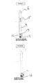
- FIG. 1 A bedside table or cabinet 1 , according to one illustrative embodiment of the invention, is shown in FIG. 1 . It is based alongside the head end of a hospital, nursing home or long-term care (LTC) bed 2 .
- LTC long-term care
- the cabinet rests on the floor adjacent the bed (it can also be fixed to the side of the bed or a wall behind the head end of the bed).
- the weight of the cabinet and/or any fixing to the bed or wall mean that its position is substantially fixed, or only moveable when subject to significant force (which are greater than those involved in a person lifting themselves out of the bed in the manner described below).
- a slideable drawer element 3 is supported on drawer rails 4 (see FIG. 5 ) and capable of movement out from under the upper or top surface 5 of the cabinet.
- the cabinet's slideable drawer element has an upwardly extending handle 6 at its front edge.
- the handle is coupled to the top of support pillars 7 whose bottom portions 8 rest on the floor.
- a front facing planar surface element 9 is supported between the two parallel support pillars 7 within channels 10 in the inner surface of each of the support pillars such that it can slide along the channels in the directions as shown in FIG. 8 .
- the bottom 11 of the front surface element 9 is fixed to the top of a U-shaped bracket 12 .
- the U-shaped bracket has a rubber pad 13 fixed or coupled to its upper surface by a spring 14 which biases the rubber gripping element 13 downwards.
- the brackets 12 and corresponding rubber pads 13 can move between an upper position (see FIG. 9a ) in which the pads 13 rest lightly on the floor and a lower position (see FIG. 9b ) in which the pads 13 are pressed down on the floor (see FIG. 9b ) with the springs 14 in a compressed state to increase the gripping action and thereby secure the slideable element 3 against movement relative to and along the floor.
- a cam actuator element or handle 15 is pivotally mounted above the front surface element 9 .
- a cam and cam follower arrangement (not shown) are provided such that when the cam actuator handle 15 is in the upright position (see FIG. 9b ), the front surface element 9 is pushed down to the lower position and, when it is in an angled position (see FIG. 9a ), the front surface element 9 moves to its upper position under the action of the springs 14. Movement of the handle 15 raises and/or lowers the bracket 12 and hence, respectively releases or secures the slideable drawer 3 against the floor.
- the slideable element or drawer 3 can be disposed in a retracted position with the handle 6 substantially flush against the front of the remainder of the bedside cabinet 1 , or in an extended position (as in FIGS. 2a and 2b ) with the front edge of the drawer 3 and handle 6 located thereon separated from the front edge of the remainder of the cabinet.
- a person wishing to lift himself or herself out of the bed can locate the slideable element 3 and its handle 6 at a position of his or her choosing alongside the bed 2 such that he or she can use it to lift themselves out of the bed. They can also access the drawer when the slideable 3 element is in its extended or open position.
- a person wishing to lift themselves out of bed moves the cam actuator element 15 to its unlocking or angled position (as shown in FIG. 9a ) to allow movement of the slideable element 3 relative to the remainder of the fixed cabinet and the floor on which the cabinet sits.
- the person then positions the slideable element 3 in the desired position before then allowing the cam actuator 15 to return to its upright position and thereby secure the slideable element 3 against further movement.
- the person can now use the handle 6 arranged alongside the bed to lift themselves out of bed into an upright position or, for example, into a wheelchair or other chair located next to the bed.
- the gripper pads 3 could be replaced by a roller or castor element which can be locked into place by movement of a pin into a ratchet or tooth arranged around the castor wheel.
- the pin or locking element could be controlled by a cam arrangement similar to that described above in connection with the embodiments of FIGS. 6-9 b.
Abstract
A table, cabinet or similar item of furniture particularly useful as a bedside cabinet next to a bed for a weak, elderly or infirm person. The cabinet (1) includes a slideable element (3). The slideable element (3) can be slided into an extended position such that an upwardly extending handle (6) on its front end can be used to help a person get in and out of the bed (2).
Description
- The present application is concerned with a table, cabinet or similar item of furniture suitable for use alongside a persons support apparatus, such as a bed for an elderly or infirm person.
- It can be difficult for an elderly, weak or unwell person to get out of a bed unaided. Beds designed for use by weak, elderly or unwell people (for example beds for use in nursing homes) sometimes have a handle arranged on the side of the bed to help with the initial lifting out from the bed. However, such a handle only helps with the initial lifting up as once the person has lifted themselves more than a small amount, the handle is behind them and therefore difficult to use for further lifting. This is particularly true for the elderly or infirm who typically have weakened muscles.
- A separate dedicated lifting apparatus such as crutches, walking sticks or walking frames can be used but these take up space next to a bed or in a room and are usually of an inappropriate height for optimal help to the person lifting himself or herself out of the bed.
- A need exists for apparatus to help a person lift themselves out from a bed but which yet does not take up considerable amounts of space when not in use.
- The present invention provides a table, cabinet or similar item of furniture, as defined in Claim 1 to which reference should now be made. The preferred features are defined in the dependent claims to which reference should also be made.
- The arrangement of Claim 1 allows provides an aesthetically pleasing and space-saving arrangement which helps someone get themselves more easily out of bed. An additional advantage of the invention is that it has less of a hospital-like appearance than the known arrangements. This has potentially important psychological and comfort impact on elderly patients in, for example, nursing homes where one is trying to create an atmosphere and feeling of being in one's home, rather than a hospital.
- Preferably, the said first side of the said upper surface is the front of the table, cabinet or similar item of furniture and said handle and said floor engaging element are disposed on the front edge of said slideable element.
- This arrangement makes for a simple and aesthetically pleasing item of furniture.
- Preferably, the table, cabinet or similar item of furniture includes two downwardly extending floor-engaging elements.
- The provision of two downwardly extending floor-engaging elements provides for increased stability when someone is lifting themselves out of bed using the handles.
- Preferably, the locking element is controlled by a cam arrangement on the upper proportion of the slideable element.
- The provision of a cam arrangement allows for simple and effective movement of the locking element. This is important where one is concerned with elderly and infirm operators.
- Preferably, the cam arrangement includes a handle coupled to a cam follower.
- This arrangement allows for easy operation by a person wishing to release and/or secure the slideable element.
- Preferably, movement of the handle and the cam element moves the locking element in a direction substantially perpendicular to the floor to thereby raise and lower the locking element to, respectively, release and secure the floor engaging element relative to the floor.
- This allows for easy and secure release and securing of the slideable element.
- Preferably, the table, cabinet or similar item of furniture is a bedside table or cabinet.
- Preferably, the table, cabinet or similar item of furniture is a drawer unit.
- The invention will now be described by way of nonlimiting example with reference to the accompanying drawings, in which:
-
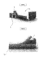
FIGS. 1a and 1b are, respectively, a perspective side view and a side view of a table, cabinet or similar item of furniture embodying the present invention alongside a patient's support apparatus, which is a bed; -
FIGS. 2a and 2b are, respectively, a side perspective view and a side view corresponding toFIGS. 1a and 1b but in which the slideable element is extended; -
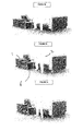
FIGS. 3a-3c illustrate how the extended slideable element can be used to facilitate a person lifting themselves out of a bed placed alongside the table, cabinet or similar item of furniture. -
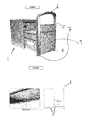
FIG. 4 is a side perspective view of the table, cabinet or similar item of furniture shown in FIGS ; -
FIG. 5 illustrates the sliding mechanism of the unit inFIG. 4 ; -
FIG. 6 illustrates the floor engaging and locking elements of the table, cabinet or similar item of furniture; -
FIG. 7 is a detailed view of the upper portion ofFIG. 6 ; -
FIG. 8 is a detailed view of the floor-engaging element ofFIG. 6 ; and -
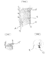
FIGS. 9a and 9b illustrate the operation of the locking mechanism for the floor-engaging elements. - A bedside table or cabinet 1, according to one illustrative embodiment of the invention, is shown in
FIG. 1 . It is based alongside the head end of a hospital, nursing home or long-term care (LTC)bed 2. - The cabinet rests on the floor adjacent the bed (it can also be fixed to the side of the bed or a wall behind the head end of the bed). The weight of the cabinet and/or any fixing to the bed or wall mean that its position is substantially fixed, or only moveable when subject to significant force (which are greater than those involved in a person lifting themselves out of the bed in the manner described below).
- A slideable drawer element 3 is supported on drawer rails 4 (see
FIG. 5 ) and capable of movement out from under the upper or top surface 5 of the cabinet. - The cabinet's slideable drawer element has an upwardly extending
handle 6 at its front edge. The handle is coupled to the top ofsupport pillars 7 whosebottom portions 8 rest on the floor. - A front facing
planar surface element 9 is supported between the twoparallel support pillars 7 within channels 10 in the inner surface of each of the support pillars such that it can slide along the channels in the directions as shown inFIG. 8 . Thebottom 11 of thefront surface element 9 is fixed to the top of aU-shaped bracket 12. The U-shaped bracket has arubber pad 13 fixed or coupled to its upper surface by aspring 14 which biases therubber gripping element 13 downwards. Thebrackets 12 andcorresponding rubber pads 13 can move between an upper position (seeFIG. 9a ) in which thepads 13 rest lightly on the floor and a lower position (seeFIG. 9b ) in which thepads 13 are pressed down on the floor (seeFIG. 9b ) with thesprings 14 in a compressed state to increase the gripping action and thereby secure the slideable element 3 against movement relative to and along the floor. - A cam actuator element or
handle 15 is pivotally mounted above thefront surface element 9. A cam and cam follower arrangement (not shown) are provided such that when thecam actuator handle 15 is in the upright position (seeFIG. 9b ), thefront surface element 9 is pushed down to the lower position and, when it is in an angled position (seeFIG. 9a ), thefront surface element 9 moves to its upper position under the action of thesprings 14. Movement of thehandle 15 raises and/or lowers thebracket 12 and hence, respectively releases or secures the slideable drawer 3 against the floor. - As shown in
FIG. 1 , the slideable element or drawer 3 can be disposed in a retracted position with thehandle 6 substantially flush against the front of the remainder of the bedside cabinet 1, or in an extended position (as inFIGS. 2a and 2b ) with the front edge of the drawer 3 andhandle 6 located thereon separated from the front edge of the remainder of the cabinet. - As shown in
FIGS. 3a-3c , a person wishing to lift himself or herself out of the bed can locate the slideable element 3 and itshandle 6 at a position of his or her choosing alongside thebed 2 such that he or she can use it to lift themselves out of the bed. They can also access the drawer when the slideable 3 element is in its extended or open position. - A person wishing to lift themselves out of bed moves the
cam actuator element 15 to its unlocking or angled position (as shown inFIG. 9a ) to allow movement of the slideable element 3 relative to the remainder of the fixed cabinet and the floor on which the cabinet sits. The person then positions the slideable element 3 in the desired position before then allowing thecam actuator 15 to return to its upright position and thereby secure the slideable element 3 against further movement. The person can now use thehandle 6 arranged alongside the bed to lift themselves out of bed into an upright position or, for example, into a wheelchair or other chair located next to the bed. - In an alternative embodiment (not shown), the gripper pads 3 could be replaced by a roller or castor element which can be locked into place by movement of a pin into a ratchet or tooth arranged around the castor wheel. The pin or locking element could be controlled by a cam arrangement similar to that described above in connection with the embodiments of
FIGS. 6-9 b.
Claims (9)
- A table, cabinet or similar item of furniture (1) comprising a top surface (5), a slideable element (3) slideable between a first retracted position in which it is substantially underneath said top surface and at least one further extended position in which it projects out from underneath a first side of said upper surface, and wherein the slideable element includes an upwardly facing handle (6), at least one downwardly extending floor engaging element (13) and a locking element (12, 14) to secure the at least one floor engaging element relative to the floor or surface on which the table, cabinet or similar item of furniture sits.
- A table, cabinet or similar item of furniture according to claim 1 wherein the said first side of the said upper surface is the front of the table, cabinet or similar item of furniture and said handle (6) and said floor engaging element are disposed on the front edge of said slideable element.
- A table, cabinet or similar item of furniture according to any preceding claim comprising at least two downwardly extending floor-engaging elements (13).
- A table, cabinet or similar item of furniture according to any preceding claim wherein the locking element (12, 14) is controlled by a cam arrangement on the upper portion of the slideable element.
- A table, cabinet or similar item of furniture according to claim 4 wherein the cam arrangement includes a handle (15) coupled to a cam element.
- A table, cabinet or similar item of furniture according to claim 5 wherein movement of the handle (15) and the cam element moves the locking element (12, 14) in a direction substantially perpendicular to the floor to thereby raise and lower the locking element to, respectively, release and secure the floor engaging element (13) relative to the floor.
- A bedside table or cabinet according to any preceding claim.
- A drawer unit according to any preceding claim.
- A table, cabinet or similar item of furniture according to any preceding claim wherein the slideable element is a drawer running on drawer rails.
Priority Applications (1)
| Application Number | Priority Date | Filing Date | Title |
|---|---|---|---|
| EP12168519.2A EP2664253A1 (en) | 2012-05-18 | 2012-05-18 | A table, cabinet or similar item of furniture |
Applications Claiming Priority (1)
| Application Number | Priority Date | Filing Date | Title |
|---|---|---|---|
| EP12168519.2A EP2664253A1 (en) | 2012-05-18 | 2012-05-18 | A table, cabinet or similar item of furniture |
Publications (1)
| Publication Number | Publication Date |
|---|---|
| EP2664253A1 true EP2664253A1 (en) | 2013-11-20 |
Family
ID=46125258
Family Applications (1)
| Application Number | Title | Priority Date | Filing Date |
|---|---|---|---|
| EP12168519.2A Withdrawn EP2664253A1 (en) | 2012-05-18 | 2012-05-18 | A table, cabinet or similar item of furniture |
Country Status (1)
| Country | Link |
|---|---|
| EP (1) | EP2664253A1 (en) |
Cited By (2)
| Publication number | Priority date | Publication date | Assignee | Title |
|---|---|---|---|---|
| CN110314053A (en) * | 2018-03-30 | 2019-10-11 | 八乐梦医用床有限公司 | Body support |
| CN112535587A (en) * | 2020-12-09 | 2021-03-23 | 中日友好医院(中日友好临床医学研究所) | Special portable disinfection bedside cupboard of critical patient |
Citations (2)
| Publication number | Priority date | Publication date | Assignee | Title |
|---|---|---|---|---|
| GB1232649A (en) * | 1968-02-29 | 1971-05-19 | ||
| US20060016014A1 (en) * | 2003-07-31 | 2006-01-26 | Thaxton Bart J | Apparatus and system for supporting an individual during repositioning |
-
2012
- 2012-05-18 EP EP12168519.2A patent/EP2664253A1/en not_active Withdrawn
Patent Citations (2)
| Publication number | Priority date | Publication date | Assignee | Title |
|---|---|---|---|---|
| GB1232649A (en) * | 1968-02-29 | 1971-05-19 | ||
| US20060016014A1 (en) * | 2003-07-31 | 2006-01-26 | Thaxton Bart J | Apparatus and system for supporting an individual during repositioning |
Cited By (3)
| Publication number | Priority date | Publication date | Assignee | Title |
|---|---|---|---|---|
| CN110314053A (en) * | 2018-03-30 | 2019-10-11 | 八乐梦医用床有限公司 | Body support |
| CN110314053B (en) * | 2018-03-30 | 2022-03-22 | 八乐梦医用床有限公司 | Body support device |
| CN112535587A (en) * | 2020-12-09 | 2021-03-23 | 中日友好医院(中日友好临床医学研究所) | Special portable disinfection bedside cupboard of critical patient |
Similar Documents
| Publication | Publication Date | Title |
|---|---|---|
| US8899682B2 (en) | Item of furniture | |
| JP5329275B2 (en) | Chair | |
| KR20200138824A (en) | Multifunctional wheelchair | |
| US6907625B2 (en) | Sliding bed | |
| CN201987776U (en) | Detachable nursing bed chair | |
| CN107049638B (en) | It is a kind of to help the collapsible wheelchair easy to transfer and first aid certainly with old man | |
| US10980338B1 (en) | Table with multiple horizontally and vertically adjustable table top sections | |
| KR20170101333A (en) | electric wheelchair for bad-movement | |
| EP2664253A1 (en) | A table, cabinet or similar item of furniture | |
| KR101295627B1 (en) | A health pillow of an ascent and descent type | |
| KR20180104432A (en) | Wheelchair accessible to the patient on the bed | |
| TWI693932B (en) | Care robot | |
| KR20130098508A (en) | A moving method for a patient paralyzed from the waist down | |
| JP3988032B2 (en) | Sliding bed | |
| GB2399282A (en) | Sliding and tilting chair for transferring person to bed | |
| CN208355015U (en) | A kind of seat | |
| JP6317625B2 (en) | Mobility aid | |
| TWM582384U (en) | Nursing robot | |
| KR20200002852U (en) | A wheelchair that caregiver to easily care for patient | |
| JP3202436U (en) | Transfer device | |
| WO2020184250A1 (en) | Care bed | |
| CN215914391U (en) | Toilet seat auxiliary device for old people nursing | |
| CN215532980U (en) | Folding chair for pedicure | |
| KR101853911B1 (en) | Joint chair protection | |
| WO2015186093A1 (en) | Seating element |
Legal Events
| Date | Code | Title | Description |
|---|---|---|---|
| PUAI | Public reference made under article 153(3) epc to a published international application that has entered the european phase |
Free format text: ORIGINAL CODE: 0009012 |
|
| AK | Designated contracting states |
Kind code of ref document: A1 Designated state(s): AL AT BE BG CH CY CZ DE DK EE ES FI FR GB GR HR HU IE IS IT LI LT LU LV MC MK MT NL NO PL PT RO RS SE SI SK SM TR |
|
| AX | Request for extension of the european patent |
Extension state: BA ME |
|
| STAA | Information on the status of an ep patent application or granted ep patent |
Free format text: STATUS: THE APPLICATION IS DEEMED TO BE WITHDRAWN |
|
| 18D | Application deemed to be withdrawn |
Effective date: 20140521 |