EP2664077B1 - Method and system for communcating data over the power line - Google Patents
Method and system for communcating data over the power line Download PDFInfo
- Publication number
- EP2664077B1 EP2664077B1 EP11779590.6A EP11779590A EP2664077B1 EP 2664077 B1 EP2664077 B1 EP 2664077B1 EP 11779590 A EP11779590 A EP 11779590A EP 2664077 B1 EP2664077 B1 EP 2664077B1
- Authority
- EP
- European Patent Office
- Prior art keywords
- transmit
- communications device
- carriers
- roll
- ofdm symbols
- Prior art date
- Legal status (The legal status is an assumption and is not a legal conclusion. Google has not performed a legal analysis and makes no representation as to the accuracy of the status listed.)
- Active
Links
- 238000000034 method Methods 0.000 title claims description 16
- 239000000969 carrier Substances 0.000 claims description 106
- 238000004891 communication Methods 0.000 claims description 82
- 230000005540 biological transmission Effects 0.000 description 8
- 238000010586 diagram Methods 0.000 description 8
- 238000007493 shaping process Methods 0.000 description 5
- 238000001228 spectrum Methods 0.000 description 4
- 230000002457 bidirectional effect Effects 0.000 description 3
- 238000001914 filtration Methods 0.000 description 3
- 230000003595 spectral effect Effects 0.000 description 2
- 230000001419 dependent effect Effects 0.000 description 1
- 230000006855 networking Effects 0.000 description 1
- 230000011664 signaling Effects 0.000 description 1
- 230000009466 transformation Effects 0.000 description 1
- 230000001131 transforming effect Effects 0.000 description 1
Images


Classifications
-
- H—ELECTRICITY
- H04—ELECTRIC COMMUNICATION TECHNIQUE
- H04B—TRANSMISSION
- H04B3/00—Line transmission systems
- H04B3/54—Systems for transmission via power distribution lines
- H04B3/542—Systems for transmission via power distribution lines the information being in digital form
-
- H—ELECTRICITY
- H04—ELECTRIC COMMUNICATION TECHNIQUE
- H04L—TRANSMISSION OF DIGITAL INFORMATION, e.g. TELEGRAPHIC COMMUNICATION
- H04L27/00—Modulated-carrier systems
- H04L27/26—Systems using multi-frequency codes
- H04L27/2601—Multicarrier modulation systems
- H04L27/2602—Signal structure
- H04L27/2605—Symbol extensions, e.g. Zero Tail, Unique Word [UW]
- H04L27/2607—Cyclic extensions
-
- H—ELECTRICITY
- H04—ELECTRIC COMMUNICATION TECHNIQUE
- H04B—TRANSMISSION
- H04B2203/00—Indexing scheme relating to line transmission systems
- H04B2203/54—Aspects of powerline communications not already covered by H04B3/54 and its subgroups
- H04B2203/5404—Methods of transmitting or receiving signals via power distribution lines
- H04B2203/5408—Methods of transmitting or receiving signals via power distribution lines using protocols
-
- H—ELECTRICITY
- H04—ELECTRIC COMMUNICATION TECHNIQUE
- H04B—TRANSMISSION
- H04B2203/00—Indexing scheme relating to line transmission systems
- H04B2203/54—Aspects of powerline communications not already covered by H04B3/54 and its subgroups
- H04B2203/5404—Methods of transmitting or receiving signals via power distribution lines
- H04B2203/5416—Methods of transmitting or receiving signals via power distribution lines by adding signals to the wave form of the power source
-
- H—ELECTRICITY
- H04—ELECTRIC COMMUNICATION TECHNIQUE
- H04B—TRANSMISSION
- H04B2203/00—Indexing scheme relating to line transmission systems
- H04B2203/54—Aspects of powerline communications not already covered by H04B3/54 and its subgroups
- H04B2203/5429—Applications for powerline communications
- H04B2203/5445—Local network
-
- H—ELECTRICITY
- H04—ELECTRIC COMMUNICATION TECHNIQUE
- H04B—TRANSMISSION
- H04B2203/00—Indexing scheme relating to line transmission systems
- H04B2203/54—Aspects of powerline communications not already covered by H04B3/54 and its subgroups
- H04B2203/5429—Applications for powerline communications
- H04B2203/5454—Adapter and plugs
-
- H—ELECTRICITY
- H04—ELECTRIC COMMUNICATION TECHNIQUE
- H04L—TRANSMISSION OF DIGITAL INFORMATION, e.g. TELEGRAPHIC COMMUNICATION
- H04L5/00—Arrangements affording multiple use of the transmission path
- H04L5/0091—Signaling for the administration of the divided path
Definitions
- the invention relates to a system and a communications device for transmitting data via a powerline and a corresponding method.
- orthogonal frequency division multiplexing is used for transmitting data from a first communications device, e.g. a transmitter to a second communications device, e.g. a receiver.
- OFDM orthogonal frequency division multiplexing
- the orthogonality of the sub-carriers allows a per-carrier demodulation at the receiver side, since at the receiver side the demodulators are prevented from considering other sub-carriers than that one there are dedicated to.
- OFDM provides high spectral efficiency and allows subcarrier selection and modulation to be adapted to the transmission channel characteristics.
- An example of prior art can be found in US6115354 . It is an object of the invention to provide a system, a communications device with enhanced transmission performance and a method for transmitting data via a powerline, which provides enhanced transmission performance in a communication system.
- FIG. 1 a schematic block diagram of a system 100 for transmitting data via a powerline is depicted.
- the system 100 is based on an OFDM modulation scheme.
- the system 100 is a power line communications (PLC), mains communications, power line telecommunications (PLT), broadband power line (BPL) or power band or power line networking (PLN) system using modulated carriers superimposed to the power line alternating current, which may have a frequency of 50 or 60 Hz, by way of example.
- PLC power line communications
- mains communications mains communications
- PLT power line telecommunications
- BPL broadband power line
- PPN power band or power line networking
- the system 100 comprises a first communications device 102 including a transmit unit 110 and a second communications device 104 including a receive unit 120.
- the first communications device 102 and the second communications device 104 might also be referred to as “modems”, “PLC modems (powerline communications modems", “nodes” or “PLC nodes (powerline communications nodes)”.
- modems modems
- PLC modems powerline communications modems
- nodes nodes
- PLC nodes powerline communications nodes
- the system 100 may be a SISO (single-input-single-output) or a MIMO (multiple-input-multiple-output) system.
- a transmission channel 101 connects the transmit unit 110 and the receive unit 120.
- the first communications device 102 may be an exclusively transmitting device with one or a plurality of transmit ports only. According to other embodiments, the first communication device 102 is a bidirectional device including, in addition to the transmit unit 110, a receive unit 150 which may be of the type of a receive unit 120 in the second communications device 104.
- the second communications device 104 may be an exclusively receiving device. According to other embodiments, the second communications device 104 is a bidirectional device including, in addition to the receive unit 120, a transmit unit 160 which may be of the type of the transmit unit 110 in the first communications device 102.
- the communications devices 102, 104 may be stand-alone devices or may be integrated in an electronic device for consumer applications, for example a storage unit, a television set, an audio receiver, or a video recorder.
- the transmit unit 110 is adapted to generate OFDM symbols to be transmitted using sub-carriers by transforming incoming data 170.
- the first communications device 102 further includes a roll-off interval indication unit 112 adapted to generate a transmit message indicating that no roll-off interval before and/or after the OFDM symbols is used when transmitting the data.
- the transmit unit 110 is further adapted to transmit the transmit message to the receive unit 120 of the second communications device 104.
- the receive unit 120 is adapted to generate outgoing data 190, which is intended to correspond to the incoming data 170, from the transmitted OFDM symbols by taking into account the received transmit message.
- the second communications device 104 might further include a roll-off interval handling unit 122 adapted to generate a receive message indicating that the receive unit 120 is able to handle OFDM symbols without roll-off interval before and/or after the OFDM symbols.
- the further transmit unit 160 is adapted to transmit the receive message to the receive unit 150 of the first communications device 102.
- the transmit message might also be referred to as transmit information, transmit flag or transmit bit(s). Since the message conveys the information whether a roll-off interval is used or not, a single bit for the transmit message can be used, using only a limited amount of further communications resources.
- Fig. 2 method steps of a corresponding method are depicted.
- a step S200 OFDM symbols are generated.
- a transmit message indicating that no roll-off interval is used is generated in S202.
- the transmit message is transmitted to the receive unit 120 in step S204.
- a roll-off interval T roll-off is frequently used as a method to shape OFDM spectra.
- a roll-off interval is added to the symbol time even if this causes a loss of communication resources in time domain.
- a frequency range of conventional powerline transmission (PLT) modems (2 MHz to 30 MHz) overlaps with frequency ranges of HF (high frequency) radio services.
- Powerline wires in private homes are not shielded and due to branches, distribution boxes etc. the powerline network is structured with a certain amount of asymmetry.
- the asymmetries of the powerline network convert the differentially set signals into common mode signals, which tend to interfere with radio devices. If e.g.
- SW short wave
- AM amplitude modulation
- DRM digital radio management
- guard carriers on the left and right side of the notch must be omitted.
- Future norms e.g. CENELEC TC210
- CENELEC TC210 will request more notches. Some of the new notches are quite small. Additional loss of resources will be caused due to the guard carriers adjacent to the multiple notches.
- a Homeplug powerline communication modem removes usually four guard carriers on the left and right side of the notch.
- the Homeplug AV 1.1 specification which was introduced in August 2005, provides sufficient bandwidth for applications such as HDTV and VoIP. It is also possible to only remove three carriers.
- eight notches are listed.
- a European EMI norm from CENELEC TC210 requests eighteen permanent notches plus any number of dynamic notches to protect HF radio broadcast. In average ten dynamic notches might be expected.
- guard carriers are needed.
- the process of shaping the slopes at the beginning and the end of a symbol is also known under the term "windowing".
- the two descending slopes in the time domain could overlap in order to save communication resources at consecutive OFDM symbols.
- the guard interval T GI and the descending slopes T roll-off are added before the fast Fourier transformation (FFT) section T FFT .
- the overhead caused by the additional window is called T prefix , when the guard interval GI is included and either T postfix or T roll-off when the guard interval GI is excluded.
- the new symbol time T s is measured between the middles of the roll-off intervals before and after the symbol.
- the missing roll-off interval is signaled with the transmit message from the first communications device 102 to the second communications device 104.
- Such a signaling may be realized by transmitting the transmit message in a field in the sound MPDU (Medium Access Control Physical Data Unit) variant field, e.g. by a single bit, which is used in a channel estimation process between two communication devices.
- the Medium Access Control Physical Data Unit (MPDU) is a unit of data exchange between two peers MAC entities using the services of a physical layer.
- Table 1 Bit allocation for Sound MPDU Variant Field Field Octet Number Bit Number Field Size (Bits) Definition DT_AV 0 0 - 2 3 0b 100 (Delimiter Type) ACCESS 3 1 Access Field SNID 4 - 7 4 Short Network Identifier STEI 1 0 - 7 8 Source Terminal Equipment Identifier DTEI 2 0 - 7 8 Destination Terminal Equipment Identifier LID 3 0 - 7 8 Link Identifier CFS 4 0 1 Contention-Free Session PBSz 1 1 PHY Block Size BDF 2 1 Beacon Detect Flag SAF 3 1 Sound ACK Flag SCF 4 1 Sound Complete Flag REQ_TM 5 - 7 3 Max Tone Maps Requested FL_AV 5 0 - 7 12 HomePlug Av Frame Length 6 0 - 3 MPDUCnt 4 - 5 2 MPDU Count NO ROI 6 1 No Rolloff Interval RSVD 7 1 Reserved PPB 7 0 - 7 8 Pending PHY Blocks SRC 8 0 -
- NO_ROI no roll-off interval
- the message or flag "no roll-off interval” indicates that there will be no pulse shaping in the time domain in-between the dataflow.
- the first communications device 102 indicates that it guarantees notch characteristics (depth and slopes) even without pulse shaping in time domain.
- the second communications device 104 has to confirm its abilities to receive the dataflow without roll-off interval in its corresponding response by setting the NO_ROI interval also to "1".
- first communications device 102 or the second communications device 104 does not support communication without roll-off interval (e.g. if backward compatibility to earlier home plug nodes or powerline communication modems shall be guaranteed) this bit shall be set to "zero" ("0") and the roll-off interval will be inserted.
- Fig. 4 schematic block diagram of a corresponding method is depicted.
- S200 OFDM symbols are generated and in S202 the transmit message indicating that no roll-off interval is used is generated. Afterwards the transmit message is transmitted to the receive unit 120 in a sound MPDU variant field in S404. After receiving the transmit message in S406 a receive message is generated indicating that the receive unit 120 is able to handle OFDM symbols without roll-off interval. In S410 the receive message is transmitted in a sound MPDU variant field from the second communications device 104 to the first communications device 102.
- the communication in a robust mode (“ROBO mode") or initialization mode keeps the roll-off interval. If the roll-off interval is removed 4.96 microseconds of communication resources in time domain are saved between all OFDM symbols in the dataflow.
- a corresponding European carrier mask might be established like as depicted in table 3.
- a schematic block diagram of a first communications device 402, including a transmit unit 410 is depicted.
- the transmit unit 410 is adapted to generate OFDM symbols to be transmitted using sub-carriers.
- the first communications device 402 further includes a roll-off interval indication unit 412 adapted to generate a transmit message indicating that no roll-off interval before and/or after the OFDM symbols is used when transmitting the data.
- the transmit unit 410 is further adapted to transmit the transmit message.
- the first communications device 402 may be an exclusively transmitting device with one or a plurality of transmit ports only. According to other embodiments, the first communication device 402 is a bidirectional device including, in addition to the transmit unit 410, a receive unit 450 adapted to receive data from a further communications device.
- a second communications device 504 is depicted as a schematic block diagram.
- the second communications device 504 includes a receive unit 520 adapted to generate the data from the transmitted OFDM symbols by taking into account a received transmit message.
- the second communications device 504 further includes a roll-off interval handling unit 522 adapted to generate a receive message indicating that the receive unit 120 is able to handle OFDM symbols without roll-off interval before and/or after the OFDM symbols.
- a further transmit unit 524 is included which is adapted to transmit the receive message to a further communications device.
Landscapes
- Engineering & Computer Science (AREA)
- Computer Networks & Wireless Communication (AREA)
- Signal Processing (AREA)
- Power Engineering (AREA)
- Cable Transmission Systems, Equalization Of Radio And Reduction Of Echo (AREA)
Description
- The invention relates to a system and a communications device for transmitting data via a powerline and a corresponding method.
- In powerline communication orthogonal frequency division multiplexing (OFDM) is used for transmitting data from a first communications device, e.g. a transmitter to a second communications device, e.g. a receiver. OFDM distributes data over a large number of orthogonal sub-carriers. The orthogonality of the sub-carriers allows a per-carrier demodulation at the receiver side, since at the receiver side the demodulators are prevented from considering other sub-carriers than that one there are dedicated to. OFDM provides high spectral efficiency and allows subcarrier selection and modulation to be adapted to the transmission channel characteristics. An example of prior art can be found in
US6115354 . It is an object of the invention to provide a system, a communications device with enhanced transmission performance and a method for transmitting data via a powerline, which provides enhanced transmission performance in a communication system. - The object is achieved by the subject-matters of the independent claims. Further embodiments are specified in the dependent claims, respectively. Details of the invention will become more apparent from the following description of embodiments in connection with the accompanying drawings, wherein features of the various embodiments may be combined unless they exclude each other.
-
- Fig. 1
- shows a schematic block diagram of a system according to an embodiment of the invention,
- Fig. 2
- shows schematically steps of a method according to an embodiment of the invention,
- Fig .3
- shows a schematic time diagram of consecutive OFDM symbols, guard intervals and roll-off intervals,
- Fig. 4
- shows schematically steps of a method according to an embodiment of the invention,
- Fig. 5
- shows a schematic block diagram of a first communications device including a transmit unit according to an embodiment of the invention, and
- Fig. 6
- shows a schematic block diagram of a second communications device including a receive unit according to a further embodiment of the invention.
- In
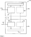
Fig. 1 a schematic block diagram of asystem 100 for transmitting data via a powerline is depicted. - The
system 100 is based on an OFDM modulation scheme. For example, thesystem 100 is a power line communications (PLC), mains communications, power line telecommunications (PLT), broadband power line (BPL) or power band or power line networking (PLN) system using modulated carriers superimposed to the power line alternating current, which may have a frequency of 50 or 60 Hz, by way of example. - The
system 100 comprises a first communications device 102 including atransmit unit 110 and a second communications device 104 including areceive unit 120. - The first communications device 102 and the second communications device 104 might also be referred to as "modems", "PLC modems (powerline communications modems", "nodes" or "PLC nodes (powerline communications nodes)".
- The
system 100 may be a SISO (single-input-single-output) or a MIMO (multiple-input-multiple-output) system. A transmission channel 101 connects thetransmit unit 110 and the receiveunit 120. - The first communications device 102 may be an exclusively transmitting device with one or a plurality of transmit ports only. According to other embodiments, the first communication device 102 is a bidirectional device including, in addition to the
transmit unit 110, a receive unit 150 which may be of the type of areceive unit 120 in the second communications device 104. The second communications device 104 may be an exclusively receiving device. According to other embodiments, the second communications device 104 is a bidirectional device including, in addition to the receiveunit 120, atransmit unit 160 which may be of the type of thetransmit unit 110 in the first communications device 102. The communications devices 102, 104 may be stand-alone devices or may be integrated in an electronic device for consumer applications, for example a storage unit, a television set, an audio receiver, or a video recorder. - The
transmit unit 110 is adapted to generate OFDM symbols to be transmitted using sub-carriers by transformingincoming data 170. - The first communications device 102 further includes a roll-off interval indication unit 112 adapted to generate a transmit message indicating that no roll-off interval before and/or after the OFDM symbols is used when transmitting the data.
- The
transmit unit 110 is further adapted to transmit the transmit message to the receiveunit 120 of the second communications device 104. - The receive
unit 120 is adapted to generateoutgoing data 190, which is intended to correspond to theincoming data 170, from the transmitted OFDM symbols by taking into account the received transmit message. - The second communications device 104 might further include a roll-off interval handling unit 122 adapted to generate a receive message indicating that the receive
unit 120 is able to handle OFDM symbols without roll-off interval before and/or after the OFDM symbols. In this embodiment thefurther transmit unit 160 is adapted to transmit the receive message to the receive unit 150 of the first communications device 102. - The transmit message might also be referred to as transmit information, transmit flag or transmit bit(s). Since the message conveys the information whether a roll-off interval is used or not, a single bit for the transmit message can be used, using only a limited amount of further communications resources.
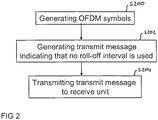
- In
Fig. 2 method steps of a corresponding method are depicted. In a step S200 OFDM symbols are generated. A transmit message indicating that no roll-off interval is used is generated in S202. The transmit message is transmitted to the receiveunit 120 in step S204. - As depicted in
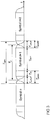
Fig. 3 in today's powerline modems a roll-off interval Troll-off is frequently used as a method to shape OFDM spectra. A roll-off interval is added to the symbol time even if this causes a loss of communication resources in time domain. A frequency range of conventional powerline transmission (PLT) modems (2 MHz to 30 MHz) overlaps with frequency ranges of HF (high frequency) radio services. Powerline wires in private homes are not shielded and due to branches, distribution boxes etc. the powerline network is structured with a certain amount of asymmetry. The asymmetries of the powerline network convert the differentially set signals into common mode signals, which tend to interfere with radio devices. If e.g. a short wave (SW) radio receiver (AM (amplitude modulation) or DRM (digital radio mondiale)) is operated indoors where a powerline communication is active, the radio reception quality might suffer. When the radio device is connected to the mains power supply and the radio has an insufficient decoupling at its mains port, the conducted path is especially dominant in terms of interference. Therefore, the coexistence between powerline transmission and HF radio reception is very important. In order to ensure coexistence of powerline transmission and HF radio services it is envisaged to notch the HF radio bands either statically or dynamically from the spectrum that is used by powerline transmission. Today's powerline communication modems have weak notching capabilities. Notches are implemented by just omitting sub-carriers of the OFDM spectrum without any additional filters. To guarantee notches of a depth of 30 dB in the desired frequency band additional guard carriers on the left and right side of the notch must be omitted. Future norms (e.g. CENELEC TC210) will request more notches. Some of the new notches are quite small. Additional loss of resources will be caused due to the guard carriers adjacent to the multiple notches. - Today e.g. a Homeplug powerline communication modem removes usually four guard carriers on the left and right side of the notch. The Homeplug AV 1.1 specification, which was introduced in August 2005, provides sufficient bandwidth for applications such as HDTV and VoIP. It is also possible to only remove three carriers. In today's Homeplug specification eight notches are listed. Probably the next version of a European EMI norm from CENELEC TC210 requests eighteen permanent notches plus any number of dynamic notches to protect HF radio broadcast. In average ten dynamic notches might be expected. Using today's implementation of notches up to 4 x 2 (18 + 10) = 224 guard carriers are needed. The current standard "Homeplug" uses a carrier spacing of 1/Tsymbol = 1/40.96 µs = 24.414 kHz. If up to 224 guard carriers are used 224 x 24,414 kHz = 5.469 MHz are wasted due to the notching practice.
- The process of shaping the slopes at the beginning and the end of a symbol is also known under the term "windowing". The more smoothly signals approach zero in the time domain, the deeper the notches are in the frequency domain. As shown in
Fig. 3 the two descending slopes in the time domain could overlap in order to save communication resources at consecutive OFDM symbols. The guard interval TGI and the descending slopes Troll-off are added before the fast Fourier transformation (FFT) section TFFT. The overhead caused by the additional window is called Tprefix, when the guard interval GI is included and either Tpostfix or Troll-off when the guard interval GI is excluded. The new symbol time Ts is measured between the middles of the roll-off intervals before and after the symbol. - However, when notches are implemented using digital filtering deep slopes of the notches and deep notches can be realized. Then, the pulse shaping in time domain can be avoided.
- In order to improve the interoperability between the first communications device 102 and the second communications device 104 the missing roll-off interval is signaled with the transmit message from the first communications device 102 to the second communications device 104.
- Such a signaling may be realized by transmitting the transmit message in a field in the sound MPDU (Medium Access Control Physical Data Unit) variant field, e.g. by a single bit, which is used in a channel estimation process between two communication devices. The Medium Access Control Physical Data Unit (MPDU) is a unit of data exchange between two peers MAC entities using the services of a physical layer.
-
Table 1: Bit allocation for Sound MPDU Variant Field Field Octet Number Bit Number Field Size (Bits) Definition DT_AV 0 0 - 2 3 0b 100 (Delimiter Type) ACCESS 3 1 Access Field SNID 4 - 7 4 Short Network Identifier STEI 1 0 - 7 8 Source Terminal Equipment Identifier DTEI 2 0 - 7 8 Destination Terminal Equipment Identifier LID 3 0 - 7 8 Link Identifier CFS 4 0 1 Contention- Free Session PBSz 1 1 PHY Block Size BDF 2 1 Beacon Detect Flag SAF 3 1 Sound ACK Flag SCF 4 1 Sound Complete Flag REQ_TM 5 - 7 3 Max Tone Maps Requested FL_AV 5 0 - 7 12 HomePlug Av Frame Length 6 0 - 3 MPDUCnt 4 - 5 2 MPDU Count NO ROI 6 1 No Rolloff Interval RSVD 7 1 Reserved PPB 7 0 - 7 8 Pending PHY Blocks SRC 8 0 - 7 8 Sound Reason Code RSVD 9 0 - 7 Reserved 10 0 - 7 11 0 - 7 12 0 - 7 FCCS_AV 13 0 - 7 24 Frame Control Check Sequence 14 0 - 7 15 0 - 7 - If the bit "no roll-off interval" ("NO_ROI") is set, the data communication between the two communication devices or nodes will not include time domain pulse shaping. The message or flag "no roll-off interval" indicates that there will be no pulse shaping in the time domain in-between the dataflow. By setting this bit to "1" the first communications device 102 indicates that it guarantees notch characteristics (depth and slopes) even without pulse shaping in time domain. The second communications device 104 has to confirm its abilities to receive the dataflow without roll-off interval in its corresponding response by setting the NO_ROI interval also to "1".
- If the first communications device 102 or the second communications device 104 does not support communication without roll-off interval (e.g. if backward compatibility to earlier home plug nodes or powerline communication modems shall be guaranteed) this bit shall be set to "zero" ("0") and the roll-off interval will be inserted.
- In
Fig. 4 schematic block diagram of a corresponding method is depicted. In S200 OFDM symbols are generated and in S202 the transmit message indicating that no roll-off interval is used is generated. Afterwards the transmit message is transmitted to the receiveunit 120 in a sound MPDU variant field in S404. After receiving the transmit message in S406 a receive message is generated indicating that the receiveunit 120 is able to handle OFDM symbols without roll-off interval. In S410 the receive message is transmitted in a sound MPDU variant field from the second communications device 104 to the first communications device 102. - To ensure backward compatibility to earlier home plug modems the communication in a robust mode ("ROBO mode") or initialization mode keeps the roll-off interval. If the roll-off interval is removed 4.96 microseconds of communication resources in time domain are saved between all OFDM symbols in the dataflow.
- A new North American spectrum mask if notches are implemented using digital filters is depicted in table 2 (PSD Limit: Power Spectral Density Limit).
Table 2: North American Carrier mask for HomePlug including notches by digital filtering Frequency F (MHz) PSD Limit (dBm/Hz) Carrier On/Off Notes F <= 1.71 -87 Carriers 0-70 are OFF AM broadcast band and lower 1.71<F<1.8 -80 Carriers 71-73 are OFF Between AM and 160-meter band 1.8 <= F <= 2.00 -80 Carriers 74-85 are OFF 160 meter amateur band 2.00 < F <3.5 -50 Carriers 86-143 are ON HomePlug carriers 3.5 <= F <= 4.00 -80 Carriers 144-163 are OFF 80 meter amateur band 4.000 < F < 5.33 -50 Carriers 164-218 are ON HomePlug carriers 5.33 <= F <= 5.407 -80 Carriers 219-221 are OFF 5 MHz amateur band 5.407 < F < 7.0 -50 Carriers 222-286 are ON HomePlug Carriers 7.0 <= F <= 7.3 -80 Carriers 287-299 are OFF 40 meter amateur band 7.3 < F < 10.10 -50 Carriers 300-413 are ON HomePlug carriers 10.10 <= F <= 10.15 -80 Carriers 414-415 are OFF 30 meter amateur band 10.15 < F < 14.00 -50 Carriers 416-573 are ON HomePlug carriers 14.00 <= F <= 14.35 -80 Carriers 574-587 are OFF 20 meter amateur band 14.35 < F < 18.068 -50 Carriers 588-740 are ON HomePlug carriers 18.068 <= F <= 18.168 -80 Carriers 741-744 are OFF 17 meter amateur band 18.168 < F < 21.00 -50 Carriers 745-860 are ON HomePlug carriers 21.000 <= F <= 21.45 -80 Carriers 861-878 are OFF 15 meter amateur band 21.45 < F < 24.89 -50 Carriers 879-1019 are ON HomePlug Carriers 24.89 <= F <= 24.99 -80 Carriers 1020-1023 are OFF 12 meter amateur band 24.99 < F < 28.0 -50 Carriers 1024-1146 are ON HomePlug Carriers F >= 28.0 -80 Carriers 1147-1535 are OFF 10 meter amateur band - A corresponding European carrier mask might be established like as depicted in table 3.
Table 3: European Carrier mask for HomePlug including notches by digital filtering Frequency F (MHz) PSD Limit (dBm/Hz) Carrier On/Off Notes F <= 1.71 -87 Carriers 0-70 are OFF AM broadcast band and lower 1.71<F<1.8 -80 Carriers 71-73 are OFF Between AM and 160-meter band 1.8 <= F <= 2.00 -80 Carriers 74-85 are OFF 160 meter amateur band 2.00 < F < 2.85 -50 Carriers 86-116 are ON HomePlug carriers 2.85 <= F <= 3.025 -80 Carriers 117-123 are OFF Aeronautical Mobile 3.025 < F < 3.4 -50 Carriers 124-139 are ON HomePlug carriers 3.4 <= F <= 4.00 -80 Carriers 144-163 are OFF Aeronautical Mobile + 80 meter amateur band 4.000 < F < 4.65 -50 Carriers 164-190 are ON HomePlug carriers 4.65 <= F <= 4.7 -80 Carriers 191-192 are OFF Aeronautical Mobile 4.7 < F < 5.25 -50 Carriers 193-215 are ON HomePlug carriers 5.25 <= F <= 5.41 -80 Carriers 216-221 are OFF 5 MHz amateur band 5.41 < F < 5.48 -50 Carriers 222-224 are ON HomePlug Carriers 5.48 <= F <= 5.68 -80 Carriers 225-232 are OFF Aeronautical Mobile 5.68 < F < 6.525 -50 Carriers 233-267 are ON HomePlug Carriers 6.525 <= F <= 6.685 -80 Carriers 268-273 are OFF Aeronautical Mobile 6.685 < F < 7.0 -50 Carriers 222-286 are ON HomePlug Carriers 7.0 <= F <= 7.3 -80 Carriers 287-299 are OFF 40 meter amateur band 7.3 < F < 8.815 -50 Carriers 300-361 are ON HomePlug carriers 8.815 <= F <= 8.965 -80 Carriers 362-367 are OFF Aeronautical Mobile 8.965 < F < 10.005 -50 Carriers 368-409 are ON HomePlug carriers 10.005 <= F <= 10.15 -80 Carriers 410-415 are OFF Aeronautical Mobile + 30 meter amateur band 10.15 < F < 11.275 -50 Carriers 416-461 are ON HomePlug Carriers 11.275 <= F <= 11.4 -80 Carriers 462-466 are OFF Aeronautical Mobile 11.4 < F < 13.26 -50 Carriers 467-543 are ON HomePlug Carriers 13.26 <= F <= 13.36 -80 Carriers 544-547 are OFF Aeronautical Mobile 13.36 < F < 14.00 -50 Carriers 548-573 are ON HomePlug carriers 14.00 <= F <= 14.35 -80 Carriers 574-587 are OFF 20 meter amateur band 14.35 < F < 17.9 -50 Carriers 588-733 are ON HomePlug carriers 17.9 <= F <= 17.97 -80 Carriers 734-736 are OFF Aeronautical Mobile 17.97 < F < 18.068 -50 Carriers 737-740 are ON HomePlug carriers 18.068 <= F <= 18.168 -80 Carriers 741-744 are OFF 17 meter amateur band 18.168 < F < 21.00 -50 Carriers 745-860 are ON HomePlug carriers 21.000 <= F <= 21.45 -80 Carriers 861-878 are OFF 15 meter amateur band 21.45 < F < 21.924 -50 Carriers 879-898 are ON HomePlug Carriers 21.924 <= F <= 22.00 -80 Carriers 899-901 are OFF Aeronautical Mobile 22.00 < F < 24.89 -50 Carriers 902-1019 are ON HomePlug Carriers 24.89 <= F <= 24.99 -80 Carriers 1020-1023 are OFF 12 meter amateur band 24.99 < F < 26.965 -50 Carriers 1024-1104 are ON HomePlug Carriers 26.965 <= F <= 29.70 -80 Carriers 1105-1216 are OFF CB radio, model control, elderly alarms, 10 meter amateur band 29.70 < F < 30.0 -50 Carriers 1217-1228 are ON HomePlug Carriers F >= 30.0 -80 Carriers > 1229 are OFF - In
Fig. 5 a schematic block diagram of afirst communications device 402, including a transmitunit 410 is depicted. The transmitunit 410 is adapted to generate OFDM symbols to be transmitted using sub-carriers. Thefirst communications device 402 further includes a roll-offinterval indication unit 412 adapted to generate a transmit message indicating that no roll-off interval before and/or after the OFDM symbols is used when transmitting the data. - The transmit
unit 410 is further adapted to transmit the transmit message. Thefirst communications device 402 may be an exclusively transmitting device with one or a plurality of transmit ports only. According to other embodiments, thefirst communication device 402 is a bidirectional device including, in addition to the transmitunit 410, a receiveunit 450 adapted to receive data from a further communications device. - In
Fig. 6 asecond communications device 504 is depicted as a schematic block diagram. Thesecond communications device 504 includes a receiveunit 520 adapted to generate the data from the transmitted OFDM symbols by taking into account a received transmit message. Thesecond communications device 504 further includes a roll-offinterval handling unit 522 adapted to generate a receive message indicating that the receiveunit 120 is able to handle OFDM symbols without roll-off interval before and/or after the OFDM symbols. A further transmitunit 524 is included which is adapted to transmit the receive message to a further communications device.
Claims (15)
- System for transmitting data via a power line comprising:a first communications device and a second communications device, the first communications device includinga transmit unit adapted to generate OFDM symbols to be transmitted using sub-carriers;a roll-off interval indication unit adapted to generate a transmit message indicating that no roll-off interval before and/or after the OFDM symbols is used when transmitting the data;the first communication device configured to insert the roll-off Interval before and/or after the OFDM symbol,the transmit unit being further adapted to transmit the transmit message;the second communications device including a receive unit adapted to generate the data from the transmitted OFDM symbols by taking into account the received transmit message.
- System according to claim 1, wherein the transmit unit is further adapted to transmit the transmit message in a Sound MPDU variant field.
- System according to claims 1 or 2, wherein the second communications device further includes
a roll-off interval handling unit adapted to generate a receive message indicating that the receive unit is able to handle OFDM symbols without roll-off Interval before and/or after the OFDM symbols and
a second transmit unit adapted to transmit the receive message to the first communications device. - System according to claim 3, wherein the receive message Is a bit and the second transmit unit is further adapted to transmit the receive message in a sound MPDU variant field,
- System according to claims 1 to 4, wherein the transmit message is a single bit.
- System according to claims 3 to 4, wherein the receive message is a single bit.
- Communications device for transmitting data via a power line comprising:a transmit unit adapted to generate OFDM symbols to be transmitted using sub-carriers;a roll-off interval indication unit adapted to generate a transmit message indicating that no roll-off interval before and/or after the OFDM symbols is used when transmitting the data; andthe communication device configured to insert the roll-off interval before and/or after the OFDM symbols,the transmit unit being further adapted to transmit the transmit message.
- Communications device according to claim 7, wherein the OFDM unit is adapted to include the transmit message in a Sound MPDU Variant field.
- Communications device for receiving data via a power line comprising:a receive unit adapted to generate the data from transmitted OFDM symbols by taking into account a received transmit message;a roll-off interval handling unit adapted to generate a receive message indicating that the communications device is able to handle OFDM symbols without roll-off interval before and/or after the OFDM symbols;the communication device configured to insert the roll-off Interval before and/or after the OFDM symbols, anda transmit unit adapted to transmit the receive message to a further communications device.
- Communications device according to claim 9, wherein the transmit unit is further adapted to include the receive message in a Sound MPDU Variant field.
- Method for transmitting data via a power line comprising:generating OFDM symbols to be transmitted using sub-carriers;inserting a roll-off interval before and/or after the OFDM symbols,generating a transmit massage indicating that no roll-off interval before and/or after the OFDM symbols is used when transmitting the data;transmitting the transmit message from a first communication device to a second communications device.
- Method according to claim 11, wherein the transmit message is transmitted in a Sound MDPU Variant Field.
- Method according to claim 1 1 or 12, further comprising:generating a receive message in the second communications device indicating that the receive unit is able to handle transmitted data without roll-off interval before and/or after the OFDM symbols;transmitting the receive message from the second communications device to the first communications device.
- Method according to claim 13, wherein the receive message is transmitted in a Sound MDPU Variant Field.
- Method according to claims 11 to 14, wherein a roll-off interval is used during communication between the first communications device and the second communications device in an initialization mode.
Priority Applications (1)
| Application Number | Priority Date | Filing Date | Title |
|---|---|---|---|
| EP11779590.6A EP2664077B1 (en) | 2011-01-10 | 2011-11-07 | Method and system for communcating data over the power line |
Applications Claiming Priority (3)
| Application Number | Priority Date | Filing Date | Title |
|---|---|---|---|
| EP11000118 | 2011-01-10 | ||
| PCT/EP2011/005587 WO2012095122A1 (en) | 2011-01-10 | 2011-11-07 | Method and system for communicating data over the power line |
| EP11779590.6A EP2664077B1 (en) | 2011-01-10 | 2011-11-07 | Method and system for communcating data over the power line |
Publications (2)
| Publication Number | Publication Date |
|---|---|
| EP2664077A1 EP2664077A1 (en) | 2013-11-20 |
| EP2664077B1 true EP2664077B1 (en) | 2018-02-28 |
Family
ID=44913237
Family Applications (1)
| Application Number | Title | Priority Date | Filing Date |
|---|---|---|---|
| EP11779590.6A Active EP2664077B1 (en) | 2011-01-10 | 2011-11-07 | Method and system for communcating data over the power line |
Country Status (4)
| Country | Link |
|---|---|
| US (1) | US8761272B2 (en) |
| EP (1) | EP2664077B1 (en) |
| CN (1) | CN103299554A (en) |
| WO (1) | WO2012095122A1 (en) |
Families Citing this family (1)
| Publication number | Priority date | Publication date | Assignee | Title |
|---|---|---|---|---|
| KR20180112281A (en) * | 2017-04-03 | 2018-10-12 | 한국전자통신연구원 | Roll-off period detecting method, symbol starting point detecting method, fractional frequency offset estimating method and ofdm downstream system thereof |
Family Cites Families (8)
| Publication number | Priority date | Publication date | Assignee | Title |
|---|---|---|---|---|
| US4227250A (en) * | 1978-11-09 | 1980-10-07 | Bell Telephone Laboratories, Incorporated | Minimization of excess bandwidth in pulse amplitude modulated data transmission |
| DE4425713C1 (en) * | 1994-07-20 | 1995-04-20 | Inst Rundfunktechnik Gmbh | Method for multi-carrier modulation and demodulation of digitally coded data |
| US7366088B2 (en) * | 2000-09-12 | 2008-04-29 | Siemens Aktiengesellschaft | Method and orthogonal frequency division multiplexing (OFDM) receiver for reducing the influence of harmonic interference on OFDM transmission systems |
| FR2825859A1 (en) * | 2001-06-06 | 2002-12-13 | St Microelectronics Sa | METHOD FOR TRANSMITTING DATA IN MULTIPLEXING BY DIVISION OF ORTHOGONAL FREQUENCIES |
| AU2003276972A1 (en) * | 2002-09-25 | 2004-04-19 | Enikia Llc | Method and system for timing controlled signal transmission in a point to multipoint power line communications system |
| US7447185B2 (en) * | 2004-12-29 | 2008-11-04 | Intel Corporation | Transmitting and protecting long frames in a wireless local area network |
| US7688904B2 (en) * | 2005-05-12 | 2010-03-30 | Intellon Corporation | Generating signals for transmission of information |
| KR101426905B1 (en) * | 2010-04-12 | 2014-08-05 | 퀄컴 인코포레이티드 | Delayed acknowledgements for low-overhead communication in a network |
-
2011
- 2011-11-07 EP EP11779590.6A patent/EP2664077B1/en active Active
- 2011-11-07 US US13/997,478 patent/US8761272B2/en active Active
- 2011-11-07 CN CN2011800646776A patent/CN103299554A/en active Pending
- 2011-11-07 WO PCT/EP2011/005587 patent/WO2012095122A1/en active Application Filing
Also Published As
| Publication number | Publication date |
|---|---|
| CN103299554A (en) | 2013-09-11 |
| US8761272B2 (en) | 2014-06-24 |
| US20130279610A1 (en) | 2013-10-24 |
| EP2664077A1 (en) | 2013-11-20 |
| WO2012095122A1 (en) | 2012-07-19 |
Similar Documents
| Publication | Publication Date | Title |
|---|---|---|
| Yonge et al. | An overview of the HomePlug AV2 technology | |
| FI114059B (en) | Improved ADSL-compliant discrete multi-audio device and method for transmitting digital information | |
| US11431381B2 (en) | Optimized PHY frame structure for OFDM based narrowband PLC | |
| US20060025079A1 (en) | Channel estimation for a wireless communication system | |
| EP2493085B1 (en) | Coexistence in communication system | |
| CN110036624B (en) | System for transmitting data | |
| US10050671B2 (en) | MAC cycle alignment method for neighboring network coordination | |
| CN110036625B (en) | System for transmitting data | |
| JP2013502839A (en) | Convolutional codes using concatenated repetition codes | |
| JPH10336139A (en) | Multi carrier transmission method, data transmitter, mobile station device and base station device | |
| US20150110163A1 (en) | Phy payload over multiple tone masks using single tone mask phy header information | |
| KR101403590B1 (en) | METHOD FOR APPLYING G.hn TO ACCESS NETWORK | |
| CN114143154B (en) | OFDM modulation-based single-twisted-pair Ethernet transmission system and method | |
| EP2664077B1 (en) | Method and system for communcating data over the power line | |
| US20220095247A1 (en) | Power boost in communication system | |
| CN107017963B (en) | Method for communication between nodes, node and system comprising a plurality of nodes | |
| US20090122880A1 (en) | Filter for bpl signal | |
| EP2396923A2 (en) | Power consumption management for multicarrier arrangement | |
| Timmers et al. | Transmitter-controlled adaptive modulation: Concepts and results | |
| Yonge et al. | Research Article," An overview of the HomePlug AV2 technology," | |
| CN105357163A (en) | System physical layer for implementing next generation coaxial Ethernet technology and implementation method thereof |
Legal Events
| Date | Code | Title | Description |
|---|---|---|---|
| PUAI | Public reference made under article 153(3) epc to a published international application that has entered the european phase |
Free format text: ORIGINAL CODE: 0009012 |
|
| 17P | Request for examination filed |
Effective date: 20130704 |
|
| AK | Designated contracting states |
Kind code of ref document: A1 Designated state(s): AL AT BE BG CH CY CZ DE DK EE ES FI FR GB GR HR HU IE IS IT LI LT LU LV MC MK MT NL NO PL PT RO RS SE SI SK SM TR |
|
| DAX | Request for extension of the european patent (deleted) | ||
| GRAP | Despatch of communication of intention to grant a patent |
Free format text: ORIGINAL CODE: EPIDOSNIGR1 |
|
| STAA | Information on the status of an ep patent application or granted ep patent |
Free format text: STATUS: GRANT OF PATENT IS INTENDED |
|
| INTG | Intention to grant announced |
Effective date: 20170608 |
|
| GRAJ | Information related to disapproval of communication of intention to grant by the applicant or resumption of examination proceedings by the epo deleted |
Free format text: ORIGINAL CODE: EPIDOSDIGR1 |
|
| STAA | Information on the status of an ep patent application or granted ep patent |
Free format text: STATUS: REQUEST FOR EXAMINATION WAS MADE |
|
| GRAP | Despatch of communication of intention to grant a patent |
Free format text: ORIGINAL CODE: EPIDOSNIGR1 |
|
| STAA | Information on the status of an ep patent application or granted ep patent |
Free format text: STATUS: GRANT OF PATENT IS INTENDED |
|
| INTC | Intention to grant announced (deleted) | ||
| INTG | Intention to grant announced |
Effective date: 20170925 |
|
| GRAS | Grant fee paid |
Free format text: ORIGINAL CODE: EPIDOSNIGR3 |
|
| GRAA | (expected) grant |
Free format text: ORIGINAL CODE: 0009210 |
|
| STAA | Information on the status of an ep patent application or granted ep patent |
Free format text: STATUS: THE PATENT HAS BEEN GRANTED |
|
| AK | Designated contracting states |
Kind code of ref document: B1 Designated state(s): AL AT BE BG CH CY CZ DE DK EE ES FI FR GB GR HR HU IE IS IT LI LT LU LV MC MK MT NL NO PL PT RO RS SE SI SK SM TR |
|
| REG | Reference to a national code |
Ref country code: GB Ref legal event code: FG4D Ref country code: CH Ref legal event code: EP |
|
| REG | Reference to a national code |
Ref country code: AT Ref legal event code: REF Ref document number: 975189 Country of ref document: AT Kind code of ref document: T Effective date: 20180315 |
|
| REG | Reference to a national code |
Ref country code: IE Ref legal event code: FG4D |
|
| REG | Reference to a national code |
Ref country code: DE Ref legal event code: R096 Ref document number: 602011046061 Country of ref document: DE |
|
| REG | Reference to a national code |
Ref country code: NL Ref legal event code: FP |
|
| REG | Reference to a national code |
Ref country code: LT Ref legal event code: MG4D |
|
| REG | Reference to a national code |
Ref country code: AT Ref legal event code: MK05 Ref document number: 975189 Country of ref document: AT Kind code of ref document: T Effective date: 20180228 |
|
| PG25 | Lapsed in a contracting state [announced via postgrant information from national office to epo] |
Ref country code: ES Free format text: LAPSE BECAUSE OF FAILURE TO SUBMIT A TRANSLATION OF THE DESCRIPTION OR TO PAY THE FEE WITHIN THE PRESCRIBED TIME-LIMIT Effective date: 20180228 Ref country code: CY Free format text: LAPSE BECAUSE OF FAILURE TO SUBMIT A TRANSLATION OF THE DESCRIPTION OR TO PAY THE FEE WITHIN THE PRESCRIBED TIME-LIMIT Effective date: 20180228 Ref country code: LT Free format text: LAPSE BECAUSE OF FAILURE TO SUBMIT A TRANSLATION OF THE DESCRIPTION OR TO PAY THE FEE WITHIN THE PRESCRIBED TIME-LIMIT Effective date: 20180228 Ref country code: HR Free format text: LAPSE BECAUSE OF FAILURE TO SUBMIT A TRANSLATION OF THE DESCRIPTION OR TO PAY THE FEE WITHIN THE PRESCRIBED TIME-LIMIT Effective date: 20180228 Ref country code: FI Free format text: LAPSE BECAUSE OF FAILURE TO SUBMIT A TRANSLATION OF THE DESCRIPTION OR TO PAY THE FEE WITHIN THE PRESCRIBED TIME-LIMIT Effective date: 20180228 Ref country code: NO Free format text: LAPSE BECAUSE OF FAILURE TO SUBMIT A TRANSLATION OF THE DESCRIPTION OR TO PAY THE FEE WITHIN THE PRESCRIBED TIME-LIMIT Effective date: 20180528 |
|
| PG25 | Lapsed in a contracting state [announced via postgrant information from national office to epo] |
Ref country code: GR Free format text: LAPSE BECAUSE OF FAILURE TO SUBMIT A TRANSLATION OF THE DESCRIPTION OR TO PAY THE FEE WITHIN THE PRESCRIBED TIME-LIMIT Effective date: 20180529 Ref country code: LV Free format text: LAPSE BECAUSE OF FAILURE TO SUBMIT A TRANSLATION OF THE DESCRIPTION OR TO PAY THE FEE WITHIN THE PRESCRIBED TIME-LIMIT Effective date: 20180228 Ref country code: SE Free format text: LAPSE BECAUSE OF FAILURE TO SUBMIT A TRANSLATION OF THE DESCRIPTION OR TO PAY THE FEE WITHIN THE PRESCRIBED TIME-LIMIT Effective date: 20180228 Ref country code: RS Free format text: LAPSE BECAUSE OF FAILURE TO SUBMIT A TRANSLATION OF THE DESCRIPTION OR TO PAY THE FEE WITHIN THE PRESCRIBED TIME-LIMIT Effective date: 20180228 Ref country code: AT Free format text: LAPSE BECAUSE OF FAILURE TO SUBMIT A TRANSLATION OF THE DESCRIPTION OR TO PAY THE FEE WITHIN THE PRESCRIBED TIME-LIMIT Effective date: 20180228 Ref country code: BG Free format text: LAPSE BECAUSE OF FAILURE TO SUBMIT A TRANSLATION OF THE DESCRIPTION OR TO PAY THE FEE WITHIN THE PRESCRIBED TIME-LIMIT Effective date: 20180528 |
|
| PG25 | Lapsed in a contracting state [announced via postgrant information from national office to epo] |
Ref country code: RO Free format text: LAPSE BECAUSE OF FAILURE TO SUBMIT A TRANSLATION OF THE DESCRIPTION OR TO PAY THE FEE WITHIN THE PRESCRIBED TIME-LIMIT Effective date: 20180228 Ref country code: PL Free format text: LAPSE BECAUSE OF FAILURE TO SUBMIT A TRANSLATION OF THE DESCRIPTION OR TO PAY THE FEE WITHIN THE PRESCRIBED TIME-LIMIT Effective date: 20180228 Ref country code: AL Free format text: LAPSE BECAUSE OF FAILURE TO SUBMIT A TRANSLATION OF THE DESCRIPTION OR TO PAY THE FEE WITHIN THE PRESCRIBED TIME-LIMIT Effective date: 20180228 Ref country code: EE Free format text: LAPSE BECAUSE OF FAILURE TO SUBMIT A TRANSLATION OF THE DESCRIPTION OR TO PAY THE FEE WITHIN THE PRESCRIBED TIME-LIMIT Effective date: 20180228 Ref country code: IT Free format text: LAPSE BECAUSE OF FAILURE TO SUBMIT A TRANSLATION OF THE DESCRIPTION OR TO PAY THE FEE WITHIN THE PRESCRIBED TIME-LIMIT Effective date: 20180228 |
|
| REG | Reference to a national code |
Ref country code: DE Ref legal event code: R097 Ref document number: 602011046061 Country of ref document: DE |
|
| PG25 | Lapsed in a contracting state [announced via postgrant information from national office to epo] |
Ref country code: DK Free format text: LAPSE BECAUSE OF FAILURE TO SUBMIT A TRANSLATION OF THE DESCRIPTION OR TO PAY THE FEE WITHIN THE PRESCRIBED TIME-LIMIT Effective date: 20180228 Ref country code: CZ Free format text: LAPSE BECAUSE OF FAILURE TO SUBMIT A TRANSLATION OF THE DESCRIPTION OR TO PAY THE FEE WITHIN THE PRESCRIBED TIME-LIMIT Effective date: 20180228 Ref country code: SM Free format text: LAPSE BECAUSE OF FAILURE TO SUBMIT A TRANSLATION OF THE DESCRIPTION OR TO PAY THE FEE WITHIN THE PRESCRIBED TIME-LIMIT Effective date: 20180228 Ref country code: SK Free format text: LAPSE BECAUSE OF FAILURE TO SUBMIT A TRANSLATION OF THE DESCRIPTION OR TO PAY THE FEE WITHIN THE PRESCRIBED TIME-LIMIT Effective date: 20180228 |
|
| PLBE | No opposition filed within time limit |
Free format text: ORIGINAL CODE: 0009261 |
|
| STAA | Information on the status of an ep patent application or granted ep patent |
Free format text: STATUS: NO OPPOSITION FILED WITHIN TIME LIMIT |
|
| 26N | No opposition filed |
Effective date: 20181129 |
|
| PG25 | Lapsed in a contracting state [announced via postgrant information from national office to epo] |
Ref country code: SI Free format text: LAPSE BECAUSE OF FAILURE TO SUBMIT A TRANSLATION OF THE DESCRIPTION OR TO PAY THE FEE WITHIN THE PRESCRIBED TIME-LIMIT Effective date: 20180228 |
|
| REG | Reference to a national code |
Ref country code: CH Ref legal event code: PL |
|
| PG25 | Lapsed in a contracting state [announced via postgrant information from national office to epo] |
Ref country code: MC Free format text: LAPSE BECAUSE OF FAILURE TO SUBMIT A TRANSLATION OF THE DESCRIPTION OR TO PAY THE FEE WITHIN THE PRESCRIBED TIME-LIMIT Effective date: 20180228 Ref country code: LU Free format text: LAPSE BECAUSE OF NON-PAYMENT OF DUE FEES Effective date: 20181107 |
|
| REG | Reference to a national code |
Ref country code: BE Ref legal event code: MM Effective date: 20181130 |
|
| REG | Reference to a national code |
Ref country code: IE Ref legal event code: MM4A |
|
| PG25 | Lapsed in a contracting state [announced via postgrant information from national office to epo] |
Ref country code: CH Free format text: LAPSE BECAUSE OF NON-PAYMENT OF DUE FEES Effective date: 20181130 Ref country code: LI Free format text: LAPSE BECAUSE OF NON-PAYMENT OF DUE FEES Effective date: 20181130 |
|
| PG25 | Lapsed in a contracting state [announced via postgrant information from national office to epo] |
Ref country code: FR Free format text: LAPSE BECAUSE OF NON-PAYMENT OF DUE FEES Effective date: 20181130 Ref country code: IE Free format text: LAPSE BECAUSE OF NON-PAYMENT OF DUE FEES Effective date: 20181107 |
|
| PG25 | Lapsed in a contracting state [announced via postgrant information from national office to epo] |
Ref country code: BE Free format text: LAPSE BECAUSE OF NON-PAYMENT OF DUE FEES Effective date: 20181130 |
|
| PG25 | Lapsed in a contracting state [announced via postgrant information from national office to epo] |
Ref country code: MT Free format text: LAPSE BECAUSE OF NON-PAYMENT OF DUE FEES Effective date: 20181107 |
|
| PG25 | Lapsed in a contracting state [announced via postgrant information from national office to epo] |
Ref country code: TR Free format text: LAPSE BECAUSE OF FAILURE TO SUBMIT A TRANSLATION OF THE DESCRIPTION OR TO PAY THE FEE WITHIN THE PRESCRIBED TIME-LIMIT Effective date: 20180228 |
|
| PG25 | Lapsed in a contracting state [announced via postgrant information from national office to epo] |
Ref country code: PT Free format text: LAPSE BECAUSE OF FAILURE TO SUBMIT A TRANSLATION OF THE DESCRIPTION OR TO PAY THE FEE WITHIN THE PRESCRIBED TIME-LIMIT Effective date: 20180228 |
|
| PG25 | Lapsed in a contracting state [announced via postgrant information from national office to epo] |
Ref country code: HU Free format text: LAPSE BECAUSE OF FAILURE TO SUBMIT A TRANSLATION OF THE DESCRIPTION OR TO PAY THE FEE WITHIN THE PRESCRIBED TIME-LIMIT; INVALID AB INITIO Effective date: 20111107 Ref country code: MK Free format text: LAPSE BECAUSE OF NON-PAYMENT OF DUE FEES Effective date: 20180228 |
|
| PG25 | Lapsed in a contracting state [announced via postgrant information from national office to epo] |
Ref country code: IS Free format text: LAPSE BECAUSE OF FAILURE TO SUBMIT A TRANSLATION OF THE DESCRIPTION OR TO PAY THE FEE WITHIN THE PRESCRIBED TIME-LIMIT Effective date: 20180628 |
|
| PGFP | Annual fee paid to national office [announced via postgrant information from national office to epo] |
Ref country code: NL Payment date: 20221020 Year of fee payment: 12 |
|
| P01 | Opt-out of the competence of the unified patent court (upc) registered |
Effective date: 20230527 |
|
| PGFP | Annual fee paid to national office [announced via postgrant information from national office to epo] |
Ref country code: GB Payment date: 20231019 Year of fee payment: 13 |
|
| PGFP | Annual fee paid to national office [announced via postgrant information from national office to epo] |
Ref country code: DE Payment date: 20231019 Year of fee payment: 13 |