EP2663965B1 - Direct rendering of cad models on the gpu - Google Patents
Direct rendering of cad models on the gpu Download PDFInfo
- Publication number
- EP2663965B1 EP2663965B1 EP12703632.5A EP12703632A EP2663965B1 EP 2663965 B1 EP2663965 B1 EP 2663965B1 EP 12703632 A EP12703632 A EP 12703632A EP 2663965 B1 EP2663965 B1 EP 2663965B1
- Authority
- EP
- European Patent Office
- Prior art keywords
- cell
- trimming
- face
- computer
- trim
- Prior art date
- Legal status (The legal status is an assumption and is not a legal conclusion. Google has not performed a legal analysis and makes no representation as to the accuracy of the status listed.)
- Active
Links
Images


Classifications
-
- G—PHYSICS
- G06—COMPUTING; CALCULATING OR COUNTING
- G06T—IMAGE DATA PROCESSING OR GENERATION, IN GENERAL
- G06T15/00—3D [Three Dimensional] image rendering
- G06T15/06—Ray-tracing
-
- G—PHYSICS
- G06—COMPUTING; CALCULATING OR COUNTING
- G06T—IMAGE DATA PROCESSING OR GENERATION, IN GENERAL
- G06T17/00—Three dimensional [3D] modelling, e.g. data description of 3D objects
- G06T17/10—Constructive solid geometry [CSG] using solid primitives, e.g. cylinders, cubes
Description
- This application claims the benefit of
U.S. Provisional Application No. 61/433,001 filed on January 14, 2011 - This application relates to Computer-Aided Design (CAD), and more particularly, to high-quality rendering.
- Computer-aided design (CAD) software allows a user to construct and manipulate complex three-dimensional (3D) models. A number of different modeling techniques can be used to create a 3D model. These techniques include solid modeling, wire-frame modeling, and surface modeling. Solid modeling techniques provide for topological 3D models, where the 3D model is a collection of interconnected topological entities (e.g., vertices, edges, and faces). The topological entities have corresponding supporting geometrical entities (e.g., points, trimmed curves, and trimmed surfaces). The trimmed surfaces correspond to the topological faces bounded by the edges. Wire-frame modeling techniques, on the other hand, can be used to represent a model as a collection of simple 3D lines, whereas surface modeling can be used to represent a model as a collection of exterior surfaces. CAD modeling using solid modeling techniques is widely used for industrial design and other applications requiring high-quality rendering.
- A solid model is generally represented by a boundary representation (B-rep), which consists of trimmed parametric surfaces with inter-references that maintain the topology of the model. For example, an edge shared by neighboring faces will have references (sometimes called half-edges or edge-uses) to both faces.
- Referring now to
FIG. 1 , an illustration of a B-rep topological structure of acube 100 is shown. A half-edge e11 typically stores references to the associated face f1 of e11, the next half- edge e12 of e11, and the opposite half-edge e21 of e11.FIG. 1 illustrates that given half-edge e11, the neighboring face f2 of e11 can be identified by taking the face of the opposite half-edge e21 of e11. - A design engineer is a typical user of a 3D CAD system. The design engineer designs physical and aesthetic aspects of 3D models, and is skilled in 3D modeling techniques. The design engineer creates parts and may assemble the parts into one or more subassemblies and assemblies. During the design process, a high quality rendering of the 3D model is often desired to present the model as a real-world object.
- Traditional rendering methods preprocess a model into a tessellation stored in a computer-processing unit (CPU) memory and use the tessellation for rendering. As graphics processing units (GPUs) became common components of CAD systems, interactively rendering solid models involved tessellating the models using a CPU and then transmitting the tessellation to a GPU for further processing.
- The trimming of surface patches may complicate the tessellation due to fine-grained sampling along the trimming loops, which is necessary to obtain an acceptable quality of the tessellation along the trimming loops. This process is time consuming and the tessellations have significant memory requirements. For example, empirical evidence has shown that tessellated model representations generally require an order of magnitude more memory than boundary representations. Moreover, the advent of client graphics applications (e.g., in the context of cloud computing) begs for the reduction of the size of the models transmitted over the Internet.
- The desire to reduce the size of a transmitted model motivated on-the-fly tessellation approaches of trimmed parametric surfaces. M. Guthe, J. Meseth, and R. Klein; Fast and memory efficient view-dependent trimmed NURBS rendering; Pacific Conference on Computer Graphics and Applications, p. 204 (2002) discusses an approach implemented on a CPU. Whereas, M. Guthe, A. Balázs., and R. Klein; GPU-based trimming and tessellation of NURBS and T-Spline surfaces; ACM Trans. Graph. 24, 3, o. 1016 (2005) and A. Krishnamuthy, R. Khardekar, and S. McMains; Direct evaluation of NURBS curves and surfaces on the GPU; ACM Symposium on Solid and Physical Modeling, ACM, p. 329 (2007) describe approaches that utilize a GPU.
- Guthe et al. (2005) described tessellating trimmed non-rational bspline (NURBS) patches by subdividing patches into rational bi-cubic Bézier patches, which are passed as textures to a GPU and evaluated directly. Trimming is performed using a trimming texture, which is generated using a method implemented on a GPU. The trim texture is computed by rendering a polygonal approximation of each trim loop in the uv-domain of a surface. The trimming texture is then used as a mask to identify pixels that are outside the face boundary (either outside the outer loop or inside a hole).
- While tessellation on the GPU may not require preprocessing and storing the control meshes in CPU memory, and does reduce the amount of data transmitted over the communication network, the surfaces are still approximated by tessellation techniques. Furthermore and in general, when a user zooms into a model, the tessellation must be updated to reach a finer approximation.
- As GPU technology becomes more advanced, rendering of models directly on the GPU becomes not only of higher quality, but also competitive in terms of computation speed. Methods have been described that directly render solid models and trimmed surfaces thereof directly on a GPU without a tessellation preprocess, and generally render the models when needed. (For example of the later, see Krishnamuthy et al.)
- Rendering a solid model directly on the GPU without tessellating the model has advantages, which by way of non-limiting example include pixel-level rendering quality, less memory requirements, and less preprocessing requirements. Yet, one of the main problems with existing solutions for rendering solid models directly on the GPU without first creating a tessellation is the appearance of crack/gap artifacts between faces due to the approximations of trimming curves. These undesirable artifacts prevent or have a limiting effect on the usage of direct GPU rendering in CAD systems.
- GPU ray casting methods are also utilized for rendering of surfaces. Such methods include rendering implicit algebraic surfaces (see C. T. Loop, and J. Blinn; Real-time GPU rendering of piecewise algebraic surfaces; ACM Trans. Graph. 25, 3, 664 (2006)) and constructive solid geometry (CSG) primitives (see F. Romeiro, L. Velho, L., and L. H. De Figueiredo; Scalable GPU rendering of csg models; Computers & Graphics 32, 5, p. 526 (2008). These methods render directly in terms of the surface polynomial representations, as opposed to a set of approximating triangles. The advantages are high-quality results compared to rendering tessellations and reduced memory usage.
- Other ray casting techniques have been proposed to render parametric/trimmed surfaces directly on the GPU, such as H. F. Pabst, J. Springer, A. Schollmeyer, R. Lenhardt, C. Lessig, and B. Froehlich; Ray casting of trimmed NURBS surfaces on the GPU; Interactive Ray Tracing 2006, IEEE Symposium; p. 151 (2006), and A. Schollmeyer and B. Fröhlich; Direct trimming of NURBS surfaces on the GPU; ACM Trans. Graph. 28 (July), 47:1; (2009). These techniques use fragment shaders (also referred to as pixel shaders), to compute the intersection, or lack thereof, of a ray with a trimmed parametric surface. Such techniques enable rendering of trimmed surfaces up to pixel-level resolution seamlessly.
- Ray casting of trimmed parametric surfaces, however, present further difficulties since the polynomials involved may be of higher degree, requiring numerical root extraction, and for the trimming of the surfaces, a point classification algorithm. Pabst et al. presented a GPU-based non-uniform rational b-spline (NURBS) ray casting implementation using a bi-variate Newton iteration to solve the ray-patch intersection problem. In order to achieve convergence to the root, Pabst et al. subdivide the surface into sub-patches in a preprocessing step and compute the convex hull of each sub-patch. The convex hull is then used as a bounding volume for rendering, and utilized to find a good initial value for the numeric iteration.
- The trimming of the surfaces may present a problem for both tessellation and ray casting approaches. The basic problem is to classify whether a given point is inside a given face, in which case the point should be rendered, or outside the given face, in which case the point should be discarded. As previously discussed, a trimming texture can be used. Such a texture is a simple binary texture that stores, for example, a black pixel for outside and a white pixel for inside a given face. The fragment shader then checks whether the texture value corresponding to the pixel is black and if so performs no further operation using the pixel. The problem with this method is that the method introduces pixelization artifacts.
-
FIGS. 2a and 2b illustrate pixelization artifacts due to trimming texture decimation on a model of a duck with trimming loops around the eyes of the duck.FIG. 2a shows a full view of the duck model, whereas,FIG. 2b shows a close up view of the duck's eye. The texture is basically a pixelization of the uv-domain, and therefore, the mapping of the uv-domain of the surface to 3D space can produce noticeable effects. Recomputing the trimming texture with a higher resolution has the drawback of slowing down the application and requiring more GPU memory. - A more accurate method, which overcomes the pixelization artifacts of the trimming texture, uses the trimming curves directly for point classification. Pabst et al. provide an iterative implementation of a Bézier clipping algorithm to perform the trimming directly in the fragment shader. Schollmeyer et al. improve this method by preprocessing the trimming uv-curves into monotonic segments and using an acceleration structure combined with a bisection method to quickly identify whether a point is within a trimming loop.
- The results of these more accurate trimming methods are finer and smoother surface boundaries and intersections. However, as noted by Schollmeyer et al., gaps still remain along the trim curves of adjacent faces. The reason is that the trimming curves in the surface uv-domain are approximations, and as pointed out by X. Song, T.W. Sederberg, J. Zheng, R.T. Farouki, and J. Hass; Linear perturbation methods for topologically consistent representations of free-form surface intersections; Computer Aided ), representing the trimming curves exactly is a difficult task. Therefore, an inherent gap exists in the geometry between two approximations of the same curve. A Balázs. M. Guthe, and R. Klein writing in Fat borders: Gap filling for efficient view-dependent LOD NURBS rendering; Computers and Graphics 28, 1 (Feb.), p. 79 (2004) attempted to overcome this problem in the context of real-time tessellation rendering by adding so-called "fat borders" that fill gaps between surface patches. However, filling the gaps in this way constructs additional geometry, which may decrease performance and introduce unwanted artifacts.
- One of the main problems with existing solutions for rendering solid models as trimmed surfaces on the GPU is the appearance of crack/gap artifacts between faces due to the approximations of the trimming curves. Even where the trimming was performed using a trimming curve representation and not using trim textures as in previous techniques, gaps still existed between neighboring faces of a solid model (see Schollmeyer et al.).
- Thus, a drawback of current state-of-the-art techniques includes the existence of crack/gap artifacts when directly rendering a model on a GPU without first tessellating the model. These inherent cracks/gaps are introduced by the approximation of the trimming curves. A system or method that addresses this and other drawbacks would greatly enhance current state-of-the-art computerized systems by allowing the high quality rendering of a 3D model without the undesirable crack/gap artifacts.
- The present invention is defined by a computer-aided design system according to claim 1, a computer-readable data storage medium according to claim 9 and a computer-implemented method according to claim 14.
- The details of one or more embodiments of the invention are set forth in the accompanying drawings and the description that follows. Other features, objects, and advantages of the invention will be apparent from the description and drawings, and from the claims.
-
FIG. 1 is an illustration of a B-rep structure for a cube. -
FIG. 2a and FIG. 2b are illustrations of pixelization artifacts. -
FIG. 3 is an illustration of a face representation. -
FIG. 4a illustrates an union vertex. -
FIG. 4b illustrates an intersection vertex. -
FIG. 5a andFIG. 5b illustrates cell data structures. -
FIG. 6a and FIG. 6b is an illustration of a classification issue in an embodiment. -
FIGS. 7a ,7b , and7c illustrate per-pixel accuracy in an embodiment. -
FIG. 8 is a schematic diagram of a computer system in which embodiments of the present invention are implemented. - The foregoing will be apparent from the following more particular description of example embodiments of the invention, as illustrated in the accompanying drawings in which like reference characters refer to the same parts throughout the different views. The drawings are not necessarily to scale, emphasis instead being placed upon illustrating embodiments of the present invention.
- The present invention provides for high-quality rendering of a computer-aided design (CAD) model without introducing cracks and gaps in the rendering. Rather than using the geometry of trimming curves directly, the present invention makes use of the topology information available via a boundary representation of the model.
- The present invention combines a unique representation of the faces of a solid model, which are passed to the graphics processing unit (GPU) encoded as textures. A fragment shader (which computes color and other attributes for each pixel and may process pixels in parallel in the GPU), receives bounding boxes of the faces as input, along with parameters of underlying surfaces and the encoded textures. Fragment shader methods utilize the representation of the faces for identifying a surface area to be rendered. Using implementations of the present invention, high quality renderings of models without the presence of crack/gap artifacts may be achieved at interactive speeds.
- Additionally, the present invention performs a ray casting computation to render CAD models. The ray casting computation, executed by a fragment shader, checks whether the ray hitting the bounding box hits the underlying surface. If the ray does intersect the surface, a point classification process checks whether the point is within the area defined by surface representation(s). Unlike the classification methods described by Guthe et al. (2005) and Schollmeyer et al., which utilize trimming textures and trimming uv-curves, respectively, the present invention implements a point classification method that utilizes a neighboring face along an edge to identify whether a point is inside or outside of the face upon which is currently being operated
- The present invention introduces a new representation of the trimming loops and uses this new representation in a point classification process. Trimming curves do not generally have a parametric algebraic representation and are therefore typically approximated within a CAD system. However, a trimming curve can also be viewed as the intersection of two surfaces - one corresponding to a face currently being processed and the other corresponding to a neighboring face. Furthermore, the neighboring surfaces (e.g., one neighboring surface for an edge and two neighboring surfaces for a vertex where three edges meet), and their orientation relative to a face currently being operated upon are accessible through the topology of the B-rep structure. Thus, by storing a reference to the intersecting surface the point classification problem in the neighborhood of the trimming loop is solved by classifying on which side of the surface the point lies and is transformed from a uv-domain 2D classification to a 3D point classification. Furthermore, many of the present invention's classification queries operate on simple analytical surfaces for which the classification is straightforward.
- The trimming loops of a face are encoded not with trimming curves, which are inherently non-exact, but with trimming surfaces. Additionally, the present invention makes extensive use of the analytic representations of surfaces (e.g. planes, cylinders, cones, spheres, torii), which are easier to compute and encode than splines. These analytic representations of surfaces compose the majority of surface representations in typical models designed using state-of-the-art CAD systems.
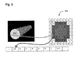
- In one embodiment of the present invention two phases are implemented - a preprocessing CPU phase and a GPU phase run from a fragment shader. In the CPU phase, each face is stored in CPU memory with a data structure for the face's loops, the face's underlying surface and other parameters including the face's uv bounding box and 3D bounding box, and other attributes needed for visualization such as color. The face parameter (uv) space is decomposed into cells, each cell can be empty (meaning that no part of the face intersects with the cell), full (meaning that the complete cell contains material of the face), or contain an edge or a vertex. For cells containing an edge or a vertex, the cell data structure stores references to one or two trimming surfaces corresponding to the one or two neighboring faces (one for edge cells, two for vertex cells) from which the loop edge or vertex originated. The cell data structure can be implemented as a regular grid over the parameter space or using a quad-tree where empty, full, edge and vertex cells are leaves of the tree. In the preprocessing step, the face representation and the cell data structure are constructed, and the cell data structure is encoded for each face in a trim state texture. The trimming surfaces are encoded in a trim surfaces texture, which is referenced by the trim state texture. An encoding of a trimming surface can, by way of non-limiting example, simply store the axis and radius of a cylinder and respective basic parameters for other types of surfaces.
- Referring now to
Fig. 3 , an embodiment's representation for a planar face that caps a cylinder is shown. InFig. 3 , theplanar face 302 of the cylinder is stored in a cell data structure 304 (in this case, a regular grid) encoded in the trim state texture. The 0-cells are empty cells, the 1-cells are inner cells, and the 2-cells are edge cells that hold references to the trimming cylinder representation in the trim surface texture. The encoded data and computation thereof will later be discussed. - The GPU phase is implemented in the fragment shader. In the fragment shader, if a ray hitting a bounding box intersects with a surface, the intersection point and uv-parameters are computed as well as the normal of the surface at the intersection point. The cell data structure is then searched for the cell with the uv-point. If the cell is an empty cell the pixel is discarded. Otherwise, the pixel color is computed using a shading method such as Phong shading or Blinn-Phong shading.
- In the next step, if the cell is full, the color is returned. If the cell is an edge cell, the ray intersection point is compared to the trimming surface, which is decoded from the trim surface texture. The pixel is discarded if the point is on the outside orientation of the surface. If the cell is a vertex cell then similarly the ray intersection point is compared to the trimming surfaces from which the vertex originated. A vertex cell can be a union cell or an intersection cell. In a union cell the pixel is discarded if the point is on the outside orientation of both surfaces. In an intersection cell the pixel is discarded if the point is outside either of the surfaces.
- An embodiment handles several surface types for ray casting and for point classification, including the common surface types used in CAD solid modeling, namely planes, cylinders, cones, torii, spheres, and NURBS surfaces. In addition, a generic mesh surface is used for any non-common surface types.
- All surfaces are parametric and represented by a uv-domain [u0; v0] × [u1; v1]. The analytic surfaces also store a local coordinate system {O; x; y; z}. (Herein bold notation denotes vector values.) Specifically, the following describes the representation of the surfaces.
- The plane equation is given by S(u,v) = ux + vy + O. Therefore, the uv-domain and local coordinate system describe the surface fully.
- The cylinder equation is given by S(u,v) = R((cos u)x + (sin u)y) + vz + O; where R is the cylinder radius and 0 ≤ u < 2π. Thus, an additional radius parameter R is passed to the fragment shader.
- The cone equation is given by S(u,v) = (R + v(tan θ))(((cos u)x + (sin u)y)) + vz + O ; where R is the radius of the intersection circle of the cone with the xy-plane. θ is the half-angle of the cone apex. The domain must satisfy 0 ≤ u < 2 π and -R(cot θ) ≤ v < ∞. The cylinder representation therefore has an additional radius parameter R and angle parameter θ, which are passed to the fragment shader.
- The sphere equation is given by S(u, v) = R(cos v)((cos u)x + (sin u)y) + R(sin v)z + O ; where R is the radius of the sphere and the domain satisfies 0 <= u < 2 π;-π/2 <= v < π/2. The sphere representation therefore has an additional radius parameter R, which is passed to the fragment shader.
- The torus equation is given by S(u,v) = (R+r(cos v))((cos u)x+(sin u)y)+r(sin v)z + O ; where R and r are the major and minor radii of the torus, respectively, and the domain satisfies 0 ≤ u < 2π; -π <= v < π.
- Unlike the analytic surfaces, a NURBS surface does not have a local coordinate system and is represented by the degree of the surface and knot vectors of the surface in u and in v, and by the control mesh of the surface in the global coordinate system. The NURBS representation is:

where m and n are the degrees of the NURBS in u and v, pij are the control points in the control mesh and Bij(u, v) are the NURBS basis functions. - CAD systems may use other surface representations instead of or in addition to analytical and NURBS surfaces. For example, to represent an offset surface, which is a procedural surface, some systems store a reference to the base surface and an offset-distance value. Such a representation cannot be represented exactly using a NURBS surface. Thus, for example, the equation for an offset surface may include a square root. Offset surface representations typically are used as black boxes that can answer queries on point and derivative evaluation at a given uv-parameter. To support less common surface representations and as a generic surface for an unsupported surface, an embodiment utilizes a surface representation comprised of a mesh with normal values at the mesh vertices; such normal values are obtained by querying the procedural surface. The meshes are regular meshes over the entire surface domain. The trimmed domain is not triangulated. The trimming of the meshes without gap artifacts is performed in the fragment shaders in the same way as is performed for other surfaces (i.e., using trimming surfaces).
- When rendering an analytic surface, a 3D box bounding the surface is rendered. The ray emanating from the viewpoint is computed with respect to the point of intersection with the box. Given the viewpoint position O in the surface local coordinate system (i.e., object space) and the ray direction vector d, the ray in the surface local coordinate system is parameterized by R (t) = O + dt. The fragment shader then computes the intersection points by finding the roots of a polynomial in t. The polynomial is constructed by plugging the linear equation of R (t) into the implicit equations of the analytical surfaces. The result is a quadratic equation for cylinders, cones, and spheres, and a quartic equation for torii. (For planes there is no need for this procedure; rather, the underlying plane is rendered directly and the shader only performs the point classification process.) Thus, the fragment shaders only need to solve a quadratic or quartic equation in order to get the intersection point (or lack thereof, in which case the pixel is discarded). Given the intersection point, the uv parameters and the normal at the intersection point is easily computed, and from those uv parameters and the normal, the shading color is computed.
- For a mesh surface, the ray casting in the shader implements a Blinn-Phong shading method, which interpolates the vertex normal values. For a NURBS surface, finding the ray-surface intersection is more complicated. A similar method to that described by Pabst et al. and Schollmeyer et al. is used. An embodiment divides the surface into Bézier patches, (which are easier to handle than bspline patches within the shaders, although bspline patches may also be used), and further subdivides the patches to sufficiently flat sub-patches. Bounding volumes of the sub-patches are then rendered using oriented bounding boxes, unlike Pabst et al. that described the use of convex hulls of the patches. The result is a bi-variate system of polynomial equations in u and v (see Pabst et al. for details) that is solved using a Newton-Raphson iteration. Once the intersection point with the underlying surface is known, the intersection point is passed to the point classification process.
- The point classification process first takes the uv-point on the face and searches for the corresponding uv cell in the cell data structure. If the cell is an empty cell, the uv-point is discarded then the process checks the next root of the ray-surface intersection polynomial for another ray intersection with the underlying surface that may be within the surface domain and inside the face. If the cell is a full cell, the pixel shade is computed using the exact normal value and the pixel is rendered. If the cell is neither full nor empty, the cell contains an edge, two intersecting edges (i.e., a vertex), or two edges that do not intersect (which may result from a coarse-grain cell structure), and the process applies a 3D point classification based on the trimming surfaces the cell references.
- In an embodiment, two cell data structures are implemented. The first cell data structure is implemented as a regular grid and stored as an RGB texture. The first value (R) stores the type of cell, and the other two values (GB) are reserved for referencing trimming surfaces in the trim surface texture. The type of cell may be empty, full, edge, union vertex, or intersection vertex.
- An empty type cell contains a uv subdomain that is not contained in the face, that is, outside the outer loop or totally inside a hole. The GB values in the empty type cell are null. A full type cell contains a uv subdomain that is completely inside the face. The GB values in the full type cell are also null. An edge type cell contains a single edge, which is a trimming curve. The G value of the edge type cell references an index in the trim surface texture, which references a representation of the trimming surface. An union vertex type cell contains two edges that are incident at a vertex. The G and B values of the union vertex type cell references indices in the trim surface texture, which in turn reference representations of the trimming surfaces.
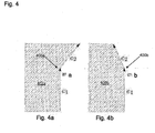
- An intersection vertex type cell is similar to the union vertex type cell; however, the classification procedure treats the union and intersection vertex type cells differently because an union vertex type cell is a result of a union boolean operation between two surfaces, whereas, the intersection vertex type cell results from an intersection between two surfaces. Thus, for an union vertex type cell, if a point is on the inner side of either trimming surface the point will be rendered. Whereas, for the intersection vertex type cell, a point is rendered only if the point is on the inner side of both trimming surfaces. The distinction between an union vertex type cell and an intersection vertex type can be determined based on the orientations of the edges around the vertex, as described with reference to
FIG. 4a and FIG. 4b . - Referring now to
FIG. 4a , va is a union vertex 400a. The edges e1 and e2 inFIG. 4a make a right turn, and therefore, the surface 402a has added material when compared to a case where the edges form a straight line.FIG. 4b shows anintersection vertex 400b denoted as vb . The edges e1 and e2 inFig. 4b make a left turn, and therefore, the surface on 402b has reduced material when compared to a case where the edges form a straight line. - A second implementation of a cell data structure is a quad-tree representation, as described in M. de Berg, O. Cheong, M. Van Kreveld, and M. Overmars; Computational Geometry, Algorithms and Applications, 3rd ed. Springer, New York; (2008), and is also stored in an RGB texture. The leaf nodes of the quad-tree store the same types of cells as in the grid cell structure previously described. However, the inner nodes of the quad-tree, which have an R value that indicates the nodes as inner nodes, refer to the first of a block of four cells that are the children of the inner node.
- In the fragment shader, given a computed uv value, a search procedure searches the cell data structure for the cell that contains the given uv point. The steps of the search procedure are dependent on the type of cell data structure. If the cell is neither empty nor full, the 3D point on the surface corresponding to the uv-point is evaluated. Then the 3D point is compared to the one or more surfaces referenced by the cell.
- As previously discussed, for each edge (i.e., each trimming curve) of a face, there exists a corresponding trimming surface referenced from cells in the cell data structure. The trimming surfaces are encoded in a floating point trim surface texture that stores the respective parameters of the surfaces. The first cell holds the surface type and the fragment shader activates a function that reads the surface from the texture based on the surface type.
- For analytic surfaces, the representations are compact, based on the parameters previously described in the discussion of surface representations. NURBS surface representations are less compact, and therefore, only the relevant Bézier sub-patches that actually intersect the face are stored in the trim surface texture. Similarly, for mesh surfaces, only the relevant triangles that actually intersect the face are stored during a preprocessing step.
- When constructing the cell data structure, the preprocessing procedure identifies for every cell whether the points of the face should lie on the positive or negative side of the surface. This information is also stored in the trim surface texture. Note that all surface representations previously described have a positive surface normal, which is defined as the direction of the cross product Su (u,v) ×Sv (u,v) at a given uv-value. Therefore, in a sufficiently close neighborhood of a surface, a point p is either on the positive or on the negative side of the surface. This can be determined when classifying a 3D point, by projecting p onto the surface, finding the closest point Sp on the surface, and comparing the vector p - Sp with the normal at Sp.
- The construction of the cell data structure is performed on the CPU, which then encodes the data structure into the trim state texture, which is then queried in the shader as previously described. The construction procedure receives as input the trimming loops, and then partitions the uv-domain of the surface into cells that contain uv subdomains.
- Referring now to
FIGS. 5a and5b , illustrations of the cell structures are shown.FIG. 5a shows a grid cell structure with a 64 X 64 grid. The grid squares are colored in two shades to distinguish between the cells.FIG. 5b shows a quad-tree cell structure where the smallest cell in the quad-tree is 0.01 of the domain width. The quad cells are colored in different shades, where leaf cells that are further from the root cell are colored in lighter shade. - The grid cell structure is a uniform grid that is laid on the uv-domain. The trimming loops are intersected with the grid and every grid cell stores a reference to the one or more trimming curves that intersect with the respective grid cell. Excluding degenerate end cases, for a sufficient resolution of the grid there are at most two edges in a cell - one if an edge passes through the cell and two if the cell contains a vertex. In rare cases, a cell may contain more than two edges or contains two edges that do not meet at a vertex, which may happen, for example, in trimming loops that are nearly tangent. In such rare cases, the grid may be reconstructed with a finer resolution. Once all the edge and vertex cells have been identified, the cells that do not hold an edge are traversed, and using a polygon point containment test, are classified as full or empty.
- The distinction between union and intersection vertices requires further computation. First, the edges are assumed to be oriented so that the material of the face is to the left of each edge, which is a common convention in CAD systems. However, an embodiment may assume that the edges are oriented so the material is to the right of each edge and have similar results. Given a vertex cell, the incoming edge is denoted by ei and the outgoing edge is denoted by eo. If the edges {ei; eo} perform a left turn then the vertex is an intersection vertex (i.e., the intersection with the surface on eo reduced material as shown in
FIG. 4b ). Otherwise, the vertex is a union vertex (i.e., the surface on e1 added material as shown inFIG. 4a ). Determining the orientation of {ei; eo} is performed by taking the tangent of the trimming curves at the endpoints and computing the cross product between them. - The quad-tree cell data structure recursively subdivides the uv-domain into subdomains until a termination criterion is satisfied (e.g., size or the overall number of subdomains). Each inner cell holds references to the inner cells's four children subdomains and also holds a list with references to all edges that intersect the respective inner cell. If the cell subdomain contains no edges, then the cell is a leaf of the quad-tree and is classified as either an empty or full leaf cell in the same way as was done for the grid cell data structure. Otherwise, the subdivision continues until only one or two edges intersect the cell or until the cell size reaches some small tolerance, which may happen in degenerate cases.
- When the cell contains only one edge, the cell is a candidate to be a leaf cell; although, having only one edge does not guarantee that the cell is a leaf. Verification is needed that the cell intersects the trimming surface only with a single component (branch). Otherwise, a point inside the cell that is outside the other branch of the surface will be treated incorrectly, for example, rendered when the point should be discarded or vice versa. Consider for example the configuration in
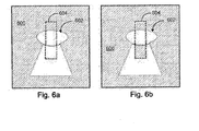
FIGS. 6a and 6b . -
FIGS. 6a and 6b show a keyhole-shaped hole in asurface 600. Atop edge 602 of the keyhole-shaped hole is an elongated arc of an ellipse on a plane. This, for example, can be a result of part of a cylinder intersecting the plane. Only points that are above the upper arc of the ellipse, as shown inFIG. 6a , should be rendered. However, if thecell 604 intersects the ellipse more than onceas in theFIGS. 6a and 6b , the point classification procedure described herein will render also those points that are outside the other branch of the ellipse (i.e., the points under the ellipse as denoted by the shaded area inFIG. 6b . Therefore, a procedure must check that the cell intersects the trimming surface with only a single connected component. -
FIGS. 6a and 6b demonstrate a classification issue that needs to be avoided and may occur when an ellipse intersects a leaf cell twice. The bold line outlining the keyhole shape is the loop of a hole in the face. The dashed rectangle is the area of a leaf cell in the quad-tree. The full ellipse has two branches in the cell where the dotted line shows the other branch.FIG. 6a illustrates the desired result where only the area above the ellipse is rendered. Whereas,FIG. 6b illustrates an undesirable result where the lower branch intersects the cell and causes the lower area to be rendered as well. - If the edge is between tangent faces, the procedure does not terminate but rather continues the subdivision until the minimum cell size is reached. Continuing the subdivision addresses difficulties tangent faces present in the point classification procedure. Similarly, if a cell contains two edges connected at a vertex, the edges must satisfy the same conditions as previously discussed. Furthermore, a vertex between tangent edges also presents difficulties in classification, and therefore in such a case, the subdivision continues until the minimum cell size is reached.
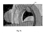
- Referring now to
FIGS. 7a through 7c , the per-pixel accuracy of an embodiment is shown.FIG. 7a shows a 3D model.FIGS. 7b and7c show zoomed-in views of the 3D model inFIG. 7a . Further,FIG. 7b illustrates a zoomed-in view using a common tessellation method; whereasFIG. 7c illustrates a ray-casting approach in one embodiment of the present invention. In particular, the curvature of therim 702 shown inFIG. 7c is much smoother than the curvature or lack thereof of therim 702 shown inFIG. 7b . - Referring now to
FIG. 8 , acomputerized modeling system 800 is shown and includes aCPU 802, acomputer monitor 804, akeyboard input device 806, amouse input device 808, and astorage device 810. TheCPU 802,computer monitor 804,keyboard 806,mouse 808, andstorage device 810 can include commonly available computer hardware devices. For example, theCPU 802 can include a Pentium-based processor. Themouse 808 may have conventional left and right buttons that the user may press to issue a command to a software program being executed by theCPU 802. As an alternative or in addition to themouse 808, thecomputerized modeling system 800 can include a pointing device such as a trackball, touch-sensitive pad, or pointing device and buttons built into thekeyboard 806. Those of ordinary skill in the art appreciate that the same results described herein with reference to a mouse device can be achieved using another available pointing device. Other appropriate computer hardware platforms are suitable as will become apparent from the discussion that follows. Such computer hardware platforms are preferably capable of operating the Microsoft® Windows® 2000, Windows XP, Windows Vista®, Windows 7, UNIX®, Linux, or Mac OS® operating systems. - Additional computer processing units and hardware devices (e.g., graphic processing units (GPUs), rapid prototyping, video, and printer devices) may be included in the
computerized modeling system 800. Furthermore, thecomputerized modeling system 800 may include network hardware and software thereby enabling wired or wireless communication to ahardware platform 812, and facilitating communication between numerous computer systems that may include a CPU and a storage system, among other computer components. - Computer-aided modeling software may be stored on the
storage device 810 and loaded into and executed by theCPU 802. The modeling software allows a user to create and modify a 3D model, and implements aspects of the invention described herein. TheCPU 802 uses thecomputer monitor 804 to display a 3D model and other aspects thereof as described. Using thekeyboard 806 and themouse 808, the user can enter and modify data associated with the 3D model. TheCPU 802 accepts and processes input from thekeyboard 806 andmouse 808. TheCPU 802 processes the input along with the data associated with the 3D model and makes corresponding and appropriate changes to that which is displayed on thecomputer monitor 804 as commanded by the modeling software. In one embodiment, the modeling software is based on a solid modeling system that may be used to construct a 3D model consisting of one or more solid and surface bodies. - The invention may be implemented in digital electronic circuitry, or in computer hardware, firmware, software, or in combinations thereof. Apparatus of the invention may be implemented in a computer program product tangibly embodied in a machine-readable storage device for execution by a programmable processor; and method steps of the invention may be performed by a programmable processor executing a program of instructions to perform functions of the invention by operating on input data and generating output. The invention may advantageously be implemented in one or more computer programs that are executable on a programmable system including at least one programmable processor coupled to receive data and instructions from, and to transmit data and instructions to, a data storage system, at least one input device, and at least one output device. Each computer program may be implemented in a high-level procedural or object-oriented programming language, or in assembly or machine language if desired; in any case, the language may be a compiled or interpreted language. In one embodiment, the present invention is implemented using the OpenGL and the GLSL shading language. Suitable processors include, by way of non-limiting example, both general and special purpose microprocessors. Generally, a processor will receive instructions and data from a read-only memory and/or a random access memory. Storage devices suitable for tangibly embodying computer program instructions and data include all forms of non-volatile memory, including by way of example semiconductor memory devices, such as EPROM, EEPROM, and flash memory devices; magnetic disks such as internal hard disks and removable disks; magneto-optical disks; and CD-ROM disks. Any of the foregoing may be supplemented by, or incorporated in, custom-designed ASICs (application-specific integrated circuits).
- High quality rendering in the manner described herein not only realizes timesaving advantages. For example, a 3D model may be rendered directly from the model's definition (e.g., analytical surface definition) rather than having to create a tessellation of the model as a pre-requisite to rendering. Other advantages include the alleviation of gap/crack artifacts, as well as the need to store large tessellations of models and to transmit the tessellations from one processing unit (e.g., a CPU) to another processing unit (e.g., GPU). Generally, the present invention is not limited by bandwidth due to the compact surface representations discussed herein, and therefore, is well-suited for client graphics applications as well as other applications. Furthermore, as GPU technology advances the fillrate-limited techniques described herein will have less of an impact on performance. CAD modeling using solid modeling techniques is widely used in the fields of engineering, industrial design, and entertainment, all of which could benefit from implementations of the present invention.
- This invention has been particularly shown and described with references to example embodiments thereof. Nevertheless, it will be understood by those skilled in the art that various modifications in form and details may be made without departing from the scope of the invention encompassed by the appended claims. For example, implementations may change the order in which operations are performed. Furthermore, depending on the needs of an implementation, particular operations described herein may be implemented as a combined operation, eliminated, added to, or otherwise rearranged. By way of non-limiting example, one embodiment may implement the cell data structure as a different structure over the parametric domain, (e.g., as a k-dimensional tree).
Claims (14)
- A computer-aided design system, comprising:a central processing unit (CPU) operatively coupled to a data storage system, the data storage system storing a three-dimensional model; anda data storage memory operatively coupled to the CPU and comprising instructions to configure the CPU to transmit data to a graphics processing unit (GPU) causing the GPU to render the three-dimensional model, free of any tessellation,characterised by:receiving a trim state texture from the CPU, wherein:the trim state texture is constructed by encoding a cell data structure comprised of a plurality of cells, created by a decomposition of a parameter space of a topological face,each cell is designated as an empty type cell, a full type cell, an edge type cell, or a vertex type cell, andwherein each of the edge type cell and the vertex type cell references representations of at least one trimming surface corresponding to one or more neighboring faces of the topological face,receiving a trim surface texture from the CPU, wherein:a trimming surface represents a neighboring face of the topological face, andthe CPU encodes the trimming surface in the trim surface texture for transmission to the GPU, wherein the trim surface texture also stores information, for each cell, whether the points of the topological face should lie on the positive or negative side of the trimming surface; andperforming a ray casting process to render the topological face using data encoded in the trim state texture and the trim surface texture to determine an intersection of a ray and a surface corresponding to the topological face, the cell data structure is then searched for the cell containing the ray intersection point:If the cell is an empty cell, the pixel is discarded, otherwise the pixel color is computed;If the cell is full, the color is returned;If the cell is an edge cell, the ray intersection point is compared to the referenced trimming surface and the pixel is discarded if the point is on the outside orientation of the trimming surface;If the cell is a vertex cell, the ray intersection point is compared to the trimming surfaces from which the vertex originated.
- The computer-aided design system as claimed in Claim 1 wherein:the empty type cell indicates that no part of the topological face intersects with a parameter space area corresponding to the empty type cell;the full type cell indicates that a total area of the full type cell contains material of the topological face; andthe edge type cell and the vertex type cell reference representations of one or more trimming surfaces corresponding to neighboring faces of the topological face.
- The computer-aided design system as claimed in Claim 1 wherein the ray casting process utilizes a fragment shader to compute the intersection of the ray and the surface corresponding to the topological face.
- The computer-aided design system as claimed in Claim 1 wherein the trim state texture references the trim surface texture that encodes the trimming surface.
- A computer-aided design system as claimed in Claim 3 wherein the trimming surfaces are represented analytically as one of a plane, a cylinder, a cone, a spline, a torus, a NURBS surface, and a generic surface.
- The computer-aided design system as claimed in Claim 1 wherein the cell data structure is implemented as one of a grid structure and a tree data structure.
- The computer-aided design system as claimed in Claim 1 further comprising: storing an underlying surface of the topological face, a uv parameter space bounding box of the topological face, and a 3D bounding box of the topological face.
- The computer-aided design system as claimed in Claim 1, wherein the plurality of cells is stored in the cell data structure and implemented as one of a grid structure and a tree data structure.
- A computer-readable data storage medium comprising instructions for causing a computer to configure a central processing unit (CPU) to transmit data to a graphics processing unit (GPU) causing the GPU to render the three-dimensional model, free of any tessellation,
characterised by:receiving a trim state texture from the CPU, wherein:the trim state texture is constructed by encoding a cell data structure comprised of a plurality of cells, created by a decomposition of a parameter space of a topological face,each cell is designated as an empty type cell, a full type cell, an edge type cell, or a vertex type cell, andwherein each of the edge type cell and the vertex type cell references representations of at least one trimming surface corresponding to one or more neighboring faces of the topological face,receiving a trim surface texture from the CPU, wherein:a trimming surface represents a neighboring face of the topological face, andthe CPU encodes the trimming surface in the trim surface texture for transmission to the GPU, wherein the trim surface texture also stores information, for each cell, whether the points of the topological face should lie on the positive or negative side of the trimming surface; andperforming a ray casting process to render the topological face using data encoded in the trim state texture and the trim surface texture to determine an intersection of a ray and a surface corresponding to the topological face, the cell data structure is then searched for the cell containing the ray intersection point:If the cell is an empty cell, the pixel is discarded, otherwise the pixel color is computed;If the cell is full, the color is returned;If the cell is an edge cell, the ray intersection point is compared to the referenced trimming surface and the pixel is discarded if the point is on the outside orientation of the trimming surface;If the cell is a vertex cell, the ray intersection point is compared to the trimming surfaces from which the vertex originated. - The computer- readable data storage medium as claimed in Claim 9 wherein the ray casting process utilizes a fragment shader that computes the intersection of the ray and a surface corresponding to the topological face.
- The computer- readable data storage medium as claimed in Claim 9 wherein the trim state texture references the trim surface texture that encodes the trimming surface.
- A computer- readable data storage medium as claimed in Claim 9 wherein the trimming surfaces are represented analytically as one of a plane, a cylinder, a cone, a spline, a torus, a NURBS surface, and a generic surface.
- The computer- readable data storage medium as claimed in Claim 9 where the CPU encodes the presence of the face as a cell type where:(i) the empty type cell indicates that no part of the topological face intersects with a uv parameter space area corresponding to the empty type cell;(ii) the full type cell indicates that a total area of the full type cell contains material of the topological face;(iii) an edge type cell stores a reference to a trimming surface corresponding to the neighboring face of the topological face; and(iv) a vertex cell stores references to at least two trimming surfaces corresponding to at least two neighboring faces of the topological face.
- A computer-implemented method for rendering a three-dimensional model, free of any tessellation, comprising the steps carried out by the computer-aided design system of any one of claims 1 to 8.
Applications Claiming Priority (2)
| Application Number | Priority Date | Filing Date | Title |
|---|---|---|---|
| US201161433001P | 2011-01-14 | 2011-01-14 | |
| PCT/US2012/021112 WO2012097175A1 (en) | 2011-01-14 | 2012-01-12 | Direct rendering of cad models on the gpu |
Publications (2)
| Publication Number | Publication Date |
|---|---|
| EP2663965A1 EP2663965A1 (en) | 2013-11-20 |
| EP2663965B1 true EP2663965B1 (en) | 2015-03-18 |
Family
ID=45582027
Family Applications (1)
| Application Number | Title | Priority Date | Filing Date |
|---|---|---|---|
| EP12703632.5A Active EP2663965B1 (en) | 2011-01-14 | 2012-01-12 | Direct rendering of cad models on the gpu |
Country Status (4)
| Country | Link |
|---|---|
| US (1) | US8982121B2 (en) |
| EP (1) | EP2663965B1 (en) |
| JP (1) | JP5916758B2 (en) |
| WO (1) | WO2012097175A1 (en) |
Families Citing this family (6)
| Publication number | Priority date | Publication date | Assignee | Title |
|---|---|---|---|---|
| US8957895B2 (en) * | 2011-09-08 | 2015-02-17 | Landmark Graphics Corporation | Systems and methods for rendering 2D grid data |
| US9305370B2 (en) | 2013-07-31 | 2016-04-05 | Qualcomm Incorporated | Graphical rendering with implicit surfaces |
| US9449424B2 (en) * | 2013-09-12 | 2016-09-20 | Analytical Graphics Inc. | Visualization of field of view obstruction by an ellipsoid |
| US9984496B1 (en) | 2016-08-23 | 2018-05-29 | Bentley Systems, Incorporated | Technique for compact and accurate encoding trim geometry for application in a graphical processing unit |
| US11238649B2 (en) * | 2019-11-26 | 2022-02-01 | Nature Simulation Systems Inc. | Method and system for hybrid modeling using geometric facets |
| CN115795939B (en) * | 2022-11-03 | 2023-06-13 | 天津大学 | Two-dimensional flood process multi-GPU simulation method based on unstructured grid |
Family Cites Families (5)
| Publication number | Priority date | Publication date | Assignee | Title |
|---|---|---|---|---|
| US7079990B2 (en) * | 2001-02-08 | 2006-07-18 | Solidworks Corporation | Automated connections of computer-aided design components |
| US20070018988A1 (en) * | 2005-07-20 | 2007-01-25 | Michael Guthe | Method and applications for rasterization of non-simple polygons and curved boundary representations |
| JP4783100B2 (en) * | 2005-09-12 | 2011-09-28 | 独立行政法人理化学研究所 | Method of converting boundary data into in-cell shape data and its conversion program |
| US8446410B2 (en) * | 2006-05-11 | 2013-05-21 | Anatomage Inc. | Apparatus for generating volumetric image and matching color textured external surface |
| US7688318B2 (en) * | 2007-02-02 | 2010-03-30 | Dassault Systemes Solidworks Corporation | Reusable data constructs for a modeling system |
-
2012
- 2012-01-12 JP JP2013549548A patent/JP5916758B2/en active Active
- 2012-01-12 EP EP12703632.5A patent/EP2663965B1/en active Active
- 2012-01-12 WO PCT/US2012/021112 patent/WO2012097175A1/en active Application Filing
- 2012-01-12 US US13/349,421 patent/US8982121B2/en active Active
Also Published As
| Publication number | Publication date |
|---|---|
| US20120182297A1 (en) | 2012-07-19 |
| JP5916758B2 (en) | 2016-05-11 |
| EP2663965A1 (en) | 2013-11-20 |
| US8982121B2 (en) | 2015-03-17 |
| WO2012097175A1 (en) | 2012-07-19 |
| JP2014507027A (en) | 2014-03-20 |
Similar Documents
| Publication | Publication Date | Title |
|---|---|---|
| Loop et al. | Approximating subdivision surfaces with gregory patches for hardware tessellation | |
| US7561156B2 (en) | Adaptive quadtree-based scalable surface rendering | |
| EP2663965B1 (en) | Direct rendering of cad models on the gpu | |
| US5377320A (en) | Method and apparatus for the rendering of trimmed nurb surfaces | |
| US20070018988A1 (en) | Method and applications for rasterization of non-simple polygons and curved boundary representations | |
| EP3379495B1 (en) | Seamless fracture in an animation production pipeline | |
| CN111581776B (en) | Iso-geometric analysis method based on geometric reconstruction model | |
| Pabst et al. | Ray casting of trimmed NURBS surfaces on the GPU | |
| US8717356B2 (en) | Display processing method and apparatus | |
| Hanniel et al. | Direct rendering of solid CAD models on the GPU | |
| Schollmeyer et al. | Direct trimming of NURBS surfaces on the GPU | |
| CN109983509B (en) | Instant Boolean operation method using geometric surface | |
| Hsieh et al. | A simple GPU-based approach for 3D Voronoi diagram construction and visualization | |
| Li et al. | Efficient ray casting polygonized isosurface of binary volumes | |
| Trettner et al. | Sampling from Quadric‐Based CSG Surfaces | |
| Flórez Díaz | Improvements in the ray tracing of implicit surfaces based on interval arithmetic | |
| Ivo et al. | Improved silhouette rendering and detection of splat-based models | |
| Pal | Fast freeform hybrid reconstruction with manual mesh segmentation | |
| Lin et al. | A feature-adaptive subdivision method for real-time 3D reconstruction of repeated topology surfaces | |
| Shakaev et al. | View-Dependent Level of Detail for Real-Time Rendering of Large Isosurfaces | |
| Rueda et al. | GPU-based rendering of curved polygons using simplicial coverings | |
| Morgan et al. | A hybrid hierarchical procedure for composing trivariate NURBS solids | |
| Hui et al. | Tetrahedra based adaptive polygonization of implicit surface patches | |
| Cohen et al. | Generating a smooth voxel-based model from an irregular polygon mesh | |
| Barnard | Applying tessellation to clipmap terrain rendering |
Legal Events
| Date | Code | Title | Description |
|---|---|---|---|
| PUAI | Public reference made under article 153(3) epc to a published international application that has entered the european phase |
Free format text: ORIGINAL CODE: 0009012 |
|
| 17P | Request for examination filed |
Effective date: 20130814 |
|
| AK | Designated contracting states |
Kind code of ref document: A1 Designated state(s): AL AT BE BG CH CY CZ DE DK EE ES FI FR GB GR HR HU IE IS IT LI LT LU LV MC MK MT NL NO PL PT RO RS SE SI SK SM TR |
|
| DAX | Request for extension of the european patent (deleted) | ||
| REG | Reference to a national code |
Ref country code: DE Ref legal event code: R079 Ref document number: 602012005985 Country of ref document: DE Free format text: PREVIOUS MAIN CLASS: G06T0015000000 Ipc: G06T0015060000 |
|
| GRAP | Despatch of communication of intention to grant a patent |
Free format text: ORIGINAL CODE: EPIDOSNIGR1 |
|
| RIC1 | Information provided on ipc code assigned before grant |
Ipc: G06T 17/10 20060101ALI20140509BHEP Ipc: G06T 15/06 20110101AFI20140509BHEP |
|
| INTG | Intention to grant announced |
Effective date: 20140526 |
|
| GRAS | Grant fee paid |
Free format text: ORIGINAL CODE: EPIDOSNIGR3 |
|
| GRAP | Despatch of communication of intention to grant a patent |
Free format text: ORIGINAL CODE: EPIDOSNIGR1 |
|
| INTG | Intention to grant announced |
Effective date: 20141024 |
|
| GRAA | (expected) grant |
Free format text: ORIGINAL CODE: 0009210 |
|
| AK | Designated contracting states |
Kind code of ref document: B1 Designated state(s): AL AT BE BG CH CY CZ DE DK EE ES FI FR GB GR HR HU IE IS IT LI LT LU LV MC MK MT NL NO PL PT RO RS SE SI SK SM TR |
|
| REG | Reference to a national code |
Ref country code: GB Ref legal event code: FG4D |
|
| REG | Reference to a national code |
Ref country code: CH Ref legal event code: EP |
|
| REG | Reference to a national code |
Ref country code: IE Ref legal event code: FG4D |
|
| REG | Reference to a national code |
Ref country code: AT Ref legal event code: REF Ref document number: 716995 Country of ref document: AT Kind code of ref document: T Effective date: 20150415 |
|
| REG | Reference to a national code |
Ref country code: DE Ref legal event code: R096 Ref document number: 602012005985 Country of ref document: DE Effective date: 20150430 |
|
| REG | Reference to a national code |
Ref country code: NL Ref legal event code: VDEP Effective date: 20150318 |
|
| REG | Reference to a national code |
Ref country code: NL Ref legal event code: VDEP Effective date: 20150318 |
|
| PG25 | Lapsed in a contracting state [announced via postgrant information from national office to epo] |
Ref country code: FI Free format text: LAPSE BECAUSE OF FAILURE TO SUBMIT A TRANSLATION OF THE DESCRIPTION OR TO PAY THE FEE WITHIN THE PRESCRIBED TIME-LIMIT Effective date: 20150318 Ref country code: SE Free format text: LAPSE BECAUSE OF FAILURE TO SUBMIT A TRANSLATION OF THE DESCRIPTION OR TO PAY THE FEE WITHIN THE PRESCRIBED TIME-LIMIT Effective date: 20150318 Ref country code: LT Free format text: LAPSE BECAUSE OF FAILURE TO SUBMIT A TRANSLATION OF THE DESCRIPTION OR TO PAY THE FEE WITHIN THE PRESCRIBED TIME-LIMIT Effective date: 20150318 Ref country code: HR Free format text: LAPSE BECAUSE OF FAILURE TO SUBMIT A TRANSLATION OF THE DESCRIPTION OR TO PAY THE FEE WITHIN THE PRESCRIBED TIME-LIMIT Effective date: 20150318 Ref country code: NO Free format text: LAPSE BECAUSE OF FAILURE TO SUBMIT A TRANSLATION OF THE DESCRIPTION OR TO PAY THE FEE WITHIN THE PRESCRIBED TIME-LIMIT Effective date: 20150618 |
|
| REG | Reference to a national code |
Ref country code: AT Ref legal event code: MK05 Ref document number: 716995 Country of ref document: AT Kind code of ref document: T Effective date: 20150318 |
|
| REG | Reference to a national code |
Ref country code: LT Ref legal event code: MG4D |
|
| PG25 | Lapsed in a contracting state [announced via postgrant information from national office to epo] |
Ref country code: RS Free format text: LAPSE BECAUSE OF FAILURE TO SUBMIT A TRANSLATION OF THE DESCRIPTION OR TO PAY THE FEE WITHIN THE PRESCRIBED TIME-LIMIT Effective date: 20150318 Ref country code: GR Free format text: LAPSE BECAUSE OF FAILURE TO SUBMIT A TRANSLATION OF THE DESCRIPTION OR TO PAY THE FEE WITHIN THE PRESCRIBED TIME-LIMIT Effective date: 20150619 Ref country code: LV Free format text: LAPSE BECAUSE OF FAILURE TO SUBMIT A TRANSLATION OF THE DESCRIPTION OR TO PAY THE FEE WITHIN THE PRESCRIBED TIME-LIMIT Effective date: 20150318 |
|
| PG25 | Lapsed in a contracting state [announced via postgrant information from national office to epo] |
Ref country code: NL Free format text: LAPSE BECAUSE OF FAILURE TO SUBMIT A TRANSLATION OF THE DESCRIPTION OR TO PAY THE FEE WITHIN THE PRESCRIBED TIME-LIMIT Effective date: 20150318 |
|
| PG25 | Lapsed in a contracting state [announced via postgrant information from national office to epo] |
Ref country code: ES Free format text: LAPSE BECAUSE OF FAILURE TO SUBMIT A TRANSLATION OF THE DESCRIPTION OR TO PAY THE FEE WITHIN THE PRESCRIBED TIME-LIMIT Effective date: 20150318 Ref country code: PT Free format text: LAPSE BECAUSE OF FAILURE TO SUBMIT A TRANSLATION OF THE DESCRIPTION OR TO PAY THE FEE WITHIN THE PRESCRIBED TIME-LIMIT Effective date: 20150720 Ref country code: EE Free format text: LAPSE BECAUSE OF FAILURE TO SUBMIT A TRANSLATION OF THE DESCRIPTION OR TO PAY THE FEE WITHIN THE PRESCRIBED TIME-LIMIT Effective date: 20150318 Ref country code: CZ Free format text: LAPSE BECAUSE OF FAILURE TO SUBMIT A TRANSLATION OF THE DESCRIPTION OR TO PAY THE FEE WITHIN THE PRESCRIBED TIME-LIMIT Effective date: 20150318 Ref country code: RO Free format text: LAPSE BECAUSE OF FAILURE TO SUBMIT A TRANSLATION OF THE DESCRIPTION OR TO PAY THE FEE WITHIN THE PRESCRIBED TIME-LIMIT Effective date: 20150318 Ref country code: SK Free format text: LAPSE BECAUSE OF FAILURE TO SUBMIT A TRANSLATION OF THE DESCRIPTION OR TO PAY THE FEE WITHIN THE PRESCRIBED TIME-LIMIT Effective date: 20150318 |
|
| PG25 | Lapsed in a contracting state [announced via postgrant information from national office to epo] |
Ref country code: AT Free format text: LAPSE BECAUSE OF FAILURE TO SUBMIT A TRANSLATION OF THE DESCRIPTION OR TO PAY THE FEE WITHIN THE PRESCRIBED TIME-LIMIT Effective date: 20150318 Ref country code: IS Free format text: LAPSE BECAUSE OF FAILURE TO SUBMIT A TRANSLATION OF THE DESCRIPTION OR TO PAY THE FEE WITHIN THE PRESCRIBED TIME-LIMIT Effective date: 20150718 Ref country code: PL Free format text: LAPSE BECAUSE OF FAILURE TO SUBMIT A TRANSLATION OF THE DESCRIPTION OR TO PAY THE FEE WITHIN THE PRESCRIBED TIME-LIMIT Effective date: 20150318 |
|
| REG | Reference to a national code |
Ref country code: DE Ref legal event code: R097 Ref document number: 602012005985 Country of ref document: DE |
|
| PG25 | Lapsed in a contracting state [announced via postgrant information from national office to epo] |
Ref country code: IT Free format text: LAPSE BECAUSE OF FAILURE TO SUBMIT A TRANSLATION OF THE DESCRIPTION OR TO PAY THE FEE WITHIN THE PRESCRIBED TIME-LIMIT Effective date: 20150318 |
|
| REG | Reference to a national code |
Ref country code: FR Ref legal event code: PLFP Year of fee payment: 5 |
|
| PLBE | No opposition filed within time limit |
Free format text: ORIGINAL CODE: 0009261 |
|
| STAA | Information on the status of an ep patent application or granted ep patent |
Free format text: STATUS: NO OPPOSITION FILED WITHIN TIME LIMIT |
|
| PG25 | Lapsed in a contracting state [announced via postgrant information from national office to epo] |
Ref country code: DK Free format text: LAPSE BECAUSE OF FAILURE TO SUBMIT A TRANSLATION OF THE DESCRIPTION OR TO PAY THE FEE WITHIN THE PRESCRIBED TIME-LIMIT Effective date: 20150318 |
|
| 26N | No opposition filed |
Effective date: 20151221 |
|
| PG25 | Lapsed in a contracting state [announced via postgrant information from national office to epo] |
Ref country code: SI Free format text: LAPSE BECAUSE OF FAILURE TO SUBMIT A TRANSLATION OF THE DESCRIPTION OR TO PAY THE FEE WITHIN THE PRESCRIBED TIME-LIMIT Effective date: 20150318 |
|
| PG25 | Lapsed in a contracting state [announced via postgrant information from national office to epo] |
Ref country code: BE Free format text: LAPSE BECAUSE OF NON-PAYMENT OF DUE FEES Effective date: 20160131 |
|
| PG25 | Lapsed in a contracting state [announced via postgrant information from national office to epo] |
Ref country code: LU Free format text: LAPSE BECAUSE OF FAILURE TO SUBMIT A TRANSLATION OF THE DESCRIPTION OR TO PAY THE FEE WITHIN THE PRESCRIBED TIME-LIMIT Effective date: 20160112 Ref country code: BE Free format text: LAPSE BECAUSE OF FAILURE TO SUBMIT A TRANSLATION OF THE DESCRIPTION OR TO PAY THE FEE WITHIN THE PRESCRIBED TIME-LIMIT Effective date: 20150318 |
|
| REG | Reference to a national code |
Ref country code: CH Ref legal event code: PL |
|
| PG25 | Lapsed in a contracting state [announced via postgrant information from national office to epo] |
Ref country code: MC Free format text: LAPSE BECAUSE OF FAILURE TO SUBMIT A TRANSLATION OF THE DESCRIPTION OR TO PAY THE FEE WITHIN THE PRESCRIBED TIME-LIMIT Effective date: 20150318 |
|
| PG25 | Lapsed in a contracting state [announced via postgrant information from national office to epo] |
Ref country code: LI Free format text: LAPSE BECAUSE OF NON-PAYMENT OF DUE FEES Effective date: 20160131 Ref country code: CH Free format text: LAPSE BECAUSE OF NON-PAYMENT OF DUE FEES Effective date: 20160131 |
|
| REG | Reference to a national code |
Ref country code: IE Ref legal event code: MM4A |
|
| REG | Reference to a national code |
Ref country code: FR Ref legal event code: PLFP Year of fee payment: 6 |
|
| PG25 | Lapsed in a contracting state [announced via postgrant information from national office to epo] |
Ref country code: IE Free format text: LAPSE BECAUSE OF NON-PAYMENT OF DUE FEES Effective date: 20160112 |
|
| PG25 | Lapsed in a contracting state [announced via postgrant information from national office to epo] |
Ref country code: MT Free format text: LAPSE BECAUSE OF FAILURE TO SUBMIT A TRANSLATION OF THE DESCRIPTION OR TO PAY THE FEE WITHIN THE PRESCRIBED TIME-LIMIT Effective date: 20150318 |
|
| REG | Reference to a national code |
Ref country code: FR Ref legal event code: PLFP Year of fee payment: 7 |
|
| PG25 | Lapsed in a contracting state [announced via postgrant information from national office to epo] |
Ref country code: HU Free format text: LAPSE BECAUSE OF FAILURE TO SUBMIT A TRANSLATION OF THE DESCRIPTION OR TO PAY THE FEE WITHIN THE PRESCRIBED TIME-LIMIT; INVALID AB INITIO Effective date: 20120112 Ref country code: CY Free format text: LAPSE BECAUSE OF FAILURE TO SUBMIT A TRANSLATION OF THE DESCRIPTION OR TO PAY THE FEE WITHIN THE PRESCRIBED TIME-LIMIT Effective date: 20150318 Ref country code: SM Free format text: LAPSE BECAUSE OF FAILURE TO SUBMIT A TRANSLATION OF THE DESCRIPTION OR TO PAY THE FEE WITHIN THE PRESCRIBED TIME-LIMIT Effective date: 20150318 |
|
| PG25 | Lapsed in a contracting state [announced via postgrant information from national office to epo] |
Ref country code: MK Free format text: LAPSE BECAUSE OF FAILURE TO SUBMIT A TRANSLATION OF THE DESCRIPTION OR TO PAY THE FEE WITHIN THE PRESCRIBED TIME-LIMIT Effective date: 20150318 Ref country code: TR Free format text: LAPSE BECAUSE OF FAILURE TO SUBMIT A TRANSLATION OF THE DESCRIPTION OR TO PAY THE FEE WITHIN THE PRESCRIBED TIME-LIMIT Effective date: 20150318 Ref country code: MT Free format text: LAPSE BECAUSE OF FAILURE TO SUBMIT A TRANSLATION OF THE DESCRIPTION OR TO PAY THE FEE WITHIN THE PRESCRIBED TIME-LIMIT Effective date: 20160131 |
|
| PG25 | Lapsed in a contracting state [announced via postgrant information from national office to epo] |
Ref country code: BG Free format text: LAPSE BECAUSE OF FAILURE TO SUBMIT A TRANSLATION OF THE DESCRIPTION OR TO PAY THE FEE WITHIN THE PRESCRIBED TIME-LIMIT Effective date: 20150318 |
|
| PG25 | Lapsed in a contracting state [announced via postgrant information from national office to epo] |
Ref country code: AL Free format text: LAPSE BECAUSE OF FAILURE TO SUBMIT A TRANSLATION OF THE DESCRIPTION OR TO PAY THE FEE WITHIN THE PRESCRIBED TIME-LIMIT Effective date: 20150318 |
|
| PGFP | Annual fee paid to national office [announced via postgrant information from national office to epo] |
Ref country code: FR Payment date: 20230124 Year of fee payment: 12 |
|
| PGFP | Annual fee paid to national office [announced via postgrant information from national office to epo] |
Ref country code: GB Payment date: 20230119 Year of fee payment: 12 Ref country code: DE Payment date: 20230123 Year of fee payment: 12 |
|
| P01 | Opt-out of the competence of the unified patent court (upc) registered |
Effective date: 20230527 |