EP2663024B1 - Communication device, communication method, recording medium, and program - Google Patents
Communication device, communication method, recording medium, and program Download PDFInfo
- Publication number
- EP2663024B1 EP2663024B1 EP13179770.6A EP13179770A EP2663024B1 EP 2663024 B1 EP2663024 B1 EP 2663024B1 EP 13179770 A EP13179770 A EP 13179770A EP 2663024 B1 EP2663024 B1 EP 2663024B1
- Authority
- EP
- European Patent Office
- Prior art keywords
- data
- receiving apparatus
- shared
- acknowledgment
- tcp
- Prior art date
- Legal status (The legal status is an assumption and is not a legal conclusion. Google has not performed a legal analysis and makes no representation as to the accuracy of the status listed.)
- Expired - Lifetime
Links
- 238000004891 communication Methods 0.000 title claims description 76
- 238000000034 method Methods 0.000 title claims description 47
- 230000005540 biological transmission Effects 0.000 claims description 44
- 230000004044 response Effects 0.000 claims description 26
- 230000010365 information processing Effects 0.000 claims 7
- 238000004590 computer program Methods 0.000 claims 3
- 108700028516 Lan-7 Proteins 0.000 description 4
- 230000003287 optical effect Effects 0.000 description 4
- 239000004065 semiconductor Substances 0.000 description 2
- 238000012795 verification Methods 0.000 description 2
- 230000003247 decreasing effect Effects 0.000 description 1
- 238000010586 diagram Methods 0.000 description 1
- 238000005259 measurement Methods 0.000 description 1
- 230000006855 networking Effects 0.000 description 1
- 238000012545 processing Methods 0.000 description 1
- 238000012360 testing method Methods 0.000 description 1
Images


Classifications
-
- H—ELECTRICITY
- H04—ELECTRIC COMMUNICATION TECHNIQUE
- H04L—TRANSMISSION OF DIGITAL INFORMATION, e.g. TELEGRAPHIC COMMUNICATION
- H04L43/00—Arrangements for monitoring or testing data switching networks
- H04L43/08—Monitoring or testing based on specific metrics, e.g. QoS, energy consumption or environmental parameters
- H04L43/0852—Delays
- H04L43/0864—Round trip delays
-
- G—PHYSICS
- G06—COMPUTING; CALCULATING OR COUNTING
- G06F—ELECTRIC DIGITAL DATA PROCESSING
- G06F21/00—Security arrangements for protecting computers, components thereof, programs or data against unauthorised activity
- G06F21/10—Protecting distributed programs or content, e.g. vending or licensing of copyrighted material ; Digital rights management [DRM]
-
- H—ELECTRICITY
- H04—ELECTRIC COMMUNICATION TECHNIQUE
- H04L—TRANSMISSION OF DIGITAL INFORMATION, e.g. TELEGRAPHIC COMMUNICATION
- H04L43/00—Arrangements for monitoring or testing data switching networks
- H04L43/10—Active monitoring, e.g. heartbeat, ping or trace-route
-
- H—ELECTRICITY
- H04—ELECTRIC COMMUNICATION TECHNIQUE
- H04L—TRANSMISSION OF DIGITAL INFORMATION, e.g. TELEGRAPHIC COMMUNICATION
- H04L43/00—Arrangements for monitoring or testing data switching networks
- H04L43/50—Testing arrangements
-
- H—ELECTRICITY
- H04—ELECTRIC COMMUNICATION TECHNIQUE
- H04L—TRANSMISSION OF DIGITAL INFORMATION, e.g. TELEGRAPHIC COMMUNICATION
- H04L63/00—Network architectures or network communication protocols for network security
- H04L63/08—Network architectures or network communication protocols for network security for authentication of entities
-
- H—ELECTRICITY
- H04—ELECTRIC COMMUNICATION TECHNIQUE
- H04L—TRANSMISSION OF DIGITAL INFORMATION, e.g. TELEGRAPHIC COMMUNICATION
- H04L63/00—Network architectures or network communication protocols for network security
- H04L63/10—Network architectures or network communication protocols for network security for controlling access to devices or network resources
-
- H—ELECTRICITY
- H04—ELECTRIC COMMUNICATION TECHNIQUE
- H04L—TRANSMISSION OF DIGITAL INFORMATION, e.g. TELEGRAPHIC COMMUNICATION
- H04L69/00—Network arrangements, protocols or services independent of the application payload and not provided for in the other groups of this subclass
- H04L69/16—Implementation or adaptation of Internet protocol [IP], of transmission control protocol [TCP] or of user datagram protocol [UDP]
- H04L69/163—In-band adaptation of TCP data exchange; In-band control procedures
-
- H—ELECTRICITY
- H04—ELECTRIC COMMUNICATION TECHNIQUE
- H04W—WIRELESS COMMUNICATION NETWORKS
- H04W24/00—Supervisory, monitoring or testing arrangements
- H04W24/06—Testing, supervising or monitoring using simulated traffic
-
- H—ELECTRICITY
- H04—ELECTRIC COMMUNICATION TECHNIQUE
- H04L—TRANSMISSION OF DIGITAL INFORMATION, e.g. TELEGRAPHIC COMMUNICATION
- H04L12/00—Data switching networks
- H04L12/54—Store-and-forward switching systems
- H04L12/56—Packet switching systems
- H04L12/5601—Transfer mode dependent, e.g. ATM
- H04L2012/5603—Access techniques
Definitions
- the present invention relates to a telecommunications apparatus and a method, a system, a storage medium, and a program and, in particular, to a telecommunications apparatus and a method, a system, a storage medium, and a program suitable for determining whether data communication takes place across a WAN such as the Internet or on a LAN in a house.
- a WAN such as the Internet
- a LAN in a house
- some music download services limit the storage medium that stores the downloaded audio data to a storage medium having predetermined protection against being copied.
- the encrypted content data are transferred after authentication to prevent the content data from being transferred to an unauthorized device.
- IP protocols which are commonly used for WAN communication.
- One possible solution is to limit the area of communication to a LAN when distributing the content data over an IP protocol.
- To limit the communication of content data within the LAN it must be determined whether or not the other side communicating the content data is located on a LAN or a WAN. A method for such a determination, however, has not yet been established.
- EP 0999673 A2 describes a method and apparatus for determining the reachability of a remote computer from a local computer through a secured communications link through the Internet, in which a protected keepalive message is transmitted by the local computer to the remote computer in the event that the communications link has been idle for a period of time.
- GB 2356536 A describes a method for carrying out real-time backup communication of IP communications, in which if the time interval between sending and receiving an echo test signal exceeds a predetermined allowed time interval then the quality of real time communication cannot be assured and performance is deemed unsatisfactory.
- US 5550887 describes a method of measuring the distance and the positional relationship between the equipments on a LAN, in which a first equipment transmits a request packet to each of the other equipments at a predetermined interval of time. When each of the other equipments receives the request packet, it supplies the response packet to the first equipment. The first equipment calculates the distance between the first equipment and each of the other equipments on the basis of the time at which the request packet has been transmitted and the time at which the response packet has been received, and stores the calculated distance in the network structure information table NWT. Since the packet transmission speed changes in accordance with the traffic volume, the calculated distance is compared with the distance stored in the network structure information table NWT, and only when the calculated distance is shorter, it is stored in the network structure information table NWT.
- WO 2004/030311 describes a system and method which determines the proximity of the target node to the source node from the time required to communicate messages within the node-verification protocol.
- the node-verification protocol includes a query-response sequence, wherein the source node communicates a query to the target node, and the target node communicates a corresponding response to the source node.
- the target node is configured to communicate two responses to the query: a first response that is transmitted immediately upon receipt of the query, and a second response based on the contents of the query.
- the communication time is determined based on the time duration between the transmission of the query and receipt of the first response at the source node and the second response is compared for correspondence to the query, to verify the authenticity of the target node.
- a telecommunications apparatus includes transmission means for transmitting a predetermined number of check packets, receiving means for receiving transmitted check packets, information generating means for generating acknowledgement information and sending back the acknowledgement information after receiving the predetermined number of check packets by the receiving means, acquiring means for acquiring the acknowledgement information sent back from another apparatus for communication, measuring means for measuring an elapsed time from the transmission of the predetermined number of check packets by the transmission means to the reception of the acknowledgement information by the acquiring means, and determination means for determining, based on a measuring result of the measuring means, whether or not another apparatus for communication is located on the same first network as itself or across a second network different from the first network.
- the determination means may determine that another apparatus for communication is located on the first network if the elapsed time measured by the measuring means is smaller than a predetermined threshold value or may determine that another apparatus for communication is located across the second network if the elapsed time measured by the measuring means is greater than or equal to the predetermined threshold value.
- the first network may be a local area network (LAN) and the second network may be a wide area network (WAN).
- LAN local area network
- WAN wide area network
- the communication means and the receiving means may work with a TCP protocol or a UDP protocol.
- a telecommunications method includes a step of transmitting a predetermined number of check packets, a step of receiving transmitted check packets, a step of generating acknowledgement information and sending back the acknowledgement information after receiving the predetermined number of check packets in the receiving step, a step of acquiring the acknowledgement information sent back from another apparatus for communication, a step of measuring an elapsed time from the transmission of the predetermined number of check packets in the transmitting step to the reception of the acknowledgement information in the acquiring step, and a step of determining, based on a measuring result in the measuring step, whether or not another apparatus for communication is located on the same first network as itself or across a second network different from the first network.
- a storage medium includes a program including a step of transmitting a predetermined number of check packets, a step of receiving transmitted check packets, a step of generating acknowledgement information and sending back the acknowledgement information after receiving the predetermined number of check packets in the receiving step, a step of acquiring the acknowledgement information sent back from another apparatus for communication, a step of measuring an elapsed time from the transmission of the predetermined number of check packets in the transmitting step to the reception of the acknowledgement information in the acquiring step, and a step of determining, based on a measuring result in the measuring step, whether or not another apparatus for communication is located on the same first network as itself or across a second network different from the first network.
- a program allows a computer to execute a step of transmitting a predetermined number of check packets, a step of receiving transmitted check packets, a step of generating acknowledgement information and sending back the acknowledgement information after receiving the predetermined number of check packets in the receiving step, a step of acquiring the acknowledgement information sent back from another apparatus for communication, a step of measuring an elapsed time from the transmission of the predetermined number of check packets in the transmitting step to the reception of the acknowledgement information in the acquiring step, and a step of determining, based on a measuring result in the measuring step, whether or not another apparatus for communication is located on the same first network as itself or across a second network different from the first network.
- a predetermined number of check packets are transmitted to another apparatus for communication, and acknowledgement information sent back from the apparatus is received.
- acknowledgement information sent back from the apparatus is received.
- an elapsed time from the transmission of the predetermined number of check packets to the reception of the acknowledgement information is measured. The result of the measurement is used to determine whether the apparatus for communication is located on the same first network as itself or across a second network different from the first network.
- Fig. 1 shows a configuration of a telecommunications system including a LAN having personal computers and AV devices according to an embodiment of the present invention.
- LANs 1 and 7, and a server 8 are connected to one another across a WAN 6, such as the Internet.
- the LAN 1 includes personal computers (PCs) 3 and 4, and an AV device 5, all connected via a switching hub 2.
- the LAN 1 is, for example, used for communication among specific individuals or a family in a house.
- the switching hub 2 is connected to the personal computers 3 and 4 and the AV device 5 via a high-speed interface, such as Ethernet (R) 100BASE-TX. Data communication can take place among the personal computers 3 and 4 and the AV device 5 at a rate of about 100 Mbps with a sufficiently low error rate.
- the personal computers (PCs) 3 and 4 and the AV device 5 can communicate with the LAN 7 or the server 8 via the switching hub 2 and the WAN 6.
- the personal computer (PC) 3 upon transmission of content data, can determine whether or not the other side communicating the content data is located on the LAN 1, for example, the personal computer 4 or is located across the WAN 6, for example, the server 8.
- the personal computer 4 and the AV device 5 upon the transmission of content data, can determine whether the other side communicating the content data is located on the LAN 1, for example, the personal computer 3 or is located across the WAN 6, for example, the server 8.
- the LAN 7 has the same configuration as that of the LAN 1, however, it is managed by a different user from the LAN 1.
- the server 8 is managed by a different user from the LANs 1 and 7.
- Fig. 2 shows a configuration of the personal computer 3.
- the personal computer 3 incorporates a central processing unit (CPU) 21, to which an I/O interface 25 is connected via a bus 24.
- a read only memory (ROM) 22 and a random access memory (RAM) 23 are connected to the bus 24.
- the I/O interface 25 includes an input unit 26 composed of I/O devices, such as a keyboard and a mouse, by which a user enters operation commands, an output unit 27 which outputs video signals to display operation screens on a display unit, a storage unit 28 which includes a hard disk drive to store programs and other various types of data, and a communication unit 29 which includes an Ethernet (R) interface to transmit and receive data via a 100BASE-TX cable connected to the switching hub 2.
- I/O interface 25 includes an input unit 26 composed of I/O devices, such as a keyboard and a mouse, by which a user enters operation commands, an output unit 27 which outputs video signals to display operation screens on a display unit, a storage unit 28 which includes a hard disk drive to store programs and other various types of data, and a communication unit 29 which includes an Ethernet (R) interface to transmit and receive data via a 100BASE-TX cable connected to the switching hub 2.
- R Ethernet
- the communication unit 29 may include a universal serial bus (USB), or a high-speed interface, such as an Institute of Electrical and Electronics Engineers (IEEE) 1394.
- USB universal serial bus
- IEEE Institute of Electrical and Electronics Engineers
- a drive 30 which reads and writes data to and from storage media, such as a magnetic disk 31, an optical disk 32, an optical magnetic disk 33, and a semiconductor memory 34, is connected to the I/O interface 25.
- the CPU 21 performs various types of processes, which will be described below, under the control of a program in the ROM 22 or in the RAM 23.
- the program is read from the magnetic disk 31, the optical disk 32, the optical magnetic disk 33, or the semiconductor memory 34, is stored in the storage unit 28, and is then loaded from the storage unit 28 to the RAM 23.
- the RAM 23 also stores data required for the CPU 21 to perform the various types of processes.
- Fig. 3 shows a first configuration of a functional block achieved by the communication unit 29 in response to controls of the CPU 21.
- a control unit 41 controls a transmitter-receiver unit 43 which transmits and receives data over the user datagram protocol (UDP), which is one of the communication protocols.
- the control unit 41 accesses a register 42. Before the transmitter-receiver unit 43 transmits content data in response to the control of the control unit 41, it transmits a predetermined number of check packets to determine whether the other side communicating the content data is located on the LAN 1 or across the WAN 6.
- UDP user datagram protocol
- Fig. 4 shows an example of the check packet.
- this check packet has a payload to store a counter value generated by the control unit 41.
- the PC 4 and the AV device 5 have the same hardware or software functional block as that of the communication unit 29 shown in Fig. 3 .
- various types of apparatuses on the LAN 7 and the server 8 have the same functional block.
- the UDP protocol defines that, in the case of a communication error, a packet that is not transmitted correctly is discarded and is not retransmitted. Using this characteristic, whether or not the other side communicating the content data is located on the LAN 1 or across the WAN 6 can be determined.
- the switching hub 2 transmits all packets to the peer without changing the sequence of the packets, whereas in a high-speed communication with a peer across the WAN 6, a communication error occurs due to a wide area networking and the UDP protocol discards the erroneous packet. Therefore, the peer does not receive some packets or receives the packets in a different order from the transmission order. This is used to determine whether the other side communicating the content data is located on the LAN 1 or across the WAN 6.
- a transmission process in the first configuration of the communication unit 29 shown in Fig. 3 will now be described with reference to the flow chart in Fig. 5 .
- This transmission process determines whether the other side communicating the content data is located on the LAN 1 or across the WAN 6 before the communication of content data takes place.
- step S1 the control unit 41 assigns an initial value A to a value in a counter therein (counter value).
- step S2 the control unit 41 increments the counter by a constant value X, then outputs the counter value to the transmitter-receiver unit 43.
- step S3 the transmitter-receiver unit 43, in response to the control of the control unit 41, writes the counter value from the control unit 41 into the payload of a check packet and then transmits it to the other side communicating the content data.
- step S4 the control unit 41 determines whether the transmitter-receiver unit 43 transmits all the predetermined number of check packets. If all the predetermined number of check packets is not yet transmitted, the process returns to step S2 and the subsequent processes are repeated. If, in step S4, the control unit 41 determines that all the predetermined number of check packets is transmitted, the transmission process is completed. As described above, a plurality of check packets having sequential counter values are transmitted to the receiver.
- step S11 the control unit 41 stores an initial value A in the register 42.
- step S12 the transmitter-receiver unit 43 waits until the check packet transmitted from a transmitter is received. When the transmitter-receiver unit 43 receives the check packet, the process proceeds to step S13.
- step S13 the control unit 41 computes the difference between a counter value in a payload of the check packet received in step S12 and the value in the register 42.
- step S14 the resultant difference computed in step S13 is checked to determine if it is equal to the constant value X. If the difference is equal to the constant value X, a check packet is not lost and the packet is received in the transmission sequence, and then the process proceeds to step S15.
- step S15 the control unit 41 stores the counter value recorded in the packet in step S13 in the register 42.
- step S16 the control unit 41 determines whether the transmitter-receiver unit 43 receives all the predetermined number of check packets. If all the predetermined number of check packets is not yet received, the process returns to step S12 and the subsequent processes are repeated. Then, if, in step S16, it is determined that all the predetermined number of check packets is received, the process proceeds to step S17.
- step S17 the control unit 41 determines LAN connection, representing that the transmitter is located on the LAN 1.
- step S14 if the difference computed in step S13 is not equal to the constant value X, a check packet is lost or the check packet is received in a different sequence from the transmission sequence. Accordingly, the process proceeds to step S18.
- step S18 the control unit 41 determines WAN connection, representing that the transmitter is located on the WAN 6. This is the end of the description of the receiving process.
- the usage of content data subsequently transmitted from the transmitter is strictly limited.
- the usage of content data subsequently transmitted from the transmitter is moderately limited. This prevents the content data from being distributed across a WAN without impairing personal use on a LAN.
- Fig. 7 shows a second configuration of a functional block achieved by the communication unit 29 in response to controls of the CPU 21.
- a control unit 51 controls a transmitter-receiver unit 53, which transmits and receives data over the TCP protocol or the UDP protocol.
- the control unit 51 also accesses a register 52. Before the transmitter-receiver unit 53 transmits content data in response to the control of the control unit 51, it transmits a predetermined number of check packets to determine whether the other side communicating the content data is located on the LAN 1 or across the WAN 6.
- a timer 54 measures time in response to the control of the control unit 51.
- the PC 4 and the AV device 5 have the same hardware or software functional blocks as those of the communication unit 29 shown in Fig. 7 .
- various types of apparatuses on the LAN 7 and the server 8 have the same functional blocks.
- a receiving process in the second configuration of the communication unit 29 will now be described with reference to the flow chart in Fig. 8 .
- This receiving process starts when a transmitter transmits a check packet.
- step S21 the control unit 51 determines whether or not the transmitter-receiver unit 53 receives all the predetermined number of check packets. The control unit 51 waits until it is determined that all the predetermined number of check packets is received. If it is determined that all the predetermined number of check packets is received, the process proceeds to step S22. In step S22, the control unit 51 generates acknowledgement information indicating that all the predetermined number of check packets is received, and outputs the information to the transmitter-receiver unit 53. In step S23, the transmitter-receiver unit 53 transmits the acknowledgement information to the transmitter. Preferably, the acknowledgement information cannot be forged by a third party for security reasons. For example, the transmitter and the receiver share key information as privileged information. All data or part of the data is transmitted with a hash and the key information. This is the end of the description of the receiving process.
- step S31 the control unit 51 sets a waiting time in the timer 54.
- the waiting time is determined so as to be sufficient to receive the acknowledgement information sent back from a transmitter located on the LAN 1 after transmitting a predetermined number of check packets.
- step S32 the timer 54 starts measuring time in response to the control of the control unit 51.
- step S33 the transmitter-receiver unit 53 transmits a predetermined number of check packets in response to the control of the control unit 51. A random number may be written into payloads of all check packets for every checking.
- the receiver generates the acknowledgement information with a hash and key information as described above to prevent the acknowledgement information from being forged improperly.
- step S34 the control unit 51 determines whether or not the transmitter-receiver unit 53 receives the acknowledgement information from the receiver. If the control unit 51 determines that the acknowledgement information is not received, then the process proceeds to step S35. In step S35, the control unit 51 checks if the waiting time, which is set in step S31, has elapsed or not. If it is determined that it has not elapsed, the process returns to step S34 and then the subsequent steps are repeated.
- step S34 the control unit 51 determines that the acknowledgement information is received
- step S36 the control unit 51 checks if the acknowledgement information is correct or not. If it is not correct, the process proceeds to step S38. Otherwise, the process proceeds to step S37.
- step S37 the control unit 51 determines that the communication takes place over a LAN connection, that is, the receiver is located on the LAN 1.
- the transmitter may compute expected acknowledgement information as in the receiving process to compare with a value from the receiver.
- step S35 If, in step S35, it is determined that the waiting time has elapsed, the process proceeds to step S38.
- step S38 the control unit 51 determines that the communication takes place across a WAN connection, that is, the receiver is located across the WAN 6. This is the end of the description of the transmission process.
- TCP Transmission Control protocol
- a transmission process to determine whether or not the receiver is located on the LAN 1 or across the WAN 6 by using this characteristic of the TCP protocol will now be described with reference to the flow chart in Fig. 10 .
- This transmission process is performed before the communication of content data.
- the configuration of the communication unit 29 is identical to that in Fig. 3 .
- step S41 the transmitter-receiver unit 43 starts to transmit check packets in response to the control of the control unit 41.
- the control unit 41 determines whether or not the transmitter-receiver unit 43 retransmits the check packets. If it is determined that retransmission of the check packets occurs, the process proceeds to step S43.
- step S43 the control unit 41 determines WAN connection, representing that the receiver is located on the WAN 6.
- step S42 If, in step S42, it is determined that retransmission of the check packets does not occur, the process proceeds to step S44.
- step S44 the control unit 41 determines whether or not the transmitter-receiver unit 43 transmits a predetermined number of check packets. If it is determined that the predetermined number of check packets is not transmitted, the process returns to step S42 and then the subsequent process is repeated. Subsequently, if, in step S44, it is determined that the predetermined number of check packets is transmitted, the process proceeds to step S45.
- step S45 the control unit 41 determines LAN connection, representing that the receiver is located on the LAN 1. This is the end of the description of the transmission process.
- the steps that describe the program stored in the storage media include not only processes executed in the above described sequence, but also processes that may be executed in parallel or independently.
- system refers to a whole device including a plurality of devices.
- the present invention it can be determined whether or not the other side communicating content data is located on a LAN or across a WAN.
Description
- The present invention relates to a telecommunications apparatus and a method, a system, a storage medium, and a program and, in particular, to a telecommunications apparatus and a method, a system, a storage medium, and a program suitable for determining whether data communication takes place across a WAN such as the Internet or on a LAN in a house.
- In recent years, with the widespread use of public wide area networks such as the Internet (hereinafter referred to as "WAN") and local area networks installed in houses (hereinafter referred to as "LAN") and along with the increased communication rate of these networks, a variety of data have been communicated by using personal computers and various types of electronic AV devices over these WANs and LANs.
- This widespread use of these networks enables content data, such as video data, audio data, and program data, to be conveniently sold or shared by individuals. However, content data which is protected by copyright is sometimes illegally distributed because of such convenience. To prevent this, various types of countermeasures are proposed.
- For example, some music download services limit the storage medium that stores the downloaded audio data to a storage medium having predetermined protection against being copied.
- Additionally, for example, in communication of content data over a small network, such as a network based on IEEE 1394 standard, the encrypted content data are transferred after authentication to prevent the content data from being transferred to an unauthorized device.
- Unfortunately, a communication scheme that prevents the illegal distribution of content data has not yet been established for IP protocols, which are commonly used for WAN communication. One possible solution is to limit the area of communication to a LAN when distributing the content data over an IP protocol. To limit the communication of content data within the LAN, it must be determined whether or not the other side communicating the content data is located on a LAN or a WAN. A method for such a determination, however, has not yet been established.
-
EP 0999673 A2 describes a method and apparatus for determining the reachability of a remote computer from a local computer through a secured communications link through the Internet, in which a protected keepalive message is transmitted by the local computer to the remote computer in the event that the communications link has been idle for a period of time. -
GB 2356536 A -
US 5550887 describes a method of measuring the distance and the positional relationship between the equipments on a LAN, in which a first equipment transmits a request packet to each of the other equipments at a predetermined interval of time. When each of the other equipments receives the request packet, it supplies the response packet to the first equipment. The first equipment calculates the distance between the first equipment and each of the other equipments on the basis of the time at which the request packet has been transmitted and the time at which the response packet has been received, and stores the calculated distance in the network structure information table NWT. Since the packet transmission speed changes in accordance with the traffic volume, the calculated distance is compared with the distance stored in the network structure information table NWT, and only when the calculated distance is shorter, it is stored in the network structure information table NWT.WO 2004/030311 describes a system and method which determines the proximity of the target node to the source node from the time required to communicate messages within the node-verification protocol. The node-verification protocol includes a query-response sequence, wherein the source node communicates a query to the target node, and the target node communicates a corresponding response to the source node. The target node is configured to communicate two responses to the query: a first response that is transmitted immediately upon receipt of the query, and a second response based on the contents of the query. The communication time is determined based on the time duration between the transmission of the query and receipt of the first response at the source node and the second response is compared for correspondence to the query, to verify the authenticity of the target node. - Accordingly, it is an object of the present invention to provide a scheme for determining whether the other side communicating the content data is located on a LAN or across a WAN.
- Aspects of the present application are set out in the appended claims.
- The embodiments and/or examples of the following description which are not covered by the appended claims are considered as not being part of the present invention.
- A telecommunications apparatus includes transmission means for transmitting a predetermined number of check packets, receiving means for receiving transmitted check packets, information generating means for generating acknowledgement information and sending back the acknowledgement information after receiving the predetermined number of check packets by the receiving means, acquiring means for acquiring the acknowledgement information sent back from another apparatus for communication, measuring means for measuring an elapsed time from the transmission of the predetermined number of check packets by the transmission means to the reception of the acknowledgement information by the acquiring means, and determination means for determining, based on a measuring result of the measuring means, whether or not another apparatus for communication is located on the same first network as itself or across a second network different from the first network.
- The determination means may determine that another apparatus for communication is located on the first network if the elapsed time measured by the measuring means is smaller than a predetermined threshold value or may determine that another apparatus for communication is located across the second network if the elapsed time measured by the measuring means is greater than or equal to the predetermined threshold value.
- The first network may be a local area network (LAN) and the second network may be a wide area network (WAN).
- The communication means and the receiving means may work with a TCP protocol or a UDP protocol.
- A telecommunications method includes a step of transmitting a predetermined number of check packets, a step of receiving transmitted check packets, a step of generating acknowledgement information and sending back the acknowledgement information after receiving the predetermined number of check packets in the receiving step, a step of acquiring the acknowledgement information sent back from another apparatus for communication, a step of measuring an elapsed time from the transmission of the predetermined number of check packets in the transmitting step to the reception of the acknowledgement information in the acquiring step, and a step of determining, based on a measuring result in the measuring step, whether or not another apparatus for communication is located on the same first network as itself or across a second network different from the first network.
- A storage medium includes a program including a step of transmitting a predetermined number of check packets, a step of receiving transmitted check packets, a step of generating acknowledgement information and sending back the acknowledgement information after receiving the predetermined number of check packets in the receiving step, a step of acquiring the acknowledgement information sent back from another apparatus for communication, a step of measuring an elapsed time from the transmission of the predetermined number of check packets in the transmitting step to the reception of the acknowledgement information in the acquiring step, and a step of determining, based on a measuring result in the measuring step, whether or not another apparatus for communication is located on the same first network as itself or across a second network different from the first network.
- A program allows a computer to execute a step of transmitting a predetermined number of check packets, a step of receiving transmitted check packets, a step of generating acknowledgement information and sending back the acknowledgement information after receiving the predetermined number of check packets in the receiving step, a step of acquiring the acknowledgement information sent back from another apparatus for communication, a step of measuring an elapsed time from the transmission of the predetermined number of check packets in the transmitting step to the reception of the acknowledgement information in the acquiring step, and a step of determining, based on a measuring result in the measuring step, whether or not another apparatus for communication is located on the same first network as itself or across a second network different from the first network.
- In the telecommunications apparatus, telecommunications method, system, and program, a predetermined number of check packets are transmitted to another apparatus for communication, and acknowledgement information sent back from the apparatus is received. In addition, an elapsed time from the transmission of the predetermined number of check packets to the reception of the acknowledgement information is measured. The result of the measurement is used to determine whether the apparatus for communication is located on the same first network as itself or across a second network different from the first network.
-
-
Fig. 1 is a block diagram of a configuration of a telecommunications system to which the present invention is applied; -
Fig. 2 shows a configuration of a personal computer shown inFig. 1 ; -
Fig. 3 shows a first configuration of acommunication unit 29 shown inFig. 2 ; -
Fig. 4 shows an example of a check packet; -
Fig. 5 is a flow chart explaining a transmission process in the first configuration of thecommunication unit 29; -
Fig. 6 is a flow chart explaining a receiving process in the first configuration of thecommunication unit 29; -
Fig. 7 shows a second configuration of thecommunication unit 29 shown inFig. 2 ; -
Fig. 8 is a flow chart explaining a receiving process in the second configuration of thecommunication unit 29; -
Fig. 9 is a flow chart explaining a transmission process in the second configuration of thecommunication unit 29; and -
Fig. 10 is a flow chart explaining a transmission process over a TCP protocol. -
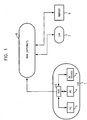
Fig. 1 shows a configuration of a telecommunications system including a LAN having personal computers and AV devices according to an embodiment of the present invention. In this telecommunication system,LANs 1 and 7, and aserver 8 are connected to one another across a WAN 6, such as the Internet. - The
LAN 1 includes personal computers (PCs) 3 and 4, and anAV device 5, all connected via a switching hub 2. TheLAN 1 is, for example, used for communication among specific individuals or a family in a house. The switching hub 2 is connected to thepersonal computers AV device 5 via a high-speed interface, such as Ethernet (R) 100BASE-TX. Data communication can take place among thepersonal computers AV device 5 at a rate of about 100 Mbps with a sufficiently low error rate. The personal computers (PCs) 3 and 4 and theAV device 5 can communicate with the LAN 7 or theserver 8 via the switching hub 2 and the WAN 6. - The personal computer (PC) 3, upon transmission of content data, can determine whether or not the other side communicating the content data is located on the
LAN 1, for example, thepersonal computer 4 or is located across the WAN 6, for example, theserver 8. - Likewise, the
personal computer 4 and theAV device 5, upon the transmission of content data, can determine whether the other side communicating the content data is located on theLAN 1, for example, thepersonal computer 3 or is located across the WAN 6, for example, theserver 8. - The LAN 7 has the same configuration as that of the
LAN 1, however, it is managed by a different user from theLAN 1. Theserver 8 is managed by a different user from theLANs 1 and 7. -
Fig. 2 shows a configuration of thepersonal computer 3. Thepersonal computer 3 incorporates a central processing unit (CPU) 21, to which an I/O interface 25 is connected via abus 24. A read only memory (ROM) 22 and a random access memory (RAM) 23 are connected to thebus 24. - The I/
O interface 25 includes aninput unit 26 composed of I/O devices, such as a keyboard and a mouse, by which a user enters operation commands, anoutput unit 27 which outputs video signals to display operation screens on a display unit, astorage unit 28 which includes a hard disk drive to store programs and other various types of data, and acommunication unit 29 which includes an Ethernet (R) interface to transmit and receive data via a 100BASE-TX cable connected to the switching hub 2. - Instead of the Ethernet (R) interface, the
communication unit 29 may include a universal serial bus (USB), or a high-speed interface, such as an Institute of Electrical and Electronics Engineers (IEEE) 1394. - Additionally, a
drive 30 which reads and writes data to and from storage media, such as amagnetic disk 31, anoptical disk 32, an opticalmagnetic disk 33, and asemiconductor memory 34, is connected to the I/O interface 25. - The
CPU 21 performs various types of processes, which will be described below, under the control of a program in theROM 22 or in theRAM 23. The program is read from themagnetic disk 31, theoptical disk 32, the opticalmagnetic disk 33, or thesemiconductor memory 34, is stored in thestorage unit 28, and is then loaded from thestorage unit 28 to theRAM 23. TheRAM 23 also stores data required for theCPU 21 to perform the various types of processes. -
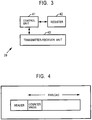
Fig. 3 shows a first configuration of a functional block achieved by thecommunication unit 29 in response to controls of theCPU 21. Acontrol unit 41 controls a transmitter-receiver unit 43 which transmits and receives data over the user datagram protocol (UDP), which is one of the communication protocols. Thecontrol unit 41 accesses aregister 42. Before the transmitter-receiver unit 43 transmits content data in response to the control of thecontrol unit 41, it transmits a predetermined number of check packets to determine whether the other side communicating the content data is located on theLAN 1 or across the WAN 6. -
Fig. 4 shows an example of the check packet. In particular, this check packet has a payload to store a counter value generated by thecontrol unit 41. - The
PC 4 and theAV device 5 have the same hardware or software functional block as that of thecommunication unit 29 shown inFig. 3 . In addition, various types of apparatuses on the LAN 7 and theserver 8 have the same functional block. - An outline of how to determine whether or not the other side communicating the content data is located on the
LAN 1 or across the WAN 6 will now be described with reference to the first configuration of thecommunication unit 29. - The UDP protocol defines that, in the case of a communication error, a packet that is not transmitted correctly is discarded and is not retransmitted. Using this characteristic, whether or not the other side communicating the content data is located on the
LAN 1 or across the WAN 6 can be determined. - More specifically, in a high-speed communication with a peer located on the
LAN 1, the switching hub 2 transmits all packets to the peer without changing the sequence of the packets, whereas in a high-speed communication with a peer across the WAN 6, a communication error occurs due to a wide area networking and the UDP protocol discards the erroneous packet. Therefore, the peer does not receive some packets or receives the packets in a different order from the transmission order. This is used to determine whether the other side communicating the content data is located on theLAN 1 or across the WAN 6. - A transmission process in the first configuration of the
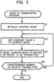
communication unit 29 shown inFig. 3 will now be described with reference to the flow chart inFig. 5 . This transmission process determines whether the other side communicating the content data is located on theLAN 1 or across the WAN 6 before the communication of content data takes place. - In step S1, the
control unit 41 assigns an initial value A to a value in a counter therein (counter value). In step S2, thecontrol unit 41 increments the counter by a constant value X, then outputs the counter value to the transmitter-receiver unit 43. In step S3, the transmitter-receiver unit 43, in response to the control of thecontrol unit 41, writes the counter value from thecontrol unit 41 into the payload of a check packet and then transmits it to the other side communicating the content data. - In step S4, the
control unit 41 determines whether the transmitter-receiver unit 43 transmits all the predetermined number of check packets. If all the predetermined number of check packets is not yet transmitted, the process returns to step S2 and the subsequent processes are repeated. If, in step S4, thecontrol unit 41 determines that all the predetermined number of check packets is transmitted, the transmission process is completed. As described above, a plurality of check packets having sequential counter values are transmitted to the receiver. - A receiving process corresponding to the above
described transmission process in the first configuration of thecommunication unit 29 will now be described with reference to a flow chart inFig. 6 . In step S11, thecontrol unit 41 stores an initial value A in theregister 42. In step S12, the transmitter-receiver unit 43 waits until the check packet transmitted from a transmitter is received. When the transmitter-receiver unit 43 receives the check packet, the process proceeds to step S13. - In step S13, the
control unit 41 computes the
difference between a counter value in a payload of the check packet received in step S12 and the value in theregister 42. In step S14, the resultant difference computed in step S13 is checked to determine if it is equal to the constant value X. If the difference is equal to the constant value X, a check packet is not lost and the packet is received in the transmission sequence, and then the process proceeds to step S15. - In step S15, the
control unit 41 stores the counter value recorded in the packet in step S13 in theregister 42. In step S16, thecontrol unit 41 determines whether the transmitter-receiver unit 43 receives all the predetermined number of check packets. If all the predetermined number of check packets is not yet received, the process returns to step S12 and the subsequent processes are repeated. Then, if, in step S16, it is determined that all the predetermined number of check packets is received, the process proceeds to step S17. - In step S17, the
control unit 41 determines LAN connection, representing that the transmitter is located on theLAN 1. - In step S14, if the difference computed in step S13 is not equal to the constant value X, a check packet is lost or the check packet is received in a different sequence from the transmission sequence. Accordingly, the process proceeds to step S18. In step S18, the
control unit 41 determines WAN connection, representing that the transmitter is located on the WAN 6. This is the end of the description of the receiving process. - For example, if it is determined that the communication takes place across a WAN connection in the receiving process, the usage of content data subsequently transmitted from the transmitter is strictly limited. In contrast, if it is determined that the communication takes place across a LAN connection, the usage of content data subsequently transmitted from the transmitter is moderately limited.
This prevents the content data from being distributed across a WAN without impairing personal use on a LAN. -
Fig. 7 shows a second configuration of a functional block achieved by thecommunication unit 29 in response to controls of theCPU 21. Acontrol unit 51 controls a transmitter-receiver unit 53, which transmits and receives data over the TCP protocol or the UDP protocol. Thecontrol unit 51 also accesses aregister 52. Before the transmitter-receiver unit 53 transmits content data in response to the control of thecontrol unit 51, it transmits a predetermined number of check packets to determine whether the other side communicating the content data is located on theLAN 1 or across the WAN 6. Atimer 54 measures time in response to the control of thecontrol unit 51. - The
PC 4 and theAV device 5 have the same hardware or software functional blocks as those of thecommunication unit 29 shown inFig. 7 . In addition, various types of apparatuses on the LAN 7 and theserver 8 have the same functional blocks. - An outline of how to determine whether or not the other side communicating the data is located on the
LAN 1 or across the WAN 6 will now be described with reference to the second configuration of thecommunication unit 29. In a communication on theLAN 1, the switching hub 2 ensures a high-speed communication rate. In contrast, in a communication across the WAN 6, the communication rate is decreased due to various reasons compared to the communication rate on theLAN 1. Based on this, it is determined whether or not the other side communicating the data is located on theLAN 1 or across the WAN 6. - A receiving process in the second configuration of the
communication unit 29 will now be described with reference to the flow chart inFig. 8 . This receiving process starts when a transmitter transmits a check packet. - In step S21, the
control unit 51 determines whether or not the transmitter-receiver unit 53 receives all the predetermined number of check packets. Thecontrol unit 51 waits until it is determined that all the predetermined number of check packets is received. If it is determined that all the predetermined number of check packets is received, the process proceeds to step S22. In step S22, thecontrol unit 51 generates acknowledgement information indicating that all the predetermined number of check packets is received, and outputs the information to the transmitter-receiver unit 53. In step S23, the transmitter-receiver unit 53 transmits the acknowledgement information to the transmitter. Preferably, the acknowledgement information cannot be forged by a third party for security reasons. For example, the transmitter and the receiver share key information as privileged information. All data or part of the data is transmitted with a hash and the key information. This is the end of the description of the receiving process. - A transmission process in the second configuration of the
communication unit 29 will now be described with reference to the flow chart inFig. 9 . In step S31, thecontrol unit 51 sets a waiting time in thetimer 54. The waiting time is determined so as to be sufficient to receive the acknowledgement information sent back from a transmitter located on theLAN 1 after transmitting a predetermined number of check packets. - In step S32, the
timer 54 starts measuring time in response to the control of thecontrol unit 51. In step S33, the transmitter-receiver unit 53 transmits a predetermined number of check packets in response to the control of thecontrol unit 51. A random number may be written into payloads of all check packets for every checking. The receiver generates the acknowledgement information with a hash and key information as described above to prevent the acknowledgement information from being forged improperly. - In step S34, the
control unit 51 determines whether or not the transmitter-receiver unit 53 receives the acknowledgement information from the receiver. If thecontrol unit 51 determines that the acknowledgement information is not received, then the process proceeds to step S35. In step S35, thecontrol unit 51 checks if the waiting time, which is set in step S31, has elapsed or not. If it is determined that it has not elapsed, the process returns to step S34 and then the subsequent steps are repeated. - If, in step S34, the
control unit 51 determines that the acknowledgement information is received, the process proceeds to step S36, where thecontrol unit 51 checks if the acknowledgement information is correct or not. If it is not correct, the process proceeds to step S38. Otherwise, the process proceeds to step S37. In step S37, thecontrol unit 51 determines that the communication takes place over a LAN connection, that is, the receiver is located on theLAN 1. In particular, to check the acknowledgement information, the transmitter may compute expected acknowledgement information as in the receiving process to compare with a value from the receiver. - If, in step S35, it is determined that the waiting time has elapsed, the process proceeds to step S38. In step S38, the
control unit 51 determines that the communication takes place across a WAN connection, that is, the receiver is located across the WAN 6. This is the end of the description of the transmission process. - For example, if it is determined that the communication takes place across a WAN connection in this transmission process, subsequent transmission of content data is stopped. In contrast, if it is determined that the communication takes place on a LAN connection, the subsequent transmission of content data is allowed. This prevents the content data from being distributed across a WAN without impairing personal use on a LAN.
- A third communication via a Transmission Control protocol (TCP) in the
communication unit 29 will now be described. In the TCP protocol, when a communication error occurs, an erroneous packet is retransmitted until all the packets are transmitted successfully. If a high-speed TCP communication that exceeds the speed of a WAN takes place, retransmissions do not occur on theLAN 1, however, retransmissions occur across the WAN 6. - A transmission process to determine whether or not the receiver is located on the
LAN 1 or across the WAN 6 by using this characteristic of the TCP protocol will now be described with reference to the flow chart inFig. 10 . This transmission process is performed before the communication of content data. In this case, the configuration of thecommunication unit 29 is identical to that inFig. 3 . - In step S41, the transmitter-
receiver unit 43 starts to transmit check packets in response to the control of thecontrol unit 41. In step S42, thecontrol unit 41 determines whether or not the transmitter-receiver unit 43 retransmits the check packets. If it is determined that retransmission of the check packets occurs, the process proceeds to step S43. - In step S43, the
control unit 41 determines WAN connection, representing that the receiver is located on the WAN 6. - If, in step S42, it is determined that retransmission of the check packets does not occur, the process proceeds to step S44. In step S44, the
control unit 41 determines whether or not the transmitter-receiver unit 43 transmits a predetermined number of check packets. If it is determined that the predetermined number of check packets is not transmitted, the process returns to step S42 and then the subsequent process is repeated. Subsequently, if, in step S44, it is determined that the predetermined number of check packets is transmitted, the process proceeds to step S45. - In step S45, the
control unit 41 determines LAN connection, representing that the receiver is located on theLAN 1. This is the end of the description of the transmission process. - For example, if it is determined that the communication takes place across a WAN connection in this transmission process, subsequent transmission of content data is stopped. In contrast, if it is determined that the communication takes place across a LAN connection, the subsequent transmission of content data is allowed. This can prevent the content data from being distributed across a WAN without impairing personal use on a LAN.
- In the present specification, the steps that describe the program stored in the storage media include not only processes executed in the above described sequence, but also processes that may be executed in parallel or independently.
- In addition, as used in the specification, "system" refers to a whole device including a plurality of devices.
- According to the present invention, it can be determined whether or not the other side communicating content data is located on a LAN or across a WAN.
Claims (11)
- A transmitting apparatus (3) comprising:a user input unit (26) configured to receive a user input;a communication interface (29) configured to transmit a check packet to a receiving apparatus using a Transmission Control Protocol (TCP); andcircuitry (21, 29) configured to:receive an acknowledgement message to the check packet transmitted using TCP from the receiving apparatus, the acknowledgement message including acknowledgement information based on shared data shared with the data receiving apparatus;compute expected acknowledgment information based on the shared data shared with the data receiving apparatus;produce a comparison result for the data receiving apparatus based on the acknowledgment information and the expected acknowledgment information;determine whether a response time of the acknowledgement message is less than a predetermined time; andprohibit transmission of content data to the data receiving apparatus when the comparison result indicates that acknowledgment information and the expected acknowledgment information do not match or when the determining determines that the response time of the acknowledgment message is larger than the predetermined time.
- The transmitting apparatus of claim 1, wherein
the shared data is a key shared between the transmitting apparatus and the receiving apparatus. - The transmitting apparatus of claim 1, wherein
the circuitry is configured to maintain a count value indicating a number of check packets that have been transmitted to the receiving apparatus, and optionally wherein:the circuitry is configured to increment the count value a constant value each time a check packet is transmitted to the receiving apparatus,or the check packet transmitted to the receiving apparatus includes data corresponding to the count value, and further optionally wherein the acknowledgment information included in the acknowledgement message is computed based on the data corresponding to the count value and the shared data,or the expected acknowledgment information is computed based on the count value and the shared data. - The transmitting apparatus of claim 1, further comprising:
a memory (23) configured to store data to be transmitted from the transmitting apparatus to the receiving apparatus, and optionally a display configured to display the data stored in the memory. - A computer program, which when executed by a transmitting apparatus, cause the transmitting apparatus to:transmit a check packet to a receiving apparatus using a Transmission Control Protocol (TCP);receive an acknowledgement message to the check packet transmitted using TCP from the receiving apparatus, the acknowledgement message including acknowledgement information based on shared data shared with the data receiving apparatus;compute expected acknowledgment information based on the shared data shared with the data receiving apparatus; produce a comparison result for the data receiving apparatus based on the acknowledgment information and the expected acknowledgment information;determine whether a response time of the acknowledgement message is less than a predetermined time; andprohibit transmission of content data to the data receiving apparatus when the comparison result indicates that acknowledgment information and the expected acknowledgment information do not match or when the determining determines that the response time of the acknowledgment message is larger than the predetermined time.
- A method performed by a transmitting apparatus, the method comprising:transmitting (S33) a check packet to a receiving apparatus using a Transmission Control Protocol (TCP);receiving (S34) an acknowledgement message to the check packet transmitted using TCP from the receiving apparatus, the acknowledgement message including acknowledgement information based on shared data shared with the receiving apparatus;computing, by circuitry of the transmitting apparatus, expected acknowledgment information based on the shared data shared with the data receiving apparatus;producing (S36), by the circuitry, a comparison result for the data receiving apparatus based on the acknowledgment information and the expected acknowledgment information;determining (S35), by the circuitry, whether a response time of the acknowledgement message is less than a predetermined time; andprohibiting (S38), by the circuitry, transmission of content data to the data receiving apparatus when the comparison result indicates that acknowledgment information and the expected acknowledgment information do not match or when the determining determines that the response time of the acknowledgment message is larger than the predetermined time,
- An information processing system having a non-transitory computer-readable medium and an interface comprising:
the non-transitory computer-readable medium including computer-program instructions, which when executed by an electronic device, cause the electronic device to:output (S33) a check packet to another information processing apparatus using Transmission Control Protocol (TCP);receive (S34) an acknowledgement message to the check packet transmitted using TCP from the another information processing apparatus, the acknowledgement message including acknowledgement information based on shared data shared with the another information processing apparatus;compute expected acknowledgment information based on the shared data shared with the another information processing apparatus;produce (S36) a comparison result for the another information processing apparatus based on the acknowledgment information and the expected acknowledgment information;determine (S35) whether a response time of the acknowledgement message is less than a predetermined time; andprohibit (S38) transmission of content data to the another information processing apparatus when the comparison result indicates that acknowledgment information and the expected acknowledgment information do not match or when the determining determines that the response time of the acknowledgment message is larger than the predetermined time. - A receiving apparatus (3) comprising:a communication interface (29) configured to receive a check packet transmitted from a transmitting apparatus according to claim 1 using a Transmission Control Protocol (TCP);circuitry (21, 29) configured to:generate an acknowledgment message to the check packet, the acknowledgment message including acknowledgment information based on shared data shared with the transmitting apparatus, wherein the shared data is a key shared between the transmitting apparatus and the receiving apparatus; andcontrol the communication interface to transmit the acknowledgment message to the transmitting apparatus using TCP; anda display configured to display data received from the data transmitting apparatus.
- The receiving apparatus of claim 8, further comprising:
a user interface configured to receive instructions input by a user. - A non-transitory computer-readable medium including computer program instructions, which when executed by a receiving apparatus, cause the receiving apparatus to:receive (S21) a check packet transmitted from a transmitting apparatus according to claim 1 using a Transmission Control Protocol (TCP);generate (S22) an acknowledgment message to the check packet, the acknowledgment message including acknowledgment information based on shared data shared with the transmitting apparatus, wherein the shared data is a key shared between the transmitting apparatus and the receiving apparatus; andtransmit (S23) the acknowledgment message to the transmitting apparatus using TCP.
- A method performed by a receiving apparatus, the method comprising:receiving (S21) a check packet transmitted from a transmitting apparatus according to claim 1 using a Transmission Control Protocol (TCP);generating (S22) an acknowledgment message to the check packet, the acknowledgment message including acknowledgment information based on shared data shared with the transmitting apparatus, wherein the shared data is a key shared between the transmitting apparatus and the receiving apparatus; andtransmitting (S23) the acknowledgment message to the data transmitting apparatus using TCP.
Applications Claiming Priority (3)
| Application Number | Priority Date | Filing Date | Title |
|---|---|---|---|
| JP2002376558A JP3801559B2 (en) | 2002-12-26 | 2002-12-26 | COMMUNICATION DEVICE AND METHOD, RECORDING MEDIUM, AND PROGRAM |
| EP03758917A EP1475925A4 (en) | 2002-12-26 | 2003-10-27 | Communication device, communication method, recording medium, and program |
| PCT/JP2003/013682 WO2004062204A1 (en) | 2002-12-26 | 2003-10-27 | Communication device, communication method, recording medium, and program |
Related Parent Applications (2)
| Application Number | Title | Priority Date | Filing Date |
|---|---|---|---|
| EP03758917.3 Division | 2003-10-27 | ||
| EP03758917A Division EP1475925A4 (en) | 2002-12-26 | 2003-10-27 | Communication device, communication method, recording medium, and program |
Publications (2)
| Publication Number | Publication Date |
|---|---|
| EP2663024A1 EP2663024A1 (en) | 2013-11-13 |
| EP2663024B1 true EP2663024B1 (en) | 2018-10-03 |
Family
ID=32708278
Family Applications (3)
| Application Number | Title | Priority Date | Filing Date |
|---|---|---|---|
| EP13179770.6A Expired - Lifetime EP2663024B1 (en) | 2002-12-26 | 2003-10-27 | Communication device, communication method, recording medium, and program |
| EP03758917A Withdrawn EP1475925A4 (en) | 2002-12-26 | 2003-10-27 | Communication device, communication method, recording medium, and program |
| EP12199835.5A Expired - Fee Related EP2575293B1 (en) | 2002-12-26 | 2003-10-27 | Telecommunications Apparatus and Method, Storage Medium, and Program |
Family Applications After (2)
| Application Number | Title | Priority Date | Filing Date |
|---|---|---|---|
| EP03758917A Withdrawn EP1475925A4 (en) | 2002-12-26 | 2003-10-27 | Communication device, communication method, recording medium, and program |
| EP12199835.5A Expired - Fee Related EP2575293B1 (en) | 2002-12-26 | 2003-10-27 | Telecommunications Apparatus and Method, Storage Medium, and Program |
Country Status (7)
| Country | Link |
|---|---|
| US (9) | US7626943B2 (en) |
| EP (3) | EP2663024B1 (en) |
| JP (1) | JP3801559B2 (en) |
| KR (1) | KR101005475B1 (en) |
| CN (4) | CN103944774B (en) |
| AU (1) | AU2003275674A1 (en) |
| WO (1) | WO2004062204A1 (en) |
Families Citing this family (18)
| Publication number | Priority date | Publication date | Assignee | Title |
|---|---|---|---|---|
| US7836597B2 (en) * | 2002-11-01 | 2010-11-23 | Cooligy Inc. | Method of fabricating high surface to volume ratio structures and their integration in microheat exchangers for liquid cooling system |
| JP3801559B2 (en) | 2002-12-26 | 2006-07-26 | ソニー株式会社 | COMMUNICATION DEVICE AND METHOD, RECORDING MEDIUM, AND PROGRAM |
| US6965564B2 (en) * | 2003-02-14 | 2005-11-15 | America Online, Inc. | Wireless datagram transaction protocol system |
| JP2005045409A (en) * | 2003-07-24 | 2005-02-17 | Pioneer Electronic Corp | Information processor, its system, its method, and its program, and recording medium with the program recorded |
| EP2317445B1 (en) * | 2003-07-28 | 2018-11-07 | Sony Corporation | Information processing apparatus and method, recording medium and program |
| JP4270033B2 (en) * | 2004-06-11 | 2009-05-27 | ソニー株式会社 | Communication system and communication method |
| JP4834737B2 (en) * | 2005-10-14 | 2011-12-14 | コーニンクレッカ フィリップス エレクトロニクス エヌ ヴィ | Improved proximity detection method |
| JP2007180611A (en) * | 2005-12-26 | 2007-07-12 | Toshiba Corp | Communication system and communication method |
| US7739502B2 (en) * | 2006-01-10 | 2010-06-15 | Samsung Electronics Co., Ltd. | Localization determination process for 1394 serial bus |
| US20070162740A1 (en) * | 2006-01-12 | 2007-07-12 | Relan Sandeep K | Systems, methods, and apparatus for packet level security |
| US20090055751A1 (en) * | 2007-08-24 | 2009-02-26 | Microsoft Corporation | Management System for Local and Remote Services |
| US9013074B2 (en) | 2010-05-25 | 2015-04-21 | Regal Beloit America, Inc. | Resilient rotor assembly for interior permanent magnet motor |
| US9203717B2 (en) * | 2013-12-19 | 2015-12-01 | Google Inc. | Detecting network devices |
| US10592108B2 (en) * | 2014-09-30 | 2020-03-17 | Anthony Tan | Secured storage system with temporary external assignable memory |
| US11101978B2 (en) * | 2015-02-18 | 2021-08-24 | Telefonaktiebolaget Lm Ericsson (Publ) | Establishing and managing identities for constrained devices |
| CN108028779B (en) * | 2015-07-28 | 2021-06-29 | 马维尔国际贸易有限公司 | Deliberately corrupted packets for connection information |
| CN108365924B (en) * | 2017-01-26 | 2021-02-12 | 华为技术有限公司 | Data retransmission method and communication device |
| US20230046788A1 (en) * | 2021-08-16 | 2023-02-16 | Capital One Services, Llc | Systems and methods for resetting an authentication counter |
Citations (2)
| Publication number | Priority date | Publication date | Assignee | Title |
|---|---|---|---|---|
| US5550807A (en) * | 1994-03-04 | 1996-08-27 | Fujitsu Limited | Method of measuring distance between equipments on lan and distance measuring apparatus |
| WO2004030311A1 (en) * | 2002-09-30 | 2004-04-08 | Koninklijke Philips Electronics N.V. | Secure proximity verification of a node on a network |
Family Cites Families (40)
| Publication number | Priority date | Publication date | Assignee | Title |
|---|---|---|---|---|
| WO1990007329A1 (en) * | 1989-01-06 | 1990-07-12 | The Regents Of The University Of California | Selection method for pharmacologically active compounds |
| JPH06508008A (en) * | 1991-06-12 | 1994-09-08 | ヒューレット・パッカード・カンパニー | Method and apparatus for testing packet-based networks |
| JP3070868B2 (en) * | 1991-06-26 | 2000-07-31 | 日本電気通信システム株式会社 | ATM cell sequence evaluation circuit |
| GB2281991A (en) * | 1993-09-10 | 1995-03-22 | Icl Systems Ab | Authentication |
| CA2179223C (en) * | 1995-06-23 | 2009-01-06 | Manfred Von Willich | Method and apparatus for controlling the operation of a signal decoder in a broadcasting system |
| US5970143A (en) * | 1995-11-22 | 1999-10-19 | Walker Asset Management Lp | Remote-auditing of computer generated outcomes, authenticated billing and access control, and software metering system using cryptographic and other protocols |
| US5699361A (en) * | 1995-07-18 | 1997-12-16 | Industrial Technology Research Institute | Multimedia channel formulation mechanism |
| KR100473536B1 (en) * | 1996-05-22 | 2005-05-16 | 마츠시타 덴끼 산교 가부시키가이샤 | An encryption apparatus for ensuring security in communication between devices and communication system |
| KR100363607B1 (en) * | 1996-06-05 | 2003-01-24 | 지멘스 악티엔게젤샤프트 | Process for cryptographic code management between a first computer unit and a second computer unit |
| JP3201265B2 (en) | 1996-06-12 | 2001-08-20 | 富士ゼロックス株式会社 | Data transmission apparatus and method |
| US5729537A (en) * | 1996-06-14 | 1998-03-17 | Telefonaktiebolaget L M Ericsson (Publ) | Method and apparatus for providing anonymous data transfer in a communication system |
| EP0951767A2 (en) * | 1997-01-03 | 1999-10-27 | Fortress Technologies, Inc. | Improved network security device |
| US6032197A (en) * | 1997-09-25 | 2000-02-29 | Microsoft Corporation | Data packet header compression for unidirectional transmission |
| US6151676A (en) * | 1997-12-24 | 2000-11-21 | Philips Electronics North America Corporation | Administration and utilization of secret fresh random numbers in a networked environment |
| JP4062757B2 (en) | 1998-01-16 | 2008-03-19 | 富士ゼロックス株式会社 | Licensing system and licensing method |
| US6012096A (en) * | 1998-04-23 | 2000-01-04 | Microsoft Corporation | Method and system for peer-to-peer network latency measurement |
| JP2000003336A (en) * | 1998-06-16 | 2000-01-07 | Nec Corp | Method and system for user authentication in portable type data communication terminal |
| US7165152B2 (en) * | 1998-06-30 | 2007-01-16 | Emc Corporation | Method and apparatus for managing access to storage devices in a storage system with access control |
| US6389016B1 (en) * | 1998-10-14 | 2002-05-14 | Nortel Networks Limited | Data communication system and method for transporting data |
| US6360269B1 (en) * | 1998-11-02 | 2002-03-19 | Nortel Networks Limited | Protected keepalive message through the internet |
| US6721555B1 (en) * | 1999-02-19 | 2004-04-13 | Qualcomm Incorporated | System and method for facilitating device authentication in a wireless communications system |
| EP1045551A3 (en) * | 1999-04-15 | 2003-06-18 | Lucent Technologies Inc. | Method for transmission between data networks and wireless communication system |
| FR2793628A1 (en) * | 1999-05-11 | 2000-11-17 | Koninkl Philips Electronics Nv | TRANSMISSION SYSTEM, RECEIVER AND INTERCONNECTION NETWORK |
| KR100580159B1 (en) * | 1999-06-28 | 2006-05-15 | 삼성전자주식회사 | Digital interface method for preventing an illegal copy |
| JP2001053794A (en) * | 1999-08-09 | 2001-02-23 | Nec Corp | Real time backup communication method for ip communication |
| JP3749817B2 (en) | 2000-03-30 | 2006-03-01 | 株式会社東芝 | Transmitting apparatus and transmitting method thereof |
| US6738379B1 (en) * | 2000-03-30 | 2004-05-18 | Telefonaktiebolaget Lm Ericsson (Publ) | Method of preserving data packet sequencing |
| IT1318466B1 (en) | 2000-04-14 | 2003-08-25 | Dompe Spa | R-2- (AMINOARYL) -PROPIONIC ACIDS AMIDES, USEFUL IN THE PREVENTION OF LEUKOCYTIVE ACTIVATION. |
| JP3642258B2 (en) | 2000-05-08 | 2005-04-27 | 松下電器産業株式会社 | Video composition device |
| WO2002003179A2 (en) * | 2000-06-30 | 2002-01-10 | Williams Eddie H | Online digital content library |
| JP2002033733A (en) * | 2000-07-17 | 2002-01-31 | Sharp Corp | Host computer and network system |
| US7937470B2 (en) * | 2000-12-21 | 2011-05-03 | Oracle International Corp. | Methods of determining communications protocol latency |
| US20030105831A1 (en) * | 2001-12-04 | 2003-06-05 | O'kane Robert | Peer-to-peer (P2P) and internet content delivery based user based digital acknowledgement trigger used for file transfer |
| CN1672382B (en) | 2002-07-26 | 2010-09-01 | 皇家飞利浦电子股份有限公司 | Secure authenticated distance measurement |
| US7398392B2 (en) * | 2002-11-15 | 2008-07-08 | Cable Television Laboratories, Inc. | Method for using communication channel round-trip response time for digital asset management |
| JP3801559B2 (en) | 2002-12-26 | 2006-07-26 | ソニー株式会社 | COMMUNICATION DEVICE AND METHOD, RECORDING MEDIUM, AND PROGRAM |
| JP4881538B2 (en) * | 2003-06-10 | 2012-02-22 | 株式会社日立製作所 | Content transmitting apparatus and content transmitting method |
| EP2317445B1 (en) * | 2003-07-28 | 2018-11-07 | Sony Corporation | Information processing apparatus and method, recording medium and program |
| US9342662B2 (en) * | 2003-09-16 | 2016-05-17 | Media Rights Technologies, Inc. | Method and system for controlling video media |
| JP4270033B2 (en) | 2004-06-11 | 2009-05-27 | ソニー株式会社 | Communication system and communication method |
-
2002
- 2002-12-26 JP JP2002376558A patent/JP3801559B2/en not_active Expired - Lifetime
-
2003
- 2003-10-27 CN CN201310729369.1A patent/CN103944774B/en not_active Expired - Lifetime
- 2003-10-27 CN CN2003801002790A patent/CN1692610B/en not_active Expired - Fee Related
- 2003-10-27 CN CN201110243178.5A patent/CN102377615B/en not_active Expired - Fee Related
- 2003-10-27 CN CN201310728343.5A patent/CN103944773B/en not_active Expired - Lifetime
- 2003-10-27 EP EP13179770.6A patent/EP2663024B1/en not_active Expired - Lifetime
- 2003-10-27 US US10/503,931 patent/US7626943B2/en active Active
- 2003-10-27 KR KR20047013370A patent/KR101005475B1/en active IP Right Grant
- 2003-10-27 AU AU2003275674A patent/AU2003275674A1/en not_active Abandoned
- 2003-10-27 WO PCT/JP2003/013682 patent/WO2004062204A1/en active Application Filing
- 2003-10-27 EP EP03758917A patent/EP1475925A4/en not_active Withdrawn
- 2003-10-27 EP EP12199835.5A patent/EP2575293B1/en not_active Expired - Fee Related
-
2006
- 2006-03-10 US US11/372,119 patent/US7656875B2/en not_active Expired - Fee Related
-
2009
- 2009-07-31 US US12/533,746 patent/US8289880B2/en not_active Expired - Lifetime
- 2009-12-03 US US12/630,595 patent/US8264984B2/en not_active Expired - Lifetime
-
2012
- 2012-07-03 US US13/541,179 patent/US8611342B2/en not_active Expired - Lifetime
- 2012-09-06 US US13/605,437 patent/US8611253B2/en not_active Expired - Lifetime
-
2013
- 2013-08-02 US US13/958,381 patent/US8930695B2/en not_active Expired - Lifetime
- 2013-08-02 US US13/958,384 patent/US8743739B2/en not_active Expired - Fee Related
-
2014
- 2014-11-24 US US14/552,023 patent/US9594882B2/en not_active Expired - Lifetime
Patent Citations (2)
| Publication number | Priority date | Publication date | Assignee | Title |
|---|---|---|---|---|
| US5550807A (en) * | 1994-03-04 | 1996-08-27 | Fujitsu Limited | Method of measuring distance between equipments on lan and distance measuring apparatus |
| WO2004030311A1 (en) * | 2002-09-30 | 2004-04-08 | Koninklijke Philips Electronics N.V. | Secure proximity verification of a node on a network |
Also Published As
Similar Documents
| Publication | Publication Date | Title |
|---|---|---|
| US9594882B2 (en) | Telecommunications apparatus and method, storage medium, and program | |
| US9584480B2 (en) | System for and method of securing a network utilizing credentials | |
| US6662223B1 (en) | Protocol to coordinate network end points to measure network latency | |
| US20130318350A1 (en) | Information processing apparatus and method, recording medium and program | |
| Mathis et al. | TCP extended statistics MIB | |
| CN109547172A (en) | Data transmission method, system and data transmitting equipment, data receiver | |
| JP4069458B2 (en) | Data communication system and data communication method, data transmission device and data transmission method, data reception device and data reception method, and program | |
| JP4592705B2 (en) | Method for monitoring a message for initiating a multimedia stream exchange session and server and equipment for performing said method | |
| US20070086352A1 (en) | Method of monitoring multimedia stream exchange session initialization messages and a server and an installation for carrying out said method | |
| MIB | Network Working Group M. Mathis Request for Comments: 4898 J. Heffner Category: Standards Track Pittsburgh Supercomputing Center R. Raghunarayan Cisco Systems |
Legal Events
| Date | Code | Title | Description |
|---|---|---|---|
| PUAI | Public reference made under article 153(3) epc to a published international application that has entered the european phase |
Free format text: ORIGINAL CODE: 0009012 |
|
| 17P | Request for examination filed |
Effective date: 20130808 |
|
| AC | Divisional application: reference to earlier application |
Ref document number: 1475925 Country of ref document: EP Kind code of ref document: P |
|
| AK | Designated contracting states |
Kind code of ref document: A1 Designated state(s): DE FR GB |
|
| 17Q | First examination report despatched |
Effective date: 20160308 |
|
| STAA | Information on the status of an ep patent application or granted ep patent |
Free format text: STATUS: EXAMINATION IS IN PROGRESS |
|
| GRAP | Despatch of communication of intention to grant a patent |
Free format text: ORIGINAL CODE: EPIDOSNIGR1 |
|
| STAA | Information on the status of an ep patent application or granted ep patent |
Free format text: STATUS: GRANT OF PATENT IS INTENDED |
|
| INTG | Intention to grant announced |
Effective date: 20180424 |
|
| GRAS | Grant fee paid |
Free format text: ORIGINAL CODE: EPIDOSNIGR3 |
|
| GRAA | (expected) grant |
Free format text: ORIGINAL CODE: 0009210 |
|
| STAA | Information on the status of an ep patent application or granted ep patent |
Free format text: STATUS: THE PATENT HAS BEEN GRANTED |
|
| AC | Divisional application: reference to earlier application |
Ref document number: 1475925 Country of ref document: EP Kind code of ref document: P |
|
| AK | Designated contracting states |
Kind code of ref document: B1 Designated state(s): DE FR GB |
|
| REG | Reference to a national code |
Ref country code: GB Ref legal event code: FG4D |
|
| REG | Reference to a national code |
Ref country code: FR Ref legal event code: PLFP Year of fee payment: 16 |
|
| REG | Reference to a national code |
Ref country code: DE Ref legal event code: R096 Ref document number: 60351542 Country of ref document: DE |
|
| REG | Reference to a national code |
Ref country code: DE Ref legal event code: R097 Ref document number: 60351542 Country of ref document: DE |
|
| PLBE | No opposition filed within time limit |
Free format text: ORIGINAL CODE: 0009261 |
|
| STAA | Information on the status of an ep patent application or granted ep patent |
Free format text: STATUS: NO OPPOSITION FILED WITHIN TIME LIMIT |
|
| 26N | No opposition filed |
Effective date: 20190704 |
|
| PGFP | Annual fee paid to national office [announced via postgrant information from national office to epo] |
Ref country code: FR Payment date: 20191028 Year of fee payment: 17 |
|
| PGFP | Annual fee paid to national office [announced via postgrant information from national office to epo] |
Ref country code: GB Payment date: 20191021 Year of fee payment: 17 |
|
| GBPC | Gb: european patent ceased through non-payment of renewal fee |
Effective date: 20201027 |
|
| PG25 | Lapsed in a contracting state [announced via postgrant information from national office to epo] |
Ref country code: FR Free format text: LAPSE BECAUSE OF NON-PAYMENT OF DUE FEES Effective date: 20201031 |
|
| PG25 | Lapsed in a contracting state [announced via postgrant information from national office to epo] |
Ref country code: GB Free format text: LAPSE BECAUSE OF NON-PAYMENT OF DUE FEES Effective date: 20201027 |
|
| REG | Reference to a national code |
Ref country code: DE Ref legal event code: R079 Ref document number: 60351542 Country of ref document: DE Free format text: PREVIOUS MAIN CLASS: H04L0012260000 Ipc: H04L0043000000 |
|
| PGFP | Annual fee paid to national office [announced via postgrant information from national office to epo] |
Ref country code: DE Payment date: 20220616 Year of fee payment: 20 |
|
| P01 | Opt-out of the competence of the unified patent court (upc) registered |
Effective date: 20230527 |
|
| REG | Reference to a national code |
Ref country code: DE Ref legal event code: R071 Ref document number: 60351542 Country of ref document: DE |