EP2662951A2 - Stator lamination stack alignment and retention - Google Patents
Stator lamination stack alignment and retention Download PDFInfo
- Publication number
- EP2662951A2 EP2662951A2 EP13163451.1A EP13163451A EP2662951A2 EP 2662951 A2 EP2662951 A2 EP 2662951A2 EP 13163451 A EP13163451 A EP 13163451A EP 2662951 A2 EP2662951 A2 EP 2662951A2
- Authority
- EP
- European Patent Office
- Prior art keywords
- slot
- electrical device
- stator
- laminations
- housing
- Prior art date
- Legal status (The legal status is an assumption and is not a legal conclusion. Google has not performed a legal analysis and makes no representation as to the accuracy of the status listed.)
- Granted
Links
Images
Classifications
-
- H—ELECTRICITY
- H02—GENERATION; CONVERSION OR DISTRIBUTION OF ELECTRIC POWER
- H02K—DYNAMO-ELECTRIC MACHINES
- H02K1/00—Details of the magnetic circuit
- H02K1/06—Details of the magnetic circuit characterised by the shape, form or construction
- H02K1/12—Stationary parts of the magnetic circuit
- H02K1/18—Means for mounting or fastening magnetic stationary parts on to, or to, the stator structures
- H02K1/185—Means for mounting or fastening magnetic stationary parts on to, or to, the stator structures to outer stators
Definitions
- the present invention relates to an electrical device such as a motor or generator, and, more particularly, to an apparatus and method of indexing and retaining stator laminations in the housing of an electrical device.
- Electrical devices such as generators and motors include a stator and a rotor.
- a stator is stationary and a rotor rotates in an electrical device, although the opposite can also be the case.
- the stator may act as a field magnet interacting with the rotor to create motion in the rotor.
- the stator may receive magnetic fields from the moving field coils of the rotor to thereby produce electrical power from the stator.
- a stator may be a permanent magnet
- electromagnets are typically used having what is caused a field coil or field winding that is closely associated with a series of laminations to produce the electromagnet.
- the laminations are typically of a ferrous material such as silicone steel with the geometry and material type selected to reduce hysteresis and eddy current losses.
- the laminations are typically identically stamped and are stacked in their arrangement with copper winding wire interfacing elements of the laminations to form the electromagnetic field coils of the stator assembly.
- the stator is then dipped or coated in a varnish-like material to adhere the parts together and to reduce or prevent vibration between the laminations.
- the stator assembly is then inserted into a housing and secured thereto.
- the rotor then is inserted inside a central cavity of the stator along with bearings. If the rotor uses electromagnets, then slip rings are also coupled with the rotor to supply electrical conduction pathways to the coils contained in the rotor.
- the present invention provides for the clocking of a stator relative to a housing to thereby orient the stator rotationally and axially relative to the housing and retaining it thereto.
- the invention in one form is directed to an electrical device including a housing having an inner surface, a lamination assembly and at least one pin extending from an inner surface of the housing.
- the lamination assembly has at least one slot therein.
- the lamination assembly is clocked to a position so that the at least one pin coacts with the at least one slot to rotationally orient the lamination assembly.
- the at least one pin additionally acts to constrain the lamination assembly from axial removal from the housing thereby rotationally and axially limiting movement of the lamination assembly to a predetermined range of movement within the housing.
- the invention in another form is directed to an electrical device having a housing, a stator and at least one pin extending from the inner surface of the housing.
- the stator has at least one slot along an outer surface of the stator.
- the stator is clocked to a position so that the at least one pin coacts with the at last one slot to rotationally orient the stator as the stator is inserted into the housing.
- the at least one pin additionally acts to constrain the stator from axial movement to thereby rotationally and axially position the stator in a predetermined position in the housing.
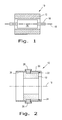
- an electrical device 10 which can also be an electrical motor or an electrical generator, having a stator 12, a rotor 14, and a shaft 16 that is oriented to rotate about axis 18.
- Stator 12 can also be understood to be a lamination assembly 12 as further described herein.
- elements such as slip rings, electrical connections, bearings, windings and the housing of the motor are not illustrated in Fig. 1 .
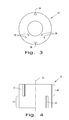
- FIG. 2 there is illustrated electrical device 10, with stator 12 inserted inside of a housing 20.
- Stator 12 has slots 22 and 24 that are shown interacting with pins 26 and 28.
- Pins 26 and 28 extend from an inner surface 30 of housing 20 and are shown engaging slots 22 and 24 respectively.
- pins 26 and 28 are inserted to allow lamination assembly 12 to be oriented or clocked into position so that slot 22 corresponds with pin 26 and slot 24 corresponds with pin 28.
- two slots 22 and 24 as well as two pins 26 and 28 are illustrated, other corresponding numbers of each or different numbers of each are also contemplated. Further, for the ease of illustration slots 22 and 24 are shown opposite each other, but other locations are also contemplated.
- pins 26 and 28 prevent further axial movement of lamination assembly 12 once they encounter pins 26 and 28.
- pins 26 and 28 do not extend inwardly to contact the bottom surfaces of slots 22 and 24 thereby allowing lamination assembly 12 to be retained in housing 20, so that lamination assembly 12 can be positioned and fastened in a conventional manner later in the assembly process.
- Pins 26 and 28 may be in the form of fasteners or other devices that are inserted through housing 20 to thereby engage slots 22 and 24 with the purpose of rotational alignment or the clocking of lamination assembly 12 and in order to restrain the axial movement beyond the desired position and to prevent the removal of lamination assembly 12 from housing 20.
- Pins 26 and 28 constrain the movement of lamination assembly 12 within housing 20 within a predetermined range of movement as determined by the size of pins 26 and 28 as well as the geometry of slots 22 and 24. Pins 26 and 28 may just hold lamination assembly 12 temporarily until other elements, not shown, are then further secured to housing 20.
- Slots 22 and 24 may be machined into lamination assembly 12 after the laminations are stacked or otherwise positioned and slots 22 and 24 do not necessarily have a dead end or closed end as illustrated in Fig. 2 but may extend from one end of lamination assembly 12 to the other end of lamination assembly 12. Also, slots 22 and 24 may be closed on both ends. Further, although slots 22 and 24 are illustrated as being parallel with axis 18 other configurations and shapes are also contemplated such as a round bore of fixed depth.
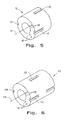
- a singular lamination 32 having notches 34 and 36, and orientation features 38 and 40.
- Laminations 32 are chosen to have a desired thickness for the purposes of reducing hysteresis and eddy current losses in the assembly.
- Laminations 32 may be made in a stamping process having notches 34 and 36 that then will be subsequently aligned so as to form slots 22 and 24 respectively.
- Orientation features 38 and 40 are shown as examples of features which exist around the surface of lamination 32.
- Orientation features 38 and 40 include wiring paths that are oriented so that multiple aligning positions of features 38 and 40 may occur around the surface of lamination 32 such that features 38 and 40 may align while notches 34 and 36 may misalign so that features 38 and 40 can be utilized, for example, for the routing of copper wiring while certain portions of notches 34 and 36 may or may not be aligned.
- This feature is illustrated in Fig. 4 , as a stack of laminations 32 that have a first portion 44 of the stack of laminations and a second portion 46 of the stack of laminations. Portion 44 and portion 46 are offset, say for example by ninety degrees, to thereby form slot 42 in a different angular and axial position from slot 22.
- orientation features 38 and 40 align throughout the length of lamination assembly 12 while slots 22, 42 and 48 are formed by the positioning of notches 34 and 36.
- the hidden lines illustrate that orientation features 38 and 40 are aligned and extend through the entire lamination assembly 12.
- slot 122 can be formed having two dead ends with portions of laminations 32 oriented in one direction and in a second direction and then back to a first direction so that slot 142 is interrupted by the offset and allowing the formation of slot 122.
- the elements of Fig. 6 are conveniently numbered one hundred higher than similar features illustrated in Figs. 1-5 and have the same characteristics as those discussed by their lower number counterparts.
- Pin 26 and/or pin 28 are used to precisely control the clocking of lamination assembly 12 so that the size of pins 26 and 28 may correspond to the width of slots 22 and 24.
- the looser control of the axial position is available during the assembly and disassembly processes to hold stator 12 proximate to its proper place to prevent stator 12 from backing out of housing 20 during the handling and assembly/disassembly of electrical device 10.
- stator lamination stack 12 is inserted into housing 20 also known as a frame. Fixturing can be used to ensure that slots 22 and 24 will line up respectively with radial pins 26 and 28 during the insertion process.
- radial pins 26 and 28 can be inserted or inserted further. Pins 26 and 28 engage axial slots 22 and 24 respectively which are formed as notches in lamination 32 or machined to a predetermined depth in the outer surface of the lamination stack. Slots 22 and 24 as illustrated herein only covering a portion of the total lamination stack of lamination assembly 12.
- Radial pins 26 and 28 may contain a feature to lock them in to place to prevent them from disengaging from slots 22 and 24. Once pins 26 and 28 are inserted, lamination assembly 12 is prevented from turning about axis 18 within housing 20 and also from excess axial movement within electrical device 10.
- the present invention adds the combination of a slot on the stator and extending pins so that the stator can be properly oriented within housing 20 during assembly of electrical device 10.
Landscapes
- Engineering & Computer Science (AREA)
- Power Engineering (AREA)
- Iron Core Of Rotating Electric Machines (AREA)
- Connection Of Plates (AREA)
- Manufacture Of Motors, Generators (AREA)
- Motor Or Generator Frames (AREA)
Abstract
Description
- The present invention relates to an electrical device such as a motor or generator, and, more particularly, to an apparatus and method of indexing and retaining stator laminations in the housing of an electrical device.
- Electrical devices such as generators and motors include a stator and a rotor. Typically a stator is stationary and a rotor rotates in an electrical device, although the opposite can also be the case. The stator may act as a field magnet interacting with the rotor to create motion in the rotor. Alternatively the stator may receive magnetic fields from the moving field coils of the rotor to thereby produce electrical power from the stator. Although a stator may be a permanent magnet, electromagnets are typically used having what is caused a field coil or field winding that is closely associated with a series of laminations to produce the electromagnet. The laminations are typically of a ferrous material such as silicone steel with the geometry and material type selected to reduce hysteresis and eddy current losses.
- The laminations are typically identically stamped and are stacked in their arrangement with copper winding wire interfacing elements of the laminations to form the electromagnetic field coils of the stator assembly. Typically the stator is then dipped or coated in a varnish-like material to adhere the parts together and to reduce or prevent vibration between the laminations. The stator assembly is then inserted into a housing and secured thereto. The rotor then is inserted inside a central cavity of the stator along with bearings. If the rotor uses electromagnets, then slip rings are also coupled with the rotor to supply electrical conduction pathways to the coils contained in the rotor.
- What is needed in the art is a cost effective way of aligning the stator to the housing as well as retaining it in at least a temporary fashion until being fully secured to the housing.
- The present invention provides for the clocking of a stator relative to a housing to thereby orient the stator rotationally and axially relative to the housing and retaining it thereto.
- The invention in one form is directed to an electrical device including a housing having an inner surface, a lamination assembly and at least one pin extending from an inner surface of the housing. The lamination assembly has at least one slot therein. The lamination assembly is clocked to a position so that the at least one pin coacts with the at least one slot to rotationally orient the lamination assembly. The at least one pin additionally acts to constrain the lamination assembly from axial removal from the housing thereby rotationally and axially limiting movement of the lamination assembly to a predetermined range of movement within the housing.
- The invention in another form is directed to an electrical device having a housing, a stator and at least one pin extending from the inner surface of the housing. The stator has at least one slot along an outer surface of the stator. The stator is clocked to a position so that the at least one pin coacts with the at last one slot to rotationally orient the stator as the stator is inserted into the housing. The at least one pin additionally acts to constrain the stator from axial movement to thereby rotationally and axially position the stator in a predetermined position in the housing.
- The above-mentioned and other features and advantages of this invention, and the manner of attaining them, will become more apparent and the invention will be better understood by reference to the following description of embodiments of the invention taken in conjunction with the accompanying drawings, wherein:
-
Fig. 1 is an abstract cross-sectional view of an electrical device made utilizing an embodiment of the present invention; -
Fig. 2 is a cross-section view of the stator laminations used in the electrical device of theFig. 1 ; -
Fig. 3 is a plan view of a lamination utilized in the stator assembly ofFigs. 1 and 2 ; -
Fig. 4 is a side view of a stack of the laminations ofFig. 3 to thereby form the lamination assembly of the stator ofFigs. 1 and 2 ; -
Fig. 5 is a perspective view of the lamination stack ofFig. 4 ; and -
Fig. 6 is another perspective view of another embodiment of a stack of laminations ofFig. 3 . - Corresponding reference characters indicate corresponding parts throughout the several views. Referring now to the drawings, and more particularly to
Fig. 1 , there is shown anelectrical device 10, which can also be an electrical motor or an electrical generator, having astator 12, arotor 14, and ashaft 16 that is oriented to rotate aboutaxis 18.Stator 12 can also be understood to be alamination assembly 12 as further described herein. For the sake of simplicity elements such as slip rings, electrical connections, bearings, windings and the housing of the motor are not illustrated inFig. 1 . - Now, additionally referring to
Fig. 2 there is illustratedelectrical device 10, withstator 12 inserted inside of ahousing 20. Stator 12 hasslots pins Pins inner surface 30 ofhousing 20 and are shownengaging slots lamination assembly 12 is inserted into the end ofhousing 20,pins lamination assembly 12 to be oriented or clocked into position so thatslot 22 corresponds withpin 26 andslot 24 corresponds withpin 28. Although twoslots pins illustration slots lamination assembly 12 is inserted, the end ofslots lamination assembly 12 once they encounterpins Fig. 2 pins slots lamination assembly 12 to be retained inhousing 20, so thatlamination assembly 12 can be positioned and fastened in a conventional manner later in the assembly process.Pins housing 20 to thereby engageslots lamination assembly 12 and in order to restrain the axial movement beyond the desired position and to prevent the removal oflamination assembly 12 fromhousing 20.Pins lamination assembly 12 withinhousing 20 within a predetermined range of movement as determined by the size ofpins slots Pins lamination assembly 12 temporarily until other elements, not shown, are then further secured to housing 20. -
Slots lamination assembly 12 after the laminations are stacked or otherwise positioned andslots Fig. 2 but may extend from one end oflamination assembly 12 to the other end oflamination assembly 12. Also,slots slots axis 18 other configurations and shapes are also contemplated such as a round bore of fixed depth. - Now, additionally referring to
Figs. 3-5 , there is illustrated inFig. 3 asingular lamination 32 havingnotches Laminations 32 are chosen to have a desired thickness for the purposes of reducing hysteresis and eddy current losses in the assembly.Laminations 32 may be made in a stampingprocess having notches slots Orientation features lamination 32. Orientation features 38 and 40 include wiring paths that are oriented so that multiple aligning positions offeatures lamination 32 such that features 38 and 40 may align whilenotches features notches Fig. 4 , as a stack oflaminations 32 that have afirst portion 44 of the stack of laminations and asecond portion 46 of the stack of laminations.Portion 44 andportion 46 are offset, say for example by ninety degrees, to thereby formslot 42 in a different angular and axial position fromslot 22. This is accomplished by a rotation ofportion 46, for example, of ninety degrees fromportion 44 so thatnotches portions Fig. 5 orientation features 38 and 40 align throughout the length oflamination assembly 12 whileslots notches entire lamination assembly 12. - In another embodiment of the present invention illustrated in
Fig. 6 ,slot 122 can be formed having two dead ends with portions oflaminations 32 oriented in one direction and in a second direction and then back to a first direction so thatslot 142 is interrupted by the offset and allowing the formation ofslot 122. The elements ofFig. 6 are conveniently numbered one hundred higher than similar features illustrated inFigs. 1-5 and have the same characteristics as those discussed by their lower number counterparts. -
Pin 26 and/orpin 28 are used to precisely control the clocking oflamination assembly 12 so that the size ofpins slots stator 12 proximate to its proper place to preventstator 12 from backing out ofhousing 20 during the handling and assembly/disassembly ofelectrical device 10. - As shown in
Fig. 2 ,stator lamination stack 12 is inserted intohousing 20 also known as a frame. Fixturing can be used to ensure thatslots radial pins lamination assembly 12 are inserted to the predetermined depth or location,radial pins Pins axial slots lamination 32 or machined to a predetermined depth in the outer surface of the lamination stack.Slots lamination assembly 12. Radial pins 26 and 28 may contain a feature to lock them in to place to prevent them from disengaging fromslots lamination assembly 12 is prevented from turning aboutaxis 18 withinhousing 20 and also from excess axial movement withinelectrical device 10. - Advantageously the present invention adds the combination of a slot on the stator and extending pins so that the stator can be properly oriented within
housing 20 during assembly ofelectrical device 10.
Claims (15)
- An electrical device, comprising:a housing having an inner surface;a lamination assembly having at least one slot therein; andat least one pin extending from said inner surface of said housing, said lamination assembly being clocked to a position so that said at least one pin coacts with said at least one slot to rotationally orient said lamination assembly, said at least one pin additionally constraining said lamination assembly from axial removal from said housing to thereby rotationally and axially constrain said lamination assembly to a limited range of movement in said housing.
- The electrical device of claim 1, wherein said at least one slot is substantially linear in an axial direction along an outer surface of said lamination assembly.
- The electrical device of claim 2, wherein said at least one slot does not extend along an entire axial length of said lamination assembly.
- The electrical device of claim 3, wherein said lamination assembly includes a plurality of laminations positioned into a stack, at least some of said plurality of laminations being substantially identical to each other.
- The electrical device of claim 4, wherein said at least one slot is formed in said lamination assembly after said plurality of laminations are positioned into said stack.
- The electrical device of claim 4, wherein at least some of said plurality of laminations have at least one notch, said at least one notch of each of said at least some of said plurality of laminations being aligned in said stack to form said at least one slot.
- The electrical device of claim 6, wherein substantially all of said plurality of laminations have said at least one notch, said at least one slot being formed by a first portion of said plurality of laminations being aligned so said at least one notch of each said first portion of said plurality of laminations form said at least one slot, a second portion of said plurality of laminations being rotationally oriented so that said at least one notch does not align with said at least one slot thereby causing an end to said at least one slot.
- The electrical device of claim 7, wherein said plurality of laminations additionally have a plurality of orientation features other than said at least one notch, said orientation features of said first portion being aligned with said orientation features of said second portion.
- The electrical device of claim 1, wherein said lamination assembly is constrained in said axial direction relative to said housing by way of said at least one pin encountering an end to said slot in said axial direction.
- The electrical device of claim 1, wherein the electrical device is one of an electric generator and an electric motor, said lamination assembly being a stator.
- An electrical device, comprising:a housing having an inner surface;a stator having at least one slot along an outer surface of said stator; andat least one pin extending from said inner surface of said housing, said stator being clocked to a position so that said at least one pin coacts with said at least one slot to rotationally orient said stator, said at least one pin additionally acting to constrain said stator from axial removal from said housing thereby rotationally and axially limiting movement of said stator to a predetermined range of movement within said housing..
- The electrical device of claim 11, wherein said at least one slot is substantially linear in an axial direction along an outer surface of said stator.
- The electrical device of claim 12, wherein said at least one slot does not extend along an entire axial length of said stator.
- The electrical device of claim 13, wherein said stator includes a plurality of laminations positioned into a stack, at least some of said plurality of laminations being substantially identical to each other.
- The electrical device of claim 14, wherein said at least one slot is formed in said stator after said plurality of laminations are positioned into said stack.
Applications Claiming Priority (1)
| Application Number | Priority Date | Filing Date | Title |
|---|---|---|---|
| US13/466,273 US9438076B2 (en) | 2012-05-08 | 2012-05-08 | Stator lamination stack indexing and retention |
Publications (3)
| Publication Number | Publication Date |
|---|---|
| EP2662951A2 true EP2662951A2 (en) | 2013-11-13 |
| EP2662951A3 EP2662951A3 (en) | 2017-09-13 |
| EP2662951B1 EP2662951B1 (en) | 2020-11-18 |
Family
ID=48143085
Family Applications (1)
| Application Number | Title | Priority Date | Filing Date |
|---|---|---|---|
| EP13163451.1A Active EP2662951B1 (en) | 2012-05-08 | 2013-04-12 | Stator lamination stack alignment and retention |
Country Status (5)
| Country | Link |
|---|---|
| US (1) | US9438076B2 (en) |
| EP (1) | EP2662951B1 (en) |
| CN (1) | CN103390940B (en) |
| BR (1) | BR102013010125B8 (en) |
| IN (1) | IN2013MU01421A (en) |
Families Citing this family (3)
| Publication number | Priority date | Publication date | Assignee | Title |
|---|---|---|---|---|
| EP3026798B1 (en) | 2014-11-25 | 2020-10-14 | Black & Decker Inc. | Brushless motor for a power tool |
| DE102015207915A1 (en) * | 2015-04-29 | 2016-11-03 | Robert Bosch Gmbh | Ring magnet with slots for receiving foreign particles, as well as an electric machine including such, and a method for producing such |
| US10328566B2 (en) | 2015-10-14 | 2019-06-25 | Black & Decker Inc. | Brushless motor system for power tools |
Family Cites Families (19)
| Publication number | Priority date | Publication date | Assignee | Title |
|---|---|---|---|---|
| US2304607A (en) * | 1938-10-12 | 1942-12-08 | Gen Motors Corp | Method of making electric motors |
| US2492678A (en) * | 1945-04-05 | 1949-12-27 | Chicago Pneumatic Tool Co | Low inertia induction motor |
| DE1141020B (en) | 1960-07-28 | 1962-12-13 | Licentia Gmbh | Roller-shaped runner for high-speed synchronous machines |
| US4464826A (en) | 1982-07-26 | 1984-08-14 | General Electric Company | Method and apparatus for aligning laminations in a stator core |
| JPS6020736A (en) * | 1983-07-12 | 1985-02-02 | Hitachi Ltd | Stator fixing structure for rotating electric machines |
| JP2565067B2 (en) * | 1992-12-10 | 1996-12-18 | 住友電装株式会社 | Molding method for female electrical connector |
| JP3267419B2 (en) * | 1993-12-06 | 2002-03-18 | 株式会社東芝 | Rotating electric machine |
| US5684348A (en) | 1996-02-28 | 1997-11-04 | Main; Louis | Automatic damping and transient supressing improvement in synchronous motors and generators |
| US6346760B1 (en) | 2000-12-14 | 2002-02-12 | General Electric Company | Axial bolt-in cage stator frame assembly and method for assembling a stator |
| EP1233503A3 (en) * | 2001-02-14 | 2004-12-01 | Koyo Seiko Co., Ltd. | Brushless DC motor and method of manufacturing brushless DC motor |
| US6759782B2 (en) * | 2002-03-26 | 2004-07-06 | The Piece Maker Company | Pole piece assembly |
| DE10257889B4 (en) * | 2002-12-11 | 2005-04-21 | Minebea Co., Ltd. | Device for connecting a stator of an electric motor to a motor housing |
| GB2430560A (en) | 2005-09-22 | 2007-03-28 | Alstom Power Conversion Ltd | Laminated stator for tubular electrical machines |
| JP4857910B2 (en) * | 2006-05-24 | 2012-01-18 | 株式会社豊田自動織機 | Electric motor and electric compressor |
| ES2398669T3 (en) * | 2006-06-02 | 2013-03-20 | Brose Fahrzeugteile Gmbh & Co. Kg, Wurzburg | Electromotor and procedure for the manufacture of an electric motor for a car control mechanism |
| US7633194B2 (en) | 2006-10-26 | 2009-12-15 | Gm Global Technology Operations, Inc. | Apparatus for cooling stator lamination stacks of electrical machines |
| JP2008125333A (en) * | 2006-11-15 | 2008-05-29 | Sumitomo Electric Ind Ltd | Stator |
| CN101764446B (en) * | 2008-12-24 | 2013-06-12 | 德昌电机(深圳)有限公司 | Motor stator and manufacturing method thereof |
| GB0912759D0 (en) * | 2009-07-22 | 2009-08-26 | Control Tech Dynamics Ltd | Electric device stator and methods for winding |
-
2012
- 2012-05-08 US US13/466,273 patent/US9438076B2/en active Active
-
2013
- 2013-04-12 EP EP13163451.1A patent/EP2662951B1/en active Active
- 2013-04-16 IN IN1421MU2013 patent/IN2013MU01421A/en unknown
- 2013-04-25 BR BR102013010125A patent/BR102013010125B8/en active IP Right Grant
- 2013-05-06 CN CN201310162617.9A patent/CN103390940B/en active Active
Non-Patent Citations (1)
| Title |
|---|
| None |
Also Published As
| Publication number | Publication date |
|---|---|
| BR102013010125B8 (en) | 2020-11-10 |
| BR102013010125A2 (en) | 2015-06-23 |
| IN2013MU01421A (en) | 2015-07-10 |
| CN103390940B (en) | 2018-02-13 |
| US20130300250A1 (en) | 2013-11-14 |
| BR102013010125B1 (en) | 2020-10-13 |
| US9438076B2 (en) | 2016-09-06 |
| CN103390940A (en) | 2013-11-13 |
| EP2662951A3 (en) | 2017-09-13 |
| EP2662951B1 (en) | 2020-11-18 |
Similar Documents
| Publication | Publication Date | Title |
|---|---|---|
| US12009717B2 (en) | Multi-tunnel electric machine | |
| EP2696481B1 (en) | Axial gap rotating electrical machine | |
| US9698645B2 (en) | Electric machine and associated method | |
| US7830057B2 (en) | Transverse flux machine | |
| CN107534378B (en) | Slotless brushless DC motor/actuator | |
| CN105981262B (en) | Multipolar dynamo | |
| US20090001831A1 (en) | Axial Field Electric Motor and Method | |
| JP2010200518A (en) | Turntable for permanent magnet rotary machine, and manufacturing method for permanent magnet rotary machine | |
| CN105871156B (en) | Induction synchro motor | |
| US11949311B2 (en) | Electromagnetic Halbach array, devices, and methods | |
| CN106067714B (en) | Device for mounting a magnet to an electric machine | |
| WO2010077181A1 (en) | Electric machine | |
| CN109698591B (en) | Rotor and motor | |
| EP2662951B1 (en) | Stator lamination stack alignment and retention | |
| KR20090038113A (en) | Electric motor | |
| US20150349615A1 (en) | Method of Constructing a Rotor for a Line Start Interior Permanent Magnet Motor | |
| WO2015142646A1 (en) | High efficiency internal permanent magnet synchronous electric machine | |
| WO2018042634A1 (en) | Rotor, dynamo-electric machine, and method for manufacturing rotor | |
| US20090236919A1 (en) | Stator Assembly for Electric Machines | |
| EP3084929B1 (en) | Stator for an electric machine | |
| CN220342138U (en) | Stator and rotor assembly | |
| KR20140021825A (en) | Rotor shaft support apparatus for preventing electrical pitting in blushless dc motor | |
| US20230006488A1 (en) | Rotating electrical machine | |
| US11152842B2 (en) | Electromagnetic motor and generator | |
| WO2021246235A1 (en) | Electric motor |
Legal Events
| Date | Code | Title | Description |
|---|---|---|---|
| PUAI | Public reference made under article 153(3) epc to a published international application that has entered the european phase |
Free format text: ORIGINAL CODE: 0009012 |
|
| AK | Designated contracting states |
Kind code of ref document: A2 Designated state(s): AL AT BE BG CH CY CZ DE DK EE ES FI FR GB GR HR HU IE IS IT LI LT LU LV MC MK MT NL NO PL PT RO RS SE SI SK SM TR |
|
| AX | Request for extension of the european patent |
Extension state: BA ME |
|
| PUAL | Search report despatched |
Free format text: ORIGINAL CODE: 0009013 |
|
| AK | Designated contracting states |
Kind code of ref document: A3 Designated state(s): AL AT BE BG CH CY CZ DE DK EE ES FI FR GB GR HR HU IE IS IT LI LT LU LV MC MK MT NL NO PL PT RO RS SE SI SK SM TR |
|
| AX | Request for extension of the european patent |
Extension state: BA ME |
|
| RIC1 | Information provided on ipc code assigned before grant |
Ipc: H02K 1/18 20060101AFI20170804BHEP |
|
| STAA | Information on the status of an ep patent application or granted ep patent |
Free format text: STATUS: REQUEST FOR EXAMINATION WAS MADE |
|
| 17P | Request for examination filed |
Effective date: 20180313 |
|
| RBV | Designated contracting states (corrected) |
Designated state(s): AL AT BE BG CH CY CZ DE DK EE ES FI FR GB GR HR HU IE IS IT LI LT LU LV MC MK MT NL NO PL PT RO RS SE SI SK SM TR |
|
| STAA | Information on the status of an ep patent application or granted ep patent |
Free format text: STATUS: EXAMINATION IS IN PROGRESS |
|
| 17Q | First examination report despatched |
Effective date: 20190328 |
|
| GRAP | Despatch of communication of intention to grant a patent |
Free format text: ORIGINAL CODE: EPIDOSNIGR1 |
|
| STAA | Information on the status of an ep patent application or granted ep patent |
Free format text: STATUS: GRANT OF PATENT IS INTENDED |
|
| INTG | Intention to grant announced |
Effective date: 20200626 |
|
| GRAS | Grant fee paid |
Free format text: ORIGINAL CODE: EPIDOSNIGR3 |
|
| GRAA | (expected) grant |
Free format text: ORIGINAL CODE: 0009210 |
|
| STAA | Information on the status of an ep patent application or granted ep patent |
Free format text: STATUS: THE PATENT HAS BEEN GRANTED |
|
| AK | Designated contracting states |
Kind code of ref document: B1 Designated state(s): AL AT BE BG CH CY CZ DE DK EE ES FI FR GB GR HR HU IE IS IT LI LT LU LV MC MK MT NL NO PL PT RO RS SE SI SK SM TR |
|
| REG | Reference to a national code |
Ref country code: GB Ref legal event code: FG4D |
|
| REG | Reference to a national code |
Ref country code: CH Ref legal event code: EP |
|
| REG | Reference to a national code |
Ref country code: IE Ref legal event code: FG4D |
|
| REG | Reference to a national code |
Ref country code: DE Ref legal event code: R096 Ref document number: 602013074082 Country of ref document: DE |
|
| REG | Reference to a national code |
Ref country code: AT Ref legal event code: REF Ref document number: 1336828 Country of ref document: AT Kind code of ref document: T Effective date: 20201215 |
|
| REG | Reference to a national code |
Ref country code: AT Ref legal event code: MK05 Ref document number: 1336828 Country of ref document: AT Kind code of ref document: T Effective date: 20201118 |
|
| REG | Reference to a national code |
Ref country code: NL Ref legal event code: MP Effective date: 20201118 |
|
| PG25 | Lapsed in a contracting state [announced via postgrant information from national office to epo] |
Ref country code: GR Free format text: LAPSE BECAUSE OF FAILURE TO SUBMIT A TRANSLATION OF THE DESCRIPTION OR TO PAY THE FEE WITHIN THE PRESCRIBED TIME-LIMIT Effective date: 20210219 Ref country code: NO Free format text: LAPSE BECAUSE OF FAILURE TO SUBMIT A TRANSLATION OF THE DESCRIPTION OR TO PAY THE FEE WITHIN THE PRESCRIBED TIME-LIMIT Effective date: 20210218 Ref country code: PT Free format text: LAPSE BECAUSE OF FAILURE TO SUBMIT A TRANSLATION OF THE DESCRIPTION OR TO PAY THE FEE WITHIN THE PRESCRIBED TIME-LIMIT Effective date: 20210318 Ref country code: RS Free format text: LAPSE BECAUSE OF FAILURE TO SUBMIT A TRANSLATION OF THE DESCRIPTION OR TO PAY THE FEE WITHIN THE PRESCRIBED TIME-LIMIT Effective date: 20201118 Ref country code: FI Free format text: LAPSE BECAUSE OF FAILURE TO SUBMIT A TRANSLATION OF THE DESCRIPTION OR TO PAY THE FEE WITHIN THE PRESCRIBED TIME-LIMIT Effective date: 20201118 |
|
| PG25 | Lapsed in a contracting state [announced via postgrant information from national office to epo] |
Ref country code: SE Free format text: LAPSE BECAUSE OF FAILURE TO SUBMIT A TRANSLATION OF THE DESCRIPTION OR TO PAY THE FEE WITHIN THE PRESCRIBED TIME-LIMIT Effective date: 20201118 Ref country code: IS Free format text: LAPSE BECAUSE OF FAILURE TO SUBMIT A TRANSLATION OF THE DESCRIPTION OR TO PAY THE FEE WITHIN THE PRESCRIBED TIME-LIMIT Effective date: 20210318 Ref country code: LV Free format text: LAPSE BECAUSE OF FAILURE TO SUBMIT A TRANSLATION OF THE DESCRIPTION OR TO PAY THE FEE WITHIN THE PRESCRIBED TIME-LIMIT Effective date: 20201118 Ref country code: PL Free format text: LAPSE BECAUSE OF FAILURE TO SUBMIT A TRANSLATION OF THE DESCRIPTION OR TO PAY THE FEE WITHIN THE PRESCRIBED TIME-LIMIT Effective date: 20201118 Ref country code: AT Free format text: LAPSE BECAUSE OF FAILURE TO SUBMIT A TRANSLATION OF THE DESCRIPTION OR TO PAY THE FEE WITHIN THE PRESCRIBED TIME-LIMIT Effective date: 20201118 Ref country code: BG Free format text: LAPSE BECAUSE OF FAILURE TO SUBMIT A TRANSLATION OF THE DESCRIPTION OR TO PAY THE FEE WITHIN THE PRESCRIBED TIME-LIMIT Effective date: 20210218 |
|
| REG | Reference to a national code |
Ref country code: LT Ref legal event code: MG9D |
|
| PG25 | Lapsed in a contracting state [announced via postgrant information from national office to epo] |
Ref country code: HR Free format text: LAPSE BECAUSE OF FAILURE TO SUBMIT A TRANSLATION OF THE DESCRIPTION OR TO PAY THE FEE WITHIN THE PRESCRIBED TIME-LIMIT Effective date: 20201118 |
|
| PG25 | Lapsed in a contracting state [announced via postgrant information from national office to epo] |
Ref country code: SK Free format text: LAPSE BECAUSE OF FAILURE TO SUBMIT A TRANSLATION OF THE DESCRIPTION OR TO PAY THE FEE WITHIN THE PRESCRIBED TIME-LIMIT Effective date: 20201118 Ref country code: RO Free format text: LAPSE BECAUSE OF FAILURE TO SUBMIT A TRANSLATION OF THE DESCRIPTION OR TO PAY THE FEE WITHIN THE PRESCRIBED TIME-LIMIT Effective date: 20201118 Ref country code: LT Free format text: LAPSE BECAUSE OF FAILURE TO SUBMIT A TRANSLATION OF THE DESCRIPTION OR TO PAY THE FEE WITHIN THE PRESCRIBED TIME-LIMIT Effective date: 20201118 Ref country code: EE Free format text: LAPSE BECAUSE OF FAILURE TO SUBMIT A TRANSLATION OF THE DESCRIPTION OR TO PAY THE FEE WITHIN THE PRESCRIBED TIME-LIMIT Effective date: 20201118 Ref country code: CZ Free format text: LAPSE BECAUSE OF FAILURE TO SUBMIT A TRANSLATION OF THE DESCRIPTION OR TO PAY THE FEE WITHIN THE PRESCRIBED TIME-LIMIT Effective date: 20201118 Ref country code: SM Free format text: LAPSE BECAUSE OF FAILURE TO SUBMIT A TRANSLATION OF THE DESCRIPTION OR TO PAY THE FEE WITHIN THE PRESCRIBED TIME-LIMIT Effective date: 20201118 |
|
| REG | Reference to a national code |
Ref country code: DE Ref legal event code: R097 Ref document number: 602013074082 Country of ref document: DE |
|
| PG25 | Lapsed in a contracting state [announced via postgrant information from national office to epo] |
Ref country code: DK Free format text: LAPSE BECAUSE OF FAILURE TO SUBMIT A TRANSLATION OF THE DESCRIPTION OR TO PAY THE FEE WITHIN THE PRESCRIBED TIME-LIMIT Effective date: 20201118 |
|
| PLBE | No opposition filed within time limit |
Free format text: ORIGINAL CODE: 0009261 |
|
| STAA | Information on the status of an ep patent application or granted ep patent |
Free format text: STATUS: NO OPPOSITION FILED WITHIN TIME LIMIT |
|
| 26N | No opposition filed |
Effective date: 20210819 |
|
| PG25 | Lapsed in a contracting state [announced via postgrant information from national office to epo] |
Ref country code: NL Free format text: LAPSE BECAUSE OF FAILURE TO SUBMIT A TRANSLATION OF THE DESCRIPTION OR TO PAY THE FEE WITHIN THE PRESCRIBED TIME-LIMIT Effective date: 20201118 Ref country code: AL Free format text: LAPSE BECAUSE OF FAILURE TO SUBMIT A TRANSLATION OF THE DESCRIPTION OR TO PAY THE FEE WITHIN THE PRESCRIBED TIME-LIMIT Effective date: 20201118 Ref country code: IT Free format text: LAPSE BECAUSE OF FAILURE TO SUBMIT A TRANSLATION OF THE DESCRIPTION OR TO PAY THE FEE WITHIN THE PRESCRIBED TIME-LIMIT Effective date: 20201118 |
|
| PG25 | Lapsed in a contracting state [announced via postgrant information from national office to epo] |
Ref country code: SI Free format text: LAPSE BECAUSE OF FAILURE TO SUBMIT A TRANSLATION OF THE DESCRIPTION OR TO PAY THE FEE WITHIN THE PRESCRIBED TIME-LIMIT Effective date: 20201118 Ref country code: MC Free format text: LAPSE BECAUSE OF FAILURE TO SUBMIT A TRANSLATION OF THE DESCRIPTION OR TO PAY THE FEE WITHIN THE PRESCRIBED TIME-LIMIT Effective date: 20201118 Ref country code: ES Free format text: LAPSE BECAUSE OF FAILURE TO SUBMIT A TRANSLATION OF THE DESCRIPTION OR TO PAY THE FEE WITHIN THE PRESCRIBED TIME-LIMIT Effective date: 20201118 |
|
| GBPC | Gb: european patent ceased through non-payment of renewal fee |
Effective date: 20210412 |
|
| PG25 | Lapsed in a contracting state [announced via postgrant information from national office to epo] |
Ref country code: LU Free format text: LAPSE BECAUSE OF NON-PAYMENT OF DUE FEES Effective date: 20210412 |
|
| REG | Reference to a national code |
Ref country code: BE Ref legal event code: MM Effective date: 20210430 |
|
| PG25 | Lapsed in a contracting state [announced via postgrant information from national office to epo] |
Ref country code: GB Free format text: LAPSE BECAUSE OF NON-PAYMENT OF DUE FEES Effective date: 20210412 Ref country code: FR Free format text: LAPSE BECAUSE OF NON-PAYMENT OF DUE FEES Effective date: 20210430 Ref country code: CH Free format text: LAPSE BECAUSE OF NON-PAYMENT OF DUE FEES Effective date: 20210430 Ref country code: LI Free format text: LAPSE BECAUSE OF NON-PAYMENT OF DUE FEES Effective date: 20210430 |
|
| PG25 | Lapsed in a contracting state [announced via postgrant information from national office to epo] |
Ref country code: IE Free format text: LAPSE BECAUSE OF NON-PAYMENT OF DUE FEES Effective date: 20210412 |
|
| PG25 | Lapsed in a contracting state [announced via postgrant information from national office to epo] |
Ref country code: IS Free format text: LAPSE BECAUSE OF FAILURE TO SUBMIT A TRANSLATION OF THE DESCRIPTION OR TO PAY THE FEE WITHIN THE PRESCRIBED TIME-LIMIT Effective date: 20210318 |
|
| PG25 | Lapsed in a contracting state [announced via postgrant information from national office to epo] |
Ref country code: BE Free format text: LAPSE BECAUSE OF NON-PAYMENT OF DUE FEES Effective date: 20210430 |
|
| PG25 | Lapsed in a contracting state [announced via postgrant information from national office to epo] |
Ref country code: HU Free format text: LAPSE BECAUSE OF FAILURE TO SUBMIT A TRANSLATION OF THE DESCRIPTION OR TO PAY THE FEE WITHIN THE PRESCRIBED TIME-LIMIT; INVALID AB INITIO Effective date: 20130412 |
|
| PG25 | Lapsed in a contracting state [announced via postgrant information from national office to epo] |
Ref country code: CY Free format text: LAPSE BECAUSE OF FAILURE TO SUBMIT A TRANSLATION OF THE DESCRIPTION OR TO PAY THE FEE WITHIN THE PRESCRIBED TIME-LIMIT Effective date: 20201118 |
|
| PG25 | Lapsed in a contracting state [announced via postgrant information from national office to epo] |
Ref country code: MK Free format text: LAPSE BECAUSE OF FAILURE TO SUBMIT A TRANSLATION OF THE DESCRIPTION OR TO PAY THE FEE WITHIN THE PRESCRIBED TIME-LIMIT Effective date: 20201118 |
|
| PG25 | Lapsed in a contracting state [announced via postgrant information from national office to epo] |
Ref country code: TR Free format text: LAPSE BECAUSE OF FAILURE TO SUBMIT A TRANSLATION OF THE DESCRIPTION OR TO PAY THE FEE WITHIN THE PRESCRIBED TIME-LIMIT Effective date: 20201118 |
|
| PG25 | Lapsed in a contracting state [announced via postgrant information from national office to epo] |
Ref country code: MT Free format text: LAPSE BECAUSE OF FAILURE TO SUBMIT A TRANSLATION OF THE DESCRIPTION OR TO PAY THE FEE WITHIN THE PRESCRIBED TIME-LIMIT Effective date: 20201118 |
|
| PGFP | Annual fee paid to national office [announced via postgrant information from national office to epo] |
Ref country code: DE Payment date: 20250319 Year of fee payment: 13 |