EP2662704B1 - Method and device for non-uniform sampling of singularity point of multi-channel synthetic-aperture radar (SAR) system - Google Patents
Method and device for non-uniform sampling of singularity point of multi-channel synthetic-aperture radar (SAR) system Download PDFInfo
- Publication number
- EP2662704B1 EP2662704B1 EP13180104.5A EP13180104A EP2662704B1 EP 2662704 B1 EP2662704 B1 EP 2662704B1 EP 13180104 A EP13180104 A EP 13180104A EP 2662704 B1 EP2662704 B1 EP 2662704B1
- Authority
- EP
- European Patent Office
- Prior art keywords
- data
- imaging
- channels
- image
- rejection
- Prior art date
- Legal status (The legal status is an assumption and is not a legal conclusion. Google has not performed a legal analysis and makes no representation as to the accuracy of the status listed.)
- Not-in-force
Links
- 238000005070 sampling Methods 0.000 title claims description 28
- 238000000034 method Methods 0.000 title claims description 19
- 238000003384 imaging method Methods 0.000 claims description 93
- 238000002592 echocardiography Methods 0.000 claims description 63
- 238000004422 calculation algorithm Methods 0.000 claims description 32
- 230000015572 biosynthetic process Effects 0.000 claims description 6
- 238000004364 calculation method Methods 0.000 claims description 6
- 238000003786 synthesis reaction Methods 0.000 claims description 6
- 238000004088 simulation Methods 0.000 description 10
- 238000010586 diagram Methods 0.000 description 8
- 230000035945 sensitivity Effects 0.000 description 6
- 238000001228 spectrum Methods 0.000 description 6
- 238000004458 analytical method Methods 0.000 description 3
- 230000005540 biological transmission Effects 0.000 description 3
- 238000005516 engineering process Methods 0.000 description 3
- 238000011045 prefiltration Methods 0.000 description 3
- 101100419874 Caenorhabditis elegans snr-2 gene Proteins 0.000 description 1
- 101100149678 Caenorhabditis elegans snr-3 gene Proteins 0.000 description 1
- 230000000694 effects Effects 0.000 description 1
- 230000010354 integration Effects 0.000 description 1
- 238000005457 optimization Methods 0.000 description 1
- 230000001373 regressive effect Effects 0.000 description 1
- 238000007493 shaping process Methods 0.000 description 1
- 230000003595 spectral effect Effects 0.000 description 1
Images

Classifications
-
- G—PHYSICS
- G01—MEASURING; TESTING
- G01S—RADIO DIRECTION-FINDING; RADIO NAVIGATION; DETERMINING DISTANCE OR VELOCITY BY USE OF RADIO WAVES; LOCATING OR PRESENCE-DETECTING BY USE OF THE REFLECTION OR RERADIATION OF RADIO WAVES; ANALOGOUS ARRANGEMENTS USING OTHER WAVES
- G01S13/00—Systems using the reflection or reradiation of radio waves, e.g. radar systems; Analogous systems using reflection or reradiation of waves whose nature or wavelength is irrelevant or unspecified
- G01S13/88—Radar or analogous systems specially adapted for specific applications
- G01S13/89—Radar or analogous systems specially adapted for specific applications for mapping or imaging
- G01S13/90—Radar or analogous systems specially adapted for specific applications for mapping or imaging using synthetic aperture techniques, e.g. synthetic aperture radar [SAR] techniques
- G01S13/9004—SAR image acquisition techniques
- G01S13/9011—SAR image acquisition techniques with frequency domain processing of the SAR signals in azimuth
Definitions
- the disclosure relates to a multi-channel non-uniform sampling reconstruction technology, and more particularly to a method and a device for non-uniform sampling of a singularity point of a multi-channel Synthetic-Aperture Radar (SAR) system.
- SAR Synthetic-Aperture Radar
- Multi-channel SAR technology which is a key technology to resolve the contradiction between SAR azimuth resolution and imaging bandwidth, is of great significance for the development and application of SARs.
- the main technical problem existing in a multi-channel SAR system is that sampling uniformity may be caused in the case that a Pulse Repetition Frequency (PRF) deviates from uniform sampling.
- PRF Pulse Repetition Frequency
- non-uniform sampling reconstruction can be realized through a frequency-domain reconstruction filter.
- the frequency-domain reconstruction filter may fail due to the existence of a singularity point, thus resulting in a reconstruction failure.
- N. Gebert et al. describe in "Digital Beamforming on Receive: Techniques and Optimization Strategies for High-Resolution Wide-Swath SAR Imaging” (IEEE Transactions on Aerospace and Electronic Systems, Vol. 45, Vol. 2, pp. 564-592 ) a method to handle singularities in multi-channel SAR.
- the singularities are treated either through a pre-beam shaping network or adapted beamforming.
- FR 2,914,432 discloses a method for extrapolating a signal for filling missing pulses or samples on a SAR image.
- the method divides the signal in different spectral sub-channels. In each sub-channel data are extrapolated through an auto regressive operation. The sub-channels are decomposed through FFT and the final SAR image is obtained by juxtaposition of the sub-channels.
- the main purpose of the disclosure is to provide a method and a device for non-uniform sampling of a singularity point of a multi-channel SAR system to effectively solve the problem of a singularity point in multi-channel non-uniform sampling reconstruction.
- the disclosure provides a method for non-uniform sampling of a singularity point of a multi-channel SAR system.
- the method includes:
- the step of reconstructing the data remained after the rejection according to the frequency-domain reconstruction filter algorithm to obtain the reconstructed echo signal and performing the imaging to obtain the first image may be that:
- the step of reconstructing the rejected data according to the frequency-domain reconstruction filter algorithm to obtain the reconstructed echo signal and performing the imaging to obtain the second image may be that:
- a device for non-uniform sampling of a singularity point of a multi-channel SAR system includes: a rejection processing module, a first imaging module, a second imaging module and a synthesis module, wherein the rejection processing module is configured to determine a position of a singularity point, perform rejection of data for raw echoes of multiple channels, transmit data remained after the rejection to the first imaging module and transmit rejected data to the second imaging module; the first imaging module is configured to, according to a frequency-domain reconstruction filter algorithm, reconstruct the data remained after the rejection to obtain a reconstructed echo signal and perform imaging to obtain a first image; the second imaging module is configured to reconstruct the rejected data according to a frequency-domain reconstruction filter algorithm to obtain a reconstructed echo signal, and perform imaging to obtain a second image; and the synthesis module is configured to superimpose the first image and the second image to obtain a third image.
- the first imaging module may be configured to pass the data of the raw echoes of the first N-k channels, which are remained after the rejection, through an N-k-order frequency-domain reconstruction filter to obtain an echo signal equivalent to a single channel, and perform imaging processing for the echo signal through an imaging algorithm to obtain the first image after the imaging.
- the second imaging module may be configured to combine data of raw echoes of k channels after the rejection and data of raw echoes of last N-2k channels in the first N-k channels into data of raw echoes of N-k channels, pass the data of the raw echoes of the N-k channels through the N-k-order frequency-domain reconstruction filter to obtain an echo signal equivalent to a single channel, and perform imaging processing for the echo signal through an imaging algorithm to obtain the second image after the imaging.
- the disclosure provides a method and a device for non-uniform sampling of a singularity point of a multi-channel SAR system.
- the position of the singularity point is determined and rejection of data is performed for raw echoes of multiple channels.
- a frequency-domain reconstruction filter algorithm data remained after the rejection are reconstructed to obtain a reconstructed echo signal and imaging is performed to obtain a first image.
- Rejected data are reconstructed according to a frequency-domain reconstruction filter algorithm to obtain a reconstructed echo signal, imaging is performed to obtain a second image, and the first image and the second image are superimposed to obtain a third image, thereby effectively solving the problem of a frequency-domain reconstruction filter failure caused by a singularity point and obtaining a higher image Signal to Noise Ratio (SNR) through image compensation.
- SNR Signal to Noise Ratio
- the basic idea of the disclosure is that the position of a singularity point is determined and rejection of data is performed for raw echoes of multiple channels.
- a frequency-domain reconstruction filter algorithm data remained after the rejection are reconstructed to obtain a reconstructed echo signal and imaging is performed to obtain a first image.
- Rejected data are reconstructed according to a frequency-domain reconstruction filter algorithm to obtain a reconstructed echo signal, imaging is performed to obtain a second image, and the first image and the second image are superimposed to obtain a third image.
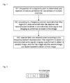
- the disclosure realizes a method for non-uniform sampling of a singularity point of a multi-channel SAR system. As shown in Fig. 1 , the method includes the following several steps.
- Vs is a platform flight speed
- N is the number of sub-channels
- ⁇ x is a distance between phase centers; actually, a PRF which is equivalent to uniform sampling cannot be used by the multi-channel SAR system in many cases due to reasons including design parameter limitation and wave position selection etc., thereby resulting in non-uniform sampling.
- Azimuth Doppler spectrum aliasing will be caused if processing is not performed, which results in a false target after imaging.
- Step 102 according to a frequency-domain reconstruction filter algorithm, data remained after the rejection are reconstructed to obtain a reconstructed echo signal and imaging is performed to obtain a first image; specifically, as shown in Fig. 3 , the data of the raw echoes of the first N-k channels which are remained after the rejection pass through an N-k-order frequency-domain reconstruction filter to obtain an echo signal equivalent to a single channel, and imaging processing is performed for the echo signal through an imaging algorithm to obtain the first image after the imaging; the N-k-order frequency-domain reconstruction filter performs an inverse operation ( P 1 ( f ), P 2 ( f ), ... P N-k ( f )) of the pre-filter for the data of the raw echoes of the first N-k channels.
- Step 103 rejected data are reconstructed according to the frequency-domain reconstruction filter algorithm to obtain a reconstructed echo signal, imaging is performed to obtain a second image, and the first image and the second image are superimposed to obtain a third image; specifically, as shown in Fig.
- the data of the raw echoes of k channels after the rejection and data of raw echoes of the last N-2k channels in the first N-k channels are combined into data of raw echoes of N-k channels, the data of the raw echoes of the N-k channels pass through the N-k-order frequency-domain reconstruction filter to obtain an echo signal equivalent to a single channel, and imaging processing is performed for the echo signal through an imaging algorithm to obtain the second imaged image; the first image and the second image are superimposed to obtain the third image; superimposing the first mage and the second image to obtain the third image may include: complex numeric data of the first image and complex numeric data of the second image are superimposed linearly to obtain the third image.
- the method of the disclosure can obtain a higher image SNR.
- SNR P t ⁇ x ⁇ G t ⁇ x ⁇ i ⁇ G r ⁇ x , j ⁇ i ⁇ ⁇ 3 ⁇ PRFuni ⁇ ⁇ ⁇ N ⁇ c 0 4 ⁇ 4 ⁇ ⁇ 3 ⁇ R 0 ⁇ ⁇ i 3 ⁇ L a ⁇ z ⁇ L ⁇ v s ⁇ sin ⁇ i ⁇ ⁇ b ⁇ f , B ⁇ d ⁇ k ⁇ B ⁇ r ⁇ T ⁇ F ⁇ ⁇ 0
- P tx is a peak power of antenna transmission
- G tx is a transmitting antenna gain
- G rx is a receiving antenna gain
- ⁇ is a carrier wavelength
- ⁇ a transmitted pulse width
- ⁇ is
- f is the frequency axis of azimuth
- B D is a processed Doppler bandwidth
- Formula (2) represents an influencing factor of a noise signal to the system noise after the noise signal passes through a reconstructed network.
- PRF N N - k ⁇ PRFuni , ⁇ bf,Bd results in sharp worsening of SNR due to the fact that singularity of the frequency-domain reconstruction filter becomes to be unlimitedly amplified;
- Noise 2 E ⁇ 4 ⁇ n 1 + ⁇ + n N - k 2 + n N - n 1 - ⁇ - n k 2 + n N - n 1 - ⁇ - n k ⁇ n 1 + ⁇ + n N - k
- the SNR 3 of the third image is higher than the SNR 2 of the first image.
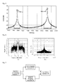
- Fig. 4 shows a schematic diagram illustrating system azimuth fuzzy simulation data of the third image and the first image, wherein the abscissa represents the PRF and the ordinate represents the Azimuth Ambiguity-to-Signal Ratio (AASR).
- the curve formed by squares is the system azimuth fuzzy simulation data of the first image and the curve formed by circles is the system azimuth fuzzy simulation data of the third image.
- the peaks pointed by the arrows are the positions of the singularity points. It can be seen that the system azimuth fuzzy simulation data of the third image are greatly reduced at the positions of the singularity points.
- Fig. 5 shows a schematic diagram illustrating system sensitivity simulation data of the third image and the first image, wherein the abscissa represents the PRF and the ordinate represents the system sensitivity Noise Equivalent Sigma Zero (NESZ).
- the curve formed by squares is the system sensitivity simulation data of the first image and the curve formed by circles is the system sensitivity simulation data of the third image.
- the peaks pointed by the arrows are the positions of the singularity points. It can be seen that the system sensitivity simulation data of the third image are effectively improved around the positions of the singularity points.
- Fig. 6 is shows a single-point target analysis (azimuth section).
- Fig. (a) represents an imaging result of the first image.
- the abscissa represents a range in azimuth and the ordinate represents a normalized magnitude. It can be seen that the imaging effect is bad, and there are false targets with extremely high magnitudes, which greatly affects the imaging quality.
- Fig. (b) represents an imaging result of the third image, and the false targets are inhibited perfectly.
- the disclosure further provides a device for non-uniform sampling of a singularity point of a SAR system.
- the device includes: a rejection processing module 21, a first imaging module 22, a second imaging module 23 and a synthesis module 24, wherein the rejection processing module 21 is configured to determine the position of a singularity point, perform rejection of data for raw echoes of multiple channels, transmit data remained after the rejection to the first imaging module 22 and transmit rejected data to the second imaging module 23; the first imaging module 22 is configured to, according to a frequency-domain reconstruction filter algorithm, reconstruct the data remained after the rejection to obtain a reconstructed echo signal and perform imaging to obtain a first image; the second imaging module 23 is configured to reconstruct the rejected data according to a frequency-domain reconstruction filter algorithm to obtain a reconstructed echo signal, and perform imaging to obtain a second image; and the synthesis module 24 is configured to superimpose the first image and the second image to obtain a third image.
- the first imaging module 22 is specifically configured to pass the data of the raw echoes of the first N-k channels, which are remained after the rejection, through an N-k-order frequency-domain reconstruction filter to obtain an echo signal equivalent to a single channel, and perform imaging processing for the echo signal through an imaging algorithm to obtain the first imaged image.
- the second imaging module 23 is specifically configured to combine the data of the raw echoes of the k channels after the rejection and data of raw echoes of the last N-2k channels in the first N-k channels into the data of the raw echoes of the N-k channels, pass the data of the raw echoes of the N-k channels through the N-k-order frequency-domain reconstruction filter to obtain an echo signal equivalent to a single channel, and perform imaging processing for the echo signal through an imaging algorithm to obtain the second imaged image.
Landscapes
- Engineering & Computer Science (AREA)
- Remote Sensing (AREA)
- Radar, Positioning & Navigation (AREA)
- Physics & Mathematics (AREA)
- Signal Processing (AREA)
- Electromagnetism (AREA)
- Computer Networks & Wireless Communication (AREA)
- General Physics & Mathematics (AREA)
- Radar Systems Or Details Thereof (AREA)
- Image Processing (AREA)
Description
- The disclosure relates to a multi-channel non-uniform sampling reconstruction technology, and more particularly to a method and a device for non-uniform sampling of a singularity point of a multi-channel Synthetic-Aperture Radar (SAR) system.
- Multi-channel SAR technology, which is a key technology to resolve the contradiction between SAR azimuth resolution and imaging bandwidth, is of great significance for the development and application of SARs.
- The main technical problem existing in a multi-channel SAR system is that sampling uniformity may be caused in the case that a Pulse Repetition Frequency (PRF) deviates from uniform sampling. Generally, non-uniform sampling reconstruction can be realized through a frequency-domain reconstruction filter. However, for special PRF positions, the frequency-domain reconstruction filter may fail due to the existence of a singularity point, thus resulting in a reconstruction failure.
- N. Gebert et al. describe in "Digital Beamforming on Receive: Techniques and Optimization Strategies for High-Resolution Wide-Swath SAR Imaging" (IEEE Transactions on Aerospace and Electronic Systems, Vol. 45, Vol. 2, pp. 564-592) a method to handle singularities in multi-channel SAR. The singularities are treated either through a pre-beam shaping network or adapted beamforming.
-
FR 2,914,432 - In view of this, the main purpose of the disclosure is to provide a method and a device for non-uniform sampling of a singularity point of a multi-channel SAR system to effectively solve the problem of a singularity point in multi-channel non-uniform sampling reconstruction.
- To realize the purpose above, the technical solution of the disclosure is implemented by the following way.
- The disclosure provides a method for non-uniform sampling of a singularity point of a multi-channel SAR system. The method includes:
- a position of a singularity point is determined and rejection of data is performed for raw echoes of multiple channels;
- according to a frequency-domain reconstruction filter algorithm, data remained after the rejection are reconstructed to obtain a reconstructed echo signal and imaging is performed to obtain a first image; and
- rejected data are reconstructed according to a frequency-domain reconstruction filter algorithm to obtain a reconstructed echo signal, imaging is performed to obtain a second image, and the first image and the second image are superimposed to obtain a third image.
- In the solution above, the step of determining the position of the singularity point and performing the rejection of data for the raw echoes of multiple channels may be that: a multi-channel SAR system performs PRF calculation for acquired raw echo data; when PRF satisfies

- In the solution above, the step of reconstructing the data remained after the rejection according to the frequency-domain reconstruction filter algorithm to obtain the reconstructed echo signal and performing the imaging to obtain the first image may be that:
- the data of the raw echoes of the first N-k channels, which are remained after the rejection, pass through an N-k-order frequency-domain reconstruction filter to obtain an echo signal equivalent to a single channel, and imaging processing is performed for the echo signal through an imaging algorithm to obtain the first image after the imaging.
- In the solution above, the step of reconstructing the rejected data according to the frequency-domain reconstruction filter algorithm to obtain the reconstructed echo signal and performing the imaging to obtain the second image may be that:
- data of raw echoes of k channels after the rejection and data of raw echoes of last N-2k channels in the first N-k channels are combined into data of raw echoes of N-k channels, the data of the raw echoes of the N-k channels pass through the N-k-order frequency-domain reconstruction filter to obtain an echo signal equivalent to a single channel, and imaging processing is performed for the echo signal through an imaging algorithm to obtain the second image after the imaging.
- A device for non-uniform sampling of a singularity point of a multi-channel SAR system is provided by the disclosure. The device includes: a rejection processing module, a first imaging module, a second imaging module and a synthesis module, wherein
the rejection processing module is configured to determine a position of a singularity point, perform rejection of data for raw echoes of multiple channels, transmit data remained after the rejection to the first imaging module and transmit rejected data to the second imaging module;
the first imaging module is configured to, according to a frequency-domain reconstruction filter algorithm, reconstruct the data remained after the rejection to obtain a reconstructed echo signal and perform imaging to obtain a first image;
the second imaging module is configured to reconstruct the rejected data according to a frequency-domain reconstruction filter algorithm to obtain a reconstructed echo signal, and perform imaging to obtain a second image; and
the synthesis module is configured to superimpose the first image and the second image to obtain a third image. - In the solution above, the rejection processing module may be configured to perform PRF calculation for data of raw echoes; and when PRF satisfies

- In the solution above, the first imaging module may be configured to pass the data of the raw echoes of the first N-k channels, which are remained after the rejection, through an N-k-order frequency-domain reconstruction filter to obtain an echo signal equivalent to a single channel, and perform imaging processing for the echo signal through an imaging algorithm to obtain the first image after the imaging.
- In the solution above, the second imaging module may be configured to combine data of raw echoes of k channels after the rejection and data of raw echoes of last N-2k channels in the first N-k channels into data of raw echoes of N-k channels, pass the data of the raw echoes of the N-k channels through the N-k-order frequency-domain reconstruction filter to obtain an echo signal equivalent to a single channel, and perform imaging processing for the echo signal through an imaging algorithm to obtain the second image after the imaging.
- The disclosure provides a method and a device for non-uniform sampling of a singularity point of a multi-channel SAR system. The position of the singularity point is determined and rejection of data is performed for raw echoes of multiple channels. According to a frequency-domain reconstruction filter algorithm, data remained after the rejection are reconstructed to obtain a reconstructed echo signal and imaging is performed to obtain a first image. Rejected data are reconstructed according to a frequency-domain reconstruction filter algorithm to obtain a reconstructed echo signal, imaging is performed to obtain a second image, and the first image and the second image are superimposed to obtain a third image, thereby effectively solving the problem of a frequency-domain reconstruction filter failure caused by a singularity point and obtaining a higher image Signal to Noise Ratio (SNR) through image compensation.
-
-
Fig. 1 is a flowchart of a method for non-uniform sampling of a singularity point of a multi-channel SAR system of the disclosure; -
Fig. 2 is a schematic diagram illustrating rejection of data of raw echoes of multiple channels in an embodiment of the disclosure; -
Fig .3 is a schematic diagram illustrating reconstruction for data of raw echoes of multiple channels in an embodiment of the disclosure; -
Fig. 4 is a schematic diagram illustrating system azimuth fuzzy simulation data of a third image and a first image in an embodiment of the disclosure; -
Fig. 5 is a schematic diagram illustrating system sensitivity simulation data of a third image and a first image in an embodiment of the disclosure; -
Fig. 6 is a schematic diagram illustrating a single-point target analysis result of a third image and a first image in an embodiment of the disclosure; and -
Fig. 7 is a structural diagram of a device for non-uniform sampling of a singularity point of a multi-channel SAR system, which is further provided by the disclosure. - The basic idea of the disclosure is that the position of a singularity point is determined and rejection of data is performed for raw echoes of multiple channels. According to a frequency-domain reconstruction filter algorithm, data remained after the rejection are reconstructed to obtain a reconstructed echo signal and imaging is performed to obtain a first image. Rejected data are reconstructed according to a frequency-domain reconstruction filter algorithm to obtain a reconstructed echo signal, imaging is performed to obtain a second image, and the first image and the second image are superimposed to obtain a third image.
- The disclosure will be further described in details below through the accompanying drawings and embodiments.
- The disclosure realizes a method for non-uniform sampling of a singularity point of a multi-channel SAR system. As shown in
Fig. 1 , the method includes the following several steps. - Step 101: the position of a singularity point is determined and rejection of data is performed for raw echoes of multiple channels;
specifically, when a PRF satisfies
actually, a PRF which is equivalent to uniform sampling cannot be used by the multi-channel SAR system in many cases due to reasons including design parameter limitation and wave position selection etc., thereby resulting in non-uniform sampling. Azimuth Doppler spectrum aliasing will be caused if processing is not performed, which results in a false target after imaging. Through analysis, signals of multiple channels can be considered to be obtained by a pre-filter H(f) by using signals of a single channel. Band-limited signals of a single channel can be restored as long as inverse P(f) = H -1(f) of the pre-filter can be obtained. - The step includes: the multi-channel SAR system performs PRF calculation for acquired raw echo data; when PRF satisfies

Fig. 2 , it can be seen that the data of the raw echoes of the last k channels are not considered in this case, and the data of the raw echoes of the first N-k channels are signals of uniform sampling of N-k channels. - Step 102: according to a frequency-domain reconstruction filter algorithm, data remained after the rejection are reconstructed to obtain a reconstructed echo signal and imaging is performed to obtain a first image;
specifically, as shown inFig. 3 , the data of the raw echoes of the first N-k channels which are remained after the rejection pass through an N-k-order frequency-domain reconstruction filter to obtain an echo signal equivalent to a single channel, and imaging processing is performed for the echo signal through an imaging algorithm to obtain the first image after the imaging; the N-k-order frequency-domain reconstruction filter performs an inverse operation (P 1(f), P 2(f), ... P N-k(f)) of the pre-filter for the data of the raw echoes of the first N-k channels. - Step 103: rejected data are reconstructed according to the frequency-domain reconstruction filter algorithm to obtain a reconstructed echo signal, imaging is performed to obtain a second image, and the first image and the second image are superimposed to obtain a third image;
specifically, as shown inFig. 3 , the data of the raw echoes of k channels after the rejection and data of raw echoes of the last N-2k channels in the first N-k channels are combined into data of raw echoes of N-k channels, the data of the raw echoes of the N-k channels pass through the N-k-order frequency-domain reconstruction filter to obtain an echo signal equivalent to a single channel, and imaging processing is performed for the echo signal through an imaging algorithm to obtain the second imaged image; the first image and the second image are superimposed to obtain the third image;
superimposing the first mage and the second image to obtain the third image may include: complex numeric data of the first image and complex numeric data of the second image are superimposed linearly to obtain the third image. - By comparing the SNR of the first image with that of the second image as below, the method of the disclosure can obtain a higher image SNR.
- The rejection of channel data is equivalent to the case that part of the antennae are not used, which may cause a loss to the system SNR. Considering the SNR after system imaging, the SNR after imaging is:

where Ptx is a peak power of antenna transmission, Gtx is a transmitting antenna gain, Grx is a receiving antenna gain, λ is a carrier wavelength, τ is a transmitted pulse width, σ is a backscattering coefficient, C0 is a velocity of light, R0 is a slant range, Laz is the integration loss of azimuth, L is a system loss, Br is a transmission bandwidth, T is a system temperature, F is a receiver noise coefficient and Θ i is a satellite incidence.
where f is the frequency axis of azimuth, BD is a processed Doppler bandwidth; - Formula (2) represents an influencing factor of a noise signal to the system noise after the noise signal passes through a reconstructed network. When

the SNR2 of the first image obtained by the data of the raw echoes of the first N-k channels is:
- here, provided that N - k ≥ k;
- provided that the magnitude of the first image is P, and the energy spectrum PS,1 is:

- ni is set as noise signals of N channels, i=1,2....N, and the noise power spectrum Noise1 of the first image is:

- since white noises of the system are uncorrelated to each other and have the same power spectrum, it can be obtained that:

where
- After the first image and the second image are superimposed, the magnitude of the third image after the superimposing is also P because the imaging region is not changed, and the energy spectrum PS,2 after the superimposing is:

- The noise power spectrum Noise2 after the superimposing is:

- Since the noises among the channels are uncorrelated to each other, Formula (9) is expanded to obtain:

- Combining (3), (4), (6), (8) and (10), the SNR3 of the third image is:

- Since k ≥ 1,

-
Fig. 4 shows a schematic diagram illustrating system azimuth fuzzy simulation data of the third image and the first image, wherein the abscissa represents the PRF and the ordinate represents the Azimuth Ambiguity-to-Signal Ratio (AASR). The curve formed by squares is the system azimuth fuzzy simulation data of the first image and the curve formed by circles is the system azimuth fuzzy simulation data of the third image. The peaks pointed by the arrows are the positions of the singularity points. It can be seen that the system azimuth fuzzy simulation data of the third image are greatly reduced at the positions of the singularity points. -
Fig. 5 shows a schematic diagram illustrating system sensitivity simulation data of the third image and the first image, wherein the abscissa represents the PRF and the ordinate represents the system sensitivity Noise Equivalent Sigma Zero (NESZ). The curve formed by squares is the system sensitivity simulation data of the first image and the curve formed by circles is the system sensitivity simulation data of the third image. The peaks pointed by the arrows are the positions of the singularity points. It can be seen that the system sensitivity simulation data of the third image are effectively improved around the positions of the singularity points. -
Fig. 6 is shows a single-point target analysis (azimuth section). Fig. (a) represents an imaging result of the first image. The abscissa represents a range in azimuth and the ordinate represents a normalized magnitude. It can be seen that the imaging effect is bad, and there are false targets with extremely high magnitudes, which greatly affects the imaging quality. Fig. (b) represents an imaging result of the third image, and the false targets are inhibited perfectly. - To realize the method above, the disclosure further provides a device for non-uniform sampling of a singularity point of a SAR system. As shown in
Fig. 7 , the device includes: arejection processing module 21, afirst imaging module 22, asecond imaging module 23 and asynthesis module 24, wherein
therejection processing module 21 is configured to determine the position of a singularity point, perform rejection of data for raw echoes of multiple channels, transmit data remained after the rejection to thefirst imaging module 22 and transmit rejected data to thesecond imaging module 23;
thefirst imaging module 22 is configured to, according to a frequency-domain reconstruction filter algorithm, reconstruct the data remained after the rejection to obtain a reconstructed echo signal and perform imaging to obtain a first image;
thesecond imaging module 23 is configured to reconstruct the rejected data according to a frequency-domain reconstruction filter algorithm to obtain a reconstructed echo signal, and perform imaging to obtain a second image; and
thesynthesis module 24 is configured to superimpose the first image and the second image to obtain a third image. - The
rejection processing module 21 is specifically configured to perform PRF calculation for data of raw echoes, and when PRF satisfies
first imaging module 22 and transmit data of raw echoes of the last k channels to thesecond imaging module 23, where N is the number of sub-channels, k=1, 2, ..., N-1, PRFuni is the PRF when the acquired raw echo data are sampled uniformly. - The
first imaging module 22 is specifically configured to pass the data of the raw echoes of the first N-k channels, which are remained after the rejection, through an N-k-order frequency-domain reconstruction filter to obtain an echo signal equivalent to a single channel, and perform imaging processing for the echo signal through an imaging algorithm to obtain the first imaged image. - The
second imaging module 23 is specifically configured to combine the data of the raw echoes of the k channels after the rejection and data of raw echoes of the last N-2k channels in the first N-k channels into the data of the raw echoes of the N-k channels, pass the data of the raw echoes of the N-k channels through the N-k-order frequency-domain reconstruction filter to obtain an echo signal equivalent to a single channel, and perform imaging processing for the echo signal through an imaging algorithm to obtain the second imaged image. - The above are only preferred embodiments of the disclosure and not used for limiting the protection scope of the disclosure.
Claims (8)
- A method for non-uniform sampling of a singularity point of a multi-channel Synthetic-Aperture Radar, SAR, system, the singularity point originating from non-uniform Pulse Repetition Frequency, PRF, comprising:determining (101) a position of a singularity point and performing rejection of data for raw echoes of multiple channels;according to a frequency-domain reconstruction filter algorithm, reconstructing (102) data remained after the rejection to obtain a reconstructed echo signal and performing imaging to obtain a first image; andreconstructing (103) rejected data according to a frequency-domain reconstruction filter algorithm to obtain a reconstructed echo signal, performing imaging to obtain a second image, and superimposing the first image and the second image to obtain a third image.
- The method according to claim 1, wherein the step of determining the position of the singularity point and performing the rejection of data for the raw echoes of multiple channels is that: a multi-channel SAR system performs Pulse Repetition Frequency, PRF, calculation for acquired raw echo data; when PRF satisfies

- The method according to claim 2, wherein the step of reconstructing the data remained after the rejection according to the frequency-domain reconstruction filter algorithm to obtain the reconstructed echo signal and performing the imaging to obtain the first image is that:the data of the raw echoes of the first N-k channels, which are remained after the rejection, pass through an N-k-order frequency-domain reconstruction filter to obtain an echo signal equivalent to a single channel, and imaging processing is performed for the echo signal through an imaging algorithm to obtain the first image after the imaging.
- The method according to claim 3, wherein the step of reconstructing the rejected data according to the frequency-domain reconstruction filter algorithm to obtain the reconstructed echo signal and performing the imaging to obtain the second image is that:data of raw echoes of k channels after the rejection and data of raw echoes of last N-2k channels in the first N-k channels are combined into data of raw echoes of N-k channels, the data of the raw echoes of the N-k channels pass through the N-k-order frequency-domain reconstruction filter to obtain an echo signal equivalent to a single channel, and imaging processing is performed for the echo signal through an imaging algorithm to obtain the second image after the imaging.
- A device for non-uniform sampling of a singularity point of a multi-channel Synthetic-Aperture Radar, SAR, system, the singularity point originating from non-uniform Pulse Repetition Frequency, PRF, comprising a rejection processing module (21), a first imaging module (22), a second imaging module (23) and a synthesis module (24), wherein
the rejection processing module (21) is configured to determine a position of a singularity point, perform rejection of data for raw echoes of multiple channels, transmit data remained after the rejection to the first imaging module and transmit rejected data to the second imaging module;
the first imaging module (22) is configured to, according to a frequency-domain reconstruction filter algorithm, reconstruct the data remained after the rejection to obtain a reconstructed echo signal and perform imaging to obtain a first image;
the second imaging module (23) is configured to reconstruct the rejected data according to a frequency-domain reconstruction filter algorithm to obtain a reconstructed echo signal, and perform imaging to obtain a second image; and
the synthesis module (24) is configured to superimpose the first image and the second image to obtain a third image. - The device according to claim 5, wherein the rejection processing module (21) is configured to perform Pulse Repetition Frequency, PRF, calculation for data of raw echoes, and when PRF satisfies

- The device according to claim 6, wherein the first imaging module (22) is configured to pass the data of the raw echoes of the first N-k channels, which are remained after the rejection, through an N-k-order frequency-domain reconstruction filter to obtain an echo signal equivalent to a single channel, and perform imaging processing for the echo signal through an imaging algorithm to obtain the first image after the imaging.
- The device according to claim 7, wherein the second imaging module (23) is configured to combine data of raw echoes of k channels after the rejection and data of raw echoes of last N-2k channels in the first N-k channels into data of raw echoes of N-k channels, pass the data of the raw echoes of the N-k channels through the N-k-order frequency-domain reconstruction filter to obtain an echo signal equivalent to a single channel, and perform imaging processing for the echo signal through an imaging algorithm to obtain the second image after the imaging.
Applications Claiming Priority (1)
| Application Number | Priority Date | Filing Date | Title |
|---|---|---|---|
| CN201310058998.6A CN103323818B (en) | 2013-02-25 | 2013-02-25 | Method and device for non-uniformly sampling singular points of multichannel synthetic aperture radar system |
Publications (3)
| Publication Number | Publication Date |
|---|---|
| EP2662704A2 EP2662704A2 (en) | 2013-11-13 |
| EP2662704A3 EP2662704A3 (en) | 2014-02-26 |
| EP2662704B1 true EP2662704B1 (en) | 2016-01-13 |
Family
ID=48951380
Family Applications (1)
| Application Number | Title | Priority Date | Filing Date |
|---|---|---|---|
| EP13180104.5A Not-in-force EP2662704B1 (en) | 2013-02-25 | 2013-08-12 | Method and device for non-uniform sampling of singularity point of multi-channel synthetic-aperture radar (SAR) system |
Country Status (2)
| Country | Link |
|---|---|
| EP (1) | EP2662704B1 (en) |
| CN (1) | CN103323818B (en) |
Cited By (6)
| Publication number | Priority date | Publication date | Assignee | Title |
|---|---|---|---|---|
| US10615513B2 (en) | 2015-06-16 | 2020-04-07 | Urthecast Corp | Efficient planar phased array antenna assembly |
| US10871561B2 (en) | 2015-03-25 | 2020-12-22 | Urthecast Corp. | Apparatus and methods for synthetic aperture radar with digital beamforming |
| US10955546B2 (en) | 2015-11-25 | 2021-03-23 | Urthecast Corp. | Synthetic aperture radar imaging apparatus and methods |
| US11378682B2 (en) | 2017-05-23 | 2022-07-05 | Spacealpha Insights Corp. | Synthetic aperture radar imaging apparatus and methods for moving targets |
| US11506778B2 (en) | 2017-05-23 | 2022-11-22 | Spacealpha Insights Corp. | Synthetic aperture radar imaging apparatus and methods |
| US11525910B2 (en) | 2017-11-22 | 2022-12-13 | Spacealpha Insights Corp. | Synthetic aperture radar apparatus and methods |
Families Citing this family (8)
| Publication number | Priority date | Publication date | Assignee | Title |
|---|---|---|---|---|
| CN104076360B (en) * | 2014-07-04 | 2016-08-17 | 西安电子科技大学 | The sparse target imaging method of two-dimensional SAR based on compressed sensing |
| CN105425237B (en) * | 2015-12-10 | 2018-01-09 | 上海机电工程研究所 | Multichannel SAR system channel equalization methods based on sample selection |
| CN105807278B (en) * | 2016-03-02 | 2018-11-23 | 中国科学院电子学研究所 | A kind of SAR echo signal goes rectangle method |
| CN107942331B (en) * | 2017-11-28 | 2021-06-08 | 西安电子科技大学 | Channel Bias Estimation Method for Multi-channel SAR System Based on Spectral Analysis |
| CN112130147B (en) * | 2020-08-31 | 2022-09-06 | 北京空间飞行器总体设计部 | An imaging wave position determination method based on the position information of sea and land targets |
| CN113985359B (en) * | 2021-10-12 | 2024-12-24 | 航天恒星科技有限公司 | An airborne SAR echo receiving system and method based on non-uniform equivalent bandpass sampling |
| CN116879890A (en) * | 2023-05-26 | 2023-10-13 | 北京理工雷科空天信息技术有限公司 | Multi-channel SAR full scene data continuous imaging method |
| CN116660899B (en) * | 2023-08-01 | 2023-10-13 | 西安电子科技大学 | Near-field target ISAR imaging system and device based on FPGA+DSP |
Family Cites Families (3)
| Publication number | Priority date | Publication date | Assignee | Title |
|---|---|---|---|---|
| CN101078769B (en) * | 2006-05-25 | 2010-06-16 | 中国科学院中国遥感卫星地面站 | One-time all-polarization synthetic aperture radar image inverse method for digital elevation model |
| ITRM20070399A1 (en) * | 2007-07-19 | 2009-01-20 | Consiglio Nazionale Ricerche | METHOD OF PROCESSING OF THE DATA BY MEANS OF SYNTHETIC OPENING RADARS (SYNTHETIC APERTURE RADAR - SAR) AND RELATIVE SENSING SYSTEM. |
| CN101685155B (en) * | 2008-09-27 | 2012-08-29 | 中国科学院电子学研究所 | Method of optimizing interference coefficient of coherence on the basis of polarimetric synthetic aperture radar (SAR) |
-
2013
- 2013-02-25 CN CN201310058998.6A patent/CN103323818B/en active Active
- 2013-08-12 EP EP13180104.5A patent/EP2662704B1/en not_active Not-in-force
Cited By (7)
| Publication number | Priority date | Publication date | Assignee | Title |
|---|---|---|---|---|
| US10871561B2 (en) | 2015-03-25 | 2020-12-22 | Urthecast Corp. | Apparatus and methods for synthetic aperture radar with digital beamforming |
| US10615513B2 (en) | 2015-06-16 | 2020-04-07 | Urthecast Corp | Efficient planar phased array antenna assembly |
| US10955546B2 (en) | 2015-11-25 | 2021-03-23 | Urthecast Corp. | Synthetic aperture radar imaging apparatus and methods |
| US11754703B2 (en) | 2015-11-25 | 2023-09-12 | Spacealpha Insights Corp. | Synthetic aperture radar imaging apparatus and methods |
| US11378682B2 (en) | 2017-05-23 | 2022-07-05 | Spacealpha Insights Corp. | Synthetic aperture radar imaging apparatus and methods for moving targets |
| US11506778B2 (en) | 2017-05-23 | 2022-11-22 | Spacealpha Insights Corp. | Synthetic aperture radar imaging apparatus and methods |
| US11525910B2 (en) | 2017-11-22 | 2022-12-13 | Spacealpha Insights Corp. | Synthetic aperture radar apparatus and methods |
Also Published As
| Publication number | Publication date |
|---|---|
| EP2662704A2 (en) | 2013-11-13 |
| EP2662704A3 (en) | 2014-02-26 |
| CN103323818A (en) | 2013-09-25 |
| CN103323818B (en) | 2015-06-10 |
Similar Documents
| Publication | Publication Date | Title |
|---|---|---|
| EP2662704A2 (en) | Method and device for non-uniform sampling of singularity point of multi-channel synthetic-aperture radar (SAR) system | |
| CN104166141B (en) | Method for designing multiple-input-multiple-output synthetic aperture radar system on basis of sub-band synthesis | |
| Bordoni et al. | Ambiguity suppression by azimuth phase coding in multichannel SAR systems | |
| EP3012658B1 (en) | Method and device for implementing sar imaging | |
| CN102955150B (en) | SAR (synthetic aperture radar) direction ambiguity suppression method based on antenna main lobe dominance intensity constraint | |
| CN103954938A (en) | Multi-sub-band reception synthetic method for SAR echo signals | |
| EP3373036A1 (en) | Azimuth signal reconstruction method and device for synthetic aperture radar | |
| CN102445691A (en) | Multichannel spaceborne synthetic aperture radar azimuth spectrum sparse reconstruction method | |
| CN108931766B (en) | Non-uniform STAP interference target filtering method based on sparse reconstruction | |
| Chen et al. | Implementation of an adaptive wideband digital array radar processor using subbanding for enhanced jamming cancellation | |
| CN105158759A (en) | HRWS SAR channel phase deviation correction method based on clutter cancellation | |
| CN106324598A (en) | Multichannel sub-band signal equalization and synchronization method and system | |
| CN116736245A (en) | A phase compensation method, device, equipment and storage medium | |
| Yang et al. | Range ambiguity suppression by azimuth phase coding in multichannel SAR systems | |
| US12280895B1 (en) | Azimuth ambiguity suppression method for spaceborne SAR in spatially non-uniform sampling | |
| Luo et al. | Influences of channel errors and interference on the OFDM-MIMO SAR | |
| Gabriel | Superresolution techniques and ISAR imaging | |
| Mulinde et al. | Experimental validation of direction of arrival estimation for high chirp‐rate linear frequency modulated radar signals | |
| CN108132460B (en) | Pulse compression compensation algorithm based on frequency domain channel equalization | |
| CN104391287A (en) | Aerial maneuvering target detecting method based on tertiary phase transformation and virtual phase function | |
| US9945941B1 (en) | Simultaneous continuous wave signals | |
| Bertl et al. | Demonstration of digital beamforming in elevation for spaceborne synthetic aperture radar | |
| Zhou et al. | An Efficient HRWS Sar Reconstruction Method Based on Frequency Domain Back Projection | |
| Zhong et al. | ScanSAR radiometric correction and ANALYSIS of GaoFen-3 | |
| CN116718995B (en) | Azimuth multi-channel SAR phase error correction method based on minimum spectral difference |
Legal Events
| Date | Code | Title | Description |
|---|---|---|---|
| PUAI | Public reference made under article 153(3) epc to a published international application that has entered the european phase |
Free format text: ORIGINAL CODE: 0009012 |
|
| AK | Designated contracting states |
Kind code of ref document: A2 Designated state(s): AL AT BE BG CH CY CZ DE DK EE ES FI FR GB GR HR HU IE IS IT LI LT LU LV MC MK MT NL NO PL PT RO RS SE SI SK SM TR |
|
| AX | Request for extension of the european patent |
Extension state: BA ME |
|
| PUAL | Search report despatched |
Free format text: ORIGINAL CODE: 0009013 |
|
| AK | Designated contracting states |
Kind code of ref document: A3 Designated state(s): AL AT BE BG CH CY CZ DE DK EE ES FI FR GB GR HR HU IE IS IT LI LT LU LV MC MK MT NL NO PL PT RO RS SE SI SK SM TR |
|
| AX | Request for extension of the european patent |
Extension state: BA ME |
|
| RIC1 | Information provided on ipc code assigned before grant |
Ipc: G01S 13/90 20060101AFI20140121BHEP |
|
| 17P | Request for examination filed |
Effective date: 20140313 |
|
| RBV | Designated contracting states (corrected) |
Designated state(s): AL AT BE BG CH CY CZ DE DK EE ES FI FR GB GR HR HU IE IS IT LI LT LU LV MC MK MT NL NO PL PT RO RS SE SI SK SM TR |
|
| GRAP | Despatch of communication of intention to grant a patent |
Free format text: ORIGINAL CODE: EPIDOSNIGR1 |
|
| INTG | Intention to grant announced |
Effective date: 20150924 |
|
| GRAS | Grant fee paid |
Free format text: ORIGINAL CODE: EPIDOSNIGR3 |
|
| GRAA | (expected) grant |
Free format text: ORIGINAL CODE: 0009210 |
|
| AK | Designated contracting states |
Kind code of ref document: B1 Designated state(s): AL AT BE BG CH CY CZ DE DK EE ES FI FR GB GR HR HU IE IS IT LI LT LU LV MC MK MT NL NO PL PT RO RS SE SI SK SM TR |
|
| REG | Reference to a national code |
Ref country code: GB Ref legal event code: FG4D |
|
| REG | Reference to a national code |
Ref country code: CH Ref legal event code: EP |
|
| REG | Reference to a national code |
Ref country code: IE Ref legal event code: FG4D |
|
| REG | Reference to a national code |
Ref country code: AT Ref legal event code: REF Ref document number: 770890 Country of ref document: AT Kind code of ref document: T Effective date: 20160215 |
|
| REG | Reference to a national code |
Ref country code: DE Ref legal event code: R096 Ref document number: 602013004592 Country of ref document: DE |
|
| REG | Reference to a national code |
Ref country code: LT Ref legal event code: MG4D |
|
| REG | Reference to a national code |
Ref country code: NL Ref legal event code: MP Effective date: 20160113 |
|
| REG | Reference to a national code |
Ref country code: AT Ref legal event code: MK05 Ref document number: 770890 Country of ref document: AT Kind code of ref document: T Effective date: 20160113 |
|
| PG25 | Lapsed in a contracting state [announced via postgrant information from national office to epo] |
Ref country code: NL Free format text: LAPSE BECAUSE OF FAILURE TO SUBMIT A TRANSLATION OF THE DESCRIPTION OR TO PAY THE FEE WITHIN THE PRESCRIBED TIME-LIMIT Effective date: 20160113 |
|
| PG25 | Lapsed in a contracting state [announced via postgrant information from national office to epo] |
Ref country code: IT Free format text: LAPSE BECAUSE OF FAILURE TO SUBMIT A TRANSLATION OF THE DESCRIPTION OR TO PAY THE FEE WITHIN THE PRESCRIBED TIME-LIMIT Effective date: 20160113 Ref country code: ES Free format text: LAPSE BECAUSE OF FAILURE TO SUBMIT A TRANSLATION OF THE DESCRIPTION OR TO PAY THE FEE WITHIN THE PRESCRIBED TIME-LIMIT Effective date: 20160113 Ref country code: FI Free format text: LAPSE BECAUSE OF FAILURE TO SUBMIT A TRANSLATION OF THE DESCRIPTION OR TO PAY THE FEE WITHIN THE PRESCRIBED TIME-LIMIT Effective date: 20160113 Ref country code: HR Free format text: LAPSE BECAUSE OF FAILURE TO SUBMIT A TRANSLATION OF THE DESCRIPTION OR TO PAY THE FEE WITHIN THE PRESCRIBED TIME-LIMIT Effective date: 20160113 Ref country code: GR Free format text: LAPSE BECAUSE OF FAILURE TO SUBMIT A TRANSLATION OF THE DESCRIPTION OR TO PAY THE FEE WITHIN THE PRESCRIBED TIME-LIMIT Effective date: 20160414 Ref country code: NO Free format text: LAPSE BECAUSE OF FAILURE TO SUBMIT A TRANSLATION OF THE DESCRIPTION OR TO PAY THE FEE WITHIN THE PRESCRIBED TIME-LIMIT Effective date: 20160413 |
|
| PG25 | Lapsed in a contracting state [announced via postgrant information from national office to epo] |
Ref country code: PT Free format text: LAPSE BECAUSE OF FAILURE TO SUBMIT A TRANSLATION OF THE DESCRIPTION OR TO PAY THE FEE WITHIN THE PRESCRIBED TIME-LIMIT Effective date: 20160513 Ref country code: IS Free format text: LAPSE BECAUSE OF FAILURE TO SUBMIT A TRANSLATION OF THE DESCRIPTION OR TO PAY THE FEE WITHIN THE PRESCRIBED TIME-LIMIT Effective date: 20160513 Ref country code: LT Free format text: LAPSE BECAUSE OF FAILURE TO SUBMIT A TRANSLATION OF THE DESCRIPTION OR TO PAY THE FEE WITHIN THE PRESCRIBED TIME-LIMIT Effective date: 20160113 Ref country code: LV Free format text: LAPSE BECAUSE OF FAILURE TO SUBMIT A TRANSLATION OF THE DESCRIPTION OR TO PAY THE FEE WITHIN THE PRESCRIBED TIME-LIMIT Effective date: 20160113 Ref country code: AT Free format text: LAPSE BECAUSE OF FAILURE TO SUBMIT A TRANSLATION OF THE DESCRIPTION OR TO PAY THE FEE WITHIN THE PRESCRIBED TIME-LIMIT Effective date: 20160113 Ref country code: SE Free format text: LAPSE BECAUSE OF FAILURE TO SUBMIT A TRANSLATION OF THE DESCRIPTION OR TO PAY THE FEE WITHIN THE PRESCRIBED TIME-LIMIT Effective date: 20160113 Ref country code: PL Free format text: LAPSE BECAUSE OF FAILURE TO SUBMIT A TRANSLATION OF THE DESCRIPTION OR TO PAY THE FEE WITHIN THE PRESCRIBED TIME-LIMIT Effective date: 20160113 Ref country code: RS Free format text: LAPSE BECAUSE OF FAILURE TO SUBMIT A TRANSLATION OF THE DESCRIPTION OR TO PAY THE FEE WITHIN THE PRESCRIBED TIME-LIMIT Effective date: 20160113 |
|
| REG | Reference to a national code |
Ref country code: DE Ref legal event code: R097 Ref document number: 602013004592 Country of ref document: DE |
|
| PG25 | Lapsed in a contracting state [announced via postgrant information from national office to epo] |
Ref country code: DK Free format text: LAPSE BECAUSE OF FAILURE TO SUBMIT A TRANSLATION OF THE DESCRIPTION OR TO PAY THE FEE WITHIN THE PRESCRIBED TIME-LIMIT Effective date: 20160113 Ref country code: EE Free format text: LAPSE BECAUSE OF FAILURE TO SUBMIT A TRANSLATION OF THE DESCRIPTION OR TO PAY THE FEE WITHIN THE PRESCRIBED TIME-LIMIT Effective date: 20160113 |
|
| PLBE | No opposition filed within time limit |
Free format text: ORIGINAL CODE: 0009261 |
|
| STAA | Information on the status of an ep patent application or granted ep patent |
Free format text: STATUS: NO OPPOSITION FILED WITHIN TIME LIMIT |
|
| PG25 | Lapsed in a contracting state [announced via postgrant information from national office to epo] |
Ref country code: RO Free format text: LAPSE BECAUSE OF FAILURE TO SUBMIT A TRANSLATION OF THE DESCRIPTION OR TO PAY THE FEE WITHIN THE PRESCRIBED TIME-LIMIT Effective date: 20160113 Ref country code: SK Free format text: LAPSE BECAUSE OF FAILURE TO SUBMIT A TRANSLATION OF THE DESCRIPTION OR TO PAY THE FEE WITHIN THE PRESCRIBED TIME-LIMIT Effective date: 20160113 Ref country code: SM Free format text: LAPSE BECAUSE OF FAILURE TO SUBMIT A TRANSLATION OF THE DESCRIPTION OR TO PAY THE FEE WITHIN THE PRESCRIBED TIME-LIMIT Effective date: 20160113 Ref country code: CZ Free format text: LAPSE BECAUSE OF FAILURE TO SUBMIT A TRANSLATION OF THE DESCRIPTION OR TO PAY THE FEE WITHIN THE PRESCRIBED TIME-LIMIT Effective date: 20160113 |
|
| 26N | No opposition filed |
Effective date: 20161014 |
|
| PG25 | Lapsed in a contracting state [announced via postgrant information from national office to epo] |
Ref country code: BE Free format text: LAPSE BECAUSE OF FAILURE TO SUBMIT A TRANSLATION OF THE DESCRIPTION OR TO PAY THE FEE WITHIN THE PRESCRIBED TIME-LIMIT Effective date: 20160113 |
|
| PG25 | Lapsed in a contracting state [announced via postgrant information from national office to epo] |
Ref country code: SI Free format text: LAPSE BECAUSE OF FAILURE TO SUBMIT A TRANSLATION OF THE DESCRIPTION OR TO PAY THE FEE WITHIN THE PRESCRIBED TIME-LIMIT Effective date: 20160113 Ref country code: BG Free format text: LAPSE BECAUSE OF FAILURE TO SUBMIT A TRANSLATION OF THE DESCRIPTION OR TO PAY THE FEE WITHIN THE PRESCRIBED TIME-LIMIT Effective date: 20160413 |
|
| REG | Reference to a national code |
Ref country code: DE Ref legal event code: R119 Ref document number: 602013004592 Country of ref document: DE |
|
| PG25 | Lapsed in a contracting state [announced via postgrant information from national office to epo] |
Ref country code: MC Free format text: LAPSE BECAUSE OF FAILURE TO SUBMIT A TRANSLATION OF THE DESCRIPTION OR TO PAY THE FEE WITHIN THE PRESCRIBED TIME-LIMIT Effective date: 20160113 |
|
| REG | Reference to a national code |
Ref country code: CH Ref legal event code: PL |
|
| PG25 | Lapsed in a contracting state [announced via postgrant information from national office to epo] |
Ref country code: CH Free format text: LAPSE BECAUSE OF NON-PAYMENT OF DUE FEES Effective date: 20160831 Ref country code: LI Free format text: LAPSE BECAUSE OF NON-PAYMENT OF DUE FEES Effective date: 20160831 |
|
| REG | Reference to a national code |
Ref country code: FR Ref legal event code: ST Effective date: 20170428 |
|
| REG | Reference to a national code |
Ref country code: IE Ref legal event code: MM4A |
|
| PG25 | Lapsed in a contracting state [announced via postgrant information from national office to epo] |
Ref country code: IE Free format text: LAPSE BECAUSE OF NON-PAYMENT OF DUE FEES Effective date: 20160812 Ref country code: FR Free format text: LAPSE BECAUSE OF NON-PAYMENT OF DUE FEES Effective date: 20160831 Ref country code: DE Free format text: LAPSE BECAUSE OF NON-PAYMENT OF DUE FEES Effective date: 20170301 |
|
| PG25 | Lapsed in a contracting state [announced via postgrant information from national office to epo] |
Ref country code: LU Free format text: LAPSE BECAUSE OF NON-PAYMENT OF DUE FEES Effective date: 20160812 |
|
| GBPC | Gb: european patent ceased through non-payment of renewal fee |
Effective date: 20170812 |
|
| PG25 | Lapsed in a contracting state [announced via postgrant information from national office to epo] |
Ref country code: CY Free format text: LAPSE BECAUSE OF FAILURE TO SUBMIT A TRANSLATION OF THE DESCRIPTION OR TO PAY THE FEE WITHIN THE PRESCRIBED TIME-LIMIT Effective date: 20160113 Ref country code: HU Free format text: LAPSE BECAUSE OF FAILURE TO SUBMIT A TRANSLATION OF THE DESCRIPTION OR TO PAY THE FEE WITHIN THE PRESCRIBED TIME-LIMIT; INVALID AB INITIO Effective date: 20130812 |
|
| PG25 | Lapsed in a contracting state [announced via postgrant information from national office to epo] |
Ref country code: MK Free format text: LAPSE BECAUSE OF FAILURE TO SUBMIT A TRANSLATION OF THE DESCRIPTION OR TO PAY THE FEE WITHIN THE PRESCRIBED TIME-LIMIT Effective date: 20160113 Ref country code: MT Free format text: LAPSE BECAUSE OF NON-PAYMENT OF DUE FEES Effective date: 20160831 Ref country code: TR Free format text: LAPSE BECAUSE OF FAILURE TO SUBMIT A TRANSLATION OF THE DESCRIPTION OR TO PAY THE FEE WITHIN THE PRESCRIBED TIME-LIMIT Effective date: 20160113 |
|
| PG25 | Lapsed in a contracting state [announced via postgrant information from national office to epo] |
Ref country code: GB Free format text: LAPSE BECAUSE OF NON-PAYMENT OF DUE FEES Effective date: 20170812 |
|
| PG25 | Lapsed in a contracting state [announced via postgrant information from national office to epo] |
Ref country code: AL Free format text: LAPSE BECAUSE OF FAILURE TO SUBMIT A TRANSLATION OF THE DESCRIPTION OR TO PAY THE FEE WITHIN THE PRESCRIBED TIME-LIMIT Effective date: 20160113 |