EP2662587A1 - Electric brake device - Google Patents
Electric brake device Download PDFInfo
- Publication number
- EP2662587A1 EP2662587A1 EP11855063.1A EP11855063A EP2662587A1 EP 2662587 A1 EP2662587 A1 EP 2662587A1 EP 11855063 A EP11855063 A EP 11855063A EP 2662587 A1 EP2662587 A1 EP 2662587A1
- Authority
- EP
- European Patent Office
- Prior art keywords
- reaction force
- linear motion
- force receiving
- brake system
- electric brake
- Prior art date
- Legal status (The legal status is an assumption and is not a legal conclusion. Google has not performed a legal analysis and makes no representation as to the accuracy of the status listed.)
- Granted
Links
Images


Classifications
-
- F—MECHANICAL ENGINEERING; LIGHTING; HEATING; WEAPONS; BLASTING
- F16—ENGINEERING ELEMENTS AND UNITS; GENERAL MEASURES FOR PRODUCING AND MAINTAINING EFFECTIVE FUNCTIONING OF MACHINES OR INSTALLATIONS; THERMAL INSULATION IN GENERAL
- F16D—COUPLINGS FOR TRANSMITTING ROTATION; CLUTCHES; BRAKES
- F16D55/00—Brakes with substantially-radial braking surfaces pressed together in axial direction, e.g. disc brakes
- F16D55/02—Brakes with substantially-radial braking surfaces pressed together in axial direction, e.g. disc brakes with axially-movable discs or pads pressed against axially-located rotating members
- F16D55/22—Brakes with substantially-radial braking surfaces pressed together in axial direction, e.g. disc brakes with axially-movable discs or pads pressed against axially-located rotating members by clamping an axially-located rotating disc between movable braking members, e.g. movable brake discs or brake pads
- F16D55/224—Brakes with substantially-radial braking surfaces pressed together in axial direction, e.g. disc brakes with axially-movable discs or pads pressed against axially-located rotating members by clamping an axially-located rotating disc between movable braking members, e.g. movable brake discs or brake pads with a common actuating member for the braking members
- F16D55/225—Brakes with substantially-radial braking surfaces pressed together in axial direction, e.g. disc brakes with axially-movable discs or pads pressed against axially-located rotating members by clamping an axially-located rotating disc between movable braking members, e.g. movable brake discs or brake pads with a common actuating member for the braking members the braking members being brake pads
- F16D55/226—Brakes with substantially-radial braking surfaces pressed together in axial direction, e.g. disc brakes with axially-movable discs or pads pressed against axially-located rotating members by clamping an axially-located rotating disc between movable braking members, e.g. movable brake discs or brake pads with a common actuating member for the braking members the braking members being brake pads in which the common actuating member is moved axially, e.g. floating caliper disc brakes
-
- F—MECHANICAL ENGINEERING; LIGHTING; HEATING; WEAPONS; BLASTING
- F16—ENGINEERING ELEMENTS AND UNITS; GENERAL MEASURES FOR PRODUCING AND MAINTAINING EFFECTIVE FUNCTIONING OF MACHINES OR INSTALLATIONS; THERMAL INSULATION IN GENERAL
- F16D—COUPLINGS FOR TRANSMITTING ROTATION; CLUTCHES; BRAKES
- F16D65/00—Parts or details
- F16D65/14—Actuating mechanisms for brakes; Means for initiating operation at a predetermined position
- F16D65/16—Actuating mechanisms for brakes; Means for initiating operation at a predetermined position arranged in or on the brake
- F16D65/18—Actuating mechanisms for brakes; Means for initiating operation at a predetermined position arranged in or on the brake adapted for drawing members together, e.g. for disc brakes
-
- F—MECHANICAL ENGINEERING; LIGHTING; HEATING; WEAPONS; BLASTING
- F16—ENGINEERING ELEMENTS AND UNITS; GENERAL MEASURES FOR PRODUCING AND MAINTAINING EFFECTIVE FUNCTIONING OF MACHINES OR INSTALLATIONS; THERMAL INSULATION IN GENERAL
- F16D—COUPLINGS FOR TRANSMITTING ROTATION; CLUTCHES; BRAKES
- F16D66/00—Arrangements for monitoring working conditions, e.g. wear, temperature
- F16D2066/003—Position, angle or speed
-
- F—MECHANICAL ENGINEERING; LIGHTING; HEATING; WEAPONS; BLASTING
- F16—ENGINEERING ELEMENTS AND UNITS; GENERAL MEASURES FOR PRODUCING AND MAINTAINING EFFECTIVE FUNCTIONING OF MACHINES OR INSTALLATIONS; THERMAL INSULATION IN GENERAL
- F16D—COUPLINGS FOR TRANSMITTING ROTATION; CLUTCHES; BRAKES
- F16D66/00—Arrangements for monitoring working conditions, e.g. wear, temperature
- F16D2066/005—Force, torque, stress or strain
-
- F—MECHANICAL ENGINEERING; LIGHTING; HEATING; WEAPONS; BLASTING
- F16—ENGINEERING ELEMENTS AND UNITS; GENERAL MEASURES FOR PRODUCING AND MAINTAINING EFFECTIVE FUNCTIONING OF MACHINES OR INSTALLATIONS; THERMAL INSULATION IN GENERAL
- F16D—COUPLINGS FOR TRANSMITTING ROTATION; CLUTCHES; BRAKES
- F16D2121/00—Type of actuator operation force
- F16D2121/18—Electric or magnetic
- F16D2121/24—Electric or magnetic using motors
-
- F—MECHANICAL ENGINEERING; LIGHTING; HEATING; WEAPONS; BLASTING
- F16—ENGINEERING ELEMENTS AND UNITS; GENERAL MEASURES FOR PRODUCING AND MAINTAINING EFFECTIVE FUNCTIONING OF MACHINES OR INSTALLATIONS; THERMAL INSULATION IN GENERAL
- F16D—COUPLINGS FOR TRANSMITTING ROTATION; CLUTCHES; BRAKES
- F16D2125/00—Components of actuators
- F16D2125/18—Mechanical mechanisms
- F16D2125/20—Mechanical mechanisms converting rotation to linear movement or vice versa
- F16D2125/34—Mechanical mechanisms converting rotation to linear movement or vice versa acting in the direction of the axis of rotation
- F16D2125/36—Helical cams, Ball-rotating ramps
-
- F—MECHANICAL ENGINEERING; LIGHTING; HEATING; WEAPONS; BLASTING
- F16—ENGINEERING ELEMENTS AND UNITS; GENERAL MEASURES FOR PRODUCING AND MAINTAINING EFFECTIVE FUNCTIONING OF MACHINES OR INSTALLATIONS; THERMAL INSULATION IN GENERAL
- F16D—COUPLINGS FOR TRANSMITTING ROTATION; CLUTCHES; BRAKES
- F16D2125/00—Components of actuators
- F16D2125/18—Mechanical mechanisms
- F16D2125/20—Mechanical mechanisms converting rotation to linear movement or vice versa
- F16D2125/34—Mechanical mechanisms converting rotation to linear movement or vice versa acting in the direction of the axis of rotation
- F16D2125/40—Screw-and-nut
-
- F—MECHANICAL ENGINEERING; LIGHTING; HEATING; WEAPONS; BLASTING
- F16—ENGINEERING ELEMENTS AND UNITS; GENERAL MEASURES FOR PRODUCING AND MAINTAINING EFFECTIVE FUNCTIONING OF MACHINES OR INSTALLATIONS; THERMAL INSULATION IN GENERAL
- F16D—COUPLINGS FOR TRANSMITTING ROTATION; CLUTCHES; BRAKES
- F16D2125/00—Components of actuators
- F16D2125/18—Mechanical mechanisms
- F16D2125/44—Mechanical mechanisms transmitting rotation
- F16D2125/46—Rotating members in mutual engagement
- F16D2125/48—Rotating members in mutual engagement with parallel stationary axes, e.g. spur gears
Definitions
- This invention relates to an electric brake system used e.g. in a vehicle.
- Older vehicle brake systems are mostly hydraulic brake systems, in which the friction pads are driven by hydraulic cylinders. But with the recent introduction of sophisticated brake control arrangements, including anti-lock brake systems (ABS's), electric brake systems that use no hydraulics are gathering attention.
- ABS's anti-lock brake systems
- Electric brake systems include a linear motion mechanism in which the rotary motion of a rotary shaft driven by an electric motor is converted to a linear motion of a linear motion member, thereby pressing a friction pad against the brake disk with the linear motion member.
- Many of such electric brake systems include a sensor for detecting the pressing force with which the friction pad is pressed against the brake disk in order to control the braking force to a desired value.
- Patent documents 1 to 3 discloses an electric brake system including a sensor for detecting the pressing force of the friction pad.
- the electric brake system disclosed in Patent document 1 includes a caliper body having opposed pieces facing each other on opposite sides of the brake disk and connected together by a bridge, and a linear motion mechanism mounted in the caliper body. One of the friction pads is pressed against the brake disk by a linear motion member of the linear motion mechanism. A strain sensor is mounted in the caliper body at its portion where the bridge is joined to one of the opposed pieces to detect the pressing force of the friction pad.
- the electric brake system disclosed in Patent document 2 also includes a caliper body having opposed pieces facing each other on opposite sides of the brake disk and connected together by a bridge, and a linear motion mechanism mounted in the caliper body.
- a pair of electrodes are embedded in the linear motion member of the linear motion mechanism.
- the electric brake system disclosed in Patent document 3 also includes a caliper body having opposed pieces facing each other on opposite sides of the brake disk and connected together by a bridge, and a linear motion mechanism mounted in the caliper body.
- a hydraulic pressure chamber is defined in the linear motion member of the linear motion mechanism.
- a hydraulic pressure sensor is used to measure the pressure in the hydraulic pressure chamber, which changes with strain, thereby detecting the pressing force of the friction pad.
- the area surrounding the friction pads is heated to high temperature due to frictional heat generated between the friction pads and the brake disk.
- the strain sensor for detecting the pressing force of the friction pad since the strain sensor for detecting the pressing force of the friction pad is provided in the caliper body at its portion where the bridge is joined to one of the opposed pieces, the strain sensor tends to be heated to high temperature. Thus, it is impossible to provide a circuit for processing the sensor signal sufficiently close to the strain sensor. Thus, the sensor signal tends to pick up noise. Also, when the caliper body is heated to high temperature, the caliper body tends to suffer from heat strain due to uneven temperature distribution. Heat strain of the caliper body makes it difficult to measure only the strain due to the pressing force of the friction pad with high accuracy.
- An object of the present invention is to provide an electric brake system including a sensor for detecting the pressing force of the friction pad which is less likely to be affected by frictional heat generated between the friction pad and the brake disk.
- the present invention provides an electric brake system comprising a rotary shaft driven by an electric motor, a linear motion member, a linear motion mechanism for converting a rotary motion of the rotary shaft to a linear motion of the linear motion member, a caliper body formed with a receiving hole in which the linear motion member is axially slidably received, and a friction pad arranged at the axial front end of the linear motion member, wherein the linear motion member is configured to press the friction pad against a brake disk, wherein the electric brake system further comprises a reaction force receiving member provided axially rearwardly of the linear motion member for receiving an axially rearward reaction force applied to the linear motion member when the friction pad is pressed by the linear motion member, and a displacement sensor for measuring a displacement of the reaction force receiving member.
- the displacement sensor is provided, not in or on the linear motion member of the linear motion mechanism, but at a portion where the reaction force applied to the linear motion member is received, the distance between the friction pad and the displacement sensor is longer. This reduces the influence of frictional heat generated between the friction pad and the brake disk, thus making it possible to detect the pressing force of the friction pad with high accuracy.
- the brake system may further include a snap ring fitted in a circumferential groove formed in the inner wall of the receiving hole at a portion of the inner wall located axially rearwardly of the area of the inner wall where the linear motion member slides such that the snap ring restrains axially rearward movement of the reaction force receiving member.
- the axially rearward movement of the reaction force receiving member may be restrained directly by the snap ring.
- an elastic member is disposed between the snap ring and the reaction force receiving member so as to restrain movement of the reaction force receiving member through the elastic member.
- the reaction force receiving member when the reaction force receiving member receives the axially rearward reaction force applied to the linear motion member, the reaction force receiving member is displaced not only due to strain of the reaction force receiving member itself, but also due to the deformation of the elastic member.
- the elastic member it is possible to displace the reaction force receiving member more markedly than when the reaction force receiving member is directly supported by the snap ring. This in turn makes it possible to detect the pressing force of the friction pad with higher resolution.
- the elastic member may be a coil spring, but is preferably an annular metal member having an L-shaped section and kept in abutment with the reaction force receiving member at its portion located radially inwardly of the radially inner periphery of the snap ring.
- Such an L-shaped metal elastic member can support high axial loads even though its axial length is small. Thus by using such an elastic member, it is possible to minimize the axial length of the electric brake system and thus its installation space.
- the reaction force receiving member When the reaction force applied to the linear motion member is received by the reaction force receiving member with its axial movement restrained by the snap ring, the reaction force receiving member is more markedly deformed at its radially inner portion than at its radially outer portion.
- the displacement sensor such that the sensor can measure the axial displacement of, not the radially outer portion of the reaction force receiving member, but the radially innermost portion of the reaction force receiving member, it is possible to detect the pressing force of the friction pad with higher accuracy.
- the displacement sensor may be mounted on a radially extending strip plate member, but is preferably mounted on a ring-shaped sensor mounting plate which is fixedly positioned axially rearwardly of the reaction force receiving member and through which the rotary shaft extends, because such a ring-shaped sensor mounting plate is higher in rigidity and thus can minimize vibration of the displacement sensor, which in turn stabilizes detection accuracy of the displacement sensor.
- the displacement sensor may be an optical sensor.
- the space between the displacement sensor and the reaction force receiving member is preferably covered with a soft member which can be deformed as the reaction force receiving member is displaced.
- a soft member keeps dust, lubricating oil, etc. away from the sensing area of the optical sensor, allowing the displacement sensor to maintain high detection accuracy for a prolonged period of time.
- the displacement sensor may be a magnetic sensor, an eddy current sensor or an electrical capacitance sensor. These sensors are less likely to be affected by dust, lubricating oil, etc, and thus can maintain high sensing reliability at a low cost.
- the brake system may further include at least two permanent magnets magnetized in a direction perpendicular to the axial direction, and fixed to the reaction force receiving member such that the north pole and the south pole of the respective permanent magnets are located axially adjacent to each other, with a magnetic sensor as the displacement sensor located in the vicinity of the boundary between the axially adjacent north pole and south pole.
- the linear motion mechanism may comprise a plurality of planetary rollers kept in rolling contact with a radially outer surface of the rotary shaft, a carrier retaining the planetary rollers such that the planetary rollers can rotate about the axes of the respective planetary rollers and can also revolve around the rotary shaft, the carrier being restrained from axial movement, and an outer ring member surrounding the planetary rollers as the linear motion member, wherein the outer ring member has a helical rib formed on the radially inner surface of the outer ring member, and engaged in helical grooves or circumferential grooves formed in the radially outer surfaces of the respective planetary rollers.
- the displacement sensor is provided, not in or on the linear motion member of the linear motion mechanism, but at a portion where the reaction force applied to the linear motion member is received, the distance between the friction pad and the displacement sensor is longer.
- the displacement sensor and its surrounding area are less likely to be heated to high temperature, which makes it possible to detect the pressing force of the friction pad with high accuracy.
- Fig. 1 shows an electric brake system 1 embodying the present invention.
- This electric brake system 1 includes a caliper body 6 having opposed pieces 3 and 4 facing each other on the opposite sides of a brake disk 2 rotatable together with a wheel, and connected together by a bridge 5, an electric linear motion actuator 7 mounted in the opposed piece 3, and a pair of right and left friction pads 8 and 9.
- the friction pad 8 is disposed between the opposed piece 3 and the brake disk 2 and is supported by pad pins (not shown) mounted to the caliper body 6 so as to be movable in the axial direction of the brake disk 2.
- the other friction pad 9 is mounted to the other opposed piece 4, which is provided on the other side of the disk 2.
- the caliper body 6 is supported by slide pins P (see Fig. 2 ) so as to be slidable in the axial direction of the brake disk 2.
- the electric linear motion actuator 7 includes a rotary shaft 11 driven by an electric motor 10, a plurality of planetary rollers 12, an outer ring member 13 surrounding the planetary rollers 12, a carrier 14 supporting the planetary rollers 12, and a reaction force receiving member 15 provided axially rearwardly of the outer ring member 13.
- the rotary shaft 11 and the electric motor 10 are arranged parallel to each other.
- the rotary shaft 11 has a gear 16 fixed thereto and meshing with a gear 18 fixed to the output shaft 17 of the electric motor 10 through an intermediate gear 19.
- the rotation of the output shaft 17 of the electric motor 10 is thus transmitted to the rotary shaft 11 through the gear 18, the intermediate gear 19 and then the gear 16.
- the gear 16, intermediate gear 19 and gear 18 are covered by a lid 20 mounted to the opposed piece 3.
- the planetary rollers 12 are mounted between the radially inner surface of the outer ring member 13 and the radially outer surface of the rotary shaft 11.
- the planetary rollers 12 are in rolling contact with the radially outer surface of the rotary shaft 11 such that the planetary rollers 12 rotate when the rotary shaft 11 rotates due to the friction between the respective planetary rollers 12 and the rotary shaft 11.
- the planetary rollers 12 are circumferentially equidistantly spaced apart from each other.
- the planetary rollers 12 are supported by the carrier 14 so as to be rotatable about their respective axes and also around the rotary shaft 11.
- the carrier 14 includes carrier pins 14A rotatably supporting the respective planetary rollers 12, an annular carrier plate 14C, retaining the axial front ends of the carrier pins 14A so as to be circumferentially equidistantly spaced apart from each other, and an annular carrier body 14B retaining the axial rear ends of the carrier pins 14A so as to be circumferentially equidistantly spaced apart from each other.
- the carrier plate 14C and the carrier body 14B are axially opposed to each other with the planetary rollers 12 disposed therebetween, and are coupled together by means of coupling rods 21 extending between the respective circumferentially adjacent pairs of planetary rollers 12.
- the carrier body 14B is supported on the rotary shaft 11 through a slide bearing 22 so as to be rotatable relative to the rotary shaft 11.
- Two radial compression ring springs 23 are wrapped around the circumferentially spaced apart carrier pins 14A, thereby radially inwardly biasing the carrier pins 14A. Under the biasing force of the radial compression ring springs 23, the radially outer surfaces of the planetary rollers 12 are pressed against the radially outer surface of the rotary shaft 11. The ring springs 23 thus prevent slippage between the rotary shaft 11 and the planetary rollers 12. In order to distribute the biasing force of the radial compression ring springs 23 over the entire axial length of each planetary roller 12, the two radial compression ring springs 23 are respectively provided at both ends of the carrier pins 14A.
- the outer ring member 13 is received in a receiving hole 24 formed in the opposed piece 3 of the caliper body 6 so as to be axially slidable in the receiving hole 24.
- the friction pad 8 is located at the axial front end of the outer ring member 13, and is formed with an engaging protrusion 25 on the back surface thereof.
- the engaging protrusion 25 is engaged in engaging recesses 26 formed in the axial front end of the outer ring member 13, thus rotationally fixing the outer ring member 13.
- the outer ring member 13 is rotationally fixed but axially slidable relative to the caliper body 6.
- the outer ring member 13 has an axial front opening closed by a seal member 27.
- the seal member 27 is formed by pressing a metal sheet, and fixed in position by being inserted into the outer ring member 13 with an interference fit.
- a helical rib 28 is formed on the radially inner surface of the outer ring member 13 which is engaged in a helical groove 29 formed in the radially outer surface of each planetary roller 12.
- the helical rib 28 has a lead angle different from the lead angle of the helical grooves 29 such that when the planetary rollers 12 rotate, the outer ring member 13 is moved axially with the helical rib 28 guided by the helical grooves 29.
- a plurality of circumferential grooves 41 i.e. grooves having a lead angle of zero degrees, may be formed on the radially outer surface of each planetary roller 12 as shown in Fig. 12(b) . With this arrangement too, when the planetary rollers 12 rotate, the outer ring member 13 is moved axially with the helical rib 28 guided by the circumferential grooves 41.
- a circumferential groove 30 is formed in the inner wall of the receiving hole 24 at its portion axially rearwardly of the portion of the inner wall of the hole 24 along which the outer ring member 13 slides.
- a snap ring 31 is fitted in the circumferential groove 30.
- the snap ring 31 is formed by assembling together a plurality of circular arc-shaped split members.
- An annular retainer 32 prevents radial movement of the snap ring 31, thus retaining the snap ring 31 in the circumferential groove 30.
- the reaction force receiving member 15 is a ring-shaped member through which the rotary shaft 11 extends.
- the snap ring 31 engages the outer edge of the reaction force receiving member 15, thus restraining axially rearward movement of the reaction force receiving member 15.
- the reaction force receiving member 15 in turn supports the carrier body 14B through a thrust bearing 33 and a spacer 34, thereby restraining axially rearward movement of the carrier 14.
- the thrust bearing 33 which is mounted between the reaction force receiving member 15 and the carrier 14, prevents the rotation of the carrier 14 from being transmitted to the reaction force receiving member 15.
- a snap ring 35 is fitted on the rotary shaft 11 at its axially front end to restrain axially forward movement of the carrier 14.
- the carrier 14 can move neither axially forwardly nor axially rearwardly.
- the planetary rollers 12, which are carried by the carrier 14, can similarly move neither axially forwardly nor axially rearwardly.
- Thrust bearings 36 are mounted between the respective planetary rollers 12 and the carrier body 14B.
- the thrust bearings 36 prevent the rotation of the planetary rollers 12 about their respective axes from being transmitted to the carrier body 14B while the outer ring member 13 is pressing the friction pad 8. But the axially rearward reaction force transmitted from the outer ring member 13 to the planetary rollers 12 while the outer ring member 13 is pressing the friction pad 8 is transmitted to the carrier body 14B through the thrust bearings 36.
- the reaction force transmitted to the carrier 14 is then transmitted to the reaction force receiving member 15 through the spacer 34 and the thrust bearing 33, and received by the reaction force receiving member 15.
- a ring-shaped sensor mounting plate 37 through which the rotary shaft 11 extends is fixedly positioned axially rearwardly of the reaction force receiving member 15.
- the sensor mounting plate 37 is fixed in this position by e.g. being sandwiched between the opposed piece 3 and the lid 20.
- a displacement sensor 38 is mounted on the sensor mounting plate 37 such that the sensor 38 can measure axial displacement of the radially innermost portion 15a of the reaction force receiving member 15.
- the displacement sensor 38 may be an optical sensor, a magnetic sensor, an eddy current sensor, an electrical capacitance sensor, etc.
- the radially innermost portion 15a of the reaction force receiving member 15 is cylindrical in shape and rotatably supports the rotary shaft 11 through rolling bearings 39 fitted in the cylindrical radially innermost portion 15a.
- the electric motor 10 When the electric motor 10 is activated, the rotary shaft 11 is rotated, so that the planetary rollers 12 rotate about the respective carrier pins 14A while revolving around the rotary shaft 11. This causes the outer ring member 13 and the planetary rollers 12 to axially move relative to each other because the helical rib 28 is engaged in the helical grooves 29. But actually, since the carrier 14 and thus the planetary rollers 12 are restrained from axial movement, only the outer ring member 13 is axially moved with the planetary rollers 12 not moving axially. Thus, the electric brake system 1 generates a braking force by converting the rotation of the rotary shaft 11 produced by the electric motor 10 to axial movement of the outer ring member 13, thereby pressing the friction pad 8 against the brake disk 2 with the outer ring member 13.
- the displacement sensor 38 for detecting the pressing force of the friction pad 8 is provided, not in or on the linear motion member (outer ring member 13) of the electric linear motion actuator 7, but at a portion for receiving a reaction force applied to the linear motion member (i.e. near the reaction force receiving member 15).
- the displacement sensor 38 is thus sufficiently spaced apart from the friction pad 8, so that the sensor 38 and its surrounding area are less likely to be heated to high temperature. This makes it possible to detect the pressing force of the friction pad 8 with high accuracy.
- the reaction force receiving member 15 When the reaction force applied to the outer ring member 13 is received by the reaction force receiving member 15, the reaction force receiving member 15 is more markedly deformed at its radially inner portion than at its radially outer portion.
- the displacement sensor 38 By placing the displacement sensor 38 such that the sensor 38 can measure the axial displacement of, not the radially outer portion of the reaction force receiving member 15, but the radially innermost portion 15a of the reaction force receiving member 15, as shown in the above embodiment, it is possible to detect the pressing force of the friction pad 8 with higher accuracy.
- the displacement sensor 38 may be mounted on a radially extending strip plate member, but is preferably mounted on the ring-shaped sensor mounting plate 37 as shown in the embodiment, because the ring-shaped sensor mounting plate 37 is higher in rigidity and thus can minimize vibration of the displacement sensor 38, which stabilizes detection accuracy of the displacement sensor 38.
- the space between the displacement sensor 38 and the reaction force receiving member 15 is preferably covered with a soft member (not shown) which can be deformed as the reaction force receiving member 15 is displaced.
- a soft member keeps dust, lubricating oil, etc. away from the sensing area of the optical sensor, allowing the displacement sensor 38 to maintain high detection accuracy for a prolonged period of time.
- the snap ring 31 directly restrains movement of the reaction force receiving member 15.
- an elastic member 40 may be placed between the snap ring 31 and the reaction force receiving member 15 so that the snap ring 31 indirectly restrains movement of the reaction force receiving member 15 through the elastic member 40.
- the elastic member 40 may be a coil spring, but is preferably, as shown, an annular metal member having an L-shaped section and kept in abutment with the reaction force receiving member 15 at its portion located radially inwardly of the radially inner periphery of the snap ring 31.
- Such an L-shaped metal elastic member can support high axial loads even though its axial length is small. Thus by using such an elastic member, it is possible to minimize the axial length of the electric brake system and thus its installation space.
- a planetary roller mechanism including a plurality of planetary rollers 12 which are in rolling contact with the radially outer surface of the rotary shaft 11, a carrier 14 retaining the planetary rollers 12 so as to be rotatable about their own axes and revolve around the rotary shaft, the carrier 14 being restrained from axial movement, and an outer ring member 13 surrounding the planetary rollers 12, as the linear motion member, wherein a helical rib 28 is formed on the radially inner surface of the outer ring member 13 which is engaged in helical grooves 29 or circumferential grooves 41 formed in the radially outer surfaces of the planetary rollers 12.
- the present invention is applicable to an electric brake system using a different linear motion mechanism.
- Fig. 6 shows an electric brake system including a ball-screw mechanism as the linear motion mechanism.
- elements corresponding to those of the above embodiment are denoted by identical numerals and their description is omitted.
- the electric linear motion actuator includes a rotary shaft 11, a threaded shaft 50 integral with the rotary shaft 11, a nut 51 surrounding the threaded shaft 50, a plurality of balls 54 mounted between a thread groove 52 formed in the outer periphery of the threaded shaft 50 and a thread groove 53 formed in the inner periphery of the nut 51, a return tube, not shown, through which the balls 54 are returned from the terminal point to the starting point, of the thread groove 53 of the nut 51, and a reaction force receiving member 15 provided axially rearwardly of the nut 51.
- the nut 51 is received in a receiving hole 24 formed in the opposed piece 3 of the caliper body 6 so as to be rotationally fixed but axially slidable relative to the caliper body 6.
- a spacer 34 is provided at the axially rear end of the threaded shaft 50 so as to rotate in unison with the threaded shaft 50.
- the spacer 34 is supported by the reaction force receiving member 15 through a thrust bearing 33.
- the reaction force receiving member 15 axially supports the nut 51 through the spacer 34, the thrust bearing 33 and the threaded shaft 50, thereby restraining axially rearward movement of the nut 51.
- Fig. 7 shows an electric brake system including a ball-ramp mechanism as the linear motion mechanism.
- the electric linear motion actuator includes a rotary shaft 11, a rotary disk 60 rotationally fixed to the outer periphery of the rotary shaft, a linear motion disk 61 located axially forwardly of, and axially facing, the rotary disk 60, a plurality of balls 62 disposed between the rotary disk 60 and the linear motion disk 61, and a reaction force receiving member 15 positioned axially rearwardly of the linear motion disk 61.
- the linear motion disk 61 is received in a receiving hole 24 formed in the opposed piece 3 of the caliper body 6 so as to be rotationally fixed but axially slidable relative to the caliper body 6.
- a spacer 34 is provided at the axially rear end of the rotary disk 60 so as to be rotatable in unison with the rotary disk 60.
- the spacer 34 is supported by the reaction force receiving member 15 through a thrust bearing 33.
- the reaction force receiving member 15 axially supports the rotary disk 60 through the spacer 34 and the thrust bearing 33, thus restraining axially rearward movement of the rotary disk 60.
- the surface 60a of the rotary disk 60 facing the linear motion disk 61 is formed with inclined grooves 63 of which the depth gradually decreases in one circumferential direction, while the surface 61a of the linear motion disk 61 facing the rotary disk 60 is formed with inclined grooves 64 of which the depth gradually decreases in the opposite circumferential direction.
- the balls 62 are received between the respective inclined grooves 63 of the rotary disk 60 and the corresponding inclined grooves 64 of the linear motion disk 61.
- the balls 62 roll in the respective pairs of inclined grooves 63 and 64 such that the distance between the rotary disk 60 and the linear motion disk 61 increases.
- two permanent magnets 70 may be fixed to the reaction force receiving member 15 which are magnetized in the direction perpendicular to the axial direction such that the north and south poles of one of the magnets 70 axially face the south and north poles of the other magnet 70, respectively, and positioned such that the displacement sensor 38 is located in the vicinity of the boundary between the axially adjacent north and south poles of the respective magnets 70.
- the output signal of the displacement sensor 38 changes sharply only when the reaction force receiving member 60 is displaced in the axial direction, and scarcely changes for displacement of the reaction force receiving member in a direction other than the axial direction.
- the permanent magnets 70 are fixed on the radially outer surface 72 of a tubular portion 71 axially rearwardly extending from the radially inner portion of the reaction force receiving member 15, which is an annular plate member.
- the sensor mounting plate 37 has a radially inner surface 73 radially facing the radially outer surface 72 of the tubular portion 71.
- the displacement sensor 38 is fixed on this radially inner surface 73.
Abstract
Description
- This invention relates to an electric brake system used e.g. in a vehicle.
- Older vehicle brake systems are mostly hydraulic brake systems, in which the friction pads are driven by hydraulic cylinders. But with the recent introduction of sophisticated brake control arrangements, including anti-lock brake systems (ABS's), electric brake systems that use no hydraulics are gathering attention.
- Electric brake systems include a linear motion mechanism in which the rotary motion of a rotary shaft driven by an electric motor is converted to a linear motion of a linear motion member, thereby pressing a friction pad against the brake disk with the linear motion member. Many of such electric brake systems include a sensor for detecting the pressing force with which the friction pad is pressed against the brake disk in order to control the braking force to a desired value.
- Each of the below-identified Patent documents 1 to 3 discloses an electric brake system including a sensor for detecting the pressing force of the friction pad.
- The electric brake system disclosed in Patent document 1 includes a caliper body having opposed pieces facing each other on opposite sides of the brake disk and connected together by a bridge, and a linear motion mechanism mounted in the caliper body. One of the friction pads is pressed against the brake disk by a linear motion member of the linear motion mechanism. A strain sensor is mounted in the caliper body at its portion where the bridge is joined to one of the opposed pieces to detect the pressing force of the friction pad.
- The electric brake system disclosed in
Patent document 2 also includes a caliper body having opposed pieces facing each other on opposite sides of the brake disk and connected together by a bridge, and a linear motion mechanism mounted in the caliper body. A pair of electrodes are embedded in the linear motion member of the linear motion mechanism. By measuring the electrical resistance between the electrodes, which changes with strain, it is possible to detect the pressing force of the friction pad. - The electric brake system disclosed in
Patent document 3 also includes a caliper body having opposed pieces facing each other on opposite sides of the brake disk and connected together by a bridge, and a linear motion mechanism mounted in the caliper body. A hydraulic pressure chamber is defined in the linear motion member of the linear motion mechanism. A hydraulic pressure sensor is used to measure the pressure in the hydraulic pressure chamber, which changes with strain, thereby detecting the pressing force of the friction pad. -
- Patent document 1:
JP Patent Publication 2003-287063A - Patent document 2:
JP Patent Publication 2003-014018A - Patent document 3:
JP Patent Publication 2004-204990A - Generally speaking, the area surrounding the friction pads is heated to high temperature due to frictional heat generated between the friction pads and the brake disk.
- In this regard, with the electric brake system disclosed in Patent document 1, since the strain sensor for detecting the pressing force of the friction pad is provided in the caliper body at its portion where the bridge is joined to one of the opposed pieces, the strain sensor tends to be heated to high temperature. Thus, it is impossible to provide a circuit for processing the sensor signal sufficiently close to the strain sensor. Thus, the sensor signal tends to pick up noise. Also, when the caliper body is heated to high temperature, the caliper body tends to suffer from heat strain due to uneven temperature distribution. Heat strain of the caliper body makes it difficult to measure only the strain due to the pressing force of the friction pad with high accuracy.
- In the electric brake system disclosed in
Patent document 2, too, since the electrodes for detecting the pressing force of the friction pad are provided in the linear motion member of the linear motion mechanism for pressing the friction pads, the electrodes tend to be heated to high temperature, which makes it impossible to position the signal processing circuit sufficiently close to the electrodes. This increases the possibility of the detection signal to pick up noise. Also, since the linear motion member, in which the electrodes are embedded, move, it is necessary to movably arrange the cables leading to the electrodes, which pushes up cost. - With the electric brake system disclosed in
Patent document 3, if hydraulic fluid in the hydraulic pressure chamber leaks and air mixes into the hydraulic pressure chamber instead, the output of the hydraulic pressure sensor will not change corresponding to the pressing force of the friction pad. Thus this system has a problem in long-term reliability. To improve the long-term reliability of this system, it is necessary to improve the liquid tightness of the hydraulic pressure chamber. But this solution incurs additional cost. - An object of the present invention is to provide an electric brake system including a sensor for detecting the pressing force of the friction pad which is less likely to be affected by frictional heat generated between the friction pad and the brake disk.
- In order to achieve the above object, the present invention provides an electric brake system comprising a rotary shaft driven by an electric motor, a linear motion member, a linear motion mechanism for converting a rotary motion of the rotary shaft to a linear motion of the linear motion member, a caliper body formed with a receiving hole in which the linear motion member is axially slidably received, and a friction pad arranged at the axial front end of the linear motion member, wherein the linear motion member is configured to press the friction pad against a brake disk, wherein the electric brake system further comprises a reaction force receiving member provided axially rearwardly of the linear motion member for receiving an axially rearward reaction force applied to the linear motion member when the friction pad is pressed by the linear motion member, and a displacement sensor for measuring a displacement of the reaction force receiving member.
- With this arrangement, since the displacement sensor is provided, not in or on the linear motion member of the linear motion mechanism, but at a portion where the reaction force applied to the linear motion member is received, the distance between the friction pad and the displacement sensor is longer. This reduces the influence of frictional heat generated between the friction pad and the brake disk, thus making it possible to detect the pressing force of the friction pad with high accuracy.
- The brake system may further include a snap ring fitted in a circumferential groove formed in the inner wall of the receiving hole at a portion of the inner wall located axially rearwardly of the area of the inner wall where the linear motion member slides such that the snap ring restrains axially rearward movement of the reaction force receiving member. In this case, the axially rearward movement of the reaction force receiving member may be restrained directly by the snap ring. But preferably, an elastic member is disposed between the snap ring and the reaction force receiving member so as to restrain movement of the reaction force receiving member through the elastic member. With this arrangement, when the reaction force receiving member receives the axially rearward reaction force applied to the linear motion member, the reaction force receiving member is displaced not only due to strain of the reaction force receiving member itself, but also due to the deformation of the elastic member. Thus, by providing the elastic member, it is possible to displace the reaction force receiving member more markedly than when the reaction force receiving member is directly supported by the snap ring. This in turn makes it possible to detect the pressing force of the friction pad with higher resolution.
- The elastic member may be a coil spring, but is preferably an annular metal member having an L-shaped section and kept in abutment with the reaction force receiving member at its portion located radially inwardly of the radially inner periphery of the snap ring. Such an L-shaped metal elastic member can support high axial loads even though its axial length is small. Thus by using such an elastic member, it is possible to minimize the axial length of the electric brake system and thus its installation space.
- When the reaction force applied to the linear motion member is received by the reaction force receiving member with its axial movement restrained by the snap ring, the reaction force receiving member is more markedly deformed at its radially inner portion than at its radially outer portion. Thus, by placing the displacement sensor such that the sensor can measure the axial displacement of, not the radially outer portion of the reaction force receiving member, but the radially innermost portion of the reaction force receiving member, it is possible to detect the pressing force of the friction pad with higher accuracy. The displacement sensor may be mounted on a radially extending strip plate member, but is preferably mounted on a ring-shaped sensor mounting plate which is fixedly positioned axially rearwardly of the reaction force receiving member and through which the rotary shaft extends, because such a ring-shaped sensor mounting plate is higher in rigidity and thus can minimize vibration of the displacement sensor, which in turn stabilizes detection accuracy of the displacement sensor.
- The displacement sensor may be an optical sensor. In this case, the space between the displacement sensor and the reaction force receiving member is preferably covered with a soft member which can be deformed as the reaction force receiving member is displaced. Such a soft member keeps dust, lubricating oil, etc. away from the sensing area of the optical sensor, allowing the displacement sensor to maintain high detection accuracy for a prolonged period of time.
- The displacement sensor may be a magnetic sensor, an eddy current sensor or an electrical capacitance sensor. These sensors are less likely to be affected by dust, lubricating oil, etc, and thus can maintain high sensing reliability at a low cost.
- The brake system may further include at least two permanent magnets magnetized in a direction perpendicular to the axial direction, and fixed to the reaction force receiving member such that the north pole and the south pole of the respective permanent magnets are located axially adjacent to each other, with a magnetic sensor as the displacement sensor located in the vicinity of the boundary between the axially adjacent north pole and south pole. With this arrangement, the output signal of the displacement sensor changes sharply only when the reaction force receiving member is displaced in the axial direction, and scarcely changes for displacement of the reaction force receiving member in a direction other than the axial direction. Thus, it is possible to detect axial loads applied to the actuator with high accuracy in a stable manner, practically without the influence of external vibrations.
- The linear motion mechanism may comprise a plurality of planetary rollers kept in rolling contact with a radially outer surface of the rotary shaft, a carrier retaining the planetary rollers such that the planetary rollers can rotate about the axes of the respective planetary rollers and can also revolve around the rotary shaft, the carrier being restrained from axial movement, and an outer ring member surrounding the planetary rollers as the linear motion member, wherein the outer ring member has a helical rib formed on the radially inner surface of the outer ring member, and engaged in helical grooves or circumferential grooves formed in the radially outer surfaces of the respective planetary rollers. In this arrangement, when the outer ring member as the linear motion member presses the friction pad axially forwardly, the axially rearward reaction force that acts on the outer ring member is transmitted to the reaction force receiving member through the planetary rollers and the carrier, and received by the reaction force receiving member.
- In the electric brake system according to this invention, since the displacement sensor is provided, not in or on the linear motion member of the linear motion mechanism, but at a portion where the reaction force applied to the linear motion member is received, the distance between the friction pad and the displacement sensor is longer. Thus, the displacement sensor and its surrounding area are less likely to be heated to high temperature, which makes it possible to detect the pressing force of the friction pad with high accuracy.
-
-
Fig. 1 is a sectional view of an electric brake system embodying the present invention. -
Fig. 2 is a sectional view taken along line II-II ofFig. 1 . -
Fig. 3 is an enlarged sectional view of a portion ofFig. 1 where there is an electric linear motion actuator. -
Fig. 4 is a sectional view taken along line IV-IV ofFig. 3 . -
Fig. 5 is a sectional view of a modification of the electric brake system ofFig. 1 . -
Fig. 6 is an enlarged sectional view of an electric brake system which includes a linear motion mechanism in the form of a ball-screw mechanism. -
Fig. 7 is an enlarged sectional view of an electric brake system which includes a linear motion mechanism in the form of a ball-ramp mechanism. -
Fig. 8 is a sectional view taken along line VIII-VIII ofFig. 7 . -
Fig. 9(a) shows the relationship between a ball and inclined grooves shown inFig. 7 ; andFig. 9(b) shows the state in which the distance between a rotary disk and a linear motion disk has increased as a result of relative rotation between the disks. -
Fig. 10 shows a displacement sensor which is different from the one shown inFig. 3 . -
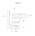
Fig. 11 is an enlarged sectional view of a portion ofFig. 10 where there is the displacement sensor. -
Fig. 12(a) is an enlarged sectional view of a portion ofFig. 3 where there is a planetary roller; andFig. 12(b) is an enlarged sectional view of a planetary roller which differs from the planetary roller shown inFig. 12(a) in that circumferential grooves are formed instead of a helical groove. -
Fig. 1 shows an electric brake system 1 embodying the present invention. This electric brake system 1 includes acaliper body 6 having opposedpieces 3 and 4 facing each other on the opposite sides of abrake disk 2 rotatable together with a wheel, and connected together by abridge 5, an electriclinear motion actuator 7 mounted in theopposed piece 3, and a pair of right and leftfriction pads - The
friction pad 8 is disposed between theopposed piece 3 and thebrake disk 2 and is supported by pad pins (not shown) mounted to thecaliper body 6 so as to be movable in the axial direction of thebrake disk 2. Theother friction pad 9 is mounted to the other opposed piece 4, which is provided on the other side of thedisk 2. Thecaliper body 6 is supported by slide pins P (seeFig. 2 ) so as to be slidable in the axial direction of thebrake disk 2. - As shown in
Fig. 1 , the electriclinear motion actuator 7 includes arotary shaft 11 driven by anelectric motor 10, a plurality ofplanetary rollers 12, anouter ring member 13 surrounding theplanetary rollers 12, acarrier 14 supporting theplanetary rollers 12, and a reactionforce receiving member 15 provided axially rearwardly of theouter ring member 13. - The
rotary shaft 11 and theelectric motor 10 are arranged parallel to each other. As shown inFig. 2 , therotary shaft 11 has agear 16 fixed thereto and meshing with agear 18 fixed to theoutput shaft 17 of theelectric motor 10 through anintermediate gear 19. The rotation of theoutput shaft 17 of theelectric motor 10 is thus transmitted to therotary shaft 11 through thegear 18, theintermediate gear 19 and then thegear 16. As shown inFig. 1 , thegear 16,intermediate gear 19 andgear 18 are covered by alid 20 mounted to theopposed piece 3. - As shown in
Fig. 3 , theplanetary rollers 12 are mounted between the radially inner surface of theouter ring member 13 and the radially outer surface of therotary shaft 11. Theplanetary rollers 12 are in rolling contact with the radially outer surface of therotary shaft 11 such that theplanetary rollers 12 rotate when therotary shaft 11 rotates due to the friction between the respectiveplanetary rollers 12 and therotary shaft 11. As shown inFig. 4 , theplanetary rollers 12 are circumferentially equidistantly spaced apart from each other. - As shown in
Fig. 3 , theplanetary rollers 12 are supported by thecarrier 14 so as to be rotatable about their respective axes and also around therotary shaft 11. Thecarrier 14 includes carrier pins 14A rotatably supporting the respectiveplanetary rollers 12, anannular carrier plate 14C, retaining the axial front ends of the carrier pins 14A so as to be circumferentially equidistantly spaced apart from each other, and anannular carrier body 14B retaining the axial rear ends of the carrier pins 14A so as to be circumferentially equidistantly spaced apart from each other. Thecarrier plate 14C and thecarrier body 14B are axially opposed to each other with theplanetary rollers 12 disposed therebetween, and are coupled together by means ofcoupling rods 21 extending between the respective circumferentially adjacent pairs ofplanetary rollers 12. Thecarrier body 14B is supported on therotary shaft 11 through aslide bearing 22 so as to be rotatable relative to therotary shaft 11. - Two radial compression ring springs 23 are wrapped around the circumferentially spaced apart carrier pins 14A, thereby radially inwardly biasing the carrier pins 14A. Under the biasing force of the radial compression ring springs 23, the radially outer surfaces of the
planetary rollers 12 are pressed against the radially outer surface of therotary shaft 11. The ring springs 23 thus prevent slippage between therotary shaft 11 and theplanetary rollers 12. In order to distribute the biasing force of the radial compression ring springs 23 over the entire axial length of eachplanetary roller 12, the two radial compression ring springs 23 are respectively provided at both ends of the carrier pins 14A. - The
outer ring member 13 is received in a receivinghole 24 formed in theopposed piece 3 of thecaliper body 6 so as to be axially slidable in the receivinghole 24. Thefriction pad 8 is located at the axial front end of theouter ring member 13, and is formed with an engagingprotrusion 25 on the back surface thereof. The engagingprotrusion 25 is engaged in engagingrecesses 26 formed in the axial front end of theouter ring member 13, thus rotationally fixing theouter ring member 13. Thus, theouter ring member 13 is rotationally fixed but axially slidable relative to thecaliper body 6. - The
outer ring member 13 has an axial front opening closed by aseal member 27. Theseal member 27 is formed by pressing a metal sheet, and fixed in position by being inserted into theouter ring member 13 with an interference fit. - A
helical rib 28 is formed on the radially inner surface of theouter ring member 13 which is engaged in ahelical groove 29 formed in the radially outer surface of eachplanetary roller 12. Thehelical rib 28 has a lead angle different from the lead angle of thehelical grooves 29 such that when theplanetary rollers 12 rotate, theouter ring member 13 is moved axially with thehelical rib 28 guided by thehelical grooves 29. Instead of thehelical groove 29 of this embodiment, which is shown inFig. 12(a) , a plurality ofcircumferential grooves 41, i.e. grooves having a lead angle of zero degrees, may be formed on the radially outer surface of eachplanetary roller 12 as shown inFig. 12(b) . With this arrangement too, when theplanetary rollers 12 rotate, theouter ring member 13 is moved axially with thehelical rib 28 guided by thecircumferential grooves 41. - A
circumferential groove 30 is formed in the inner wall of the receivinghole 24 at its portion axially rearwardly of the portion of the inner wall of thehole 24 along which theouter ring member 13 slides. Asnap ring 31 is fitted in thecircumferential groove 30. Thesnap ring 31 is formed by assembling together a plurality of circular arc-shaped split members. Anannular retainer 32 prevents radial movement of thesnap ring 31, thus retaining thesnap ring 31 in thecircumferential groove 30. - The reaction
force receiving member 15 is a ring-shaped member through which therotary shaft 11 extends. Thesnap ring 31 engages the outer edge of the reactionforce receiving member 15, thus restraining axially rearward movement of the reactionforce receiving member 15. The reactionforce receiving member 15 in turn supports thecarrier body 14B through athrust bearing 33 and aspacer 34, thereby restraining axially rearward movement of thecarrier 14. Thethrust bearing 33, which is mounted between the reactionforce receiving member 15 and thecarrier 14, prevents the rotation of thecarrier 14 from being transmitted to the reactionforce receiving member 15. - A
snap ring 35 is fitted on therotary shaft 11 at its axially front end to restrain axially forward movement of thecarrier 14. Thus, thecarrier 14 can move neither axially forwardly nor axially rearwardly. Theplanetary rollers 12, which are carried by thecarrier 14, can similarly move neither axially forwardly nor axially rearwardly. -
Thrust bearings 36 are mounted between the respectiveplanetary rollers 12 and thecarrier body 14B. Thethrust bearings 36 prevent the rotation of theplanetary rollers 12 about their respective axes from being transmitted to thecarrier body 14B while theouter ring member 13 is pressing thefriction pad 8. But the axially rearward reaction force transmitted from theouter ring member 13 to theplanetary rollers 12 while theouter ring member 13 is pressing thefriction pad 8 is transmitted to thecarrier body 14B through thethrust bearings 36. The reaction force transmitted to thecarrier 14 is then transmitted to the reactionforce receiving member 15 through thespacer 34 and thethrust bearing 33, and received by the reactionforce receiving member 15. - A ring-shaped
sensor mounting plate 37 through which therotary shaft 11 extends is fixedly positioned axially rearwardly of the reactionforce receiving member 15. Thesensor mounting plate 37 is fixed in this position by e.g. being sandwiched between theopposed piece 3 and thelid 20. Adisplacement sensor 38 is mounted on thesensor mounting plate 37 such that thesensor 38 can measure axial displacement of the radiallyinnermost portion 15a of the reactionforce receiving member 15. Thedisplacement sensor 38 may be an optical sensor, a magnetic sensor, an eddy current sensor, an electrical capacitance sensor, etc. The radiallyinnermost portion 15a of the reactionforce receiving member 15 is cylindrical in shape and rotatably supports therotary shaft 11 through rollingbearings 39 fitted in the cylindrical radiallyinnermost portion 15a. - Now the operation of the electric brake system 1 is described.
- When the
electric motor 10 is activated, therotary shaft 11 is rotated, so that theplanetary rollers 12 rotate about the respective carrier pins 14A while revolving around therotary shaft 11. This causes theouter ring member 13 and theplanetary rollers 12 to axially move relative to each other because thehelical rib 28 is engaged in thehelical grooves 29. But actually, since thecarrier 14 and thus theplanetary rollers 12 are restrained from axial movement, only theouter ring member 13 is axially moved with theplanetary rollers 12 not moving axially. Thus, the electric brake system 1 generates a braking force by converting the rotation of therotary shaft 11 produced by theelectric motor 10 to axial movement of theouter ring member 13, thereby pressing thefriction pad 8 against thebrake disk 2 with theouter ring member 13. - When the
outer ring member 13 presses thefriction pad 8, an axially rearward reaction force acts on theouter ring member 13. This reaction force is transmitted to the reactionforce receiving member 15 through theplanetary rollers 12, thethrust bearings 36, thespacer 34 and thethrust bearing 33, and received by themember 15. The reaction force causes axial deformation of the reactionforce receiving member 15. Thedisplacement sensor 38 measures the axial displacement of the reactionforce receiving member 15 due to its axial deformation. The axial displacement of themember 15 corresponds to the pressing force with which thefriction pad 8 is pressed against the brake disk. Thus, it is possible to calculate the braking force generated by the electric brake system 1 based on the output signal of thedisplacement sensor 38. This in turn makes it possible to control the braking force of the electric brake system 1 using the output signal of thedisplacement sensor 38. - When the
friction pad 8 is pressed against thebrake disk 2, frictional heat is generated between thefriction pad 8 and thebrake disk 2. Thefriction pad 8 and its surrounding area are heated to high temperature by such frictional heat. Thus, if a sensor for detecting the pressing force of thefriction pad 8 is provided on or in thebridge 5 of thecaliper body 6 or on or in the linear motion member (i.e. the outer ring member 13) of the electriclinear motion actuator 7, it is impossible to provide a circuit for processing the sensor signal sufficiently close to the (strain) sensor because the sensor is heated to high temperature. This results in increased noise in the sensor signal. - With the arrangement of the present invention, since the
displacement sensor 38 for detecting the pressing force of thefriction pad 8 is provided, not in or on the linear motion member (outer ring member 13) of the electriclinear motion actuator 7, but at a portion for receiving a reaction force applied to the linear motion member (i.e. near the reaction force receiving member 15). Thedisplacement sensor 38 is thus sufficiently spaced apart from thefriction pad 8, so that thesensor 38 and its surrounding area are less likely to be heated to high temperature. This makes it possible to detect the pressing force of thefriction pad 8 with high accuracy. - With this electric brake system 1, since the
thrust bearing 33 prevents transmission of rotation of thecarrier 14 to the reactionforce receiving member 15, while allowing only transmission of thrust loads to the reactionforce receiving member 15, the reactionforce receiving member 15 is displaced in a stable manner. This makes it possible to detect the pressing force of thefriction pad 8 with high accuracy. - When the reaction force applied to the
outer ring member 13 is received by the reactionforce receiving member 15, the reactionforce receiving member 15 is more markedly deformed at its radially inner portion than at its radially outer portion. Thus, by placing thedisplacement sensor 38 such that thesensor 38 can measure the axial displacement of, not the radially outer portion of the reactionforce receiving member 15, but the radiallyinnermost portion 15a of the reactionforce receiving member 15, as shown in the above embodiment, it is possible to detect the pressing force of thefriction pad 8 with higher accuracy. Thedisplacement sensor 38 may be mounted on a radially extending strip plate member, but is preferably mounted on the ring-shapedsensor mounting plate 37 as shown in the embodiment, because the ring-shapedsensor mounting plate 37 is higher in rigidity and thus can minimize vibration of thedisplacement sensor 38, which stabilizes detection accuracy of thedisplacement sensor 38. - If an optical sensor is used as the
displacement sensor 38, the space between thedisplacement sensor 38 and the reactionforce receiving member 15 is preferably covered with a soft member (not shown) which can be deformed as the reactionforce receiving member 15 is displaced. Such a soft member keeps dust, lubricating oil, etc. away from the sensing area of the optical sensor, allowing thedisplacement sensor 38 to maintain high detection accuracy for a prolonged period of time. - In the embodiment, the
snap ring 31 directly restrains movement of the reactionforce receiving member 15. But instead, as shown inFig. 5 , anelastic member 40 may be placed between thesnap ring 31 and the reactionforce receiving member 15 so that thesnap ring 31 indirectly restrains movement of the reactionforce receiving member 15 through theelastic member 40. With the latter arrangement, when the reactionforce receiving member 15 receives the axially rearward reaction force applied to theouter ring member 13, the reactionforce receiving member 15 is displaced not only due to strain of the reactionforce receiving member 15 itself, but also due to the deformation of theelastic member 40. Thus, by providing theelastic member 40, it is possible to displace the reactionforce receiving member 15 more markedly than when the reactionforce receiving member 15 is directly supported by thesnap ring 31. This in turn makes it possible to detect the pressing force of thefriction pad 8 with higher resolution. - The
elastic member 40 may be a coil spring, but is preferably, as shown, an annular metal member having an L-shaped section and kept in abutment with the reactionforce receiving member 15 at its portion located radially inwardly of the radially inner periphery of thesnap ring 31. Such an L-shaped metal elastic member can support high axial loads even though its axial length is small. Thus by using such an elastic member, it is possible to minimize the axial length of the electric brake system and thus its installation space. - In the above embodiment, as the linear motion mechanism for converting the rotary motion of the
rotary shaft 11 to the linear motion of the linear motion member, a planetary roller mechanism is used, including a plurality ofplanetary rollers 12 which are in rolling contact with the radially outer surface of therotary shaft 11, acarrier 14 retaining theplanetary rollers 12 so as to be rotatable about their own axes and revolve around the rotary shaft, thecarrier 14 being restrained from axial movement, and anouter ring member 13 surrounding theplanetary rollers 12, as the linear motion member, wherein ahelical rib 28 is formed on the radially inner surface of theouter ring member 13 which is engaged inhelical grooves 29 orcircumferential grooves 41 formed in the radially outer surfaces of theplanetary rollers 12. But the present invention is applicable to an electric brake system using a different linear motion mechanism. - By way of example,
Fig. 6 shows an electric brake system including a ball-screw mechanism as the linear motion mechanism. In the following description, elements corresponding to those of the above embodiment are denoted by identical numerals and their description is omitted. - In
Fig. 6 , the electric linear motion actuator includes arotary shaft 11, a threadedshaft 50 integral with therotary shaft 11, anut 51 surrounding the threadedshaft 50, a plurality ofballs 54 mounted between athread groove 52 formed in the outer periphery of the threadedshaft 50 and athread groove 53 formed in the inner periphery of thenut 51, a return tube, not shown, through which theballs 54 are returned from the terminal point to the starting point, of thethread groove 53 of thenut 51, and a reactionforce receiving member 15 provided axially rearwardly of thenut 51. - The
nut 51 is received in a receivinghole 24 formed in theopposed piece 3 of thecaliper body 6 so as to be rotationally fixed but axially slidable relative to thecaliper body 6. Aspacer 34 is provided at the axially rear end of the threadedshaft 50 so as to rotate in unison with the threadedshaft 50. Thespacer 34 is supported by the reactionforce receiving member 15 through athrust bearing 33. The reactionforce receiving member 15 axially supports thenut 51 through thespacer 34, thethrust bearing 33 and the threadedshaft 50, thereby restraining axially rearward movement of thenut 51. - With this electric linear motion actuator, the
nut 51 is moved axially forward by rotating therotary shaft 11, thus rotating the threadedshaft 50 and thenut 51 relative to each other. When thenut 51 is moved axially forward, an axially rearward reaction force is applied to the threadedshaft 50. This reaction force is transmitted to the reactionforce receiving member 15 through thespacer 34 and thethrust bearing 33 and received by the reactionforce receiving member 15. Under this reaction force, the reactionforce receiving member 15 is axially displaced, and the axial displacement of themember 15 is measured by thedisplacement sensor 38. Thus, based on the output signal of thedisplacement sensor 38, it is possible to detect the pressing force of thefriction pad 8. -
Fig. 7 shows an electric brake system including a ball-ramp mechanism as the linear motion mechanism. - In
Fig. 7 , the electric linear motion actuator includes arotary shaft 11, arotary disk 60 rotationally fixed to the outer periphery of the rotary shaft, alinear motion disk 61 located axially forwardly of, and axially facing, therotary disk 60, a plurality ofballs 62 disposed between therotary disk 60 and thelinear motion disk 61, and a reactionforce receiving member 15 positioned axially rearwardly of thelinear motion disk 61. - The
linear motion disk 61 is received in a receivinghole 24 formed in theopposed piece 3 of thecaliper body 6 so as to be rotationally fixed but axially slidable relative to thecaliper body 6. Aspacer 34 is provided at the axially rear end of therotary disk 60 so as to be rotatable in unison with therotary disk 60. Thespacer 34 is supported by the reactionforce receiving member 15 through athrust bearing 33. The reactionforce receiving member 15 axially supports therotary disk 60 through thespacer 34 and thethrust bearing 33, thus restraining axially rearward movement of therotary disk 60. - As shown in
Figs. 7 and8 , thesurface 60a of therotary disk 60 facing thelinear motion disk 61 is formed withinclined grooves 63 of which the depth gradually decreases in one circumferential direction, while thesurface 61a of thelinear motion disk 61 facing therotary disk 60 is formed withinclined grooves 64 of which the depth gradually decreases in the opposite circumferential direction. As shown inFig. 9(a) , theballs 62 are received between the respectiveinclined grooves 63 of therotary disk 60 and the correspondinginclined grooves 64 of thelinear motion disk 61. As shown inFig. 9(b) , when therotary disk 60 rotates relative to thelinear motion disk 61, theballs 62 roll in the respective pairs ofinclined grooves rotary disk 60 and thelinear motion disk 61 increases. - With this electric linear motion actuator, when the
rotary shaft 11 is rotated, thelinear motion disk 61 and therotary disk 60 rotate relative to each other such that thelinear motion disk 61 is moved axially forwardly. When thedisk 61 is moved forwardly, an axially rearward reaction force acts on therotary disk 60. This reaction force is transmitted to the reactionforce receiving member 15 through thespacer 34 and thethrust bearing 33, and received by the reactionforce receiving member 15. Under this reaction force, the reactionforce receiving member 15 is deformed in the axial direction. Thedisplacement sensor 38 measures the axial displacement of the reactionforce receiving member 15 due to the axial deformation of themember 15. Thus, it is possible to detect the pressing force of thefriction pad 8 based on the output signal of thedisplacement sensor 38. - If a magnetic sensor is used as the
displacement sensor 38, as shown inFigs. 10 and11 , twopermanent magnets 70 may be fixed to the reactionforce receiving member 15 which are magnetized in the direction perpendicular to the axial direction such that the north and south poles of one of themagnets 70 axially face the south and north poles of theother magnet 70, respectively, and positioned such that thedisplacement sensor 38 is located in the vicinity of the boundary between the axially adjacent north and south poles of therespective magnets 70. With this arrangement, the output signal of thedisplacement sensor 38 changes sharply only when the reactionforce receiving member 60 is displaced in the axial direction, and scarcely changes for displacement of the reaction force receiving member in a direction other than the axial direction. Thus, it is possible to detect the pressing force of thefriction pad 8 with high accuracy in a stable manner, practically without the influence of external vibrations. - As shown in
Fig. 11 , thepermanent magnets 70 are fixed on the radiallyouter surface 72 of atubular portion 71 axially rearwardly extending from the radially inner portion of the reactionforce receiving member 15, which is an annular plate member. Thesensor mounting plate 37 has a radiallyinner surface 73 radially facing the radiallyouter surface 72 of thetubular portion 71. Thedisplacement sensor 38 is fixed on this radiallyinner surface 73. -
- 1. Electric brake system
- 2. Brake disk
- 6. Caliper body
- 8. Friction pad
- 10. Electric motor
- 11. Rotary shaft
- 12. Planetary roller
- 13. Outer ring member
- 14. Carrier
- 15. Reaction force receiving member
- 15a. Radially innermost portion
- 24. Receiving hole
- 28. Helical rib
- 29. Helical groove
- 30. Circumferential groove
- 31. Snap ring
- 33. Thrust bearing
- 37. Sensor mounting plate
- 38. Displacement sensor
- 40. Elastic member
- 41. Circumferential groove
- 70. Permanent magnet
Claims (11)
- An electric brake system comprising a rotary shaft (11) driven by an electric motor (10), a linear motion member, a linear motion mechanism for converting a rotary motion of the rotary shaft (11) to a linear motion of the linear motion member, a caliper body (6) formed with a receiving hole (24) in which the linear motion member is axially slidably received, and a friction pad (8) arranged at an axial front end of the linear motion member, wherein the linear motion member is configured to press the friction pad (8) against a brake disk (2),
characterized in that the electric brake system further comprises a reaction force receiving member (15) provided axially rearwardly of the linear motion member for receiving an axially rearward reaction force applied to the linear motion member when the friction pad (8) is pressed by the linear motion member, and a displacement sensor (38) for measuring a displacement of the reaction force receiving member (15). - The electric brake system of claim 1, further comprising a snap ring (31) fitted in a circumferential groove (30) formed in an inner wall of the receiving hole (24) at a portion of the inner wall located axially rearwardly of an area of the inner wall where the linear motion member slides, the snap ring (31) restraining axially rearward movement of the reaction force receiving member (15).
- The electric brake system of claim 2, further comprising an elastic member (40) disposed between the snap ring (31) and the reaction force receiving member (15).
- The electric brake system of claim 3, wherein the elastic member (40) comprises an annular metal member having an L-shaped section and having a portion located radially inwardly of a radially inner periphery of the snap ring (31) and in abutment with the reaction force receiving member (15).
- The electric brake system of any of claims 1 to 4, wherein the reaction force receiving member (15) has a radially innermost portion (15a), and wherein the displacement sensor (38) is mounted such that the displacement sensor (38) can measure an axial displacement of the radially innermost portion (15a).
- The electric brake system of any of claims 1 to 5, further comprising a ring-shaped sensor mounting plate (37) fixedly positioned axially rearwardly of the reaction force receiving member (15) such that the rotary shaft (11) extends through the sensor mounting plate (37), wherein the displacement sensor (38) is mounted on the sensor mounting plate (37).
- The electric brake system of any of claims 1 to 6, wherein the displacement sensor (38) comprises an optical sensor.
- The electric brake system of claim 7, further comprising a soft member covering a space between the optical sensor and the reaction force receiving member (15), the soft member being deformable as the reaction force receiving member (15) is displaced.
- The electric brake system of any of claims 1 to 6, wherein the displacement sensor (38) comprises one of a magnetic sensor, an eddy current sensor and an electrical capacitance sensor.
- The electric brake system of any of claims 1 to 6, further comprising at least two permanent magnets (70) magnetized in a direction perpendicular to the axial direction, and fixed to the reaction force receiving member (15) such that the north pole and the south pole of the respective permanent magnets are located axially adjacent to each other, wherein the displacement sensor (38) comprises a magnetic sensor located in a vicinity of a boundary between said axially adjacent north pole and south pole.
- The electric brake system of any of claims 1 to 10, wherein the linear motion mechanism comprises a plurality of planetary rollers (12) kept in rolling contact with a radially outer surface of the rotary shaft (11), a carrier (14) retaining the planetary rollers (12) such that the planetary rollers (12) can rotate about axes of the respective planetary rollers (12) and can revolve around the rotary shaft, the carrier (14) being restrained from axial movement, and an outer ring member (13) surrounding the planetary rollers (12) and constituting the linear motion member, wherein the outer ring member (13) has a helical rib (28) formed on a radially inner surface of the outer ring member (13), wherein each of the planetary rollers (12) have a helical groove (29) or circumferential grooves (41) formed in a radially outer surface of the planetary roller (12), and wherein the helical rib (28) is engaged in the helical grooves (29) or the circumferential grooves (41).
Applications Claiming Priority (3)
| Application Number | Priority Date | Filing Date | Title |
|---|---|---|---|
| JP2011001596 | 2011-01-07 | ||
| JP2011186954A JP5795908B2 (en) | 2011-01-07 | 2011-08-30 | Electric brake device |
| PCT/JP2011/079004 WO2012093568A1 (en) | 2011-01-07 | 2011-12-15 | Electric brake device |
Publications (3)
| Publication Number | Publication Date |
|---|---|
| EP2662587A1 true EP2662587A1 (en) | 2013-11-13 |
| EP2662587A4 EP2662587A4 (en) | 2018-05-02 |
| EP2662587B1 EP2662587B1 (en) | 2019-10-30 |
Family
ID=46457428
Family Applications (1)
| Application Number | Title | Priority Date | Filing Date |
|---|---|---|---|
| EP11855063.1A Active EP2662587B1 (en) | 2011-01-07 | 2011-12-15 | Electric brake device |
Country Status (5)
| Country | Link |
|---|---|
| US (1) | US9217479B2 (en) |
| EP (1) | EP2662587B1 (en) |
| JP (1) | JP5795908B2 (en) |
| CN (1) | CN103314234B (en) |
| WO (1) | WO2012093568A1 (en) |
Cited By (2)
| Publication number | Priority date | Publication date | Assignee | Title |
|---|---|---|---|---|
| EP2733379A1 (en) * | 2011-07-13 | 2014-05-21 | NTN Corporation | Electric brake device |
| EP3124346A4 (en) * | 2014-03-24 | 2017-12-06 | NTN Corporation | Electric brake device and electric brake device system |
Families Citing this family (10)
| Publication number | Priority date | Publication date | Assignee | Title |
|---|---|---|---|---|
| JP6300635B2 (en) | 2014-05-21 | 2018-03-28 | Ntn株式会社 | Electric brake device |
| JP5876564B2 (en) * | 2014-12-24 | 2016-03-02 | Ntn株式会社 | Electric linear actuator |
| JP6414114B2 (en) * | 2016-03-24 | 2018-10-31 | トヨタ自動車株式会社 | Electric brake caliper |
| ES2850203T3 (en) * | 2017-06-08 | 2021-08-26 | Ims Gear Se & Co Kgaa | Planetary wheel gear arrangement, in particular for an electromechanical service brake or an electromechanical parking brake for a motor vehicle |
| JP2020099149A (en) * | 2018-12-19 | 2020-06-25 | 東京パーツ工業株式会社 | Brushless motor |
| US11193546B2 (en) * | 2019-02-11 | 2021-12-07 | Schaeffler Technologies AG & Co. KG | Ball-ramp clutch actuator assembly |
| EP3938672A1 (en) * | 2019-03-13 | 2022-01-19 | Linak A/S | Linear actuator |
| DE102019106572B4 (en) * | 2019-03-14 | 2022-08-04 | Auma Riester Gmbh & Co. Kg | Force measuring device, gear and actuator and use of a force measuring device |
| DE102021101088A1 (en) * | 2020-01-22 | 2021-07-22 | Mando Corporation | Friction braking system for a vehicle |
| JP2024042303A (en) | 2022-09-15 | 2024-03-28 | ナブテスコ株式会社 | Vehicle braking device |
Family Cites Families (24)
| Publication number | Priority date | Publication date | Assignee | Title |
|---|---|---|---|---|
| SE460783B (en) * | 1988-03-21 | 1989-11-20 | Sab Nife Ab | actuator |
| AU1961397A (en) * | 1996-02-15 | 1997-09-02 | Kelsey-Hayes Company | Electrical disc brake actuation mechanism |
| US6412610B1 (en) * | 1999-11-24 | 2002-07-02 | Delphi Technologies, Inc. | Electric brake caliper |
| SE524118C2 (en) | 2001-05-30 | 2004-06-29 | Haldex Brake Prod Ab | Device in a vehicle brake arrangement |
| JP4446111B2 (en) | 2001-06-29 | 2010-04-07 | 日立オートモティブシステムズ株式会社 | Electric brake device |
| JP4304418B2 (en) * | 2002-02-28 | 2009-07-29 | 株式会社日立製作所 | Electric disc brake |
| JP3880427B2 (en) | 2002-03-29 | 2007-02-14 | 日信工業株式会社 | Electric disc brake |
| ITTO20021104A1 (en) * | 2002-12-20 | 2004-06-21 | Skf Ind Spa | ELECTROMECHANICAL SCREW ACTUATOR GROUP |
| JP4170089B2 (en) | 2002-12-26 | 2008-10-22 | 日信工業株式会社 | Electric disc brake |
| JP4933778B2 (en) * | 2003-05-07 | 2012-05-16 | ローベルト ボツシユ ゲゼルシヤフト ミツト ベシユレンクテル ハフツング | Force measuring element |
| WO2004099746A1 (en) * | 2003-05-07 | 2004-11-18 | Robert Bosch Gmbh | Force-sensing element |
| DE102005015726B4 (en) * | 2005-04-06 | 2019-03-14 | Robert Bosch Gmbh | Automotive parking brake with position sensor |
| DE102005055084B4 (en) * | 2005-09-29 | 2017-02-09 | Robert Bosch Gmbh | Combined service and parking brake device |
| DE102005055085B4 (en) * | 2005-09-29 | 2020-09-24 | Robert Bosch Gmbh | Combined service and parking brake device as well as a method for performing emergency braking |
| JP4834397B2 (en) * | 2005-12-15 | 2011-12-14 | 日立オートモティブシステムズ株式会社 | Brake control device for vehicle |
| DE102006018952A1 (en) * | 2006-04-24 | 2007-10-25 | Robert Bosch Gmbh | Disc brake for vehicle, comprises brake disk and brake pad which is designed against brake disk to provide braking action and force sensor is arranged at side of brake pads |
| US7565953B2 (en) * | 2006-05-11 | 2009-07-28 | Meggitt Aircraft Braking Systems | Brake force transducer for electric brakes |
| JP4803372B2 (en) | 2006-06-30 | 2011-10-26 | 日立オートモティブシステムズ株式会社 | Electric brake device and control device for electric brake device |
| JP2008312436A (en) * | 2007-05-15 | 2008-12-25 | Ntn Corp | Electric direct acting actuator and electric braking device |
| JP5376279B2 (en) * | 2008-02-20 | 2013-12-25 | Ntn株式会社 | Electric linear actuator and electric brake device |
| JP5282998B2 (en) * | 2008-10-07 | 2013-09-04 | Ntn株式会社 | Electric linear actuator and electric brake device |
| JP2010270788A (en) * | 2009-05-19 | 2010-12-02 | Akebono Brake Ind Co Ltd | Disc brake |
| JP5676382B2 (en) * | 2011-07-13 | 2015-02-25 | Ntn株式会社 | Electric brake device |
| JP5977016B2 (en) * | 2011-10-26 | 2016-08-24 | Ntn株式会社 | Electric linear actuator and electric brake device |
-
2011
- 2011-08-30 JP JP2011186954A patent/JP5795908B2/en active Active
- 2011-12-15 WO PCT/JP2011/079004 patent/WO2012093568A1/en active Application Filing
- 2011-12-15 EP EP11855063.1A patent/EP2662587B1/en active Active
- 2011-12-15 CN CN201180064273.7A patent/CN103314234B/en active Active
- 2011-12-15 US US13/978,450 patent/US9217479B2/en not_active Expired - Fee Related
Non-Patent Citations (1)
| Title |
|---|
| See references of WO2012093568A1 * |
Cited By (6)
| Publication number | Priority date | Publication date | Assignee | Title |
|---|---|---|---|---|
| EP2733379A1 (en) * | 2011-07-13 | 2014-05-21 | NTN Corporation | Electric brake device |
| EP2733379A4 (en) * | 2011-07-13 | 2014-12-03 | Ntn Toyo Bearing Co Ltd | Electric brake device |
| US9475469B2 (en) | 2011-07-13 | 2016-10-25 | Ntn Corporation | Electric brake system |
| US10605319B2 (en) | 2011-07-13 | 2020-03-31 | Ntn Corporation | Electric linear motion actuator |
| EP3124346A4 (en) * | 2014-03-24 | 2017-12-06 | NTN Corporation | Electric brake device and electric brake device system |
| US10125834B2 (en) | 2014-03-24 | 2018-11-13 | Ntn Corporation | Electric brake device and electric brake device system |
Also Published As
| Publication number | Publication date |
|---|---|
| CN103314234A (en) | 2013-09-18 |
| JP2012154482A (en) | 2012-08-16 |
| WO2012093568A1 (en) | 2012-07-12 |
| CN103314234B (en) | 2016-03-09 |
| EP2662587B1 (en) | 2019-10-30 |
| US9217479B2 (en) | 2015-12-22 |
| EP2662587A4 (en) | 2018-05-02 |
| JP5795908B2 (en) | 2015-10-14 |
| US20130327601A1 (en) | 2013-12-12 |
Similar Documents
| Publication | Publication Date | Title |
|---|---|---|
| EP2662587B1 (en) | Electric brake device | |
| US10605319B2 (en) | Electric linear motion actuator | |
| JP5778513B2 (en) | Magnetic load sensor and linear actuator for linear actuator | |
| EP2767812B1 (en) | Magnetic load sensor for use in a linear motion actuator and linear motion actuator | |
| EP2873957B1 (en) | Magnetic load sensor and electric brake device | |
| EP2772659B1 (en) | Electric direct-acting actuator and electric brake apparatus | |
| EP2775170B1 (en) | Electric linear motion actuator | |
| EP2944936B1 (en) | Magnetic load sensor and electric brake device | |
| JP6505399B2 (en) | Load sensor for vehicle brake device, electric linear actuator and electric brake device | |
| JP5876564B2 (en) | Electric linear actuator | |
| JP2013257000A (en) | Magnetic load sensor and electrically-operated brake system |
Legal Events
| Date | Code | Title | Description |
|---|---|---|---|
| PUAI | Public reference made under article 153(3) epc to a published international application that has entered the european phase |
Free format text: ORIGINAL CODE: 0009012 |
|
| 17P | Request for examination filed |
Effective date: 20130807 |
|
| AK | Designated contracting states |
Kind code of ref document: A1 Designated state(s): AL AT BE BG CH CY CZ DE DK EE ES FI FR GB GR HR HU IE IS IT LI LT LU LV MC MK MT NL NO PL PT RO RS SE SI SK SM TR |
|
| DAX | Request for extension of the european patent (deleted) | ||
| RA4 | Supplementary search report drawn up and despatched (corrected) |
Effective date: 20180403 |
|
| RIC1 | Information provided on ipc code assigned before grant |
Ipc: F16D 66/00 20060101ALI20180326BHEP Ipc: F16D 65/18 20060101AFI20180326BHEP Ipc: F16D 65/14 20060101ALI20180326BHEP |
|
| GRAP | Despatch of communication of intention to grant a patent |
Free format text: ORIGINAL CODE: EPIDOSNIGR1 |
|
| STAA | Information on the status of an ep patent application or granted ep patent |
Free format text: STATUS: GRANT OF PATENT IS INTENDED |
|
| INTG | Intention to grant announced |
Effective date: 20190606 |
|
| GRAS | Grant fee paid |
Free format text: ORIGINAL CODE: EPIDOSNIGR3 |
|
| GRAA | (expected) grant |
Free format text: ORIGINAL CODE: 0009210 |
|
| STAA | Information on the status of an ep patent application or granted ep patent |
Free format text: STATUS: THE PATENT HAS BEEN GRANTED |
|
| AK | Designated contracting states |
Kind code of ref document: B1 Designated state(s): AL AT BE BG CH CY CZ DE DK EE ES FI FR GB GR HR HU IE IS IT LI LT LU LV MC MK MT NL NO PL PT RO RS SE SI SK SM TR |
|
| REG | Reference to a national code |
Ref country code: GB Ref legal event code: FG4D |
|
| REG | Reference to a national code |
Ref country code: CH Ref legal event code: EP |
|
| REG | Reference to a national code |
Ref country code: AT Ref legal event code: REF Ref document number: 1196470 Country of ref document: AT Kind code of ref document: T Effective date: 20191115 |
|
| REG | Reference to a national code |
Ref country code: DE Ref legal event code: R096 Ref document number: 602011063114 Country of ref document: DE |
|
| REG | Reference to a national code |
Ref country code: IE Ref legal event code: FG4D |
|
| REG | Reference to a national code |
Ref country code: LT Ref legal event code: MG4D |
|
| PG25 | Lapsed in a contracting state [announced via postgrant information from national office to epo] |
Ref country code: PL Free format text: LAPSE BECAUSE OF FAILURE TO SUBMIT A TRANSLATION OF THE DESCRIPTION OR TO PAY THE FEE WITHIN THE PRESCRIBED TIME-LIMIT Effective date: 20191030 Ref country code: NO Free format text: LAPSE BECAUSE OF FAILURE TO SUBMIT A TRANSLATION OF THE DESCRIPTION OR TO PAY THE FEE WITHIN THE PRESCRIBED TIME-LIMIT Effective date: 20200130 Ref country code: LT Free format text: LAPSE BECAUSE OF FAILURE TO SUBMIT A TRANSLATION OF THE DESCRIPTION OR TO PAY THE FEE WITHIN THE PRESCRIBED TIME-LIMIT Effective date: 20191030 Ref country code: NL Free format text: LAPSE BECAUSE OF FAILURE TO SUBMIT A TRANSLATION OF THE DESCRIPTION OR TO PAY THE FEE WITHIN THE PRESCRIBED TIME-LIMIT Effective date: 20191030 Ref country code: BG Free format text: LAPSE BECAUSE OF FAILURE TO SUBMIT A TRANSLATION OF THE DESCRIPTION OR TO PAY THE FEE WITHIN THE PRESCRIBED TIME-LIMIT Effective date: 20200130 Ref country code: SE Free format text: LAPSE BECAUSE OF FAILURE TO SUBMIT A TRANSLATION OF THE DESCRIPTION OR TO PAY THE FEE WITHIN THE PRESCRIBED TIME-LIMIT Effective date: 20191030 Ref country code: LV Free format text: LAPSE BECAUSE OF FAILURE TO SUBMIT A TRANSLATION OF THE DESCRIPTION OR TO PAY THE FEE WITHIN THE PRESCRIBED TIME-LIMIT Effective date: 20191030 Ref country code: ES Free format text: LAPSE BECAUSE OF FAILURE TO SUBMIT A TRANSLATION OF THE DESCRIPTION OR TO PAY THE FEE WITHIN THE PRESCRIBED TIME-LIMIT Effective date: 20191030 Ref country code: GR Free format text: LAPSE BECAUSE OF FAILURE TO SUBMIT A TRANSLATION OF THE DESCRIPTION OR TO PAY THE FEE WITHIN THE PRESCRIBED TIME-LIMIT Effective date: 20200131 Ref country code: PT Free format text: LAPSE BECAUSE OF FAILURE TO SUBMIT A TRANSLATION OF THE DESCRIPTION OR TO PAY THE FEE WITHIN THE PRESCRIBED TIME-LIMIT Effective date: 20200302 Ref country code: FI Free format text: LAPSE BECAUSE OF FAILURE TO SUBMIT A TRANSLATION OF THE DESCRIPTION OR TO PAY THE FEE WITHIN THE PRESCRIBED TIME-LIMIT Effective date: 20191030 |
|
| REG | Reference to a national code |
Ref country code: NL Ref legal event code: MP Effective date: 20191030 |
|
| PG25 | Lapsed in a contracting state [announced via postgrant information from national office to epo] |
Ref country code: IS Free format text: LAPSE BECAUSE OF FAILURE TO SUBMIT A TRANSLATION OF THE DESCRIPTION OR TO PAY THE FEE WITHIN THE PRESCRIBED TIME-LIMIT Effective date: 20200229 Ref country code: RS Free format text: LAPSE BECAUSE OF FAILURE TO SUBMIT A TRANSLATION OF THE DESCRIPTION OR TO PAY THE FEE WITHIN THE PRESCRIBED TIME-LIMIT Effective date: 20191030 Ref country code: HR Free format text: LAPSE BECAUSE OF FAILURE TO SUBMIT A TRANSLATION OF THE DESCRIPTION OR TO PAY THE FEE WITHIN THE PRESCRIBED TIME-LIMIT Effective date: 20191030 |
|
| PG25 | Lapsed in a contracting state [announced via postgrant information from national office to epo] |
Ref country code: AL Free format text: LAPSE BECAUSE OF FAILURE TO SUBMIT A TRANSLATION OF THE DESCRIPTION OR TO PAY THE FEE WITHIN THE PRESCRIBED TIME-LIMIT Effective date: 20191030 |
|
| PG25 | Lapsed in a contracting state [announced via postgrant information from national office to epo] |
Ref country code: DK Free format text: LAPSE BECAUSE OF FAILURE TO SUBMIT A TRANSLATION OF THE DESCRIPTION OR TO PAY THE FEE WITHIN THE PRESCRIBED TIME-LIMIT Effective date: 20191030 Ref country code: EE Free format text: LAPSE BECAUSE OF FAILURE TO SUBMIT A TRANSLATION OF THE DESCRIPTION OR TO PAY THE FEE WITHIN THE PRESCRIBED TIME-LIMIT Effective date: 20191030 Ref country code: RO Free format text: LAPSE BECAUSE OF FAILURE TO SUBMIT A TRANSLATION OF THE DESCRIPTION OR TO PAY THE FEE WITHIN THE PRESCRIBED TIME-LIMIT Effective date: 20191030 Ref country code: CZ Free format text: LAPSE BECAUSE OF FAILURE TO SUBMIT A TRANSLATION OF THE DESCRIPTION OR TO PAY THE FEE WITHIN THE PRESCRIBED TIME-LIMIT Effective date: 20191030 |
|
| REG | Reference to a national code |
Ref country code: CH Ref legal event code: PL Ref country code: DE Ref legal event code: R097 Ref document number: 602011063114 Country of ref document: DE |
|
| REG | Reference to a national code |
Ref country code: AT Ref legal event code: MK05 Ref document number: 1196470 Country of ref document: AT Kind code of ref document: T Effective date: 20191030 |
|
| REG | Reference to a national code |
Ref country code: BE Ref legal event code: MM Effective date: 20191231 |
|
| PG25 | Lapsed in a contracting state [announced via postgrant information from national office to epo] |
Ref country code: MC Free format text: LAPSE BECAUSE OF FAILURE TO SUBMIT A TRANSLATION OF THE DESCRIPTION OR TO PAY THE FEE WITHIN THE PRESCRIBED TIME-LIMIT Effective date: 20191030 Ref country code: SK Free format text: LAPSE BECAUSE OF FAILURE TO SUBMIT A TRANSLATION OF THE DESCRIPTION OR TO PAY THE FEE WITHIN THE PRESCRIBED TIME-LIMIT Effective date: 20191030 Ref country code: IT Free format text: LAPSE BECAUSE OF FAILURE TO SUBMIT A TRANSLATION OF THE DESCRIPTION OR TO PAY THE FEE WITHIN THE PRESCRIBED TIME-LIMIT Effective date: 20191030 Ref country code: SM Free format text: LAPSE BECAUSE OF FAILURE TO SUBMIT A TRANSLATION OF THE DESCRIPTION OR TO PAY THE FEE WITHIN THE PRESCRIBED TIME-LIMIT Effective date: 20191030 |
|
| PLBE | No opposition filed within time limit |
Free format text: ORIGINAL CODE: 0009261 |
|
| STAA | Information on the status of an ep patent application or granted ep patent |
Free format text: STATUS: NO OPPOSITION FILED WITHIN TIME LIMIT |
|
| GBPC | Gb: european patent ceased through non-payment of renewal fee |
Effective date: 20200130 |
|
| 26N | No opposition filed |
Effective date: 20200731 |
|
| PG25 | Lapsed in a contracting state [announced via postgrant information from national office to epo] |
Ref country code: IE Free format text: LAPSE BECAUSE OF NON-PAYMENT OF DUE FEES Effective date: 20191215 Ref country code: GB Free format text: LAPSE BECAUSE OF NON-PAYMENT OF DUE FEES Effective date: 20200130 Ref country code: LU Free format text: LAPSE BECAUSE OF NON-PAYMENT OF DUE FEES Effective date: 20191215 |
|
| PG25 | Lapsed in a contracting state [announced via postgrant information from national office to epo] |
Ref country code: AT Free format text: LAPSE BECAUSE OF FAILURE TO SUBMIT A TRANSLATION OF THE DESCRIPTION OR TO PAY THE FEE WITHIN THE PRESCRIBED TIME-LIMIT Effective date: 20191030 Ref country code: CH Free format text: LAPSE BECAUSE OF NON-PAYMENT OF DUE FEES Effective date: 20191231 Ref country code: SI Free format text: LAPSE BECAUSE OF FAILURE TO SUBMIT A TRANSLATION OF THE DESCRIPTION OR TO PAY THE FEE WITHIN THE PRESCRIBED TIME-LIMIT Effective date: 20191030 Ref country code: BE Free format text: LAPSE BECAUSE OF NON-PAYMENT OF DUE FEES Effective date: 20191231 Ref country code: LI Free format text: LAPSE BECAUSE OF NON-PAYMENT OF DUE FEES Effective date: 20191231 |
|
| PG25 | Lapsed in a contracting state [announced via postgrant information from national office to epo] |
Ref country code: CY Free format text: LAPSE BECAUSE OF FAILURE TO SUBMIT A TRANSLATION OF THE DESCRIPTION OR TO PAY THE FEE WITHIN THE PRESCRIBED TIME-LIMIT Effective date: 20191030 |
|
| PG25 | Lapsed in a contracting state [announced via postgrant information from national office to epo] |
Ref country code: HU Free format text: LAPSE BECAUSE OF FAILURE TO SUBMIT A TRANSLATION OF THE DESCRIPTION OR TO PAY THE FEE WITHIN THE PRESCRIBED TIME-LIMIT; INVALID AB INITIO Effective date: 20111215 Ref country code: MT Free format text: LAPSE BECAUSE OF FAILURE TO SUBMIT A TRANSLATION OF THE DESCRIPTION OR TO PAY THE FEE WITHIN THE PRESCRIBED TIME-LIMIT Effective date: 20191030 |
|
| PG25 | Lapsed in a contracting state [announced via postgrant information from national office to epo] |
Ref country code: TR Free format text: LAPSE BECAUSE OF FAILURE TO SUBMIT A TRANSLATION OF THE DESCRIPTION OR TO PAY THE FEE WITHIN THE PRESCRIBED TIME-LIMIT Effective date: 20191030 |
|
| PG25 | Lapsed in a contracting state [announced via postgrant information from national office to epo] |
Ref country code: MK Free format text: LAPSE BECAUSE OF FAILURE TO SUBMIT A TRANSLATION OF THE DESCRIPTION OR TO PAY THE FEE WITHIN THE PRESCRIBED TIME-LIMIT Effective date: 20191030 |
|
| PGFP | Annual fee paid to national office [announced via postgrant information from national office to epo] |
Ref country code: FR Payment date: 20221110 Year of fee payment: 12 Ref country code: DE Payment date: 20221102 Year of fee payment: 12 |