EP2662553A2 - Cooling medium supply system and method - Google Patents
Cooling medium supply system and method Download PDFInfo
- Publication number
- EP2662553A2 EP2662553A2 EP13166854.3A EP13166854A EP2662553A2 EP 2662553 A2 EP2662553 A2 EP 2662553A2 EP 13166854 A EP13166854 A EP 13166854A EP 2662553 A2 EP2662553 A2 EP 2662553A2
- Authority
- EP
- European Patent Office
- Prior art keywords
- cooling medium
- supply
- gas turbine
- turbine engine
- engine
- Prior art date
- Legal status (The legal status is an assumption and is not a legal conclusion. Google has not performed a legal analysis and makes no representation as to the accuracy of the status listed.)
- Granted
Links
Images

Classifications
-
- F—MECHANICAL ENGINEERING; LIGHTING; HEATING; WEAPONS; BLASTING
- F02—COMBUSTION ENGINES; HOT-GAS OR COMBUSTION-PRODUCT ENGINE PLANTS
- F02C—GAS-TURBINE PLANTS; AIR INTAKES FOR JET-PROPULSION PLANTS; CONTROLLING FUEL SUPPLY IN AIR-BREATHING JET-PROPULSION PLANTS
- F02C7/00—Features, components parts, details or accessories, not provided for in, or of interest apart form groups F02C1/00 - F02C6/00; Air intakes for jet-propulsion plants
- F02C7/12—Cooling of plants
-
- F—MECHANICAL ENGINEERING; LIGHTING; HEATING; WEAPONS; BLASTING
- F01—MACHINES OR ENGINES IN GENERAL; ENGINE PLANTS IN GENERAL; STEAM ENGINES
- F01D—NON-POSITIVE DISPLACEMENT MACHINES OR ENGINES, e.g. STEAM TURBINES
- F01D15/00—Adaptations of machines or engines for special use; Combinations of engines with devices driven thereby
- F01D15/08—Adaptations for driving, or combinations with, pumps
-
- F—MECHANICAL ENGINEERING; LIGHTING; HEATING; WEAPONS; BLASTING
- F02—COMBUSTION ENGINES; HOT-GAS OR COMBUSTION-PRODUCT ENGINE PLANTS
- F02C—GAS-TURBINE PLANTS; AIR INTAKES FOR JET-PROPULSION PLANTS; CONTROLLING FUEL SUPPLY IN AIR-BREATHING JET-PROPULSION PLANTS
- F02C6/00—Plural gas-turbine plants; Combinations of gas-turbine plants with other apparatus; Adaptations of gas-turbine plants for special use
-
- F—MECHANICAL ENGINEERING; LIGHTING; HEATING; WEAPONS; BLASTING
- F02—COMBUSTION ENGINES; HOT-GAS OR COMBUSTION-PRODUCT ENGINE PLANTS
- F02C—GAS-TURBINE PLANTS; AIR INTAKES FOR JET-PROPULSION PLANTS; CONTROLLING FUEL SUPPLY IN AIR-BREATHING JET-PROPULSION PLANTS
- F02C7/00—Features, components parts, details or accessories, not provided for in, or of interest apart form groups F02C1/00 - F02C6/00; Air intakes for jet-propulsion plants
- F02C7/12—Cooling of plants
- F02C7/16—Cooling of plants characterised by cooling medium
-
- F—MECHANICAL ENGINEERING; LIGHTING; HEATING; WEAPONS; BLASTING
- F05—INDEXING SCHEMES RELATING TO ENGINES OR PUMPS IN VARIOUS SUBCLASSES OF CLASSES F01-F04
- F05D—INDEXING SCHEME FOR ASPECTS RELATING TO NON-POSITIVE-DISPLACEMENT MACHINES OR ENGINES, GAS-TURBINES OR JET-PROPULSION PLANTS
- F05D2270/00—Control
- F05D2270/01—Purpose of the control system
- F05D2270/09—Purpose of the control system to cope with emergencies
Definitions
- the present invention relates to a cooling medium supply system and particularly, but not exclusively, to a cooling medium supply system for emergency applications powered by a gas turbine engine, together with a method of operating such a supply system.
- Nuclear reactors can be used to power electricity generating plant machinery, usually in the form of the generation of steam to power steam turbines.
- the steam turbines can then be used to drive turbo-alternators for electricity generation.
- Such generating units have many potential causes of failure including inter alia loss of engine lubricant or coolant, fuel supply exhaustion, fuel contamination, filter blockages, ignition failure, enclosure ventilation failure and control system failures.
- diesel engine powered generating sets require testing at regular intervals, often as part of a routine maintenance plan.
- the requirement for regular maintenance and testing can result in problems caused by human error.
- diesel engine powered generating sets are configured to generate electricity which is used to energise bus bars and then operate electrically powered pumps. These electrical systems may also be a further source of unreliability.
- a cooling medium supply apparatus comprising:
- the cooling medium supply apparatus is arranged so as to provide a seamless transition between a primary supply of a cooling medium and a secondary supply of the cooling medium in the event of a failure of the provision of the primary supply of cooling medium.
- the apparatus further comprises a self-contained gas turbine engine system operatively connected to the cooling medium pump mechanism, wherein, on receipt of the signal by the engine system, the engine system is activated to thereby deliver the cooling medium through the second cooling medium delivery means.
- a gas turbine engine has fewer moving parts than a diesel internal combustion engine. This means that the use of a gas turbine engine to power the cooling medium pump mechanism can make the cooling medium supply apparatus more reliable than conventional cooling medium pumping systems.
- the gas turbine engine system comprises:
- the gas turbine engine system is entirely self-contained and includes all the necessary elements for independent standalone operation. This enables the engine to be activated by a single command issued by a user.
- the self-contained nature of the engine system makes the installation of the cooling medium supply apparatus of the invention simple and straightforward, since there is no requirement to provide external services, such as a fuel or electrical supply.
- the fuel container comprises a pressure generating device that, on receipt of the signal by the engine system, is configured to cause the internal pressure to be greater than the external pressure.
- the starting system comprises a pressurised gas reservoir and a gas release valve, wherein receipt of the signal by the engine system causes actuation of the release valve which causes the pressurised gas to be directed into an intake of the gas turbine engine to thereby cause a rotational speed of the gas turbine engine to increase to a starting value.
- a cooling medium supply to a machine comprising the steps of:
- the machine comprises a gas turbine engine, a self-contained fuel supply, an ignition system and a starting system, the gas turbine engine being operatively connected to the cooling medium pump mechanism, and step (c) of the method comprises the steps of:
- aspects of the invention provide devices, methods and systems which include and/or implement some or all of the actions described herein.
- the illustrative aspects of the invention are designed to solve one or more of the problems herein described and/or one or more other problems not discussed.
- a cooling medium supply apparatus according to an embodiment of the invention is designated generally by the reference numeral 10.
- a machine 20 is provided with a first cooling medium delivery means 30 and a second cooling medium delivery means 40 for the circulation of a cooling medium 110 through the machine 20.
- the second cooling medium delivery means 40 takes the form of the cooling medium supply apparatus 10.
- the cooling medium supply apparatus 10 comprises a cooling medium pump mechanism 100 which is in fluid communication with a cooling medium 110, and a sensing means 120.
- the sensing means 120 monitors a primary supply of the cooling medium 110 and is arranged to provide a signal indicative of a loss of the primary supply of the cooling medium 110.
- the sensing means 120 takes the form of a controller which monitors the primary supply of the cooling medium 110.
- the cooling medium pump mechanism 100 is a conventional industrial liquid pump while the cooling medium 110 takes the form of water.
- the water may include various chemical additives, such as, for example, corrosion inhibitors, anti-foam additives and/or viscosity modifiers.
- the cooling medium 110 may take the form of another liquid which is suitable for heat conduction applications such as, for example, ethylene glycol.
- the cooling medium pump mechanism 100 is operatively connected by a mechanical driveshaft 102 and clutch mechanism 104, to a self-contained gas turbine engine system 130.
- the cooling medium pump mechanism 100 may be operatively connected to the gas turbine engine system 130 by an alternative power transmission means, such as, for example, a belt or chain drive.
- the gas turbine engine system 130 comprises a gas turbine engine 140, a self-contained fuel supply 150, an ignition system 170 and a starting system 180.
- the gas turbine engine 140 takes the form of a conventional single-shaft, industrial gas turbine engine which is sized to provide a sufficient shaft power output to match the power requirement of the cooling medium pump mechanism 100.
- the gas turbine engine 140 comprises, in axial flow series, an air intake 141, a compressor 142, a plurality of combustion chambers 144, a turbine 146 and an exhaust assembly 148.
- the compressor 142 and turbine 146 are connected together by an interconnecting shaft 143.
- the fuel supply 150 comprises a sealed container 152 which contains a quantity of fuel.
- a fuel level gauge 154 is provided on the container 152 to indicate the level status of the container 152 to be deduced by an observer.
- the container 152 is connected to the combustion chambers 144 via a fuel supply pipe 162.
- a fuel flow valve 158 which is actuated by a fuel flow valve actuator 160, is positioned in the fuel supply pipe 162 between the container 152 and the combustion chambers 144.
- the fuel flow valve actuator 160 is controlled by the sensing means 120.
- the ignition system 170 comprises a plurality of catalyst elements (not shown) situated within the combustion chambers 144. In an alternative embodiment, the ignition system 170 may comprise a plurality of battery powered ignitor units.
- the starting system 180 comprises a gas reservoir 182, containing a quantity of pressurised gas, a gas supply pipe 190, a gas flow valve 186 and a gas flow valve actuator 188.
- the gas is air.
- the gas may be any gas which is capable of supporting combustion of the fuel, such as, for example, a mixture of air and oxygen.
- the gas flow valve 186 takes the form of a conventional motorised gas flow valve. Alternatively, a conventional bursting disc may be substituted for the gas flow valve 186.
- Still further embodiments of the invention may comprise a starting system 180 which employs a conventional cartridge starter mechanism.
- a pressure gauge 184 is provided on the gas reservoir 182 to provide an indication of the gas pressure in the gas reservoir 182.
- the gas supply pipe 190 directs a flow of the pressurised gas from the gas reservoir 182 into the intake 141 of the gas turbine engine 140.
- the sensing means 120 continually monitors the primary supply of the cooling medium 110.
- the sensing means 120 determines there to be a loss of the primary supply of the cooling medium 110, it transmits a first actuating signal to the pressure generating device 156.
- the pressure generating device 156 then generates a gas pressure in fuel container 152.
- the sensing means 120 then transmits a second actuating signal to the fuel flow valve actuator 160, which causes fuel to flow along the fuel supply pipe 162, through the fuel flow valve 158 and into the combustion chambers 144.
- the sensing means 120 transmits a third actuating signal to the gas flow valve actuator 188 which initiates a flow of the gas into the intake 141 of the gas turbine engine 140.
- This gas flow causes rotation of the compressor 142 which results in a rotational speed of the gas turbine engine 140 increasing.
- the sensing means transmits a fourth actuating signal to the ignition system 170 which results in actuation of the gas turbine engine 140.
- the gas turbine engine 140 operates in a conventional manner so that air entering the intake 141 is compressed by the compressor 142.
- the compressed air exhausted from the compressor 142 is directed into the combustion chambers 144 where it is mixed with fuel and the mixture combusted.
- the resultant hot combustion products then expand through, and thereby drive the turbine 146 before being exhausted through the exhaust 148.
- the turbine 146 drives the compressor 142 via interconnecting shaft 143.
- the clutch mechanism 104 may be actuated to provide a rotational drive to the cooling medium pump mechanism 100. Operation of the cooling medium pump mechanism then provides a secondary flow of the cooling medium 110.
- the gas turbine engine 140 operates continuously until the supply of fuel contained in the fuel container 152 is exhausted, at which point the engine stops.
Landscapes
- Engineering & Computer Science (AREA)
- Chemical & Material Sciences (AREA)
- Combustion & Propulsion (AREA)
- Mechanical Engineering (AREA)
- General Engineering & Computer Science (AREA)
- Engine Equipment That Uses Special Cycles (AREA)
- Supercharger (AREA)
- Turbine Rotor Nozzle Sealing (AREA)
Abstract
Description
- The present invention relates to a cooling medium supply system and particularly, but not exclusively, to a cooling medium supply system for emergency applications powered by a gas turbine engine, together with a method of operating such a supply system.
- Nuclear reactors can be used to power electricity generating plant machinery, usually in the form of the generation of steam to power steam turbines. The steam turbines can then be used to drive turbo-alternators for electricity generation.
- In such arrangements there is a need to control the dissipation of excess or waste heat produced by the nuclear reactor. This is usually achieved by the circulation of cooling water feeds through the reactor assembly.
- While effective at the dissipation of heat, such cooling water systems must be resistant to leaks and power outages. Pumps are typically used to inject water into the coolant circuit to compensate for losses and leakage. These pumps are required to be capable of operating in the absence of external power, such as during electricity supply outages.
- It is known to use electrically powered coolant circulation and make-up pumps. In such instances, the electrical power supplies need to be of high integrity. This in turn requires the presence of a high integrity back-up electrical supply, typically in the form of a diesel engine powered electricity generating unit.
- Such generating units have many potential causes of failure including inter alia loss of engine lubricant or coolant, fuel supply exhaustion, fuel contamination, filter blockages, ignition failure, enclosure ventilation failure and control system failures.
- As a result, diesel engine powered generating sets require testing at regular intervals, often as part of a routine maintenance plan. The requirement for regular maintenance and testing can result in problems caused by human error.
- Typically diesel engine powered generating sets are configured to generate electricity which is used to energise bus bars and then operate electrically powered pumps. These electrical systems may also be a further source of unreliability.
- An alternative approach is to use a diesel engine powered back-up coolant circulation pump. However, such arrangements have similar drawbacks to those outlined above for diesel engine powered generating sets.
- According to a first aspect of the present invention there is provided a cooling medium supply apparatus comprising:
- a cooling medium pump mechanism in fluid communication with a cooling medium;
- a first cooling medium delivery means;
- a second cooling medium delivery means; and
- a sensing means configured to provide a signal indicative of a loss of supply of the cooling medium through the first cooling medium delivery means; wherein, in response to the signal, the cooling medium pump mechanism is operable to deliver the cooling medium through the second cooling medium delivery means.
- The cooling medium supply apparatus is arranged so as to provide a seamless transition between a primary supply of a cooling medium and a secondary supply of the cooling medium in the event of a failure of the provision of the primary supply of cooling medium.
- This makes the apparatus more reliable than conventional cooling medium pumping systems, which in turn may eliminate the requirement for continued maintenance and testing of such systems.
- Optionally, the apparatus further comprises a self-contained gas turbine engine system operatively connected to the cooling medium pump mechanism, wherein, on receipt of the signal by the engine system, the engine system is activated to thereby deliver the cooling medium through the second cooling medium delivery means.
- A gas turbine engine has fewer moving parts than a diesel internal combustion engine. This means that the use of a gas turbine engine to power the cooling medium pump mechanism can make the cooling medium supply apparatus more reliable than conventional cooling medium pumping systems.
- Optionally, the gas turbine engine system comprises:
- a gas turbine engine;
- a self-contained fuel supply;
- an ignition system; and
- a starting system,
- The gas turbine engine system is entirely self-contained and includes all the necessary elements for independent standalone operation. This enables the engine to be activated by a single command issued by a user.
- The self-contained nature of the engine system makes the installation of the cooling medium supply apparatus of the invention simple and straightforward, since there is no requirement to provide external services, such as a fuel or electrical supply.
- Optionally, the fuel container comprises a pressure generating device that, on receipt of the signal by the engine system, is configured to cause the internal pressure to be greater than the external pressure.
- The use of a pressure generating device to pressurise the fuel container enables the fuel to be supplied to the engine at the required volumetric flow rate without the need for a separate, powered fuel pumping system. This makes the apparatus simpler and more reliable than conventional cooling medium pumping systems.
- Optionally, the starting system comprises a pressurised gas reservoir and a gas release valve, wherein receipt of the signal by the engine system causes actuation of the release valve which causes the pressurised gas to be directed into an intake of the gas turbine engine to thereby cause a rotational speed of the gas turbine engine to increase to a starting value.
- Similarly, the use of a pressurised gas to start the engine eliminates the need for complex electrical starting motors, electrical power supplies and the associated control hardware. This also makes the apparatus simpler and more reliable than conventional cooling medium pumping systems.
- According to a second aspect of the present invention there is provided a method of delivering a cooling medium supply to a machine, the method comprising the steps of:
- (a) sensing a loss of supply of a cooling medium to the machine through a first cooling medium delivery means:
- (b) generating a signal indicative of the loss of supply of the cooling medium; and
- (c) in response to the signal, activating a cooling medium pump mechanism to deliver the cooling medium to the machine through the second cooling medium delivery means.
- Optionally, the machine comprises a gas turbine engine, a self-contained fuel supply, an ignition system and a starting system, the gas turbine engine being operatively connected to the cooling medium pump mechanism, and step (c) of the method comprises the steps of:
- (d) receipt of the signal by the machine;
- (e) in response to the signal, supplying the engine with a fuel from a pressurised fuel container;
- (f) activating the starting system to thereby activate the engine to thereby cause the cooling medium pump mechanism to deliver the cooling medium to the machine through the second cooling medium delivery means; and
- (g) operating the engine until the fuel supply is exhausted.
- Other aspects of the invention provide devices, methods and systems which include and/or implement some or all of the actions described herein. The illustrative aspects of the invention are designed to solve one or more of the problems herein described and/or one or more other problems not discussed.
- There now follows a description of an embodiment of the invention, by way of nonlimiting example, with reference being made to the accompanying drawings in which:
-
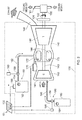
Figure 1 shows a schematic arrangement of a cooling medium supply system according to the present invention as applied to a machine; and -
Figure 2 shows a schematic arrangement of a cooling medium supply apparatus according to the present invention. - It is noted that the drawings are not to scale. The drawings are intended to depict only a typical aspect of the invention, and therefore should not be considered as limiting the scope of the invention.
- Referring to
Figures 1 and2 , a cooling medium supply apparatus according to an embodiment of the invention is designated generally by thereference numeral 10. - A
machine 20 is provided with a first cooling medium delivery means 30 and a second cooling medium delivery means 40 for the circulation of a cooling medium 110 through themachine 20. In this embodiment of the invention, the second cooling medium delivery means 40 takes the form of the coolingmedium supply apparatus 10. - The cooling
medium supply apparatus 10 comprises a coolingmedium pump mechanism 100 which is in fluid communication with a cooling medium 110, and a sensing means 120. - The sensing means 120 monitors a primary supply of the cooling medium 110 and is arranged to provide a signal indicative of a loss of the primary supply of the
cooling medium 110. In this embodiment, the sensing means 120 takes the form of a controller which monitors the primary supply of thecooling medium 110. - In this embodiment of the invention, the cooling
medium pump mechanism 100 is a conventional industrial liquid pump while the cooling medium 110 takes the form of water. Optionally the water may include various chemical additives, such as, for example, corrosion inhibitors, anti-foam additives and/or viscosity modifiers. - In other embodiments the cooling medium 110 may take the form of another liquid which is suitable for heat conduction applications such as, for example, ethylene glycol.
- The cooling
medium pump mechanism 100 is operatively connected by amechanical driveshaft 102 andclutch mechanism 104, to a self-contained gasturbine engine system 130. In other embodiments the coolingmedium pump mechanism 100 may be operatively connected to the gasturbine engine system 130 by an alternative power transmission means, such as, for example, a belt or chain drive. - The gas
turbine engine system 130 comprises agas turbine engine 140, a self-containedfuel supply 150, anignition system 170 and a startingsystem 180. - In the present embodiment, the
gas turbine engine 140 takes the form of a conventional single-shaft, industrial gas turbine engine which is sized to provide a sufficient shaft power output to match the power requirement of the coolingmedium pump mechanism 100. Thegas turbine engine 140 comprises, in axial flow series, anair intake 141, acompressor 142, a plurality ofcombustion chambers 144, aturbine 146 and anexhaust assembly 148. Thecompressor 142 andturbine 146 are connected together by an interconnectingshaft 143. - The
fuel supply 150 comprises a sealedcontainer 152 which contains a quantity of fuel. Afuel level gauge 154 is provided on thecontainer 152 to indicate the level status of thecontainer 152 to be deduced by an observer. - The
container 152 is connected to thecombustion chambers 144 via afuel supply pipe 162. Afuel flow valve 158, which is actuated by a fuelflow valve actuator 160, is positioned in thefuel supply pipe 162 between thecontainer 152 and thecombustion chambers 144. The fuelflow valve actuator 160 is controlled by the sensing means 120. - In the present embodiment, the
ignition system 170 comprises a plurality of catalyst elements (not shown) situated within thecombustion chambers 144. In an alternative embodiment, theignition system 170 may comprise a plurality of battery powered ignitor units. - The starting
system 180 comprises agas reservoir 182, containing a quantity of pressurised gas, agas supply pipe 190, agas flow valve 186 and a gasflow valve actuator 188. In the present embodiment, the gas is air. However, in alternative embodiments, the gas may be any gas which is capable of supporting combustion of the fuel, such as, for example, a mixture of air and oxygen. - The
gas flow valve 186 takes the form of a conventional motorised gas flow valve. Alternatively, a conventional bursting disc may be substituted for thegas flow valve 186. - Still further embodiments of the invention may comprise a starting
system 180 which employs a conventional cartridge starter mechanism. - A
pressure gauge 184 is provided on thegas reservoir 182 to provide an indication of the gas pressure in thegas reservoir 182. - The
gas supply pipe 190 directs a flow of the pressurised gas from thegas reservoir 182 into theintake 141 of thegas turbine engine 140. - In use, the sensing means 120 continually monitors the primary supply of the
cooling medium 110. When the sensing means 120 determines there to be a loss of the primary supply of the cooling medium 110, it transmits a first actuating signal to thepressure generating device 156. In response, thepressure generating device 156 then generates a gas pressure infuel container 152. - The sensing means 120 then transmits a second actuating signal to the fuel
flow valve actuator 160, which causes fuel to flow along thefuel supply pipe 162, through thefuel flow valve 158 and into thecombustion chambers 144. - At this stage, the sensing means 120 transmits a third actuating signal to the gas
flow valve actuator 188 which initiates a flow of the gas into theintake 141 of thegas turbine engine 140. This gas flow causes rotation of thecompressor 142 which results in a rotational speed of thegas turbine engine 140 increasing. - When the rotational speed of the
gas turbine engine 140 has reached a pre-determined starting threshold value, the sensing means transmits a fourth actuating signal to theignition system 170 which results in actuation of thegas turbine engine 140. - The
gas turbine engine 140 operates in a conventional manner so that air entering theintake 141 is compressed by thecompressor 142. The compressed air exhausted from thecompressor 142 is directed into thecombustion chambers 144 where it is mixed with fuel and the mixture combusted. The resultant hot combustion products then expand through, and thereby drive theturbine 146 before being exhausted through theexhaust 148. Theturbine 146 drives thecompressor 142 via interconnectingshaft 143. With thegas turbine engine 140 rotating at its normal operating speed, theclutch mechanism 104 may be actuated to provide a rotational drive to the coolingmedium pump mechanism 100. Operation of the cooling medium pump mechanism then provides a secondary flow of thecooling medium 110. - The
gas turbine engine 140 operates continuously until the supply of fuel contained in thefuel container 152 is exhausted, at which point the engine stops. - The foregoing description of various aspects of the invention has been presented for purposes of illustration and description. It is not intended to be exhaustive or to limit the invention to the precise form disclosed, and obviously, many modifications and variations are possible. Such modifications and variations that may be apparent to a person of skill in the art are included within the scope of the invention as defined by the accompanying claims.
Claims (7)
- A cooling medium supply apparatus (10) comprising:a cooling medium pump mechanism (100) in fluid communication with a cooling medium (110);a first cooling medium delivery means (30);a second cooling medium delivery means (40); anda sensing means (120) configured to provide a signal indicative of a loss of supply of the cooling medium (110) through the first cooling medium delivery means (30);wherein, in response to the signal, the cooling medium pump mechanism (100) is operable to deliver the cooling medium (110) through the second cooling medium delivery means (40).
- An apparatus as claimed in Claim 1, further comprising a self-contained gas turbine engine system (130) operatively connected to the cooling medium pump mechanism (100),
wherein, on receipt of the signal by the engine system (130), the engine system (130) is activated to thereby deliver the cooling medium (110) through the second cooling medium delivery means (40). - An apparatus as claimed in Claim 2, wherein the gas turbine engine system (130) comprises:a gas turbine engine (140);a self-contained fuel supply (150);an ignition system (170); anda starting system (180),wherein the fuel supply (150) comprises a pressurised fuel container (152), an internal pressure of the container (152) being greater than an external pressure of the container (152).
- An apparatus as claimed in Claim 3, wherein the fuel container (152) comprises a pressure generating device (156) that, on receipt of the signal by the engine system (130), is configured to cause the internal pressure to be greater than the external pressure.
- An apparatus as claimed in Claim 3 or Claim 4, wherein the starting system (180) comprises a pressurised gas reservoir (182) and a gas release valve (186), wherein receipt of the signal by the engine system causes actuation of the release valve (186) which causes the pressurised gas to be directed into an intake of the gas turbine engine (140) to thereby cause a rotational speed of the gas turbine engine (140) to increase to a starting value.
- A method of delivering a cooling medium supply to a machine (20), the method comprising the steps of:(a) sensing a loss of supply of a cooling medium (110) to the machine (20) through a first cooling medium delivery means (30):(b) generating a signal indicative of the loss of supply of the cooling medium (110); and(c) in response to the signal, activating a cooling medium pump mechanism (100) to deliver the cooling medium (110) to the machine (20) through a second cooling medium delivery means (40).
- A method as claimed in Claim 6, wherein the machine (20) comprises a gas turbine engine (140), a self-contained fuel supply (150), an ignition system (170) and a starting system (180), the gas turbine engine (140) being operatively connected to the cooling medium pump mechanism (100), and wherein step (b) comprises the steps of:(d) receipt of the signal by the machine (20);(e) in response to the signal, supplying the engine (140) with a fuel from a pressurised fuel container (152);(f) activating the starting system (180) to thereby activate the engine (140) to thereby cause the cooling medium pump mechanism (100) to deliver the cooling medium (110) to the machine (20) through a second cooling medium delivery means (40); and(g) operating the engine (140) until the fuel supply is exhausted.
Applications Claiming Priority (1)
| Application Number | Priority Date | Filing Date | Title |
|---|---|---|---|
| GBGB1208189.9A GB201208189D0 (en) | 2012-05-10 | 2012-05-10 | Method and apparatus for generating motive power |
Publications (3)
| Publication Number | Publication Date |
|---|---|
| EP2662553A2 true EP2662553A2 (en) | 2013-11-13 |
| EP2662553A3 EP2662553A3 (en) | 2017-05-03 |
| EP2662553B1 EP2662553B1 (en) | 2018-10-17 |
Family
ID=46396806
Family Applications (1)
| Application Number | Title | Priority Date | Filing Date |
|---|---|---|---|
| EP13166854.3A Active EP2662553B1 (en) | 2012-05-10 | 2013-05-07 | Cooling medium supply system and method |
Country Status (3)
| Country | Link |
|---|---|
| US (1) | US9353686B2 (en) |
| EP (1) | EP2662553B1 (en) |
| GB (1) | GB201208189D0 (en) |
Cited By (1)
| Publication number | Priority date | Publication date | Assignee | Title |
|---|---|---|---|---|
| CN113464215A (en) * | 2021-07-27 | 2021-10-01 | 辽宁红沿河核电有限公司 | Low-power cooling method and system for high and medium pressure cylinder of steam turbine |
Family Cites Families (12)
| Publication number | Priority date | Publication date | Assignee | Title |
|---|---|---|---|---|
| GB1132465A (en) * | 1965-05-10 | 1968-11-06 | English Electric Co Ltd | Nuclear reactors |
| JPS56165713A (en) * | 1980-05-21 | 1981-12-19 | Toyota Motor Corp | Cooler for engine |
| JPS57117739A (en) | 1981-01-16 | 1982-07-22 | Osaka Gas Co Ltd | Flow controlling apparatus for pumps used in cold water feeding apparatus |
| JPS6315318A (en) | 1986-07-07 | 1988-01-22 | Hitachi Ltd | computer cooling system |
| JPH0232298A (en) | 1988-07-22 | 1990-02-02 | Toshiba Corp | Nuclear reactor water feed controller |
| JP3039874B2 (en) | 1990-11-06 | 2000-05-08 | 株式会社日立製作所 | Reactor isolation cooling system |
| GB9904277D0 (en) * | 1999-02-25 | 1999-04-21 | Rolls Royce Plc | Gas turbine engine |
| US6481978B2 (en) * | 2001-01-03 | 2002-11-19 | York International Corp. | System and method for protecting turbine and compressor during shutdown |
| JP2004363286A (en) | 2003-06-04 | 2004-12-24 | Matsushita Electric Ind Co Ltd | Cooling device for semiconductor device |
| US7743740B2 (en) * | 2007-06-07 | 2010-06-29 | Brown Myron L | Automatic by-pass safety cooling system for fire pump engines |
| US20120036866A1 (en) * | 2010-08-11 | 2012-02-16 | Hamilton Sundstrand Corporation | Auxiliary power unit with multiple fuel sources |
| CN202103764U (en) | 2011-06-17 | 2012-01-04 | 北京同方吉兆科技有限公司 | Built-in liquid cooling device for television transmitter |
-
2012
- 2012-05-10 GB GBGB1208189.9A patent/GB201208189D0/en not_active Ceased
-
2013
- 2013-05-07 EP EP13166854.3A patent/EP2662553B1/en active Active
- 2013-05-07 US US13/888,969 patent/US9353686B2/en active Active
Cited By (1)
| Publication number | Priority date | Publication date | Assignee | Title |
|---|---|---|---|---|
| CN113464215A (en) * | 2021-07-27 | 2021-10-01 | 辽宁红沿河核电有限公司 | Low-power cooling method and system for high and medium pressure cylinder of steam turbine |
Also Published As
| Publication number | Publication date |
|---|---|
| EP2662553A3 (en) | 2017-05-03 |
| GB201208189D0 (en) | 2012-06-20 |
| EP2662553B1 (en) | 2018-10-17 |
| US20130298567A1 (en) | 2013-11-14 |
| US9353686B2 (en) | 2016-05-31 |
Similar Documents
| Publication | Publication Date | Title |
|---|---|---|
| US10125692B2 (en) | Gas turbine engine system having a disengageable electric machine | |
| EP4051882B1 (en) | Method for starting and stopping a closed-cycle turbomachine | |
| JP5214992B2 (en) | Engine pre-lubricating apparatus and method | |
| CA2643489C (en) | Gas turbine engine oil system operation | |
| EP1983174B1 (en) | Apparatus and method of operating a gas turbine engine at start-up | |
| RU2515912C2 (en) | Aircraft engine with electric starter cooling | |
| US11536202B2 (en) | Gas turbine engine turning system | |
| US20250207532A1 (en) | Passive auxiliary lubrication system | |
| EP3726012B1 (en) | Gas turbine engine generator oil pump | |
| CN106351744B (en) | Power augmentation system for gas turbine | |
| RU2660725C2 (en) | Aircraft gas turbine engine emergency starting system and method | |
| WO2009140100A1 (en) | Method and apparatus for controlling fuel in a gas turbine engine | |
| KR20130086340A (en) | A non-lubricated architecture for a turboshaft engine | |
| EP4311777A1 (en) | Multi-drive unit powerplant for an aircraft | |
| US9353686B2 (en) | Method and apparatus for generating motive power | |
| RU2480600C1 (en) | Oil system of power gas turbine plant | |
| JP4121954B2 (en) | Turbine controller inspection equipment | |
| JP2010077856A (en) | Emergency diesel generator facility and its operation method | |
| JP5889075B2 (en) | Lubricating oil supply system and temporary oil pump | |
| JP2015068300A (en) | Power generation plant | |
| SU694943A1 (en) | Arrangement for oil supply of shaft seals in a turbogenerator with hydrogen cooling | |
| JP2019210870A (en) | Emergency diesel power generation facility, heated water supply pump used in the same, lubrication oil supply pump, and air driving power generator | |
| JP2003336503A (en) | Gas turbine device | |
| RU120145U1 (en) | GAS TURBINE UNIT WITH ENERGY STORAGE | |
| KR20260062809A (en) | Method for reactivating a combustion engine in standby mode during an asymmetric operating mode in a multi-engine aircraft |
Legal Events
| Date | Code | Title | Description |
|---|---|---|---|
| PUAI | Public reference made under article 153(3) epc to a published international application that has entered the european phase |
Free format text: ORIGINAL CODE: 0009012 |
|
| AK | Designated contracting states |
Kind code of ref document: A2 Designated state(s): AL AT BE BG CH CY CZ DE DK EE ES FI FR GB GR HR HU IE IS IT LI LT LU LV MC MK MT NL NO PL PT RO RS SE SI SK SM TR |
|
| AX | Request for extension of the european patent |
Extension state: BA ME |
|
| RAP1 | Party data changed (applicant data changed or rights of an application transferred) |
Owner name: ROLLS-ROYCE PLC |
|
| PUAL | Search report despatched |
Free format text: ORIGINAL CODE: 0009013 |
|
| AK | Designated contracting states |
Kind code of ref document: A3 Designated state(s): AL AT BE BG CH CY CZ DE DK EE ES FI FR GB GR HR HU IE IS IT LI LT LU LV MC MK MT NL NO PL PT RO RS SE SI SK SM TR |
|
| AX | Request for extension of the european patent |
Extension state: BA ME |
|
| RIC1 | Information provided on ipc code assigned before grant |
Ipc: F02C 7/12 20060101AFI20170330BHEP Ipc: F01D 25/12 20060101ALI20170330BHEP Ipc: F02C 6/00 20060101ALI20170330BHEP |
|
| STAA | Information on the status of an ep patent application or granted ep patent |
Free format text: STATUS: REQUEST FOR EXAMINATION WAS MADE |
|
| 17P | Request for examination filed |
Effective date: 20171103 |
|
| RBV | Designated contracting states (corrected) |
Designated state(s): AL AT BE BG CH CY CZ DE DK EE ES FI FR GB GR HR HU IE IS IT LI LT LU LV MC MK MT NL NO PL PT RO RS SE SI SK SM TR |
|
| REG | Reference to a national code |
Ref country code: DE Ref legal event code: R079 Ref document number: 602013045124 Country of ref document: DE Free format text: PREVIOUS MAIN CLASS: F02C0007160000 Ipc: F02C0007120000 |
|
| GRAP | Despatch of communication of intention to grant a patent |
Free format text: ORIGINAL CODE: EPIDOSNIGR1 |
|
| STAA | Information on the status of an ep patent application or granted ep patent |
Free format text: STATUS: GRANT OF PATENT IS INTENDED |
|
| RIC1 | Information provided on ipc code assigned before grant |
Ipc: F01D 25/12 20060101ALI20180411BHEP Ipc: F01D 15/08 20060101ALI20180411BHEP Ipc: F02C 6/00 20060101ALI20180411BHEP Ipc: F02C 7/12 20060101AFI20180411BHEP |
|
| INTG | Intention to grant announced |
Effective date: 20180509 |
|
| GRAS | Grant fee paid |
Free format text: ORIGINAL CODE: EPIDOSNIGR3 |
|
| GRAA | (expected) grant |
Free format text: ORIGINAL CODE: 0009210 |
|
| STAA | Information on the status of an ep patent application or granted ep patent |
Free format text: STATUS: THE PATENT HAS BEEN GRANTED |
|
| AK | Designated contracting states |
Kind code of ref document: B1 Designated state(s): AL AT BE BG CH CY CZ DE DK EE ES FI FR GB GR HR HU IE IS IT LI LT LU LV MC MK MT NL NO PL PT RO RS SE SI SK SM TR |
|
| REG | Reference to a national code |
Ref country code: GB Ref legal event code: FG4D |
|
| REG | Reference to a national code |
Ref country code: CH Ref legal event code: EP |
|
| REG | Reference to a national code |
Ref country code: IE Ref legal event code: FG4D |
|
| REG | Reference to a national code |
Ref country code: DE Ref legal event code: R096 Ref document number: 602013045124 Country of ref document: DE Ref country code: AT Ref legal event code: REF Ref document number: 1054312 Country of ref document: AT Kind code of ref document: T Effective date: 20181115 |
|
| REG | Reference to a national code |
Ref country code: NL Ref legal event code: MP Effective date: 20181017 |
|
| REG | Reference to a national code |
Ref country code: LT Ref legal event code: MG4D |
|
| REG | Reference to a national code |
Ref country code: AT Ref legal event code: MK05 Ref document number: 1054312 Country of ref document: AT Kind code of ref document: T Effective date: 20181017 |
|
| PG25 | Lapsed in a contracting state [announced via postgrant information from national office to epo] |
Ref country code: NL Free format text: LAPSE BECAUSE OF FAILURE TO SUBMIT A TRANSLATION OF THE DESCRIPTION OR TO PAY THE FEE WITHIN THE PRESCRIBED TIME-LIMIT Effective date: 20181017 |
|
| PG25 | Lapsed in a contracting state [announced via postgrant information from national office to epo] |
Ref country code: FI Free format text: LAPSE BECAUSE OF FAILURE TO SUBMIT A TRANSLATION OF THE DESCRIPTION OR TO PAY THE FEE WITHIN THE PRESCRIBED TIME-LIMIT Effective date: 20181017 Ref country code: NO Free format text: LAPSE BECAUSE OF FAILURE TO SUBMIT A TRANSLATION OF THE DESCRIPTION OR TO PAY THE FEE WITHIN THE PRESCRIBED TIME-LIMIT Effective date: 20190117 Ref country code: IS Free format text: LAPSE BECAUSE OF FAILURE TO SUBMIT A TRANSLATION OF THE DESCRIPTION OR TO PAY THE FEE WITHIN THE PRESCRIBED TIME-LIMIT Effective date: 20190217 Ref country code: HR Free format text: LAPSE BECAUSE OF FAILURE TO SUBMIT A TRANSLATION OF THE DESCRIPTION OR TO PAY THE FEE WITHIN THE PRESCRIBED TIME-LIMIT Effective date: 20181017 Ref country code: LT Free format text: LAPSE BECAUSE OF FAILURE TO SUBMIT A TRANSLATION OF THE DESCRIPTION OR TO PAY THE FEE WITHIN THE PRESCRIBED TIME-LIMIT Effective date: 20181017 Ref country code: BG Free format text: LAPSE BECAUSE OF FAILURE TO SUBMIT A TRANSLATION OF THE DESCRIPTION OR TO PAY THE FEE WITHIN THE PRESCRIBED TIME-LIMIT Effective date: 20190117 Ref country code: PL Free format text: LAPSE BECAUSE OF FAILURE TO SUBMIT A TRANSLATION OF THE DESCRIPTION OR TO PAY THE FEE WITHIN THE PRESCRIBED TIME-LIMIT Effective date: 20181017 Ref country code: ES Free format text: LAPSE BECAUSE OF FAILURE TO SUBMIT A TRANSLATION OF THE DESCRIPTION OR TO PAY THE FEE WITHIN THE PRESCRIBED TIME-LIMIT Effective date: 20181017 Ref country code: LV Free format text: LAPSE BECAUSE OF FAILURE TO SUBMIT A TRANSLATION OF THE DESCRIPTION OR TO PAY THE FEE WITHIN THE PRESCRIBED TIME-LIMIT Effective date: 20181017 Ref country code: AT Free format text: LAPSE BECAUSE OF FAILURE TO SUBMIT A TRANSLATION OF THE DESCRIPTION OR TO PAY THE FEE WITHIN THE PRESCRIBED TIME-LIMIT Effective date: 20181017 |
|
| PG25 | Lapsed in a contracting state [announced via postgrant information from national office to epo] |
Ref country code: PT Free format text: LAPSE BECAUSE OF FAILURE TO SUBMIT A TRANSLATION OF THE DESCRIPTION OR TO PAY THE FEE WITHIN THE PRESCRIBED TIME-LIMIT Effective date: 20190217 Ref country code: AL Free format text: LAPSE BECAUSE OF FAILURE TO SUBMIT A TRANSLATION OF THE DESCRIPTION OR TO PAY THE FEE WITHIN THE PRESCRIBED TIME-LIMIT Effective date: 20181017 Ref country code: RS Free format text: LAPSE BECAUSE OF FAILURE TO SUBMIT A TRANSLATION OF THE DESCRIPTION OR TO PAY THE FEE WITHIN THE PRESCRIBED TIME-LIMIT Effective date: 20181017 Ref country code: GR Free format text: LAPSE BECAUSE OF FAILURE TO SUBMIT A TRANSLATION OF THE DESCRIPTION OR TO PAY THE FEE WITHIN THE PRESCRIBED TIME-LIMIT Effective date: 20190118 Ref country code: SE Free format text: LAPSE BECAUSE OF FAILURE TO SUBMIT A TRANSLATION OF THE DESCRIPTION OR TO PAY THE FEE WITHIN THE PRESCRIBED TIME-LIMIT Effective date: 20181017 |
|
| REG | Reference to a national code |
Ref country code: DE Ref legal event code: R097 Ref document number: 602013045124 Country of ref document: DE |
|
| PG25 | Lapsed in a contracting state [announced via postgrant information from national office to epo] |
Ref country code: IT Free format text: LAPSE BECAUSE OF FAILURE TO SUBMIT A TRANSLATION OF THE DESCRIPTION OR TO PAY THE FEE WITHIN THE PRESCRIBED TIME-LIMIT Effective date: 20181017 Ref country code: DK Free format text: LAPSE BECAUSE OF FAILURE TO SUBMIT A TRANSLATION OF THE DESCRIPTION OR TO PAY THE FEE WITHIN THE PRESCRIBED TIME-LIMIT Effective date: 20181017 Ref country code: CZ Free format text: LAPSE BECAUSE OF FAILURE TO SUBMIT A TRANSLATION OF THE DESCRIPTION OR TO PAY THE FEE WITHIN THE PRESCRIBED TIME-LIMIT Effective date: 20181017 |
|
| PLBE | No opposition filed within time limit |
Free format text: ORIGINAL CODE: 0009261 |
|
| STAA | Information on the status of an ep patent application or granted ep patent |
Free format text: STATUS: NO OPPOSITION FILED WITHIN TIME LIMIT |
|
| PG25 | Lapsed in a contracting state [announced via postgrant information from national office to epo] |
Ref country code: SK Free format text: LAPSE BECAUSE OF FAILURE TO SUBMIT A TRANSLATION OF THE DESCRIPTION OR TO PAY THE FEE WITHIN THE PRESCRIBED TIME-LIMIT Effective date: 20181017 Ref country code: RO Free format text: LAPSE BECAUSE OF FAILURE TO SUBMIT A TRANSLATION OF THE DESCRIPTION OR TO PAY THE FEE WITHIN THE PRESCRIBED TIME-LIMIT Effective date: 20181017 Ref country code: EE Free format text: LAPSE BECAUSE OF FAILURE TO SUBMIT A TRANSLATION OF THE DESCRIPTION OR TO PAY THE FEE WITHIN THE PRESCRIBED TIME-LIMIT Effective date: 20181017 Ref country code: SM Free format text: LAPSE BECAUSE OF FAILURE TO SUBMIT A TRANSLATION OF THE DESCRIPTION OR TO PAY THE FEE WITHIN THE PRESCRIBED TIME-LIMIT Effective date: 20181017 |
|
| 26N | No opposition filed |
Effective date: 20190718 |
|
| PG25 | Lapsed in a contracting state [announced via postgrant information from national office to epo] |
Ref country code: SI Free format text: LAPSE BECAUSE OF FAILURE TO SUBMIT A TRANSLATION OF THE DESCRIPTION OR TO PAY THE FEE WITHIN THE PRESCRIBED TIME-LIMIT Effective date: 20181017 |
|
| REG | Reference to a national code |
Ref country code: CH Ref legal event code: PL |
|
| PG25 | Lapsed in a contracting state [announced via postgrant information from national office to epo] |
Ref country code: LI Free format text: LAPSE BECAUSE OF NON-PAYMENT OF DUE FEES Effective date: 20190531 Ref country code: MC Free format text: LAPSE BECAUSE OF FAILURE TO SUBMIT A TRANSLATION OF THE DESCRIPTION OR TO PAY THE FEE WITHIN THE PRESCRIBED TIME-LIMIT Effective date: 20181017 Ref country code: CH Free format text: LAPSE BECAUSE OF NON-PAYMENT OF DUE FEES Effective date: 20190531 |
|
| REG | Reference to a national code |
Ref country code: BE Ref legal event code: MM Effective date: 20190531 |
|
| PG25 | Lapsed in a contracting state [announced via postgrant information from national office to epo] |
Ref country code: LU Free format text: LAPSE BECAUSE OF NON-PAYMENT OF DUE FEES Effective date: 20190507 |
|
| PG25 | Lapsed in a contracting state [announced via postgrant information from national office to epo] |
Ref country code: TR Free format text: LAPSE BECAUSE OF FAILURE TO SUBMIT A TRANSLATION OF THE DESCRIPTION OR TO PAY THE FEE WITHIN THE PRESCRIBED TIME-LIMIT Effective date: 20181017 |
|
| PG25 | Lapsed in a contracting state [announced via postgrant information from national office to epo] |
Ref country code: IE Free format text: LAPSE BECAUSE OF NON-PAYMENT OF DUE FEES Effective date: 20190507 |
|
| PG25 | Lapsed in a contracting state [announced via postgrant information from national office to epo] |
Ref country code: BE Free format text: LAPSE BECAUSE OF NON-PAYMENT OF DUE FEES Effective date: 20190531 |
|
| PG25 | Lapsed in a contracting state [announced via postgrant information from national office to epo] |
Ref country code: CY Free format text: LAPSE BECAUSE OF FAILURE TO SUBMIT A TRANSLATION OF THE DESCRIPTION OR TO PAY THE FEE WITHIN THE PRESCRIBED TIME-LIMIT Effective date: 20181017 |
|
| PG25 | Lapsed in a contracting state [announced via postgrant information from national office to epo] |
Ref country code: MT Free format text: LAPSE BECAUSE OF FAILURE TO SUBMIT A TRANSLATION OF THE DESCRIPTION OR TO PAY THE FEE WITHIN THE PRESCRIBED TIME-LIMIT Effective date: 20181017 Ref country code: HU Free format text: LAPSE BECAUSE OF FAILURE TO SUBMIT A TRANSLATION OF THE DESCRIPTION OR TO PAY THE FEE WITHIN THE PRESCRIBED TIME-LIMIT; INVALID AB INITIO Effective date: 20130507 |
|
| PG25 | Lapsed in a contracting state [announced via postgrant information from national office to epo] |
Ref country code: MK Free format text: LAPSE BECAUSE OF FAILURE TO SUBMIT A TRANSLATION OF THE DESCRIPTION OR TO PAY THE FEE WITHIN THE PRESCRIBED TIME-LIMIT Effective date: 20181017 |
|
| P01 | Opt-out of the competence of the unified patent court (upc) registered |
Effective date: 20230528 |
|
| PGFP | Annual fee paid to national office [announced via postgrant information from national office to epo] |
Ref country code: DE Payment date: 20250528 Year of fee payment: 13 |
|
| PGFP | Annual fee paid to national office [announced via postgrant information from national office to epo] |
Ref country code: FR Payment date: 20250526 Year of fee payment: 13 |
|
| PGFP | Annual fee paid to national office [announced via postgrant information from national office to epo] |
Ref country code: GB Payment date: 20260313 Year of fee payment: 14 |