EP2662312A1 - A package for drills, a method and an arrangement therefore - Google Patents
A package for drills, a method and an arrangement therefore Download PDFInfo
- Publication number
- EP2662312A1 EP2662312A1 EP12167150.7A EP12167150A EP2662312A1 EP 2662312 A1 EP2662312 A1 EP 2662312A1 EP 12167150 A EP12167150 A EP 12167150A EP 2662312 A1 EP2662312 A1 EP 2662312A1
- Authority
- EP
- European Patent Office
- Prior art keywords
- drill
- package
- protecting
- locking portion
- locking
- Prior art date
- Legal status (The legal status is an assumption and is not a legal conclusion. Google has not performed a legal analysis and makes no representation as to the accuracy of the status listed.)
- Granted
Links
Images

Classifications
-
- B—PERFORMING OPERATIONS; TRANSPORTING
- B65—CONVEYING; PACKING; STORING; HANDLING THIN OR FILAMENTARY MATERIAL
- B65D—CONTAINERS FOR STORAGE OR TRANSPORT OF ARTICLES OR MATERIALS, e.g. BAGS, BARRELS, BOTTLES, BOXES, CANS, CARTONS, CRATES, DRUMS, JARS, TANKS, HOPPERS, FORWARDING CONTAINERS; ACCESSORIES, CLOSURES, OR FITTINGS THEREFOR; PACKAGING ELEMENTS; PACKAGES
- B65D85/00—Containers, packaging elements or packages, specially adapted for particular articles or materials
- B65D85/20—Containers, packaging elements or packages, specially adapted for particular articles or materials for incompressible or rigid rod-shaped or tubular articles
-
- A—HUMAN NECESSITIES
- A61—MEDICAL OR VETERINARY SCIENCE; HYGIENE
- A61C—DENTISTRY; APPARATUS OR METHODS FOR ORAL OR DENTAL HYGIENE
- A61C19/00—Dental auxiliary appliances
- A61C19/02—Protective casings, e.g. boxes for instruments; Bags
-
- A—HUMAN NECESSITIES
- A61—MEDICAL OR VETERINARY SCIENCE; HYGIENE
- A61B—DIAGNOSIS; SURGERY; IDENTIFICATION
- A61B50/00—Containers, covers, furniture or holders specially adapted for surgical or diagnostic appliances or instruments, e.g. sterile covers
- A61B50/30—Containers specially adapted for packaging, protecting, dispensing, collecting or disposing of surgical or diagnostic appliances or instruments
-
- A—HUMAN NECESSITIES
- A61—MEDICAL OR VETERINARY SCIENCE; HYGIENE
- A61C—DENTISTRY; APPARATUS OR METHODS FOR ORAL OR DENTAL HYGIENE
- A61C3/00—Dental tools or instruments
- A61C3/04—Supports for holding tooth drills in order of use
-
- B—PERFORMING OPERATIONS; TRANSPORTING
- B65—CONVEYING; PACKING; STORING; HANDLING THIN OR FILAMENTARY MATERIAL
- B65D—CONTAINERS FOR STORAGE OR TRANSPORT OF ARTICLES OR MATERIALS, e.g. BAGS, BARRELS, BOTTLES, BOXES, CANS, CARTONS, CRATES, DRUMS, JARS, TANKS, HOPPERS, FORWARDING CONTAINERS; ACCESSORIES, CLOSURES, OR FITTINGS THEREFOR; PACKAGING ELEMENTS; PACKAGES
- B65D25/00—Details of other kinds or types of rigid or semi-rigid containers
- B65D25/02—Internal fittings
- B65D25/10—Devices to locate articles in containers
- B65D25/103—V-shaped elements, e.g. racks, protuberances projecting from a supporting surface, supporting the articles locally at its sides
- B65D25/105—V-shaped elements, e.g. racks, protuberances projecting from a supporting surface, supporting the articles locally at its sides and retaining it by snap-action, e.g. clips
-
- B—PERFORMING OPERATIONS; TRANSPORTING
- B65—CONVEYING; PACKING; STORING; HANDLING THIN OR FILAMENTARY MATERIAL
- B65D—CONTAINERS FOR STORAGE OR TRANSPORT OF ARTICLES OR MATERIALS, e.g. BAGS, BARRELS, BOTTLES, BOXES, CANS, CARTONS, CRATES, DRUMS, JARS, TANKS, HOPPERS, FORWARDING CONTAINERS; ACCESSORIES, CLOSURES, OR FITTINGS THEREFOR; PACKAGING ELEMENTS; PACKAGES
- B65D85/00—Containers, packaging elements or packages, specially adapted for particular articles or materials
- B65D85/20—Containers, packaging elements or packages, specially adapted for particular articles or materials for incompressible or rigid rod-shaped or tubular articles
- B65D85/24—Containers, packaging elements or packages, specially adapted for particular articles or materials for incompressible or rigid rod-shaped or tubular articles for needles, nails or like elongate small articles
Definitions
- the present invention relates to a package for a drill, such as a surgical drill, e.g. a dental drill.
- the invention also relates to an arrangement comprising a drill and such package.
- the invention relates to a method for releasing a drill from such package.
- the invention also relates to a method for connecting a drill held in such package to a tool holding fixture.
- Drills such as dental drills, should be protected from impacts since the sharp edges of the drill are easily impaired. Furthermore, dental drills need to be kept in a sterile environment until shortly before use. The cutting region of the drill (i.e. the bit) is especially associated with high demands of sterility. Therefore there are high demands on the drill's packaging.
- DE-A-102005022385 discloses an individual packaging case for objects with fracture risk.
- This packaging case comprises a base with an open, upward-pointing receiving bore, into which the shank of the object with fracture risk is inserted and self-containedly protrudes from the bore.
- the fragile particle is protected by means of a protective cap.
- the packaging case is foldable over an axis running perpendicular to the longitudinal axis and due to the folding, the object to be protected becomes at least partly freely accessible.
- a problem with this kind of packaging case is that it needs to be very clean in order to prevent contamination of the object since the cutting edges of the drill is not fastened to the package in a contact free manner. Unless the drill is properly arranged in the package, there may be a risk of the drill wobbling and repeatedly impinging against the package during transport and handling of the package. In such case, the drill may be contaminated by particles of the packaging material which may become cut away and subsequently be transferred with the drill into the oral cavity of a patient, which is undesirable.
- a package housing for an elongate object includes a base element having a housing wall.
- the base element comprises a head part and a holding part connected to each other by a weakening zone, the latter is a predetermined breaking zone.
- the holding part includes a holding portion which is intended to hold the object in the holding part.
- the holding portion includes a spacer such that the object can be held in a contact-free manner with respect to the housing wall.
- An object of the invention is therefore to overcome the above problems, and to provide a package for a drill which is easy to handle during the connection of the drill to a tool holding fixture.
- the present invention is based on the insight that a cutting portion of a drill may be held out of contact from the package until the time of installation of the drill into a tool holding fixture, at which time a user may clamp the cutting portion of the drill with the package to hold and guide the drill into the tool holding fixture.
- a user may clamp the cutting portion of the drill with the package to hold and guide the drill into the tool holding fixture.
- repeated impinging of the drill against the package is avoided while allowing a controlled one-time gripping of the drill, which is not believed to cause the above mentioned cutting-away of packaging material.
- this results in an easier handling during the installation of the drill into a tool holding fixture, while still maintaining a satisfactory level of sterility and patient safety.
- the inventor has realized that if while clamping the cutting portion of the drill, release of the drill from its package can easily be accomplished if the part of the package securing a tool engaging portion of the drill, i.e. a locking portion of the package, is moved relative the protecting portion of the package.
- the drill can be inserted into a tool holding fixture in an easy manner and with full control of the user.
- a package for a drill comprises
- the user fixates the drill by pressing the first and/or the second subportion(s) of the protecting portion an easy connection of the drill to a tool holding fixture is possible, without the need for the user to touch the cutting portion of the drill.
- the user may fixate the drill after the drill has been released from the locking portion.
- the user may fixate the drill prior to the releasing movement of the locking portion, which is advantageous since the clamping fixation of the cutting portion facilitates the release of the drill from the locking portion when the locking portion is moved relative to the protecting portion.
- the cutting portion is the part of the drill not being the tool engaging portion of the drill.
- the cutting portion generally comprises the sharp edges of the drill (the bit), which can be located along the longitudinal axis of the drill or perpendicular to the axis of the drill or located in another direction, while the tool engaging portion generally comprises the shank of the drill.
- the drill and the tool holding fixture are two different objects.
- the drill is here defined as the object used for creating a bore hole and being in direct contact with the matter cut or pressed away, while the tool holding fixture is the equipment to which the drill is to be connected.
- the tool holding fixture may be a drilling apparatus used by e.g. a dentist.
- the protecting portion has at least two functions, one being to house the cutting portion of the drill in a contact-free manner, thereby avoiding sharp edges from contact with the package during storage and transport. This ensures that the drill is kept away from possible contaminations.
- a second function is to provide a portion allowing the user to clamp the drill by pressing the outer surface of that portion. It should be noted that the protecting portion may house only a part of the cutting portion of the drill. However, the protecting portion may also completely house the cutting portion of the drill.
- the locking portion and the protecting portion are movable relative each other.
- the drill can be released from the locking portion by fixing the drill in the protecting portion and subsequently, or prior to fixing the drill in the protecting portion, establishing a movement of the protecting portion relative the locking portion.
- the package can be regarded as having two drill fixating portions.
- One drill fixating portion would be the locking portion which is intended to initially fixate the drill during storage.
- the other one would be the protecting portion which is intended to temporarily fixate the drill by manual force while the drill is connected to a tool holding fixture.
- the package according to the invention allows for a change from the locking portion's non-manual fixation of the drill to the protecting portion's manual fixation of the drill.
- the first subportion is made in one piece with the second subportion of the protecting portion, i.e. they are integral with each other.
- the protecting portion may, for instance, be made by injection moulding or vacuum forming.
- the second subportion is a continuation of the first subportion, without any intermediate portion there between.
- the first subportion and the second subportion are connected by means of a distal package portion, the distal package portion being a continuation of the first subportion and the second subportion being a continuation of the distal package portion.
- the protecting portion is made in one piece with the locking portion.
- the protecting portion and the locking portion may, for instance, be made by injection moulding or vacuum forming.
- the whole package is made in one piece by e.g. injection moulding or vacuum forming.
- the package is an inner package adapted to be contained in an outer package.
- the inner package may be sterilized together with the drill while the outer surface of the outer package may be non-sterile.
- the outer package may then also assure sterility by protecting the drill and its inner package from outer contamination.
- the movement of the locking portion relative the protecting portion while the cutting portion of the drill is clamped results in the release of the tool engaging portion of the drill from the locking portion.
- the movement of the locking portion, and thus the release of the drill occurs prior to the clamping of the cutting portion of the drill. This may be achieved by the package itself, for instance, during the movement of the locking portion the drill may become tilted so that the cutting portion abuts the walls of the protecting portion.
- a counterforce similar to when clamping the drill, is exerted on the drill by the walls of the package, thus allowing for the release of the drill with the continued relative movement between the locking portion and the protecting portion.
- At least one of the first and the second subportions of the protecting portion is made from a flexible material.
- other parts of the package are made from a flexible material.
- the flexible material may be plastic, but it may also be other materials, such as rubber, paper or thin metal foil.
- a non-flexible part of the package may provide for increased rigidity and stability of the package.
- two different parts of the package may be made from a flexible material.
- the first flexible part may be a part of the protecting portion which enables the user to clamp the drill in the before mentioned manner, while the second flexible part may allow for the movement between the protecting portion and the locking portion, e.g. by a bending movement.
- the remaining parts of the package may be made from a non-flexible material.
- the risk for a part of the package to flex back is reduced.
- having parts of the package made from a non-flexible material reduces the risk of the package prematurely coming into contact with the sharp edges of the drill.
- a package may still be made in one piece, where some portions are made thicker, e.g. so thick that the user cannot bend or flex such portions (i.e. not flexible portions) with his/her fingers while some portions are made thinner, e.g. thin enough for a user to bend or flex such portions (i.e. flexible portions) with his/her fingers.
- the package may be made partly flexible.
- a cheap and functional package may be made. Also using plastic material facilitates the manufacturing process since the package may be produced by injection moulding, vacuum forming etc.
- the user may clamp the protecting portion and thereby establish a contact between the package and at least a part of the drill by other means than having the package at least partly made from a flexible material.
- the first subportion may be allowed to be moved towards the second subportion by means of a hinge.
- the first and the second subportions of the protecting portion may be rigidly constructed.
- the protecting portion has a U-shaped cross-section around the cutting portion of the drill.
- the first and second subportions of the protecting portion form the two legs of the U-shape.
- a space is formed between the drill and the central connecting distal package portion of the "U-shape" of the package.
- the first and second subportions are formed as elongated legs.
- the first and second subportion may have other shapes, for instance, the shape of a square. Such shapes may be advantageous, for instance, for accommodating several drills arranged in parallel with each other and held by respective locking portions.
- the locking portion comprises a snap lock.
- the use of a snap lock is advantageous since it is possible to integrate the locking means with the remaining package. Hereby also the manufacturing process is facilitated since a snap lock is possible to produce by injection moulding.
- a snap lock is further advantageous since it may be designed strong enough for holding the drill securely during storage and transport, and yet weak enough to enables the drill to be released using a relatively small force.
- the use of a snap lock does not limit the invention, the drill could be fastened by other means, such as a mechanical lock.
- the mechanical lock may contain the tool engaging portion of the drill by means of a foldable cap. Unfolding the cap from the engaging portion of the drill may then result in the release of the drill from the package.
- the package is adapted such that the movement of the locking portion relative the protecting portion may be achieved by bending the package.
- the relative movement between the locking portion and the protecting portion is carried out in a simple manner.
- the bending movement is especially suitable for sections of the package made from a flexible material.
- the package is adapted such that the relative movement between the locking portion and the protecting portion may be achieved by pivoting the locking portion around an axis that is perpendicular to the longitudinal axis of the package.
- the package is adapted such that the relative movement between the locking portion and the protecting portion may be achieved by pivoting the locking portion around the longitudinal axis of the package. It should be understood that the function of the relative movement between the locking portion and the protecting portion is to release the drill from the locking portion. This could be achieved by any other suitable type of relative movement between the locking portion and the protecting portion.
- the package further comprises a gripping portion located adjacent the locking portion.
- the gripping portion has the advantage that it facilitates handling of the package by allowing the user to hold a specific part of the package. This is advantageous for example when the user removes the package from an outer package and also when the user removes the drill from the package. Hereby, the user can avoid unintentional touching of the drill.
- the gripping portion is located in close proximity of the locking portion.
- the gripping portion is located opposite the protecting portion such that the locking portion is located between the gripping portion and the protecting portion.
- the gripping portion is juxtapositioned the locking portion.
- the gripping portion is designed such that it is integrated with the locking portion.
- the gripping portion is located between the locking portion and a distal end of the protecting portion.
- the gripping portion is designed as a lip.
- the user can easily grip the lip by using a thumb and another finger.
- This type of grip is advantageously when the user removes the inner package from the outer package and also when the user removes the drill from the package.
- the package is adapted such that the relative movement between the locking portion and the protecting portion may be achieved by a movement of the gripping portion away from the longitudinal axis of the package.
- the drill can be released from the locking portion by for example bending the package.
- a method for releasing a drill from a package comprising a protecting portion housing a cutting portion of the drill in a contact free manner and a locking portion holding a tool engaging portion of the drill, the method comprising the steps of clamping the drill by pressing the protecting portion; releasing the drill from the locking portion by moving the locking portion relative the protecting portion while maintaining the clamping of the drill.
- the package may partly be made in a flexible material and/or be made in one piece.
- a method is provided wherein the movement of the locking portion relative the protecting portion is achieved by bending the package.
- a method wherein the relative movement between the locking portion and the protecting portion is achieved by pivoting the locking portion around an axis that is perpendicular to the longitudinal axis of the package.
- a method wherein the package further comprises a gripping portion located adjacent to the locking portion.
- the relative movement between the locking portion and the protecting portion may thus be achieved by a movement of the gripping portion away from the longitudinal axis of the package.
- a method for connecting to a tool holding fixture a drill held in a package comprising a protecting portion housing a cutting portion of the drill in a contact free manner and a locking portion holding a tool engaging portion of the drill, the method comprising the steps of releasing the drill from the locking portion by moving the locking portion relative the protecting portion, and clamping the drill by pressing the protecting portion wherein the clamping is performed prior, after or during the step of releasing the drill, and connecting, while maintaining the clamping of the drill, the tool engaging portion of the drill to the tool holding fixture.
- the package may partly be made in a flexible material and/or be made in one piece.
- an arrangement comprising a package according to the first aspect and a drill.
- the protecting portion of the package houses a cutting portion of the drill in a contact free manner, and wherein the locking portion of the package holds a tool engaging portion of the drill, and wherein the locking portion and the protecting portion are movable relative each other, and wherein the drill is releasable from the locking portion by a movement of the locking portion relative the protecting portion, and wherein the protecting portion comprises a first subportion and a second subportion arranged to allow the user to clamp the tool engaging portion of the drill by pressing the first subportion towards the second subportion and thereby establishing a contact between the protecting portion and the cutting portion of the drill.
- the movement of the locking portion relative the protecting portion while the cutting portion of the drill is clamped results in the release of the tool engaging portion of the drill from the locking portion.
- the movement of the locking portion, and thus the release of the drill occurs prior to the clamping of the cutting portion of the drill. This may be achieved by that the package itself withholds the drill by for example the walls of the protecting portion. Hereby a counterforce, similar to when clamping the drill, is exerted on the drill by the walls of the package, thus allowing for the release of the drill with the relative movement between the locking portion and the protecting portion.
- the package may partly be made in a flexible material and/or be made in one piece.
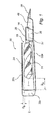
- Fig. 1 illustrates an arrangement comprising a drill 10 and a package 30 according to at least one example embodiment of the invention.
- the package 30 in Fig. 1 comprises a protecting portion 34, a locking portion 36 and a gripping portion 38, wherein the package 30 has a geometrical longitudinal axis L.
- the drill 10 is secured to the locking portion 36 of the package 30 in such manner that the its geometrical longitudinal axis I coincides or is parallel with the longitudinal axis L of the package 30.
- the protecting portion 34 is arranged to house a cutting portion 14 of the drill 10 in a contact free manner. This is illustrated by a gap Ga located along the longitudinal axis L, and a gap Gb located radially of the longitudinal axis L, both gaps Ga, Gb being defined by the protecting portion 34 and the cutting portion 14 of the drill 10.
- the protecting portion 34 is substantially U-shaped. The U-shape forms part of first and second subportions in the form of an elongated first leg 32a and an elongated second leg 32b of the package 30, which legs 32a, 32b are linked by a relatively short distal package portion 32c.
- the first subportion or leg 32a is longer than the second subportion or leg 32b and provides a base from which the locking portion 36 projects. Also, the end of the first leg 32a may be provided with a curve 48 to form the gripping portion 38.
- the first leg 32a, the second leg 32b and the linking distal portion 32c may all be flexible. Alternatively, it would be conceivable to only have one leg flexible (e.g. the first leg 32a) and the other rigid (e.g. the second leg 32b).
- the illustrated package 30 is open laterally, in other embodiments it would be conceivable to have one or more lateral sidewalls (33a-33c shown in fig 3a-3b ), which interconnect the first leg 32a with the second leg 32b similarly to the distal package portion 32c, thus further enclosing/concealing the cutting portion 14 of the drill 10.
- lateral sidewalls do not necessarily have to interconnect the legs 32a, 32b, but could for instance extend from the second leg 32b downwards towards but not all the way to the first leg 32a.
- the locking portion 36 is arranged to hold the tool engaging portion 16 of the drill 10.
- the locking portion 36 comprises a snap lock 37.
- the locking portion 36 in Figs. 1-2 comprises a snap lock 37, locking by other means are possible.
- the gripping portion 38 is located adjacent the locking portion 36 and may be constructed in various manners.
- the gripping portion 38 facilitates the handling of the package 30, for example when removing the package 30 from an outer package (not shown) and when installing the drill 10 into a tool holding fixture 80 (shown in Fig. 2c ).
- the gripping portion 38 is designed as a lip. This is advantageous since the user 90 may perform the gripping (indicated with the arrows in Fig. 2a ) by using a thumb and another finger (e.g. the indexing finger).
- the gripping portion 38 may adjoin the locking portion 36.
- the shaft 26 of the drill 10 is secured to the locking portion 36.
- this is achieved by that the snap lock 37 in the locking portion 36 first deflects and after the shaft 26 has been placed correctly, elastically springs back.
- an outer package may cover the drill 10 and its package 30.
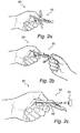
- FIGs. 2a-2c An example of the process for releasing the drill 10 from the package 30 and connecting the drill 10 to a tool holding fixture 80 is illustrated Figs. 2a-2c .
- At least the protecting portion 34 is made from a flexible material thus allowing the user 90 to clamp the cutting portion 14 of the drill 10 by pressing ( Fig. 2a ) the protecting portion 34 and thereby establishing a contact between the protecting portion 34 and the cutting portion 14 of the drill 10.
- the locking portion 36 and the protecting portion 34 are movable relative each other.
- a movement (indicated with a curved arrow in Fig. 2b ) of the locking portion 36 relative the protecting portion 34 results in the release of the tool engaging portion 16 of the drill 10 as illustrated in Figs. 2b-2c .
- the movement between the locking portion 36 and the protecting portion 34 is possible by means of a bendable portion 42 located somewhere between the locking portion 36 and the distal end 32c of the protecting portion 34.
- the user 90 clamps the gripping portion 38 and the movement of the locking portion 36 relative the protecting portion 34 is achieved by a movement of the gripping portion 38 away from the longitudinal axis L. Accordingly, in Figs. 2a-2c , the movement of the locking portion 36 relative the protecting portion 34 is achieved by bending.
- Figs 2a-2c the force needed to overcome the holding force of the drill 10 is dependent on the distance between the position where the user 90 clamps the drill 10 and the locking portion 36, and the distance between the locking portion 36 and the position where the user 90 clamps the gripping portion 38.
- a bendable portion 42 is achievable by means of a bendable portion 42, other alternatives such as a hinge, a mechanical joint or other similar pivoting means are possible.
- the movement is achieved by pivoting the locking portion 36 around an axis that is perpendicular to the longitudinal axis L of the package 30. In the drawing, this is illustrated as a downward movement, i.e. opposite to the opening of the snap lock 37, which is facing upwards.
- Fig 3a-3b illustrates an package 30 according to at least one example embodiment of the invention.
- Fig 3a shows the package 30 in its unfolded state, i.e. prior to the fixation of the drill to the package 30.
- Fig 3b illustrates a state where the package 30 has been folded to enclose the drill (the drill is not shown in Figs 3a-3b ).
- Two grooves 31 a, 31 b are present on both sides of the short distal package portion 32c allowing for the package to be folded.
- the example embodiment shown in Figs. 3a-3b has many similarities to the example embodiments shown in Figs. 1-2 but with some additional features such as lateral sidewall 33a-33c present between the first leg 32a and the second leg 32b of the package 30. Furthermore, the gripping portion 39 and the locking portion 36 are designed a bit differently compared to the example embodiments shown in Figs. 1-2 .
- the lateral sidewalls 33a, 33b extends from the first leg 32a and are linked to each other by a distal sidewall 33c, also extending from the first leg 32, such that a U-shaped sidewall is formed.
- the U-shaped sidewall is designed to enclose the drill.
- a U-shaped connection part 33d extends from the second leg 32b.
- the connection part 33d is designed to interconnect with the lateral sidewalls, 33a-33c, thus allowing the second leg 32b to be held to the first leg 32a, as shown in Fig. 3a .
- the interconnection between the connection part 33d and the sidewalls 33a-33c is achieved by means of a snapping function.
- lateral sidewalls 33a-33c and the connection part 33d may be interconnected by other means than a snapping function.
- the lateral sidewalls 33a-33c and the connection part 33d may adopt other designs than the U-shape form exemplified here.
- release of the drill 10 due to a movement of the locking portion 36 relative the protecting portion 34 is in the example embodiment shown in Figs. 2a-2c possible by that the user 90 fixates the drill 10 by clamping the protecting portion 34.
- the release of the drill 10 may be performed prior to clamping the drill 10. This may be achieved by moving the locking portion 36 relative the protecting portion 34, so that the package 30 itself withholds the drill 10 by for example the first 32a or the second leg 32b of the U-shaped protecting portion 34.
- one or more lateral sidewalls (33a-33c shown in Figs. 3a-3b ), which interconnect the first leg 32a with the second leg 32b are provided in the protecting portion 34.
- the drill 10 may be contained inside the package 30 without being fixated. Connection of the drill 10 to a tool holding fixture 80 is then possible by the before mentioned clamping of the drill 10 by pressing a flexible part of the protecting portion 34.
- a package may contain two or more drills.
- the drills may be arranged in parallel with each other, each one having a tool engaging portion held by a respective individual locking portion.
- the subportions of the protecting portion may be wider compared to the elongated legs illustrated in the drawings.
Abstract


Description
- The present invention relates to a package for a drill, such as a surgical drill, e.g. a dental drill. The invention also relates to an arrangement comprising a drill and such package. Furthermore, the invention relates to a method for releasing a drill from such package. The invention also relates to a method for connecting a drill held in such package to a tool holding fixture.
- Drills, such as dental drills, should be protected from impacts since the sharp edges of the drill are easily impaired. Furthermore, dental drills need to be kept in a sterile environment until shortly before use. The cutting region of the drill (i.e. the bit) is especially associated with high demands of sterility. Therefore there are high demands on the drill's packaging.
- During insertion of the drill into, for example, a tool holding fixture, the handling of the drill's package is important since it is cumbersome to release the drill from the package without touching the drilling bit. Progress in the field of packages for drills has led to the possibility to insert the drill into a tool holding fixture without touching the bit.
-
DE-A-102005022385 discloses an individual packaging case for objects with fracture risk. This packaging case comprises a base with an open, upward-pointing receiving bore, into which the shank of the object with fracture risk is inserted and self-containedly protrudes from the bore. The fragile particle is protected by means of a protective cap. Further, the packaging case is foldable over an axis running perpendicular to the longitudinal axis and due to the folding, the object to be protected becomes at least partly freely accessible. - A problem with this kind of packaging case is that it needs to be very clean in order to prevent contamination of the object since the cutting edges of the drill is not fastened to the package in a contact free manner. Unless the drill is properly arranged in the package, there may be a risk of the drill wobbling and repeatedly impinging against the package during transport and handling of the package. In such case, the drill may be contaminated by particles of the packaging material which may become cut away and subsequently be transferred with the drill into the oral cavity of a patient, which is undesirable.
- A solution to this problem is disclosed in
US2011/0056850 where a package housing for an elongate object is disclosed. This package housing includes a base element having a housing wall. The base element comprises a head part and a holding part connected to each other by a weakening zone, the latter is a predetermined breaking zone. The holding part includes a holding portion which is intended to hold the object in the holding part. The holding portion includes a spacer such that the object can be held in a contact-free manner with respect to the housing wall. - However this type of package housing has a rather complicated construction and the industry is in need of further packaging improvements entailing an easy connection of the drill to a tool holding fixture.
- An object of the invention is therefore to overcome the above problems, and to provide a package for a drill which is easy to handle during the connection of the drill to a tool holding fixture.
- This and other objects, which will become apparent in the following, are accomplished by means of a package, an arrangement and methods defined in the accompanying claims.
- The present invention is based on the insight that a cutting portion of a drill may be held out of contact from the package until the time of installation of the drill into a tool holding fixture, at which time a user may clamp the cutting portion of the drill with the package to hold and guide the drill into the tool holding fixture. In other words, repeated impinging of the drill against the package is avoided while allowing a controlled one-time gripping of the drill, which is not believed to cause the above mentioned cutting-away of packaging material. Compared to the prior art, this results in an easier handling during the installation of the drill into a tool holding fixture, while still maintaining a satisfactory level of sterility and patient safety.
- In particular, the inventor has realized that if while clamping the cutting portion of the drill, release of the drill from its package can easily be accomplished if the part of the package securing a tool engaging portion of the drill, i.e. a locking portion of the package, is moved relative the protecting portion of the package. Hereafter the drill can be inserted into a tool holding fixture in an easy manner and with full control of the user.
- According to at least a first aspect of the invention, a package for a drill is provided. The package comprises
- a protecting portion comprising a first subportion and a second subportion, the protecting portion being arranged to house a cutting portion of said drill in a contact free manner, and
- a locking portion arranged to hold a tool engaging portion of said drill,
- wherein the locking portion and the protecting portion are movable relative each other,
- wherein the drill is releasable from the locking portion by a movement of the locking portion relative the protecting portion, and
- wherein the first and the second subportions of the protecting portion are made in one piece and are arranged to allow the user to clamp the cutting portion of said drill by pressing the first subportion towards the second subportion and thereby establishing a contact between the protecting portion and the cutting portion of said drill.
- When the user fixates the drill by pressing the first and/or the second subportion(s) of the protecting portion an easy connection of the drill to a tool holding fixture is possible, without the need for the user to touch the cutting portion of the drill. The user may fixate the drill after the drill has been released from the locking portion. However, the user may fixate the drill prior to the releasing movement of the locking portion, which is advantageous since the clamping fixation of the cutting portion facilitates the release of the drill from the locking portion when the locking portion is moved relative to the protecting portion.
- It should be understood that the cutting portion is the part of the drill not being the tool engaging portion of the drill. The cutting portion generally comprises the sharp edges of the drill (the bit), which can be located along the longitudinal axis of the drill or perpendicular to the axis of the drill or located in another direction, while the tool engaging portion generally comprises the shank of the drill. Furthermore, the drill and the tool holding fixture are two different objects. The drill is here defined as the object used for creating a bore hole and being in direct contact with the matter cut or pressed away, while the tool holding fixture is the equipment to which the drill is to be connected. The tool holding fixture may be a drilling apparatus used by e.g. a dentist.
- The protecting portion has at least two functions, one being to house the cutting portion of the drill in a contact-free manner, thereby avoiding sharp edges from contact with the package during storage and transport. This ensures that the drill is kept away from possible contaminations. A second function is to provide a portion allowing the user to clamp the drill by pressing the outer surface of that portion. It should be noted that the protecting portion may house only a part of the cutting portion of the drill. However, the protecting portion may also completely house the cutting portion of the drill.
- As mentioned previously, the locking portion and the protecting portion are movable relative each other. Hereby the drill can be released from the locking portion by fixing the drill in the protecting portion and subsequently, or prior to fixing the drill in the protecting portion, establishing a movement of the protecting portion relative the locking portion. This is advantageous since it entails easy handling of the drill upon connection of the drill to a tool holding fixture. In other words, the package can be regarded as having two drill fixating portions. One drill fixating portion would be the locking portion which is intended to initially fixate the drill during storage. The other one would be the protecting portion which is intended to temporarily fixate the drill by manual force while the drill is connected to a tool holding fixture. Thus, the package according to the invention allows for a change from the locking portion's non-manual fixation of the drill to the protecting portion's manual fixation of the drill.
- As mentioned previously, the first subportion is made in one piece with the second subportion of the protecting portion, i.e. they are integral with each other. The protecting portion may, for instance, be made by injection moulding or vacuum forming. According to at least one example embodiment, the second subportion is a continuation of the first subportion, without any intermediate portion there between. According to at least one example embodiment, the first subportion and the second subportion are connected by means of a distal package portion, the distal package portion being a continuation of the first subportion and the second subportion being a continuation of the distal package portion.
- According to at least one example embodiment, the protecting portion is made in one piece with the locking portion. Hereby, the protecting portion and the locking portion may, for instance, be made by injection moulding or vacuum forming. According to at least one example embodiment, the whole package is made in one piece by e.g. injection moulding or vacuum forming.
- According to at least one example embodiment, the package is an inner package adapted to be contained in an outer package. Thus, the inner package may be sterilized together with the drill while the outer surface of the outer package may be non-sterile. The outer package may then also assure sterility by protecting the drill and its inner package from outer contamination.
- According to at least one example embodiment, the movement of the locking portion relative the protecting portion while the cutting portion of the drill is clamped results in the release of the tool engaging portion of the drill from the locking portion. According to at least one example embodiment, the movement of the locking portion, and thus the release of the drill, occurs prior to the clamping of the cutting portion of the drill. This may be achieved by the package itself, for instance, during the movement of the locking portion the drill may become tilted so that the cutting portion abuts the walls of the protecting portion. Hereby a counterforce, similar to when clamping the drill, is exerted on the drill by the walls of the package, thus allowing for the release of the drill with the continued relative movement between the locking portion and the protecting portion.
- According to at least one example embodiment, at least one of the first and the second subportions of the protecting portion is made from a flexible material. According to at least one example embodiment, other parts of the package are made from a flexible material. The flexible material may be plastic, but it may also be other materials, such as rubber, paper or thin metal foil. By having the drill's package at least partly made from a flexible material, the drill may be stored out of contact from the package and then clamped at will. The installation procedure is especially facilitated if the portion of the package protecting the cutting portion of the drill, e.g. the first and the second subportions of the protecting portion, is made from a flexible material. In this case, a user is allowed to fixate the drill by clamping the protecting portion.
- By having the package at least partly made in a flexible material, bending and compressing the package is possible, while a non-flexible part of the package may provide for increased rigidity and stability of the package. For example, two different parts of the package may be made from a flexible material. The first flexible part may be a part of the protecting portion which enables the user to clamp the drill in the before mentioned manner, while the second flexible part may allow for the movement between the protecting portion and the locking portion, e.g. by a bending movement. The remaining parts of the package may be made from a non-flexible material. Hereby, the risk for a part of the package to flex back is reduced. Also, having parts of the package made from a non-flexible material reduces the risk of the package prematurely coming into contact with the sharp edges of the drill.
- It should be understood that the term flexible here implies that a user may bend or flex the parts being flexible. Thus, a package may still be made in one piece, where some portions are made thicker, e.g. so thick that the user cannot bend or flex such portions (i.e. not flexible portions) with his/her fingers while some portions are made thinner, e.g. thin enough for a user to bend or flex such portions (i.e. flexible portions) with his/her fingers. In other words, the package may be made partly flexible.
- Further, by constructing at least a part of the package in a flexible material, such as plastic, a cheap and functional package may be made. Also using plastic material facilitates the manufacturing process since the package may be produced by injection moulding, vacuum forming etc.
- It should be noted that the user may clamp the protecting portion and thereby establish a contact between the package and at least a part of the drill by other means than having the package at least partly made from a flexible material. For instance, the first subportion may be allowed to be moved towards the second subportion by means of a hinge. Hereby the first and the second subportions of the protecting portion may be rigidly constructed.
- According to at least one example embodiment the protecting portion has a U-shaped cross-section around the cutting portion of the drill. The first and second subportions of the protecting portion form the two legs of the U-shape. Suitably, distally of the cutting portion of the drill a space is formed between the drill and the central connecting distal package portion of the "U-shape" of the package.
- According to at least one example embodiment the first and second subportions are formed as elongated legs. According to other example embodiments the first and second subportion may have other shapes, for instance, the shape of a square. Such shapes may be advantageous, for instance, for accommodating several drills arranged in parallel with each other and held by respective locking portions.
- According to at least one example embodiment, the locking portion comprises a snap lock. The use of a snap lock is advantageous since it is possible to integrate the locking means with the remaining package. Hereby also the manufacturing process is facilitated since a snap lock is possible to produce by injection moulding. A snap lock is further advantageous since it may be designed strong enough for holding the drill securely during storage and transport, and yet weak enough to enables the drill to be released using a relatively small force. However, the use of a snap lock does not limit the invention, the drill could be fastened by other means, such as a mechanical lock. For example, the mechanical lock may contain the tool engaging portion of the drill by means of a foldable cap. Unfolding the cap from the engaging portion of the drill may then result in the release of the drill from the package.
- According to at least one example embodiment, the package is adapted such that the movement of the locking portion relative the protecting portion may be achieved by bending the package. Hereby, the relative movement between the locking portion and the protecting portion is carried out in a simple manner. The bending movement is especially suitable for sections of the package made from a flexible material.
- According to at least one example embodiment, the package is adapted such that the relative movement between the locking portion and the protecting portion may be achieved by pivoting the locking portion around an axis that is perpendicular to the longitudinal axis of the package. According to at least one example embodiment, the package is adapted such that the relative movement between the locking portion and the protecting portion may be achieved by pivoting the locking portion around the longitudinal axis of the package. It should be understood that the function of the relative movement between the locking portion and the protecting portion is to release the drill from the locking portion. This could be achieved by any other suitable type of relative movement between the locking portion and the protecting portion.
- According to at least one example embodiment, the package further comprises a gripping portion located adjacent the locking portion. The gripping portion has the advantage that it facilitates handling of the package by allowing the user to hold a specific part of the package. This is advantageous for example when the user removes the package from an outer package and also when the user removes the drill from the package. Hereby, the user can avoid unintentional touching of the drill.
- The word adjacent does here imply that the gripping portion is located in close proximity of the locking portion. According to at least one example embodiment, the gripping portion is located opposite the protecting portion such that the locking portion is located between the gripping portion and the protecting portion. According to at least one example embodiment, the gripping portion is juxtapositioned the locking portion. According to at least one example embodiment, the gripping portion is designed such that it is integrated with the locking portion. According to yet another example embodiment the gripping portion is located between the locking portion and a distal end of the protecting portion.
- According to at least one example embodiment, the gripping portion is designed as a lip. Hereby the user can easily grip the lip by using a thumb and another finger. This type of grip is advantageously when the user removes the inner package from the outer package and also when the user removes the drill from the package.
- According to at least one example embodiment, the package is adapted such that the relative movement between the locking portion and the protecting portion may be achieved by a movement of the gripping portion away from the longitudinal axis of the package. Hereby the drill can be released from the locking portion by for example bending the package.
- According to at least a second aspect of the invention, a method is provided for releasing a drill from a package comprising a protecting portion housing a cutting portion of the drill in a contact free manner and a locking portion holding a tool engaging portion of the drill,
the method comprising the steps of
clamping the drill by pressing the protecting portion;
releasing the drill from the locking portion by moving the locking portion relative the protecting portion while maintaining the clamping of the drill. - Effects and features of this second aspect of the present invention are largely analogous to those described above in connection with the first aspect. For instance, the package may partly be made in a flexible material and/or be made in one piece.
- According to at least one example embodiment, a method is provided wherein the movement of the locking portion relative the protecting portion is achieved by bending the package.
- According to at least one example embodiment, a method is provided wherein the relative movement between the locking portion and the protecting portion is achieved by pivoting the locking portion around an axis that is perpendicular to the longitudinal axis of the package.
- According to at least one example embodiment, a method is provided where wherein the package further comprises a gripping portion located adjacent to the locking portion. The relative movement between the locking portion and the protecting portion may thus be achieved by a movement of the gripping portion away from the longitudinal axis of the package.
- According to at least a third aspect of the invention a method is provided for connecting to a tool holding fixture a drill held in a package comprising a protecting portion housing a cutting portion of the drill in a contact free manner and a locking portion holding a tool engaging portion of the drill,
the method comprising the steps of
releasing the drill from the locking portion by moving the locking portion relative the protecting portion, and
clamping the drill by pressing the protecting portion wherein the clamping is performed prior, after or during the step of releasing the drill, and
connecting, while maintaining the clamping of the drill, the tool engaging portion of the drill to the tool holding fixture. - Effects and features of this third aspect of the present invention are largely analogous to those described above in connection with the first and second aspects. For instance, the package may partly be made in a flexible material and/or be made in one piece.
- According to at least a fourth aspect of the invention an arrangement comprising a package according to the first aspect and a drill is provided. In the arrangement the protecting portion of the package houses a cutting portion of the drill in a contact free manner, and
wherein the locking portion of the package holds a tool engaging portion of the drill, and
wherein the locking portion and the protecting portion are movable relative each other, and
wherein the drill is releasable from the locking portion by a movement of the locking portion relative the protecting portion, and
wherein the protecting portion comprises a first subportion and a second subportion arranged to allow the user to clamp the tool engaging portion of the drill by pressing the first subportion towards the second subportion and thereby establishing a contact between the protecting portion and the cutting portion of the drill. - According to at least one example embodiment, the movement of the locking portion relative the protecting portion while the cutting portion of the drill is clamped results in the release of the tool engaging portion of the drill from the locking portion. According to at least one example embodiment, the movement of the locking portion, and thus the release of the drill, occurs prior to the clamping of the cutting portion of the drill. This may be achieved by that the package itself withholds the drill by for example the walls of the protecting portion. Hereby a counterforce, similar to when clamping the drill, is exerted on the drill by the walls of the package, thus allowing for the release of the drill with the relative movement between the locking portion and the protecting portion.
- Effects and features of this fourth aspect of the present invention are largely analogous to those described above in connection with the first, second and third aspects. For instance, the package may partly be made in a flexible material and/or be made in one piece.
-
-
Fig. 1 illustrates an arrangement comprising a drill and a package according to at least one example embodiment of the invention. -
Figs. 2a-2c schematically illustrates a procedure for releasing a drill from its package and connecting the drill to a tool holding fixture according to at least one example embodiment of the invention. -
Figs 3a-3b schematically illustrates a package according to at least one example embodiment of the invention. -
Fig. 1 illustrates an arrangement comprising adrill 10 and apackage 30 according to at least one example embodiment of the invention. - The
package 30 inFig. 1 comprises a protectingportion 34, a lockingportion 36 and a grippingportion 38, wherein thepackage 30 has a geometrical longitudinal axis L. In the illustrated example, thedrill 10 is secured to the lockingportion 36 of thepackage 30 in such manner that the its geometrical longitudinal axis I coincides or is parallel with the longitudinal axis L of thepackage 30. - The protecting
portion 34 is arranged to house a cuttingportion 14 of thedrill 10 in a contact free manner. This is illustrated by a gap Ga located along the longitudinal axis L, and a gap Gb located radially of the longitudinal axis L, both gaps Ga, Gb being defined by the protectingportion 34 and the cuttingportion 14 of thedrill 10. The protectingportion 34 is substantially U-shaped. The U-shape forms part of first and second subportions in the form of an elongatedfirst leg 32a and an elongatedsecond leg 32b of thepackage 30, whichlegs distal package portion 32c. In the illustrated example embodiment, the first subportion orleg 32a is longer than the second subportion orleg 32b and provides a base from which the lockingportion 36 projects. Also, the end of thefirst leg 32a may be provided with acurve 48 to form the grippingportion 38. Thefirst leg 32a, thesecond leg 32b and the linkingdistal portion 32c may all be flexible. Alternatively, it would be conceivable to only have one leg flexible (e.g. thefirst leg 32a) and the other rigid (e.g. thesecond leg 32b). Although, the illustratedpackage 30 is open laterally, in other embodiments it would be conceivable to have one or more lateral sidewalls (33a-33c shown infig 3a-3b ), which interconnect thefirst leg 32a with thesecond leg 32b similarly to thedistal package portion 32c, thus further enclosing/concealing the cuttingportion 14 of thedrill 10. Furthermore, such lateral sidewalls do not necessarily have to interconnect thelegs second leg 32b downwards towards but not all the way to thefirst leg 32a. - The locking
portion 36 is arranged to hold thetool engaging portion 16 of thedrill 10. In the illustrated example, the lockingportion 36 comprises asnap lock 37. Although, the lockingportion 36 inFigs. 1-2 comprises asnap lock 37, locking by other means are possible. - The gripping
portion 38 is located adjacent the lockingportion 36 and may be constructed in various manners. The grippingportion 38 facilitates the handling of thepackage 30, for example when removing thepackage 30 from an outer package (not shown) and when installing thedrill 10 into a tool holding fixture 80 (shown inFig. 2c ). In the illustrated example, the grippingportion 38 is designed as a lip. This is advantageous since theuser 90 may perform the gripping (indicated with the arrows inFig. 2a ) by using a thumb and another finger (e.g. the indexing finger). In one example embodiment the grippingportion 38 may adjoin the lockingportion 36. - When inserting the
drill 10 into thepackage 30, theshaft 26 of thedrill 10 is secured to the lockingportion 36. In the example embodiments inFig. 1 , this is achieved by that thesnap lock 37 in the lockingportion 36 first deflects and after theshaft 26 has been placed correctly, elastically springs back. Hereby, a stable and secure locking of thedrill 10 is achieved. As mentioned before an outer package may cover thedrill 10 and itspackage 30. - An example of the process for releasing the
drill 10 from thepackage 30 and connecting thedrill 10 to atool holding fixture 80 is illustratedFigs. 2a-2c . At least the protectingportion 34 is made from a flexible material thus allowing theuser 90 to clamp the cuttingportion 14 of thedrill 10 by pressing (Fig. 2a ) the protectingportion 34 and thereby establishing a contact between the protectingportion 34 and the cuttingportion 14 of thedrill 10. - As can be seen in
Figs. 2b-2c , the lockingportion 36 and the protectingportion 34 are movable relative each other. When theuser 90 clamps the flexible protectingportion 34, and thereby establishes a contact between the protectingportion 34 and the cuttingportion 14 of thedrill 10, a movement (indicated with a curved arrow inFig. 2b ) of the lockingportion 36 relative the protectingportion 34 results in the release of thetool engaging portion 16 of thedrill 10 as illustrated inFigs. 2b-2c . - In the examples illustrated in
Figs. 2a-2c , the movement between the lockingportion 36 and the protectingportion 34 is possible by means of abendable portion 42 located somewhere between the lockingportion 36 and thedistal end 32c of the protectingportion 34. InFigs. 2a-2c theuser 90 clamps the grippingportion 38 and the movement of the lockingportion 36 relative the protectingportion 34 is achieved by a movement of the grippingportion 38 away from the longitudinal axis L. Accordingly, inFigs. 2a-2c , the movement of the lockingportion 36 relative the protectingportion 34 is achieved by bending. - In
Figs 2a-2c the force needed to overcome the holding force of thedrill 10 is dependent on the distance between the position where theuser 90 clamps thedrill 10 and the lockingportion 36, and the distance between the lockingportion 36 and the position where theuser 90 clamps the grippingportion 38. - Although, the movement in
Fig. 2b is achievable by means of abendable portion 42, other alternatives such as a hinge, a mechanical joint or other similar pivoting means are possible. - As seen in
Fig. 2b , the movement is achieved by pivoting the lockingportion 36 around an axis that is perpendicular to the longitudinal axis L of thepackage 30. In the drawing, this is illustrated as a downward movement, i.e. opposite to the opening of thesnap lock 37, which is facing upwards. - The procedure of releasing the
drill 10 can in other words be explained with reference to the fixation of thedrill 10 by the three following states: - State1: The
drill 10 is fixed in a first fixing position by the lockingportion 36, (the cuttingportion 14 of thedrill 10 is housed inside the protecting portion 34) as illustrated inFig. 1 . - State 2: The
drill 10 is fixed in a first fixing position by the lockingportion 36, (the cuttingportion 14 of thedrill 10 is housed inside the protecting portion 34), and thedrill 10 is fixed in a second fixing position by the protecting portion 34 (theuser 90 clamps the protecting portion 34) as illustrated inFigs 2a-2b . - State 3: The
drill 10 is released from the first fixing position by a movement of the lockingportion 36 relative the protectingportion 34 while the second fixing position remains unchanged, thus thedrill 10 is (only) fixed in the second fixing position by the protecting portion 34 (and is ready to be installed into a tool holding fixture 80) as illustrated inFig. 2c . -
Fig 3a-3b illustrates anpackage 30 according to at least one example embodiment of the invention.Fig 3a shows thepackage 30 in its unfolded state, i.e. prior to the fixation of the drill to thepackage 30.Fig 3b illustrates a state where thepackage 30 has been folded to enclose the drill (the drill is not shown inFigs 3a-3b ). Twogrooves distal package portion 32c allowing for the package to be folded. - The example embodiment shown in
Figs. 3a-3b has many similarities to the example embodiments shown inFigs. 1-2 but with some additional features such aslateral sidewall 33a-33c present between thefirst leg 32a and thesecond leg 32b of thepackage 30. Furthermore, the grippingportion 39 and the lockingportion 36 are designed a bit differently compared to the example embodiments shown inFigs. 1-2 . - In
Fig 3a thelateral sidewalls first leg 32a and are linked to each other by adistal sidewall 33c, also extending from the first leg 32, such that a U-shaped sidewall is formed. The U-shaped sidewall is designed to enclose the drill. Furthermore, inFigs. 3a-3b aU-shaped connection part 33d extends from thesecond leg 32b. Theconnection part 33d is designed to interconnect with the lateral sidewalls, 33a-33c, thus allowing thesecond leg 32b to be held to thefirst leg 32a, as shown inFig. 3a . In the illustrated example, the interconnection between theconnection part 33d and thesidewalls 33a-33c is achieved by means of a snapping function. Of course thelateral sidewalls 33a-33c and theconnection part 33d may be interconnected by other means than a snapping function. Furthermore, thelateral sidewalls 33a-33c and theconnection part 33d may adopt other designs than the U-shape form exemplified here. - Release of the
drill 10 due to a movement of the lockingportion 36 relative the protectingportion 34 is in the example embodiment shown inFigs. 2a-2c possible by that theuser 90 fixates thedrill 10 by clamping the protectingportion 34. In an alternative embodiment, the release of thedrill 10 may be performed prior to clamping thedrill 10. This may be achieved by moving the lockingportion 36 relative the protectingportion 34, so that thepackage 30 itself withholds thedrill 10 by for example the first 32a or thesecond leg 32b of the U-shaped protectingportion 34. Preferably, one or more lateral sidewalls (33a-33c shown inFigs. 3a-3b ), which interconnect thefirst leg 32a with thesecond leg 32b are provided in the protectingportion 34. Hereby, after thedrill 10 is released from the lockingportion 36, thedrill 10 may be contained inside thepackage 30 without being fixated. Connection of thedrill 10 to atool holding fixture 80 is then possible by the before mentioned clamping of thedrill 10 by pressing a flexible part of the protectingportion 34. - The person skilled in the art realizes that the present invention by no means is limited to the embodiments described above. For instance, although the drawings have only illustrated packages containing a single drill, according to other example embodiments, a package may contain two or more drills. For instance, the drills may be arranged in parallel with each other, each one having a tool engaging portion held by a respective individual locking portion. For such a multi-drill package, the subportions of the protecting portion may be wider compared to the elongated legs illustrated in the drawings.
Claims (17)
- A package for a drill, comprising
a protecting portion comprising a first subportion and a second subportion, the protecting portion being arranged to house a cutting portion of said drill in a contact free manner, and
a locking portion arranged to hold a tool engaging portion of said drill, wherein the locking portion and the protecting portion are movable relative each other,
wherein the drill is releasable from the locking portion by a movement of the locking portion relative the protecting portion, and
wherein the first and the second subportions of the protecting portion are made in one piece and are arranged to allow the user to clamp the cutting portion of said drill by pressing the first subportion towards the second subportion and thereby establishing a contact between the protecting portion and the cutting portion of said drill. - A package according to claim 1, wherein the protecting portion is made in one piece with the locking portion.
- A package according to any one of claims 1-2, wherein the package is an inner package adapted to be contained in an outer package.
- A package according to any one of claims 1-3, wherein the movement of the locking portion relative the protecting portion while the cutting portion of the drill is clamped results in the release of the tool engaging portion of the drill from the locking portion.
- A package according to any one of claims 1-4, wherein at least one of the subportions of the protecting portion is made from a flexible material.
- A package according to any one of the preceding claims, wherein the locking portion comprises a snap lock.
- A package according to any one of the preceding claims, wherein the package is adapted such that the movement of the locking portion relative the protecting portion may be achieved by bending.
- A package according to any one of the preceding claims, wherein the package is adapted such that the relative movement between the locking portion and the protecting portion may be achieved by pivoting the locking portion around an axis that is perpendicular to a longitudinal axis of the package.
- A package according to any of the preceding claims, further comprising a gripping portion located adjacent the locking portion.
- A package according to claim 9, wherein the package is adapted such that the relative movement between the locking portion and the protecting portion may be achieved by a movement of the gripping portion away from the longitudinal axis of the package.
- A method for releasing a drill from a package comprising
a protecting portion housing a cutting portion of said drill in a contact free manner and a locking portion holding a tool engaging portion of said drill,
said method comprising the steps of
clamping the drill by pressing the protecting portion;
releasing the drill from the locking portion by moving the locking portion relative the protecting portion while maintaining the clamping of the drill. - A method according to claim 11, wherein the movement of the locking portion relative the protecting portion is achieved by bending the package.
- A method according to any one of claims 11 or 12, wherein the relative movement between the locking portion and the protecting portion is achieved by pivoting the locking portion around an axis that is perpendicular to a longitudinal axis of the package.
- A method according to any one of claims 11-13, wherein the package further comprises a gripping portion located adjacent to the locking portion and wherein the relative movement between the locking portion and the protecting portion is achieved by movement of the gripping portion away from the longitudinal axis of the package.
- A method for connecting to a tool holding fixture a drill held in a package comprising a protecting portion housing a cutting portion of said drill in a contact free manner and a locking portion holding a tool engaging portion of said drill,
said method comprising the steps of
releasing the drill from the locking portion by moving the locking portion relative the protecting portion, and
clamping the drill by pressing the protecting portion wherein said clamping is performed prior, after or during said step of releasing the drill, and
connecting, while maintaining the clamping of the drill, the tool engaging portion of the drill to the tool holding fixture. - An arrangement comprising a package according to any one of claims 1-10 and a drill,
wherein said protecting portion of the package houses a cutting portion of said drill in a contact free manner, and
wherein said locking portion of the package holds a tool engaging portion of said drill, and
wherein the locking portion and the protecting portion are movable relative each other, and
wherein the drill is releasable from the locking portion by a movement of the locking portion relative the protecting portion, and
wherein the protecting portion comprises a first subportion and a second subportion arranged to allow the user to clamp the tool engaging portion of said drill by pressing the first subportion towards the second subportion and thereby establishing a contact between the protecting portion and the cutting portion of said drill. - An arrangement according to claim 16, wherein the movement of the locking portion relative the protecting portion while the cutting portion of the drill is clamped results in the release of the tool engaging portion of the drill from the locking portion.
Priority Applications (8)
| Application Number | Priority Date | Filing Date | Title |
|---|---|---|---|
| EP12167150.7A EP2662312B1 (en) | 2012-05-08 | 2012-05-08 | A package for drills, a method and an arrangement therefor |
| ES12167150.7T ES2526883T3 (en) | 2012-05-08 | 2012-05-08 | Package for drill bits, associated method and arrangement |
| US13/862,643 US20130299371A1 (en) | 2012-05-08 | 2013-04-15 | Package for drills, a method and an arrangement therefore |
| CN201380023127.9A CN104271467B (en) | 2012-05-08 | 2013-04-16 | For packaging, the method and apparatus thus of drill bit |
| RU2014149216A RU2616550C2 (en) | 2012-05-08 | 2013-04-16 | Packaging for drill, method and its design |
| JP2015510706A JP6159394B2 (en) | 2012-05-08 | 2013-04-16 | Package for drill, method and arrangement therefor |
| PCT/EP2013/057857 WO2013167353A1 (en) | 2012-05-08 | 2013-04-16 | A package for drills, a method and an arrangement therefore |
| US18/122,167 US20230219741A1 (en) | 2012-05-08 | 2023-03-16 | Package for drills, a method and an arrangement therefore |
Applications Claiming Priority (1)
| Application Number | Priority Date | Filing Date | Title |
|---|---|---|---|
| EP12167150.7A EP2662312B1 (en) | 2012-05-08 | 2012-05-08 | A package for drills, a method and an arrangement therefor |
Publications (2)
| Publication Number | Publication Date |
|---|---|
| EP2662312A1 true EP2662312A1 (en) | 2013-11-13 |
| EP2662312B1 EP2662312B1 (en) | 2014-10-08 |
Family
ID=46146650
Family Applications (1)
| Application Number | Title | Priority Date | Filing Date |
|---|---|---|---|
| EP12167150.7A Active EP2662312B1 (en) | 2012-05-08 | 2012-05-08 | A package for drills, a method and an arrangement therefor |
Country Status (7)
| Country | Link |
|---|---|
| US (2) | US20130299371A1 (en) |
| EP (1) | EP2662312B1 (en) |
| JP (1) | JP6159394B2 (en) |
| CN (1) | CN104271467B (en) |
| ES (1) | ES2526883T3 (en) |
| RU (1) | RU2616550C2 (en) |
| WO (1) | WO2013167353A1 (en) |
Cited By (3)
| Publication number | Priority date | Publication date | Assignee | Title |
|---|---|---|---|---|
| DE102015002214A1 (en) * | 2015-02-20 | 2016-08-25 | Rose Plastic Ag | Protective packaging with assembly and disassembly function |
| CN112692800A (en) * | 2020-12-17 | 2021-04-23 | 东台升华工具有限公司 | Drill bit drilling and milling system convenient to maintain and manage |
| EP4356872A1 (en) * | 2022-10-21 | 2024-04-24 | Ferton Holding S.A. | Tool for transferring a dental tool tip between an assembled and a disassembled state and method for removing a dental tool tip from a dental instrument |
Families Citing this family (12)
| Publication number | Priority date | Publication date | Assignee | Title |
|---|---|---|---|---|
| US9439658B2 (en) * | 2013-05-14 | 2016-09-13 | SpineDriver, LLC | Drill bit package assembly |
| US11633270B2 (en) * | 2015-06-12 | 2023-04-25 | Rtrs Investment, Llc | Systems and methods for sterile delivery of prostheses |
| WO2017210640A1 (en) | 2016-06-03 | 2017-12-07 | Lutron Electronics Co., Inc. | Battery-powered retrofit remote control device |
| US9827063B1 (en) * | 2016-07-06 | 2017-11-28 | Medtronic Vascular, Inc. | Hybrid sealed tray for long catheter delivery systems |
| US10004567B2 (en) * | 2016-09-15 | 2018-06-26 | Ethicon, Inc. | Sterile packaging systems for medical devices |
| WO2018191396A1 (en) * | 2017-04-12 | 2018-10-18 | Mako Surgical Corp. | Packaging systems and methods for mounting a tool on a surgical device |
| US11690680B2 (en) | 2019-03-19 | 2023-07-04 | Mako Surgical Corp. | Trackable protective packaging for tools and methods for calibrating tool installation using the same |
| USD943765S1 (en) | 2019-03-26 | 2022-02-15 | Practicon, Inc. | Bur holder |
| US11246679B2 (en) * | 2019-03-26 | 2022-02-15 | Practicon, Inc. | Device for holding medical instruments and method of using same |
| US11395711B2 (en) | 2019-06-05 | 2022-07-26 | Stryker European Operations Limited | Packaging systems and methods for mounting a tool on a surgical device using the same |
| RU2716613C1 (en) * | 2019-09-06 | 2020-03-13 | Общество с ограниченной ответственностью "Газпром трансгаз Екатеринбург" | Cartridge for organized storage of drills |
| CN113491549A (en) * | 2020-04-03 | 2021-10-12 | 江苏风和医疗器材股份有限公司 | Assembly for a surgical instrument and surgical kit |
Citations (7)
| Publication number | Priority date | Publication date | Assignee | Title |
|---|---|---|---|---|
| US3010569A (en) * | 1958-04-30 | 1961-11-28 | Boonton Molding Company | Protective case for medical thermometer |
| DE19715030A1 (en) * | 1997-04-11 | 1998-10-15 | Rose Plastic Gmbh | Packaging container for elongated objects |
| DE10146905A1 (en) * | 2001-09-24 | 2003-07-31 | Brasseler Gmbh & Co Kg Geb | Holder package for a surgical instrument, e.g. a drill bit for implants, has a holder for the tool shaft and a removable cap, held together in a tight fit to keep the instrument sterile until required for use |
| DE102005022385A1 (en) | 2005-05-14 | 2006-11-16 | Rösler, Peter | Individual packing for objects at risk of breakage is bendable around axis which extends transversely to longitudinal axis, and, during bending, the object being protected becomes at least partially freely accessible |
| DE102007005515B3 (en) * | 2007-02-03 | 2008-08-07 | Rösler, Peter | Single packaging for precision tools |
| US20110056850A1 (en) | 2009-09-04 | 2011-03-10 | Straumann Holding Ag | Package housing for an elongate object |
| DE202011105720U1 (en) * | 2011-09-16 | 2011-11-23 | Rose Plastic Ag | Packaging container with clamp for elongated objects |
Family Cites Families (4)
| Publication number | Priority date | Publication date | Assignee | Title |
|---|---|---|---|---|
| CN2275433Y (en) * | 1996-11-25 | 1998-03-04 | 林志声 | Box for sorting dental therapeutic apparatus |
| US6923327B1 (en) * | 2002-10-17 | 2005-08-02 | Jeremy Cohen | Injection molded container |
| US7789239B2 (en) * | 2006-12-11 | 2010-09-07 | Don Juliano | Insert trays for packages, packages including such trays, and methods for packaging articles of manufacture |
| CN202029122U (en) * | 2011-01-27 | 2011-11-09 | 上海昆杰五金工具有限公司 | Lining plate |
-
2012
- 2012-05-08 EP EP12167150.7A patent/EP2662312B1/en active Active
- 2012-05-08 ES ES12167150.7T patent/ES2526883T3/en active Active
-
2013
- 2013-04-15 US US13/862,643 patent/US20130299371A1/en not_active Abandoned
- 2013-04-16 RU RU2014149216A patent/RU2616550C2/en active IP Right Revival
- 2013-04-16 JP JP2015510706A patent/JP6159394B2/en active Active
- 2013-04-16 WO PCT/EP2013/057857 patent/WO2013167353A1/en active Application Filing
- 2013-04-16 CN CN201380023127.9A patent/CN104271467B/en active Active
-
2023
- 2023-03-16 US US18/122,167 patent/US20230219741A1/en active Pending
Patent Citations (7)
| Publication number | Priority date | Publication date | Assignee | Title |
|---|---|---|---|---|
| US3010569A (en) * | 1958-04-30 | 1961-11-28 | Boonton Molding Company | Protective case for medical thermometer |
| DE19715030A1 (en) * | 1997-04-11 | 1998-10-15 | Rose Plastic Gmbh | Packaging container for elongated objects |
| DE10146905A1 (en) * | 2001-09-24 | 2003-07-31 | Brasseler Gmbh & Co Kg Geb | Holder package for a surgical instrument, e.g. a drill bit for implants, has a holder for the tool shaft and a removable cap, held together in a tight fit to keep the instrument sterile until required for use |
| DE102005022385A1 (en) | 2005-05-14 | 2006-11-16 | Rösler, Peter | Individual packing for objects at risk of breakage is bendable around axis which extends transversely to longitudinal axis, and, during bending, the object being protected becomes at least partially freely accessible |
| DE102007005515B3 (en) * | 2007-02-03 | 2008-08-07 | Rösler, Peter | Single packaging for precision tools |
| US20110056850A1 (en) | 2009-09-04 | 2011-03-10 | Straumann Holding Ag | Package housing for an elongate object |
| DE202011105720U1 (en) * | 2011-09-16 | 2011-11-23 | Rose Plastic Ag | Packaging container with clamp for elongated objects |
Cited By (5)
| Publication number | Priority date | Publication date | Assignee | Title |
|---|---|---|---|---|
| DE102015002214A1 (en) * | 2015-02-20 | 2016-08-25 | Rose Plastic Ag | Protective packaging with assembly and disassembly function |
| DE102015002214B4 (en) * | 2015-02-20 | 2021-06-10 | Rose Plastic Ag | Protective packaging with assembly and disassembly function |
| CN112692800A (en) * | 2020-12-17 | 2021-04-23 | 东台升华工具有限公司 | Drill bit drilling and milling system convenient to maintain and manage |
| CN112692800B (en) * | 2020-12-17 | 2023-01-10 | 东台升华工具有限公司 | Drill bit drilling and milling system convenient to maintain and manage |
| EP4356872A1 (en) * | 2022-10-21 | 2024-04-24 | Ferton Holding S.A. | Tool for transferring a dental tool tip between an assembled and a disassembled state and method for removing a dental tool tip from a dental instrument |
Also Published As
| Publication number | Publication date |
|---|---|
| RU2616550C2 (en) | 2017-04-17 |
| JP6159394B2 (en) | 2017-07-05 |
| ES2526883T3 (en) | 2015-01-16 |
| RU2014149216A (en) | 2016-06-27 |
| WO2013167353A1 (en) | 2013-11-14 |
| US20130299371A1 (en) | 2013-11-14 |
| CN104271467B (en) | 2016-04-13 |
| JP2015517333A (en) | 2015-06-22 |
| EP2662312B1 (en) | 2014-10-08 |
| CN104271467A (en) | 2015-01-07 |
| US20230219741A1 (en) | 2023-07-13 |
Similar Documents
| Publication | Publication Date | Title |
|---|---|---|
| US20230219741A1 (en) | Package for drills, a method and an arrangement therefore | |
| US20190315563A1 (en) | Package for drills, a method and an arrangement therefore | |
| JP5511530B2 (en) | Intraocular lens insertion device | |
| US6277132B1 (en) | Needle inserter with a needle protection device | |
| KR101491879B1 (en) | Dentition correcting device, and method for mounting/demounting dentition correcting cap | |
| US9597092B2 (en) | Mechanized surgical equipment comprising an instrument and an instrument holder, corresponding packaging and instrument holder | |
| US10716588B2 (en) | Surgical instrument | |
| EA014264B1 (en) | Cap for injection device | |
| JP4528767B2 (en) | Dissecting blade cutter | |
| WO2018111575A1 (en) | Quick release coupler | |
| EP2682070B1 (en) | Passing tray surgical instruments | |
| AU2010201316B2 (en) | Packaging for surgical blade tips | |
| WO2016054501A1 (en) | Sharps blade applicator and storage device | |
| US20240081957A1 (en) | Dental implant | |
| US9101435B2 (en) | Packaging device for a dental implant | |
| US11653992B2 (en) | Packaging having a holding device for holding a medical tool | |
| KR101260914B1 (en) | Package for dental implant | |
| JP4897241B2 (en) | Packaging container | |
| EP1911411B1 (en) | Medical needle puller | |
| JP4349128B2 (en) | Infusion container fixture | |
| KR200490668Y1 (en) | Case for medical screw | |
| JP3138092U (en) | 鍼 and 鍼 pipe packaging structure | |
| AU2004231277B2 (en) | Scalpel blade remover | |
| WO2020046680A1 (en) | Surgical tool attachment devices, systems, and methods |
Legal Events
| Date | Code | Title | Description |
|---|---|---|---|
| PUAI | Public reference made under article 153(3) epc to a published international application that has entered the european phase |
Free format text: ORIGINAL CODE: 0009012 |
|
| AK | Designated contracting states |
Kind code of ref document: A1 Designated state(s): AL AT BE BG CH CY CZ DE DK EE ES FI FR GB GR HR HU IE IS IT LI LT LU LV MC MK MT NL NO PL PT RO RS SE SI SK SM TR |
|
| AX | Request for extension of the european patent |
Extension state: BA ME |
|
| 17P | Request for examination filed |
Effective date: 20140310 |
|
| RBV | Designated contracting states (corrected) |
Designated state(s): AL AT BE BG CH CY CZ DE DK EE ES FI FR GB GR HR HU IE IS IT LI LT LU LV MC MK MT NL NO PL PT RO RS SE SI SK SM TR |
|
| GRAP | Despatch of communication of intention to grant a patent |
Free format text: ORIGINAL CODE: EPIDOSNIGR1 |
|
| RIC1 | Information provided on ipc code assigned before grant |
Ipc: B65D 85/24 20060101AFI20140515BHEP Ipc: A61C 19/02 20060101ALI20140515BHEP Ipc: A61B 19/02 20060101ALI20140515BHEP Ipc: B65D 25/10 20060101ALN20140515BHEP Ipc: B25H 3/00 20060101ALN20140515BHEP Ipc: A61C 3/04 20060101ALN20140515BHEP |
|
| INTG | Intention to grant announced |
Effective date: 20140612 |
|
| RIN1 | Information on inventor provided before grant (corrected) |
Inventor name: JOHANSSON, HENRIK |
|
| GRAS | Grant fee paid |
Free format text: ORIGINAL CODE: EPIDOSNIGR3 |
|
| GRAA | (expected) grant |
Free format text: ORIGINAL CODE: 0009210 |
|
| AK | Designated contracting states |
Kind code of ref document: B1 Designated state(s): AL AT BE BG CH CY CZ DE DK EE ES FI FR GB GR HR HU IE IS IT LI LT LU LV MC MK MT NL NO PL PT RO RS SE SI SK SM TR |
|
| REG | Reference to a national code |
Ref country code: GB Ref legal event code: FG4D |
|
| REG | Reference to a national code |
Ref country code: CH Ref legal event code: EP Ref country code: AT Ref legal event code: REF Ref document number: 690439 Country of ref document: AT Kind code of ref document: T Effective date: 20141015 |
|
| REG | Reference to a national code |
Ref country code: IE Ref legal event code: FG4D |
|
| REG | Reference to a national code |
Ref country code: DE Ref legal event code: R096 Ref document number: 602012003301 Country of ref document: DE Effective date: 20141120 |
|
| REG | Reference to a national code |
Ref country code: CH Ref legal event code: NV Representative=s name: FIAMMENGHI-FIAMMENGHI, CH |
|
| REG | Reference to a national code |
Ref country code: ES Ref legal event code: FG2A Ref document number: 2526883 Country of ref document: ES Kind code of ref document: T3 Effective date: 20150116 |
|
| REG | Reference to a national code |
Ref country code: NL Ref legal event code: VDEP Effective date: 20141008 |
|
| REG | Reference to a national code |
Ref country code: AT Ref legal event code: MK05 Ref document number: 690439 Country of ref document: AT Kind code of ref document: T Effective date: 20141008 |
|
| REG | Reference to a national code |
Ref country code: LT Ref legal event code: MG4D |
|
| PG25 | Lapsed in a contracting state [announced via postgrant information from national office to epo] |
Ref country code: NL Free format text: LAPSE BECAUSE OF FAILURE TO SUBMIT A TRANSLATION OF THE DESCRIPTION OR TO PAY THE FEE WITHIN THE PRESCRIBED TIME-LIMIT Effective date: 20141008 |
|
| PG25 | Lapsed in a contracting state [announced via postgrant information from national office to epo] |
Ref country code: LT Free format text: LAPSE BECAUSE OF FAILURE TO SUBMIT A TRANSLATION OF THE DESCRIPTION OR TO PAY THE FEE WITHIN THE PRESCRIBED TIME-LIMIT Effective date: 20141008 Ref country code: IS Free format text: LAPSE BECAUSE OF FAILURE TO SUBMIT A TRANSLATION OF THE DESCRIPTION OR TO PAY THE FEE WITHIN THE PRESCRIBED TIME-LIMIT Effective date: 20150208 Ref country code: NO Free format text: LAPSE BECAUSE OF FAILURE TO SUBMIT A TRANSLATION OF THE DESCRIPTION OR TO PAY THE FEE WITHIN THE PRESCRIBED TIME-LIMIT Effective date: 20150108 Ref country code: FI Free format text: LAPSE BECAUSE OF FAILURE TO SUBMIT A TRANSLATION OF THE DESCRIPTION OR TO PAY THE FEE WITHIN THE PRESCRIBED TIME-LIMIT Effective date: 20141008 Ref country code: PT Free format text: LAPSE BECAUSE OF FAILURE TO SUBMIT A TRANSLATION OF THE DESCRIPTION OR TO PAY THE FEE WITHIN THE PRESCRIBED TIME-LIMIT Effective date: 20150209 |
|
| PG25 | Lapsed in a contracting state [announced via postgrant information from national office to epo] |
Ref country code: RS Free format text: LAPSE BECAUSE OF FAILURE TO SUBMIT A TRANSLATION OF THE DESCRIPTION OR TO PAY THE FEE WITHIN THE PRESCRIBED TIME-LIMIT Effective date: 20141008 Ref country code: CY Free format text: LAPSE BECAUSE OF FAILURE TO SUBMIT A TRANSLATION OF THE DESCRIPTION OR TO PAY THE FEE WITHIN THE PRESCRIBED TIME-LIMIT Effective date: 20141008 Ref country code: AT Free format text: LAPSE BECAUSE OF FAILURE TO SUBMIT A TRANSLATION OF THE DESCRIPTION OR TO PAY THE FEE WITHIN THE PRESCRIBED TIME-LIMIT Effective date: 20141008 Ref country code: PL Free format text: LAPSE BECAUSE OF FAILURE TO SUBMIT A TRANSLATION OF THE DESCRIPTION OR TO PAY THE FEE WITHIN THE PRESCRIBED TIME-LIMIT Effective date: 20141008 Ref country code: LV Free format text: LAPSE BECAUSE OF FAILURE TO SUBMIT A TRANSLATION OF THE DESCRIPTION OR TO PAY THE FEE WITHIN THE PRESCRIBED TIME-LIMIT Effective date: 20141008 Ref country code: GR Free format text: LAPSE BECAUSE OF FAILURE TO SUBMIT A TRANSLATION OF THE DESCRIPTION OR TO PAY THE FEE WITHIN THE PRESCRIBED TIME-LIMIT Effective date: 20150109 Ref country code: SE Free format text: LAPSE BECAUSE OF FAILURE TO SUBMIT A TRANSLATION OF THE DESCRIPTION OR TO PAY THE FEE WITHIN THE PRESCRIBED TIME-LIMIT Effective date: 20141008 Ref country code: HR Free format text: LAPSE BECAUSE OF FAILURE TO SUBMIT A TRANSLATION OF THE DESCRIPTION OR TO PAY THE FEE WITHIN THE PRESCRIBED TIME-LIMIT Effective date: 20141008 |
|
| REG | Reference to a national code |
Ref country code: DE Ref legal event code: R097 Ref document number: 602012003301 Country of ref document: DE |
|
| PG25 | Lapsed in a contracting state [announced via postgrant information from national office to epo] |
Ref country code: DK Free format text: LAPSE BECAUSE OF FAILURE TO SUBMIT A TRANSLATION OF THE DESCRIPTION OR TO PAY THE FEE WITHIN THE PRESCRIBED TIME-LIMIT Effective date: 20141008 Ref country code: CZ Free format text: LAPSE BECAUSE OF FAILURE TO SUBMIT A TRANSLATION OF THE DESCRIPTION OR TO PAY THE FEE WITHIN THE PRESCRIBED TIME-LIMIT Effective date: 20141008 Ref country code: RO Free format text: LAPSE BECAUSE OF FAILURE TO SUBMIT A TRANSLATION OF THE DESCRIPTION OR TO PAY THE FEE WITHIN THE PRESCRIBED TIME-LIMIT Effective date: 20141008 Ref country code: SK Free format text: LAPSE BECAUSE OF FAILURE TO SUBMIT A TRANSLATION OF THE DESCRIPTION OR TO PAY THE FEE WITHIN THE PRESCRIBED TIME-LIMIT Effective date: 20141008 Ref country code: EE Free format text: LAPSE BECAUSE OF FAILURE TO SUBMIT A TRANSLATION OF THE DESCRIPTION OR TO PAY THE FEE WITHIN THE PRESCRIBED TIME-LIMIT Effective date: 20141008 |
|
| PLBE | No opposition filed within time limit |
Free format text: ORIGINAL CODE: 0009261 |
|
| STAA | Information on the status of an ep patent application or granted ep patent |
Free format text: STATUS: NO OPPOSITION FILED WITHIN TIME LIMIT |
|
| 26N | No opposition filed |
Effective date: 20150709 |
|
| PG25 | Lapsed in a contracting state [announced via postgrant information from national office to epo] |
Ref country code: LU Free format text: LAPSE BECAUSE OF FAILURE TO SUBMIT A TRANSLATION OF THE DESCRIPTION OR TO PAY THE FEE WITHIN THE PRESCRIBED TIME-LIMIT Effective date: 20150508 Ref country code: MC Free format text: LAPSE BECAUSE OF FAILURE TO SUBMIT A TRANSLATION OF THE DESCRIPTION OR TO PAY THE FEE WITHIN THE PRESCRIBED TIME-LIMIT Effective date: 20141008 |
|
| REG | Reference to a national code |
Ref country code: IE Ref legal event code: MM4A |
|
| PG25 | Lapsed in a contracting state [announced via postgrant information from national office to epo] |
Ref country code: SI Free format text: LAPSE BECAUSE OF FAILURE TO SUBMIT A TRANSLATION OF THE DESCRIPTION OR TO PAY THE FEE WITHIN THE PRESCRIBED TIME-LIMIT Effective date: 20141008 |
|
| PG25 | Lapsed in a contracting state [announced via postgrant information from national office to epo] |
Ref country code: IE Free format text: LAPSE BECAUSE OF NON-PAYMENT OF DUE FEES Effective date: 20150508 |
|
| REG | Reference to a national code |
Ref country code: FR Ref legal event code: PLFP Year of fee payment: 5 |
|
| PG25 | Lapsed in a contracting state [announced via postgrant information from national office to epo] |
Ref country code: MT Free format text: LAPSE BECAUSE OF FAILURE TO SUBMIT A TRANSLATION OF THE DESCRIPTION OR TO PAY THE FEE WITHIN THE PRESCRIBED TIME-LIMIT Effective date: 20141008 |
|
| REG | Reference to a national code |
Ref country code: FR Ref legal event code: PLFP Year of fee payment: 6 |
|
| PG25 | Lapsed in a contracting state [announced via postgrant information from national office to epo] |
Ref country code: SM Free format text: LAPSE BECAUSE OF FAILURE TO SUBMIT A TRANSLATION OF THE DESCRIPTION OR TO PAY THE FEE WITHIN THE PRESCRIBED TIME-LIMIT Effective date: 20141008 Ref country code: HU Free format text: LAPSE BECAUSE OF FAILURE TO SUBMIT A TRANSLATION OF THE DESCRIPTION OR TO PAY THE FEE WITHIN THE PRESCRIBED TIME-LIMIT; INVALID AB INITIO Effective date: 20120508 Ref country code: BG Free format text: LAPSE BECAUSE OF FAILURE TO SUBMIT A TRANSLATION OF THE DESCRIPTION OR TO PAY THE FEE WITHIN THE PRESCRIBED TIME-LIMIT Effective date: 20141008 |
|
| PG25 | Lapsed in a contracting state [announced via postgrant information from national office to epo] |
Ref country code: TR Free format text: LAPSE BECAUSE OF FAILURE TO SUBMIT A TRANSLATION OF THE DESCRIPTION OR TO PAY THE FEE WITHIN THE PRESCRIBED TIME-LIMIT Effective date: 20141008 |
|
| PG25 | Lapsed in a contracting state [announced via postgrant information from national office to epo] |
Ref country code: BE Free format text: LAPSE BECAUSE OF FAILURE TO SUBMIT A TRANSLATION OF THE DESCRIPTION OR TO PAY THE FEE WITHIN THE PRESCRIBED TIME-LIMIT Effective date: 20141008 |
|
| REG | Reference to a national code |
Ref country code: FR Ref legal event code: PLFP Year of fee payment: 7 |
|
| PG25 | Lapsed in a contracting state [announced via postgrant information from national office to epo] |
Ref country code: MK Free format text: LAPSE BECAUSE OF FAILURE TO SUBMIT A TRANSLATION OF THE DESCRIPTION OR TO PAY THE FEE WITHIN THE PRESCRIBED TIME-LIMIT Effective date: 20141008 |
|
| PGFP | Annual fee paid to national office [announced via postgrant information from national office to epo] |
Ref country code: ES Payment date: 20180601 Year of fee payment: 7 |
|
| PG25 | Lapsed in a contracting state [announced via postgrant information from national office to epo] |
Ref country code: AL Free format text: LAPSE BECAUSE OF FAILURE TO SUBMIT A TRANSLATION OF THE DESCRIPTION OR TO PAY THE FEE WITHIN THE PRESCRIBED TIME-LIMIT Effective date: 20141008 |
|
| REG | Reference to a national code |
Ref country code: ES Ref legal event code: FD2A Effective date: 20200925 |
|
| PG25 | Lapsed in a contracting state [announced via postgrant information from national office to epo] |
Ref country code: ES Free format text: LAPSE BECAUSE OF NON-PAYMENT OF DUE FEES Effective date: 20190509 |
|
| REG | Reference to a national code |
Ref country code: FR Ref legal event code: PLFP Year of fee payment: 12 |
|
| PGFP | Annual fee paid to national office [announced via postgrant information from national office to epo] |
Ref country code: GB Payment date: 20230330 Year of fee payment: 12 |
|
| PGFP | Annual fee paid to national office [announced via postgrant information from national office to epo] |
Ref country code: IT Payment date: 20230412 Year of fee payment: 12 Ref country code: FR Payment date: 20230411 Year of fee payment: 12 Ref country code: DE Payment date: 20230331 Year of fee payment: 12 Ref country code: CH Payment date: 20230602 Year of fee payment: 12 |