EP2662283A1 - Frein pour roue d`aéronef - Google Patents
Frein pour roue d`aéronef Download PDFInfo
- Publication number
- EP2662283A1 EP2662283A1 EP13166701.6A EP13166701A EP2662283A1 EP 2662283 A1 EP2662283 A1 EP 2662283A1 EP 13166701 A EP13166701 A EP 13166701A EP 2662283 A1 EP2662283 A1 EP 2662283A1
- Authority
- EP
- European Patent Office
- Prior art keywords
- actuator
- holder
- brake
- brake according
- flange
- Prior art date
- Legal status (The legal status is an assumption and is not a legal conclusion. Google has not performed a legal analysis and makes no representation as to the accuracy of the status listed.)
- Granted
Links
Images

Classifications
-
- B—PERFORMING OPERATIONS; TRANSPORTING
- B64—AIRCRAFT; AVIATION; COSMONAUTICS
- B64C—AEROPLANES; HELICOPTERS
- B64C25/00—Alighting gear
- B64C25/32—Alighting gear characterised by elements which contact the ground or similar surface
- B64C25/42—Arrangement or adaptation of brakes
-
- B—PERFORMING OPERATIONS; TRANSPORTING
- B64—AIRCRAFT; AVIATION; COSMONAUTICS
- B64C—AEROPLANES; HELICOPTERS
- B64C25/00—Alighting gear
- B64C25/32—Alighting gear characterised by elements which contact the ground or similar surface
- B64C25/42—Arrangement or adaptation of brakes
- B64C25/44—Actuating mechanisms
-
- F—MECHANICAL ENGINEERING; LIGHTING; HEATING; WEAPONS; BLASTING
- F16—ENGINEERING ELEMENTS AND UNITS; GENERAL MEASURES FOR PRODUCING AND MAINTAINING EFFECTIVE FUNCTIONING OF MACHINES OR INSTALLATIONS; THERMAL INSULATION IN GENERAL
- F16D—COUPLINGS FOR TRANSMITTING ROTATION; CLUTCHES; BRAKES
- F16D55/00—Brakes with substantially-radial braking surfaces pressed together in axial direction, e.g. disc brakes
- F16D55/24—Brakes with substantially-radial braking surfaces pressed together in axial direction, e.g. disc brakes with a plurality of axially-movable discs, lamellae, or pads, pressed from one side towards an axially-located member
- F16D55/26—Brakes with substantially-radial braking surfaces pressed together in axial direction, e.g. disc brakes with a plurality of axially-movable discs, lamellae, or pads, pressed from one side towards an axially-located member without self-tightening action
- F16D55/36—Brakes with a plurality of rotating discs all lying side by side
- F16D55/40—Brakes with a plurality of rotating discs all lying side by side actuated by a fluid-pressure device arranged in or one the brake
-
- F—MECHANICAL ENGINEERING; LIGHTING; HEATING; WEAPONS; BLASTING
- F16—ENGINEERING ELEMENTS AND UNITS; GENERAL MEASURES FOR PRODUCING AND MAINTAINING EFFECTIVE FUNCTIONING OF MACHINES OR INSTALLATIONS; THERMAL INSULATION IN GENERAL
- F16D—COUPLINGS FOR TRANSMITTING ROTATION; CLUTCHES; BRAKES
- F16D65/00—Parts or details
- F16D65/14—Actuating mechanisms for brakes; Means for initiating operation at a predetermined position
- F16D65/16—Actuating mechanisms for brakes; Means for initiating operation at a predetermined position arranged in or on the brake
- F16D65/18—Actuating mechanisms for brakes; Means for initiating operation at a predetermined position arranged in or on the brake adapted for drawing members together, e.g. for disc brakes
- F16D65/186—Actuating mechanisms for brakes; Means for initiating operation at a predetermined position arranged in or on the brake adapted for drawing members together, e.g. for disc brakes with full-face force-applying member, e.g. annular
-
- F—MECHANICAL ENGINEERING; LIGHTING; HEATING; WEAPONS; BLASTING
- F16—ENGINEERING ELEMENTS AND UNITS; GENERAL MEASURES FOR PRODUCING AND MAINTAINING EFFECTIVE FUNCTIONING OF MACHINES OR INSTALLATIONS; THERMAL INSULATION IN GENERAL
- F16D—COUPLINGS FOR TRANSMITTING ROTATION; CLUTCHES; BRAKES
- F16D2121/00—Type of actuator operation force
- F16D2121/02—Fluid pressure
- F16D2121/04—Fluid pressure acting on a piston-type actuator, e.g. for liquid pressure
-
- F—MECHANICAL ENGINEERING; LIGHTING; HEATING; WEAPONS; BLASTING
- F16—ENGINEERING ELEMENTS AND UNITS; GENERAL MEASURES FOR PRODUCING AND MAINTAINING EFFECTIVE FUNCTIONING OF MACHINES OR INSTALLATIONS; THERMAL INSULATION IN GENERAL
- F16D—COUPLINGS FOR TRANSMITTING ROTATION; CLUTCHES; BRAKES
- F16D2121/00—Type of actuator operation force
- F16D2121/18—Electric or magnetic
- F16D2121/24—Electric or magnetic using motors
-
- F—MECHANICAL ENGINEERING; LIGHTING; HEATING; WEAPONS; BLASTING
- F16—ENGINEERING ELEMENTS AND UNITS; GENERAL MEASURES FOR PRODUCING AND MAINTAINING EFFECTIVE FUNCTIONING OF MACHINES OR INSTALLATIONS; THERMAL INSULATION IN GENERAL
- F16D—COUPLINGS FOR TRANSMITTING ROTATION; CLUTCHES; BRAKES
- F16D55/00—Brakes with substantially-radial braking surfaces pressed together in axial direction, e.g. disc brakes
- F16D55/24—Brakes with substantially-radial braking surfaces pressed together in axial direction, e.g. disc brakes with a plurality of axially-movable discs, lamellae, or pads, pressed from one side towards an axially-located member
Definitions
- the invention relates to an electric brake of an aircraft wheel comprising an actuator holder which carries at least one electromechanical actuator.
- the braking systems of most modern aircraft include steel or carbon disc brakes stacked around a torsion tube, and brake actuators carried by a support and controlled to apply brake force to the discs. in order to exert on the braked wheels of the aircraft a braking torque tending to slow it down.
- the braked wheels are those of the main landing gear of the aircraft.
- the actuators of the electromechanical brakes are electrically powered and comprise an electric motor adapted to move a pusher.
- actuator holder in the case of electromechanical brakes, should preferably allow disassembly of an actuator without disassembling the wheel and the brake, these maneuvers being relatively long and complex. It is of course also preferable to facilitate access by an operator on the ground to the attachment means of the actuators on the actuator holder, and their handling.
- the mounting of these actuators must also meet the requirements of mechanical strength.
- the links between the actuators and the actuator holder are subjected to significant mechanical stresses occurring mainly at the time of landing and during the braking phase succeeding this landing.
- the actuators are screwed directly on the actuator holder.
- the significant levels of shock and vibration that may occur during landing and braking, as well as the force exerted by the pushers when braking, can cause significant transverse forces at the fixing screws.
- the object of the invention is to provide an aircraft wheel electric brake for easy mounting and disassembly of the braking actuators, and improving the robustness of the mounting of the actuators on the actuator holder.
- an aircraft wheel brake comprising an actuator carrier which carries at least one electromechanical actuator comprising an axially displaceable pusher along an axis parallel to an axis of rotation of the wheel facing the wheel. friction elements for selectively applying a braking force on the friction elements, the actuator carrier and the actuator having guide means for guiding the actuator when mounted on the actuator carrier in a radial direction to at a position in use, said guide means forming a support capable of ensuring the transmission of braking forces from the actuator to the actuator holder, and means for holding the actuator in position in the operating position which comprise a flange fixed on the actuator door to immobilize the actuator on the actuator holder in the service position.
- the assembly and disassembly of the actuator is therefore carried out in a direction radial to the axis of rotation of the wheel. Out, a large free space extends opposite the actuators in this radial direction, which facilitates access to the actuator and disassembly.
- This arrangement allows in particular disassembly of the actuator without disassembling the brake and the wheel, which is for example impossible in the case of a actuator mounted directly opposite the undercarriage and provided to be disassembled axially.
- most of the mechanical stresses generated by high levels of shock or vibration, or occurring in response to the action of the pusher on the friction elements are transmitted without soliciting the means for holding the actuator in position. on the actuator holder.
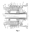
- the electric brake 1 of the invention is intended to brake an aircraft wheel 2 received on an axle 3 X axis to rotate about an axis of rotation X.
- the wheel 2 comprises a rim 4 carrying a tire not shown and which is mounted to turn on the axle 3 by means of bearings 5.
- the stack of discs 6 comprises, alternately, rotors discs 7 which are constrained to rotate with the rim 4 , and stator disks 10 which are constrained to remain attached to a torsion tube 12 itself immobilized in rotation.
- the stack of discs 6 extends between a fixed base 13 attached to the torsion tube 12, and an actuator holder 14 also attached to the torsion tube (by not shown fastening screws).
- the actuator holder 14 carries electromechanical actuators 15, each actuator 15 comprising here a first body 16 containing an electric motor 17, and a second body 18 receiving a pusher 19 movable axially facing the stack of disks 6 by means of the motor electrical 17 for controllably applying braking force to the disk stack 6.
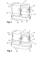
- the first body 16 and the second body 18 each comprise a running portion 22 of generally cylindrical shape and a foot portion 23 of generally cylindrical shape of smaller diameter than the current portion.
- the first body 16 and the second body 18 are secured at their foot portion 23 by a projecting base 24 enclosing a reducer.
- a groove 25 is thus defined between a face of the current portion and a face facing the projecting base 24.
- the first body 16 and the second body 18 each comprise a cylindrical running portion 26 around which is mounted a ring 27.
- the first body and the second body are secured at their foot portion by a projecting base 24.
- a groove 25 is thus defined between a face of the ring 27 and a face facing the projecting base 24.
- the brake comprises an actuator holder 14 which comprises a support 28 which defines four guide assemblies 31 comprising three parallel fingers 32 extending radially at the periphery of the support 28.
- the support 28 comprises a circular opening 33 allowing the passage of the axle, as well as orifices 34 for receiving the fixing screws of the actuator holder 14 on the torsion tube 12.
- Each guide assembly 31 is intended to to receive an actuator 15.
- the guide assemblies 31 are evenly distributed at the periphery of the central plate 28 of the actuator holder 14.
- the space between each finger 32 constitutes a reception space 35 for one of the bodies of the 15.
- Each receiving space has a semicircular recess 36 formed in the central plate 28. These semicircular recesses 36 define a position in service in which is positioned the actuator 15 when mounted on the actuator holder 14.
- the actuator 15 is guided in a radial direction Y between the fingers 32 of a guide assembly 31 of the actuator holder 14.
- the fingers 32 penetrate the grooves 25 of the bodies 16 , 18 of the actuator 15, so as to guide the bodies of the actuator 15 towards the semicircular recesses 36, and therefore the actuator 15 towards its position in service.
- the fingers 32 are shaped to provide guidance preventing axial movement of the actuator 15 during its assembly, except for a guide set.
- a flange 37 is then attached to the tips of the fingers 32 on bearing faces 38 of the fingers perpendicular to the radial mounting direction, so as to close the reception space 35 of the actuator and to block the actuator 15. in his service position.
- the flange 37 is then fixed on the bearing faces 38 of the fingers 32 by three fixing screws 39 screwed into three threaded orifices 42 in the fingers 32 and opening on the bearing faces 38.
- a first advantage of the invention lies in the radial direction Y of assembly and disassembly of the actuator. Indeed, on the landing gear of most aircraft, the actuators 15 have a large free space which extends opposite said actuators in the radial direction of assembly and disassembly, which allows to assemble and dismount the actuator 15 without disassembling the wheel and the brake.
- the position of the fixing screws 39 of the flange 37 makes their access relatively easy for an operator on the ground, which has sufficient space to operate a screwdriver to install or remove these screws.
- the robustness of the mounting of the actuators 15 is a second advantage of the invention.
- screw 39 are intended to fix the flange 37 whose role is to prevent any radial movement of the actuator 15.
- most of the forces exerted on the actuator 15 would tend to impart axial movement.
- maintaining the actuator in the axial position is provided mainly by the guide assemblies of the actuator holder 31, and therefore by the brake structure, and not by the screws for fixing the flange. . These are therefore subject to relatively small efforts.
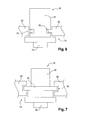
- the fingers 32 comprise a rib 42 which extends along the fingers 32 inside the reception areas.
- the rib 42 penetrates into the groove 25 of the second body 18 of the actuator 15 during the guiding of the actuator 15 in the actuator door 14.
- the fingers 32 comprise a groove 43 which extends along the fingers 32 inside the reception spaces
- the second body 18 of the actuator 15 comprises a ring 44 surrounding the body, which enters the throat 43 of the fingers 32 when guiding the actuator 15.
- the invention applies to any type of guide means having a groove and a protuberance.
Landscapes
- Engineering & Computer Science (AREA)
- General Engineering & Computer Science (AREA)
- Mechanical Engineering (AREA)
- Aviation & Aerospace Engineering (AREA)
- Braking Arrangements (AREA)
- Braking Systems And Boosters (AREA)
Abstract
Description
- L'invention concerne un frein électrique d'une roue d'aéronef comportant un porte-actionneurs qui porte au moins un actionneur électromécanique.
- Les systèmes de freinage de la plupart des aéronefs modernes comportent des freins à disques d'acier ou de carbone empilés autour d'un tube de torsion, et des actionneurs de freinage portés par un support et commandés pour appliquer un effort de freinage sur les disques en vue d'exercer sur les roues freinées de l'aéronef un couple de freinage tendant à ralentir celui-ci. Généralement, les roues freinées sont celles des atterrisseurs principaux des aéronefs.
- Les actionneurs des freins électromécaniques sont alimentés électriquement et comportent un moteur électrique adapté à déplacer un poussoir.
- Le montage de ces actionneurs sur le support, appelé porte-actionneurs dans le cas des freins électromécaniques, doit de préférence permettre un démontage d'un actionneur sans démonter la roue et le frein, ces manoeuvres étant relativement longues et complexes. Il est aussi bien sûr préférable de faciliter l'accès par un opérateur au sol aux moyens de fixation des actionneurs sur le porte-actionneurs, et leur manipulation.
- Le montage de ces actionneurs doit aussi répondre à des exigences de tenue mécanique. Les liaisons entre les actionneurs et le porte-actionneurs sont soumises à d'importantes contraintes mécaniques survenant principalement au moment d'un atterrissage et pendant la phase de freinage succédant à cet atterrissage. Généralement, les actionneurs sont vissés directement sur le porte-actionneurs. Les niveaux importants de chocs et de vibrations pouvant survenir lors de l'atterrissage et du freinage, ainsi que l'effort exercé par les poussoirs lors du freinage, peuvent provoquer des efforts transverses importants au niveau des vis de fixation.
- Le but de l'invention est de proposer un frein électrique de roue d'aéronef permettant un montage et un démontage aisés des actionneurs de freinage, et améliorant la robustesse du montage des actionneurs sur le porte-actionneurs.
- En vue de la réalisation de ce but, on propose un frein pour roue d'aéronef comportant un porte-actionneurs qui porte au moins un actionneur électromécanique comportant un poussoir déplaçable axialement selon un axe parallèle à un axe de rotation de la roue en regard d'éléments de friction pour appliquer sélectivement un effort de freinage sur les éléments de friction, le porte-actionneurs et l'actionneur comportant des moyens de guidage pour guider l'actionneur lors de son montage sur le porte-actionneurs selon une direction radiale jusqu'à une position en service, lesdits moyens de guidage formant un appui apte à assurer la transmission d'efforts de freinage de l'actionneur au porte-actionneurs, et des moyens de maintien en position de l'actionneur dans la position en service qui comprennent une bride fixée sur le porte actionneur pour immobiliser l'actionneur sur le porte-actionneurs dans la position de service.
- Le montage et le démontage de l'actionneur s'effectuent donc selon une direction radiale à l'axe de rotation de la roue. Hors, un espace libre important s'étend en regard des actionneurs dans cette direction radiale, ce qui facilite l'accès à l'actionneur et son démontage. Cette disposition autorise en particulier un démontage de l'actionneur sans démonter le frein et la roue, ce qui est par exemple impossible dans le cas d'un actionneur monté directement en regard de l'atterrisseur et prévu pour être démonté axialement. De plus, la plupart des contraintes mécaniques générées par des niveaux importants de chocs ou de vibrations, ou bien survenant en réaction à l'action du poussoir sur les éléments de friction, sont transmises sans solliciter les moyens de maintien en position de l'actionneur sur le porte-actionneurs.
- L'invention sera mieux comprise à la lumière de la description qui suit en référence aux figures des dessins annexés parmi lesquelles :
- la
figure 1 est une vue en coupe d'une roue d'aéronef munie d'un frein de l'invention, - les
figures 2 et 3 sont des vues schématiques en perspective d'un actionneur agencé pour être monté sur un porte-actionneurs d'un frein de l'invention selon un premier et un second mode de réalisation, - les
figures 4 et 5 sont des vues schématiques en perspective décrivant le montage des actionneurs sur un porte-actionneurs d'un frein de l'invention, un actionneur étant représenté démonté à lafigure 5 , - les
figures 6 à 7 représentent schématiquement des moyens de guidage d'un actionneur et d'un porte-actionneurs d'un frein de l'invention selon deux autres modes de réalisation. - Le frein électrique 1 de l'invention, visible à la
figure 1 , est destiné à freiner une roue 2 d'aéronef reçue sur un essieu 3 d'axe X pour tourner autour d'un axe de rotation X. La roue 2 comporte une jante 4 portant un pneumatique non représenté et qui est montée pour tourner sur l'essieu 3 au moyen de roulements 5. - On parlera dans la suite de direction axiale pour désigner une direction parallèle à l'axe X, et de direction radiale pour désigner une direction perpendiculaire à la direction précédente.
- A l'intérieur de la jante 4 s'étend une pile de disques 6 ayant un axe central coïncidant avec l'axe X. La pile de disques 6 comporte, en alternance, des disques rotors 7 qui sont astreints à tourner avec la jante 4, et des disques stators 10 qui sont astreints à rester solidaires d'un tube de torsion 12 lui-même immobilisé en rotation.
- La pile de disques 6 s'étend entre un fond 13 fixe rapporté sur le tube de torsion 12, et un porte-actionneurs 14 également rapporté sur le tube de torsion (par des vis de fixation non représentées). En référence aux
figures 1 à 5 , le porte-actionneurs 14 porte des actionneurs électromécaniques 15, chaque actionneur 15 comprenant ici un premier corps 16 contenant un moteur électrique 17, et un deuxième corps 18 recevant un poussoir 19 déplaçable axialement en regard de la pile de disques 6 au moyen du moteur électrique 17 pour appliquer de façon commandée un effort de freinage sur la pile de disques 6. - Dans un premier mode de réalisation, visible à la
figure 2 , le premier corps 16 et le deuxième corps 18 comportent chacun une partie courante 22 de forme générale cylindrique et une partie de pied 23 de forme générale cylindrique de diamètre inférieure à celui de la partie courante. Le premier corps 16 et le deuxième corps 18 sont solidarisés au niveau de leur partie de pied 23 par une embase saillante 24 renfermant un réducteur. Dans chaque corps, une gorge 25 est ainsi définie entre une face de la partie courante et une face en regard de l'embase saillante 24. - Dans un second mode de réalisation, visible à la
figure 3 , le premier corps 16 et le deuxième corps 18 comportent chacun une partie courante cylindrique 26 autour de laquelle est montée une bague 27. Le premier corps et le deuxième corps sont solidarisés au niveau de leur partie de pied par une embase saillante 24. Dans chaque corps, une gorge 25 est ainsi définie entre une face de la bague 27 et une face en regard de l'embase saillante 24. - En référence aux
figures 4 et 5 , sur lesquelles la pile de disques 6 a été simplifiée pour la clarté des dessins, le frein comprend un porte-actionneurs 14 qui comprend un support 28 qui définit quatre ensembles 31 de guidage comportant trois doigts 32 parallèles s'étendant radialement à la périphérie du support 28. Le support 28 comporte une ouverture circulaire 33 permettant le passage de l'essieu, ainsi que des orifices 34 permettant de recevoir les vis de fixation du porte-actionneurs 14 sur le tube de torsion 12. Chaque ensemble de guidage 31 est destiné à recevoir un actionneur 15. Les ensembles de guidage 31 sont régulièrement répartis à la périphérie de la plaque centrale 28 du porte-actionneurs 14. L'espace entre chaque doigt 32 constitue un espace d'accueil 35 pour l'un des corps de l'actionneur 15. Chaque espace d'accueil comporte un évidement semi-circulaire 36 formé dans la plaque centrale 28. Ces évidements semi-circulaires 36 définissent une position en service dans laquelle est positionné l'actionneur 15 lorsqu'il est monté sur le porte-actionneurs 14. - Lors de son montage sur le porte-actionneurs 14, l'actionneur 15 est guidé selon une direction radiale Y entre les doigts 32 d'un ensemble de guidage 31 du porte-actionneurs 14. Les doigts 32 pénètrent dans les gorges 25 des corps 16, 18 de l'actionneur 15, de manière à guider les corps de l'actionneur 15 vers les évidements semi-circulaires 36, et donc l'actionneur 15 vers sa position en service. Les doigts 32 sont conformés pour assurer un guidage empêchant tout mouvement axial de l'actionneur 15 lors de son montage, hormis un jeu de guidage.
- Une bride 37 est ensuite rapportée au bout des doigts 32 sur des faces d'appui 38 des doigts perpendiculaires à la direction radiale de montage, de manière à refermer l'espace d'accueil 35 de l'actionneur et à bloquer l'actionneur 15 dans sa position de service. La bride 37 est ensuite fixée sur les faces d'appui 38 des doigts 32 par trois vis de fixation 39 vissées dans trois orifices taraudés 42 dans les des doigts 32 et débouchant sur les faces d'appui 38.
- Pour démonter l'actionneur, il suffit de dévisser les vis de fixation 39, de retirer la bride 37, et de faire glisser l'actionneur 15 radialement vers l'extérieur du porte-actionneurs 14.
- Un premier avantage de l'invention réside dans la direction radiale Y de montage et de démontage de l'actionneur. En effet, sur les atterrisseurs de la plupart des avions, les actionneurs 15 disposent d'un espace libre important qui s'étend en regard desdits actionneurs dans la direction radiale de montage et de démontage, ce qui permet de monter et de démonter l'actionneur 15 sans démonter la roue et le frein. De plus, la position des vis de fixation 39 de la bride 37 rend leur accès relativement aisé pour un opérateur au sol, qui dispose d'un espace suffisant pour manoeuvrer un tournevis pour installer ou retirer ces vis.
- La robustesse du montage des actionneurs 15 est un second avantage de l'invention. Lors d'un atterrissage et d'un freinage, les contraintes résultant des chocs, des vibrations et de l'effort exercé par le poussoir sur les disques, ne génèrent pas de travail en cisaillement sur les vis de fixation 39. De plus, ces vis de fixation 39 sont destinées à fixer la bride 37 dont le rôle est d'empêcher tout mouvement radial de l'actionneur 15. Hors, la plupart des forces exercées sur l'actionneur 15 auraient tendance à lui conférer un mouvement axial. Dans le frein électrique de l'invention, le maintien de l'actionneur en position axiale est assuré principalement par les ensembles de guidage du porte-actionneurs 31, et donc par la structure du frein, et non par les vis de fixation de la bride. Celles-ci sont donc soumises à des efforts relativement faibles.
- Les
figures 6 et 7 , sur lesquelles seul le deuxième corps 18 de l'actionneur 15 est visible, représentent des variantes de réalisation des moyens de guidage d'un actionneur 15 dans le porte-actionneurs 14. - En référence à la
figure 6 , les doigts 32 comportent une nervure 42 qui s'étend le long des doigts 32 à l'intérieur des espaces d'accueil. La nervure 42 pénètre dans la gorge 25 du deuxième corps 18 de l'actionneur 15 lors du guidage de l'actionneur 15 dans le porte actionneur 14. - En référence à la
figure 7 , les doigts 32 comportent une gorge 43 qui s'étend le long des doigts 32 à l'intérieur des espaces d'accueil, et le deuxième corps 18 de l'actionneur 15 comporte une bague 44 entourant le corps, qui pénètre dans la gorge 43 des doigts 32 lors du guidage de l'actionneur 15. - L'invention n'est pas limitée au mode de réalisation particulier qui vient d'être décrit, mais, bien au contraire, couvre toute variante entrant dans le cadre de l'invention tel que défini par les revendications.
- Bien que l'on ait utilisé une architecture particulière de frein électrique pour décrire l'invention, comprenant un certain nombre d'actionneurs électromécaniques, l'invention est bien sûr applicable à tout type de frein comportant un porte-actionneurs et au moins un actionneur électromécanique.
- Bien que l'on ait utilisé une bride agencée pour être fixée à l'aide de vis s'étendant radialement dans le porte-actionneurs, il est possible que cette bride soit montée de façon différente, du moment qu'elle immobilise l'actionneur dans sa position de service en empêchant tout mouvement radial de celui-ci.
- Bien que l'on ait fourni un certain nombre de modes de réalisations des moyens de guidage de l'actionneur dans le porte-actionneurs, l'invention s'applique à tout type de moyens de guidage comportant une gorge et une protubérance.
Claims (7)
- Frein pour roue d'aéronef comportant un porte-actionneurs (14) qui porte au moins un actionneur électromécanique (15) comportant un poussoir (19) déplaçable selon une direction parallèle à un axe de rotation (X) de la roue (2) en regard d'éléments de friction (7, 10) pour appliquer sélectivement un effort de freinage sur les éléments de friction (7, 10), le porte-actionneurs (14) et l'actionneur (15) comportant des moyens de guidage (25, 32) pour guider l'actionneur (15) lors de son montage sur le porte-actionneurs (14) selon une direction radiale (Y) jusqu'à une position en service, lesdits moyens de guidage formant un appui apte à assurer la transmission d'efforts de freinage de l'actionneur au porte-actionneurs, et des moyens de maintien en position (37) de l'actionneur dans la position en service, caractérisé en ce que les moyens de maintien en position (37) comprennent une bride (37) fixée sur le porte-actionneurs (14) pour immobiliser l'actionneur (15) sur le porte-actionneurs (14) en position de service.
- Frein selon la revendication 1, dans lequel la bride (37) est démontable radialement et est fixée au porte-actionneurs (14) par des moyens de fixation (39) comprenant au moins une vis (39) s'étendant radialement.
- Frein selon la revendication 2, dans lequel la bride (37) vient porter contre une face d'appui du porte-actionneurs (38) perpendiculaire à la direction radiale (Y) de montage de l'actionneur (15).
- Frein selon la revendication 1, dans lequel les moyens de guidage (25, 32) forment, sur l'un du porte-actionneurs (14) et de l'actionneur (15), une gorge (25), et sur l'autre, forment une protubérance (32, 42) adaptée à pénétrer dans la gorge (25) pour réaliser un guidage radial de l'actionneur (15) dans le porte-actionneurs (14).
- Frein selon la revendication 4, dans lequel la gorge (25) est définie sur l'actionneur entre une face d'une bague (27) entourant un corps (16, 18) de l'actionneur (15) et une face en regard d'une embase saillante (24) du corps (16, 18) de l'actionneur (15).
- Frein selon la revendication 4, dans lequel la protubérance est définie sur l'actionneur (15) par une bague (44) entourant un corps (16, 18) de l'actionneur (15).
- Frein selon la revendication 1, dans lequel les moyens de guidage (25, 32) sont conformés pour assurer un guidage positif empêchant tout mouvement axial de l'actionneur (15) lors de son montage.
Applications Claiming Priority (1)
| Application Number | Priority Date | Filing Date | Title |
|---|---|---|---|
| FR1254293A FR2990413B1 (fr) | 2012-05-10 | 2012-05-10 | Frein pour roue d'aeronef |
Publications (2)
| Publication Number | Publication Date |
|---|---|
| EP2662283A1 true EP2662283A1 (fr) | 2013-11-13 |
| EP2662283B1 EP2662283B1 (fr) | 2018-07-04 |
Family
ID=48184117
Family Applications (1)
| Application Number | Title | Priority Date | Filing Date |
|---|---|---|---|
| EP13166701.6A Active EP2662283B1 (fr) | 2012-05-10 | 2013-05-06 | Frein pour roue d`aéronef |
Country Status (6)
| Country | Link |
|---|---|
| US (1) | US9187172B2 (fr) |
| EP (1) | EP2662283B1 (fr) |
| CN (1) | CN103388635A (fr) |
| BR (1) | BR102013011553A2 (fr) |
| CA (1) | CA2816159C (fr) |
| FR (1) | FR2990413B1 (fr) |
Cited By (1)
| Publication number | Priority date | Publication date | Assignee | Title |
|---|---|---|---|---|
| CN107685851A (zh) * | 2016-08-05 | 2018-02-13 | 赛峰起落架系统英国有限公司 | 飞行器起落架组件 |
Families Citing this family (12)
| Publication number | Priority date | Publication date | Assignee | Title |
|---|---|---|---|---|
| FR3021378B1 (fr) * | 2014-05-21 | 2016-06-03 | Messier Bugatti Dowty | Frein a disques pour roue d'aeronef |
| CN105221608A (zh) * | 2014-06-23 | 2016-01-06 | 杨皓捷 | 一种多摩擦片刹车系统 |
| EP3064432B1 (fr) | 2015-03-05 | 2017-08-09 | Safran Landing Systems UK Limited | Ensemble de train d'atterrissage d'avion |
| US9995353B2 (en) * | 2015-12-21 | 2018-06-12 | Goodrich Corporation | Modified actuator design to improve load distribution and damping |
| CN106394877B (zh) * | 2016-10-13 | 2018-08-07 | 西安航空制动科技有限公司 | 一种飞机刹车装置的刹车壳体和承压杯 |
| CN106763316A (zh) * | 2016-12-22 | 2017-05-31 | 山河智能装备股份有限公司 | 一种回转制动装置 |
| FR3061138B1 (fr) * | 2016-12-23 | 2021-12-10 | Safran Landing Systems | Atterrisseur d'aeronef equipe d'une roue freinee |
| US10228030B2 (en) * | 2017-05-15 | 2019-03-12 | Goodrich Corporation | Multi-disk brake assembly with travel limit pin |
| US12179912B2 (en) * | 2020-09-29 | 2024-12-31 | Goodrich Corporation | Hybrid brake system |
| US11999468B2 (en) | 2022-02-10 | 2024-06-04 | Goodrich Corporation | Hybrid brake systems and methods |
| US12486050B2 (en) | 2022-02-10 | 2025-12-02 | Goodrich Corporation | Hybrid brake systems and methods |
| US11970263B2 (en) | 2022-02-10 | 2024-04-30 | Goodrich Corporation | Hybrid brake systems and methods for load cell calibration |
Citations (3)
| Publication number | Priority date | Publication date | Assignee | Title |
|---|---|---|---|---|
| EP1084949A2 (fr) * | 1999-09-13 | 2001-03-21 | The B.F. Goodrich Company | Frein multidisques pour avions |
| EP1533536A1 (fr) * | 2003-11-14 | 2005-05-25 | Messier-Bugatti | Atterrisseur, frein pour roue d'aéronef, ensemble de roue freinée d'aréonef, et procédé de maintenance d'un tel atterrisseur |
| US20060042889A1 (en) * | 2004-08-31 | 2006-03-02 | Honeywell International Inc. | Brake carrier having improved electromechanical actuator and mounting arrangement therefor |
Family Cites Families (5)
| Publication number | Priority date | Publication date | Assignee | Title |
|---|---|---|---|---|
| US4175651A (en) * | 1977-03-28 | 1979-11-27 | Montalvo Edwin J Sr | Air/mercury actuation of brakes and clutches |
| US4442931A (en) * | 1981-06-15 | 1984-04-17 | Montalvo Sr Edwin J | Air actuated force intensifying piston and cylinder assembly for brakes and clutches |
| EP2060821A1 (fr) * | 2007-11-14 | 2009-05-20 | Goodrich Corporation | Frein d'avion et procédé doté de modules d'actionnement électromécaniques |
| US8813936B2 (en) * | 2008-07-25 | 2014-08-26 | Eaton Corporation | Force transmitting assembly |
| US20100170755A1 (en) * | 2009-01-05 | 2010-07-08 | Robert Biggs | Modular brake caliper |
-
2012
- 2012-05-10 FR FR1254293A patent/FR2990413B1/fr active Active
-
2013
- 2013-05-06 EP EP13166701.6A patent/EP2662283B1/fr active Active
- 2013-05-08 US US13/889,857 patent/US9187172B2/en active Active
- 2013-05-08 CA CA2816159A patent/CA2816159C/fr active Active
- 2013-05-09 BR BRBR102013011553-3A patent/BR102013011553A2/pt not_active IP Right Cessation
- 2013-05-09 CN CN2013101694439A patent/CN103388635A/zh active Pending
Patent Citations (3)
| Publication number | Priority date | Publication date | Assignee | Title |
|---|---|---|---|---|
| EP1084949A2 (fr) * | 1999-09-13 | 2001-03-21 | The B.F. Goodrich Company | Frein multidisques pour avions |
| EP1533536A1 (fr) * | 2003-11-14 | 2005-05-25 | Messier-Bugatti | Atterrisseur, frein pour roue d'aéronef, ensemble de roue freinée d'aréonef, et procédé de maintenance d'un tel atterrisseur |
| US20060042889A1 (en) * | 2004-08-31 | 2006-03-02 | Honeywell International Inc. | Brake carrier having improved electromechanical actuator and mounting arrangement therefor |
Cited By (1)
| Publication number | Priority date | Publication date | Assignee | Title |
|---|---|---|---|---|
| CN107685851A (zh) * | 2016-08-05 | 2018-02-13 | 赛峰起落架系统英国有限公司 | 飞行器起落架组件 |
Also Published As
| Publication number | Publication date |
|---|---|
| CN103388635A (zh) | 2013-11-13 |
| FR2990413A1 (fr) | 2013-11-15 |
| BR102013011553A2 (pt) | 2015-06-30 |
| US20130299286A1 (en) | 2013-11-14 |
| FR2990413B1 (fr) | 2014-06-06 |
| CA2816159C (fr) | 2016-07-05 |
| CA2816159A1 (fr) | 2013-11-10 |
| EP2662283B1 (fr) | 2018-07-04 |
| US9187172B2 (en) | 2015-11-17 |
Similar Documents
| Publication | Publication Date | Title |
|---|---|---|
| EP2662283B1 (fr) | Frein pour roue d`aéronef | |
| EP1533536B1 (fr) | Frein pour roue d'aéronef, ensemble de roue freinée d'aréonef, et atterrisseur comportant une telle roue d'aéronef | |
| EP2992236B2 (fr) | Frein à disque à étrier fixe et à patins de frein stabilisés, et procédés associés d'assemblage et de remplacement d'un patin | |
| EP2889155B1 (fr) | Jante de roue d'aéronef à talon amovible | |
| EP2876326B1 (fr) | Procédé de rénovation et d'utilisation de disques de frein de type stator arrière à plots, disque assemblé et pile de disques correspondante | |
| EP2361830A1 (fr) | Ensemble de roue et frein pour aéronef équipé d'un dispositif d'entraînement en rotation | |
| EP2746611B1 (fr) | Roue d'aéronef équipée de boulons-barrettes | |
| FR2463325A1 (fr) | Frein a disque | |
| EP0366509B1 (fr) | Frein à deux disques d'écartement fixe | |
| EP2816251B1 (fr) | Frein pour roue d'aéronef, en particulier pour un hélicoptère. | |
| EP0143708A2 (fr) | Frein multidisque perfectionne | |
| EP1793139B1 (fr) | Frein électromécanique avec actionneurs ayant un débattement angulaire | |
| EP0683870A1 (fr) | Dispositif a plateaux a billes et a cage de centrage. | |
| EP2955109B1 (fr) | Roue d'aéronef équipée de moyens de son entraînement en rotation par un actionneur d'entraînement | |
| EP3025957B1 (fr) | Procédé de fixation d'un actionneur d'entraînement en rotation d'une roue d'aéronef | |
| EP0340058B1 (fr) | Frein à disques multiples | |
| CA3044094C (fr) | Systeme de freinage a disque et aeronef | |
| FR2976038A1 (fr) | Dispositif de freinage a etrier flottant avec montage radial direct ou indirect de l'etrier | |
| WO2025168362A1 (fr) | Dispositif de freinage à disque comprenant un passage pour des plaquettes de frein formé entre une couronne de support du disque et un support latéral | |
| EP4616082A1 (fr) | Système de freinage ferroviaire pour véhicule ferroviaire et procédé d'assemblage et/ou désassemblage d'un système de freinage ferroviaire | |
| FR2813580A1 (fr) | Dispositif de freinage pour une roue d'avion | |
| EP2708465A1 (fr) | Procédé de fixation d'un organe d'entraînement de roue d'aéronef sur l'atterrisseur portant la roue. | |
| EP0292360A2 (fr) | Frein à disque à étrier en un matériau présentant une faible résistance à la pression | |
| FR2721980A1 (fr) | Dispositif de fixation rapide d'un element a un support |
Legal Events
| Date | Code | Title | Description |
|---|---|---|---|
| PUAI | Public reference made under article 153(3) epc to a published international application that has entered the european phase |
Free format text: ORIGINAL CODE: 0009012 |
|
| AK | Designated contracting states |
Kind code of ref document: A1 Designated state(s): AL AT BE BG CH CY CZ DE DK EE ES FI FR GB GR HR HU IE IS IT LI LT LU LV MC MK MT NL NO PL PT RO RS SE SI SK SM TR |
|
| AX | Request for extension of the european patent |
Extension state: BA ME |
|
| 17P | Request for examination filed |
Effective date: 20140428 |
|
| RBV | Designated contracting states (corrected) |
Designated state(s): AL AT BE BG CH CY CZ DE DK EE ES FI FR GB GR HR HU IE IS IT LI LT LU LV MC MK MT NL NO PL PT RO RS SE SI SK SM TR |
|
| 17Q | First examination report despatched |
Effective date: 20160805 |
|
| RAP1 | Party data changed (applicant data changed or rights of an application transferred) |
Owner name: SAFRAN LANDING SYSTEMS |
|
| RAP1 | Party data changed (applicant data changed or rights of an application transferred) |
Owner name: SAFRAN LANDING SYSTEMS |
|
| STAA | Information on the status of an ep patent application or granted ep patent |
Free format text: STATUS: EXAMINATION IS IN PROGRESS |
|
| GRAP | Despatch of communication of intention to grant a patent |
Free format text: ORIGINAL CODE: EPIDOSNIGR1 |
|
| STAA | Information on the status of an ep patent application or granted ep patent |
Free format text: STATUS: GRANT OF PATENT IS INTENDED |
|
| INTG | Intention to grant announced |
Effective date: 20171127 |
|
| GRAS | Grant fee paid |
Free format text: ORIGINAL CODE: EPIDOSNIGR3 |
|
| GRAA | (expected) grant |
Free format text: ORIGINAL CODE: 0009210 |
|
| STAA | Information on the status of an ep patent application or granted ep patent |
Free format text: STATUS: THE PATENT HAS BEEN GRANTED |
|
| AK | Designated contracting states |
Kind code of ref document: B1 Designated state(s): AL AT BE BG CH CY CZ DE DK EE ES FI FR GB GR HR HU IE IS IT LI LT LU LV MC MK MT NL NO PL PT RO RS SE SI SK SM TR |
|
| REG | Reference to a national code |
Ref country code: GB Ref legal event code: FG4D Free format text: NOT ENGLISH |
|
| REG | Reference to a national code |
Ref country code: CH Ref legal event code: EP |
|
| REG | Reference to a national code |
Ref country code: AT Ref legal event code: REF Ref document number: 1014208 Country of ref document: AT Kind code of ref document: T Effective date: 20180715 |
|
| REG | Reference to a national code |
Ref country code: IE Ref legal event code: FG4D Free format text: LANGUAGE OF EP DOCUMENT: FRENCH |
|
| REG | Reference to a national code |
Ref country code: DE Ref legal event code: R096 Ref document number: 602013039617 Country of ref document: DE |
|
| REG | Reference to a national code |
Ref country code: NL Ref legal event code: MP Effective date: 20180704 |
|
| REG | Reference to a national code |
Ref country code: LT Ref legal event code: MG4D |
|
| REG | Reference to a national code |
Ref country code: AT Ref legal event code: MK05 Ref document number: 1014208 Country of ref document: AT Kind code of ref document: T Effective date: 20180704 |
|
| PG25 | Lapsed in a contracting state [announced via postgrant information from national office to epo] |
Ref country code: NL Free format text: LAPSE BECAUSE OF FAILURE TO SUBMIT A TRANSLATION OF THE DESCRIPTION OR TO PAY THE FEE WITHIN THE PRESCRIBED TIME-LIMIT Effective date: 20180704 |
|
| PG25 | Lapsed in a contracting state [announced via postgrant information from national office to epo] |
Ref country code: SE Free format text: LAPSE BECAUSE OF FAILURE TO SUBMIT A TRANSLATION OF THE DESCRIPTION OR TO PAY THE FEE WITHIN THE PRESCRIBED TIME-LIMIT Effective date: 20180704 Ref country code: RS Free format text: LAPSE BECAUSE OF FAILURE TO SUBMIT A TRANSLATION OF THE DESCRIPTION OR TO PAY THE FEE WITHIN THE PRESCRIBED TIME-LIMIT Effective date: 20180704 Ref country code: GR Free format text: LAPSE BECAUSE OF FAILURE TO SUBMIT A TRANSLATION OF THE DESCRIPTION OR TO PAY THE FEE WITHIN THE PRESCRIBED TIME-LIMIT Effective date: 20181005 Ref country code: LT Free format text: LAPSE BECAUSE OF FAILURE TO SUBMIT A TRANSLATION OF THE DESCRIPTION OR TO PAY THE FEE WITHIN THE PRESCRIBED TIME-LIMIT Effective date: 20180704 Ref country code: BG Free format text: LAPSE BECAUSE OF FAILURE TO SUBMIT A TRANSLATION OF THE DESCRIPTION OR TO PAY THE FEE WITHIN THE PRESCRIBED TIME-LIMIT Effective date: 20181004 Ref country code: PL Free format text: LAPSE BECAUSE OF FAILURE TO SUBMIT A TRANSLATION OF THE DESCRIPTION OR TO PAY THE FEE WITHIN THE PRESCRIBED TIME-LIMIT Effective date: 20180704 Ref country code: CZ Free format text: LAPSE BECAUSE OF FAILURE TO SUBMIT A TRANSLATION OF THE DESCRIPTION OR TO PAY THE FEE WITHIN THE PRESCRIBED TIME-LIMIT Effective date: 20180704 Ref country code: FI Free format text: LAPSE BECAUSE OF FAILURE TO SUBMIT A TRANSLATION OF THE DESCRIPTION OR TO PAY THE FEE WITHIN THE PRESCRIBED TIME-LIMIT Effective date: 20180704 Ref country code: NO Free format text: LAPSE BECAUSE OF FAILURE TO SUBMIT A TRANSLATION OF THE DESCRIPTION OR TO PAY THE FEE WITHIN THE PRESCRIBED TIME-LIMIT Effective date: 20181004 Ref country code: IS Free format text: LAPSE BECAUSE OF FAILURE TO SUBMIT A TRANSLATION OF THE DESCRIPTION OR TO PAY THE FEE WITHIN THE PRESCRIBED TIME-LIMIT Effective date: 20181104 Ref country code: AT Free format text: LAPSE BECAUSE OF FAILURE TO SUBMIT A TRANSLATION OF THE DESCRIPTION OR TO PAY THE FEE WITHIN THE PRESCRIBED TIME-LIMIT Effective date: 20180704 |
|
| PG25 | Lapsed in a contracting state [announced via postgrant information from national office to epo] |
Ref country code: LV Free format text: LAPSE BECAUSE OF FAILURE TO SUBMIT A TRANSLATION OF THE DESCRIPTION OR TO PAY THE FEE WITHIN THE PRESCRIBED TIME-LIMIT Effective date: 20180704 Ref country code: HR Free format text: LAPSE BECAUSE OF FAILURE TO SUBMIT A TRANSLATION OF THE DESCRIPTION OR TO PAY THE FEE WITHIN THE PRESCRIBED TIME-LIMIT Effective date: 20180704 Ref country code: ES Free format text: LAPSE BECAUSE OF FAILURE TO SUBMIT A TRANSLATION OF THE DESCRIPTION OR TO PAY THE FEE WITHIN THE PRESCRIBED TIME-LIMIT Effective date: 20180704 Ref country code: AL Free format text: LAPSE BECAUSE OF FAILURE TO SUBMIT A TRANSLATION OF THE DESCRIPTION OR TO PAY THE FEE WITHIN THE PRESCRIBED TIME-LIMIT Effective date: 20180704 |
|
| REG | Reference to a national code |
Ref country code: DE Ref legal event code: R097 Ref document number: 602013039617 Country of ref document: DE |
|
| PG25 | Lapsed in a contracting state [announced via postgrant information from national office to epo] |
Ref country code: RO Free format text: LAPSE BECAUSE OF FAILURE TO SUBMIT A TRANSLATION OF THE DESCRIPTION OR TO PAY THE FEE WITHIN THE PRESCRIBED TIME-LIMIT Effective date: 20180704 Ref country code: IT Free format text: LAPSE BECAUSE OF FAILURE TO SUBMIT A TRANSLATION OF THE DESCRIPTION OR TO PAY THE FEE WITHIN THE PRESCRIBED TIME-LIMIT Effective date: 20180704 Ref country code: EE Free format text: LAPSE BECAUSE OF FAILURE TO SUBMIT A TRANSLATION OF THE DESCRIPTION OR TO PAY THE FEE WITHIN THE PRESCRIBED TIME-LIMIT Effective date: 20180704 |
|
| PLBE | No opposition filed within time limit |
Free format text: ORIGINAL CODE: 0009261 |
|
| STAA | Information on the status of an ep patent application or granted ep patent |
Free format text: STATUS: NO OPPOSITION FILED WITHIN TIME LIMIT |
|
| PG25 | Lapsed in a contracting state [announced via postgrant information from national office to epo] |
Ref country code: SK Free format text: LAPSE BECAUSE OF FAILURE TO SUBMIT A TRANSLATION OF THE DESCRIPTION OR TO PAY THE FEE WITHIN THE PRESCRIBED TIME-LIMIT Effective date: 20180704 Ref country code: SM Free format text: LAPSE BECAUSE OF FAILURE TO SUBMIT A TRANSLATION OF THE DESCRIPTION OR TO PAY THE FEE WITHIN THE PRESCRIBED TIME-LIMIT Effective date: 20180704 Ref country code: DK Free format text: LAPSE BECAUSE OF FAILURE TO SUBMIT A TRANSLATION OF THE DESCRIPTION OR TO PAY THE FEE WITHIN THE PRESCRIBED TIME-LIMIT Effective date: 20180704 |
|
| 26N | No opposition filed |
Effective date: 20190405 |
|
| PG25 | Lapsed in a contracting state [announced via postgrant information from national office to epo] |
Ref country code: SI Free format text: LAPSE BECAUSE OF FAILURE TO SUBMIT A TRANSLATION OF THE DESCRIPTION OR TO PAY THE FEE WITHIN THE PRESCRIBED TIME-LIMIT Effective date: 20180704 |
|
| REG | Reference to a national code |
Ref country code: CH Ref legal event code: PL |
|
| PG25 | Lapsed in a contracting state [announced via postgrant information from national office to epo] |
Ref country code: CH Free format text: LAPSE BECAUSE OF NON-PAYMENT OF DUE FEES Effective date: 20190531 Ref country code: LI Free format text: LAPSE BECAUSE OF NON-PAYMENT OF DUE FEES Effective date: 20190531 Ref country code: MC Free format text: LAPSE BECAUSE OF FAILURE TO SUBMIT A TRANSLATION OF THE DESCRIPTION OR TO PAY THE FEE WITHIN THE PRESCRIBED TIME-LIMIT Effective date: 20180704 |
|
| REG | Reference to a national code |
Ref country code: BE Ref legal event code: MM Effective date: 20190531 |
|
| PG25 | Lapsed in a contracting state [announced via postgrant information from national office to epo] |
Ref country code: LU Free format text: LAPSE BECAUSE OF NON-PAYMENT OF DUE FEES Effective date: 20190506 |
|
| PG25 | Lapsed in a contracting state [announced via postgrant information from national office to epo] |
Ref country code: TR Free format text: LAPSE BECAUSE OF FAILURE TO SUBMIT A TRANSLATION OF THE DESCRIPTION OR TO PAY THE FEE WITHIN THE PRESCRIBED TIME-LIMIT Effective date: 20180704 |
|
| PG25 | Lapsed in a contracting state [announced via postgrant information from national office to epo] |
Ref country code: IE Free format text: LAPSE BECAUSE OF NON-PAYMENT OF DUE FEES Effective date: 20190506 |
|
| PG25 | Lapsed in a contracting state [announced via postgrant information from national office to epo] |
Ref country code: BE Free format text: LAPSE BECAUSE OF NON-PAYMENT OF DUE FEES Effective date: 20190531 |
|
| PG25 | Lapsed in a contracting state [announced via postgrant information from national office to epo] |
Ref country code: PT Free format text: LAPSE BECAUSE OF FAILURE TO SUBMIT A TRANSLATION OF THE DESCRIPTION OR TO PAY THE FEE WITHIN THE PRESCRIBED TIME-LIMIT Effective date: 20181105 |
|
| PG25 | Lapsed in a contracting state [announced via postgrant information from national office to epo] |
Ref country code: CY Free format text: LAPSE BECAUSE OF FAILURE TO SUBMIT A TRANSLATION OF THE DESCRIPTION OR TO PAY THE FEE WITHIN THE PRESCRIBED TIME-LIMIT Effective date: 20180704 |
|
| PG25 | Lapsed in a contracting state [announced via postgrant information from national office to epo] |
Ref country code: HU Free format text: LAPSE BECAUSE OF FAILURE TO SUBMIT A TRANSLATION OF THE DESCRIPTION OR TO PAY THE FEE WITHIN THE PRESCRIBED TIME-LIMIT; INVALID AB INITIO Effective date: 20130506 Ref country code: MT Free format text: LAPSE BECAUSE OF FAILURE TO SUBMIT A TRANSLATION OF THE DESCRIPTION OR TO PAY THE FEE WITHIN THE PRESCRIBED TIME-LIMIT Effective date: 20180704 |
|
| PG25 | Lapsed in a contracting state [announced via postgrant information from national office to epo] |
Ref country code: MK Free format text: LAPSE BECAUSE OF FAILURE TO SUBMIT A TRANSLATION OF THE DESCRIPTION OR TO PAY THE FEE WITHIN THE PRESCRIBED TIME-LIMIT Effective date: 20180704 |
|
| PGFP | Annual fee paid to national office [announced via postgrant information from national office to epo] |
Ref country code: DE Payment date: 20250519 Year of fee payment: 13 |
|
| PGFP | Annual fee paid to national office [announced via postgrant information from national office to epo] |
Ref country code: GB Payment date: 20250527 Year of fee payment: 13 |
|
| PGFP | Annual fee paid to national office [announced via postgrant information from national office to epo] |
Ref country code: FR Payment date: 20250526 Year of fee payment: 13 |