EP2060821A1 - Frein d'avion et procédé doté de modules d'actionnement électromécaniques - Google Patents
Frein d'avion et procédé doté de modules d'actionnement électromécaniques Download PDFInfo
- Publication number
- EP2060821A1 EP2060821A1 EP08169182A EP08169182A EP2060821A1 EP 2060821 A1 EP2060821 A1 EP 2060821A1 EP 08169182 A EP08169182 A EP 08169182A EP 08169182 A EP08169182 A EP 08169182A EP 2060821 A1 EP2060821 A1 EP 2060821A1
- Authority
- EP
- European Patent Office
- Prior art keywords
- brake
- module
- actuator
- head
- brake head
- Prior art date
- Legal status (The legal status is an assumption and is not a legal conclusion. Google has not performed a legal analysis and makes no representation as to the accuracy of the status listed.)
- Withdrawn
Links
Images


Classifications
-
- F—MECHANICAL ENGINEERING; LIGHTING; HEATING; WEAPONS; BLASTING
- F16—ENGINEERING ELEMENTS AND UNITS; GENERAL MEASURES FOR PRODUCING AND MAINTAINING EFFECTIVE FUNCTIONING OF MACHINES OR INSTALLATIONS; THERMAL INSULATION IN GENERAL
- F16D—COUPLINGS FOR TRANSMITTING ROTATION; CLUTCHES; BRAKES
- F16D65/00—Parts or details
- F16D65/0043—Brake maintenance and assembly, tools therefor
-
- F—MECHANICAL ENGINEERING; LIGHTING; HEATING; WEAPONS; BLASTING
- F16—ENGINEERING ELEMENTS AND UNITS; GENERAL MEASURES FOR PRODUCING AND MAINTAINING EFFECTIVE FUNCTIONING OF MACHINES OR INSTALLATIONS; THERMAL INSULATION IN GENERAL
- F16D—COUPLINGS FOR TRANSMITTING ROTATION; CLUTCHES; BRAKES
- F16D55/00—Brakes with substantially-radial braking surfaces pressed together in axial direction, e.g. disc brakes
- F16D2055/0075—Constructional features of axially engaged brakes
- F16D2055/0091—Plural actuators arranged side by side on the same side of the rotor
-
- Y—GENERAL TAGGING OF NEW TECHNOLOGICAL DEVELOPMENTS; GENERAL TAGGING OF CROSS-SECTIONAL TECHNOLOGIES SPANNING OVER SEVERAL SECTIONS OF THE IPC; TECHNICAL SUBJECTS COVERED BY FORMER USPC CROSS-REFERENCE ART COLLECTIONS [XRACs] AND DIGESTS
- Y10—TECHNICAL SUBJECTS COVERED BY FORMER USPC
- Y10T—TECHNICAL SUBJECTS COVERED BY FORMER US CLASSIFICATION
- Y10T29/00—Metal working
- Y10T29/49—Method of mechanical manufacture
- Y10T29/49718—Repairing
Definitions
- the invention herein described relates generally to brakes and methods, more particularly to brakes and methods using electromechanical actuators, and still more particularly to electrically actuated aircraft brakes and methods.
- Aircraft wheel and brakes heretofore have included a non-rotatable wheel support, a wheel rotatably mounted to the wheel support, and a brake disk stack having alternating rotor and stator disks mounted with respect to the wheel support and wheel for relative axial movement.
- Each rotor disk is coupled to the wheel for rotation therewith and each stator disk is coupled to the wheel support against rotation.
- a back plate is located at the rear end of the disk pack and a brake head is located at the front end.
- the brake head may house a plurality of actuator rams that extend to compress the brake disk stack against the back plate, Torque is taken out by the stator disks through a static torque tube or the like,
- U.S. Patent No. 4,596,316 another configuration of an electrically actuated brake uses a roller screw drive wherein a ring gear member interacts through a plurality of roller screws to drive a ram member into engagement with a brake pressure plate to effect compression of the brake disk stack for braking action.
- a plurality of electric motors and their associated pinions drive a ring gear into rotation and the plurality of roller screws effect linear axial movement of the ram member.
- a further electrically actuated aircraft brake employs a roller screw drive mechanism driven by an electric torque motor through a gear drive associated with either the screw or the nut of the roller screw drive mechanism. Rotation of the gear drive by the torque motor moves the other one of the screw or nut into axial engagement with a brake disk stack to compress the stack for braking.
- a plurality of the roller screw drive mechanisms and respective gear drives and torque motors are assembled in a brake head in a balanced arrangement about the axis of the wheel to apply and release a brake pressure force on the brake disk stack in response to an electrical control signal to the torque motors.
- the brake system includes a brake disk stack, a brake head, and at least one actuator module mounted to the brake head.
- the actuator module includes a module housing, a reciprocating ram and a motive device operatively connected to the reciprocating ram for selectively moving the reciprocating ram into and out of forceful engagement with the brake disk stack for applying and releasing braking force.
- the actuator module is mounted to a surface of the brake head that is parallel to a friction surface of the brake disk stack. While this mounting configuration is adequate for many applications, removal and/or installation of the modules on a brake head can be difficult especially in applications having limited space for movement of the module in an axial direction.
- the present invention provides a brake and method characterized by radial mount actuator modules each of which can be easily and quickly replaced as a unit.
- the radial mount actuators eliminate the need for a mounting surface parallel to the friction surface of the brake stack thereby reducing the overall weight of the brake. Further, the radial mount actuators enable quick and easy replacement of the actuator modules, preferably without requiring disassembly of the overall brake and wheel assembly, even in applications that have limited space axially adjacent to the brake.
- a malfunctioning actuator module could be replaced on an aircraft and tested with a minimum of equipment preferably quickly enough to allow the aircraft to remain in scheduled service and/or with a minimum of downtime,
- periodic maintenance of the brake can be done quicker and more efficiently by replacing the actuator modules with reconditioned and/or new actuator modules.
- a brake comprises a brake disk stack, a brake head, and at least one actuator module mounted to the brake head, wherein the at least one actuator module can be removed radially from the brake head as a unit.
- the brake head can include at least one radial mount having a module mounting surface, and wherein the at least one actuator module is configured to mount radially to the radial mount.
- the radial mount can include one or more radially extending splines having a radially outer circumferential end face including the module mount surface.
- the at least one actuator module can be configured to mount radially to two radial mounts.
- the at least one actuator module can be secured to a circumferential surface of the brake head with at least one radially extending fastener that can be accessible from a radially outer side of the brake.
- the brake head can include a recess or protrusion for mating with a corresponding recess or protrusion on the module.
- the at least one module can include an electrical connector for coupling with an electrical connector on the brake head for supplying electricity to the module, and the connectors can be configured to automatically couple when the at least one actuator module is mounted to the brake head.
- the actuator module can further include a module housing, a reciprocating ram and a motive device operatively connected to the reciprocating ram for selectively moving the reciprocating ram into and out of forceful engagement with the brake disk stack for applying and releasing braking force.
- a method for servicing a brake including a brake disk stack and a brake head to which a plurality of actuator modules are removably mounted comprises the steps of identifying a brake module to be replaced, and radially removing and replacing the identified brake module with another brake module without disassembly of the brake disk stack.
- a wheel and brake assembly comprises a rotatable wheel, a brake disk stack operatively connected to the wheel for applying and releasing braking torque on the rotatable wheel, a brake head, and a plurality of radial mount actuator modules.
- the plurality of actuator modules are removable as units from a radially outer side of the brake head.
- the plurality of actuator modules can be circumferentially equally spaced around a center axis of the brake head, and the brake head can include a plurality of circumferentially spaced apart radial mounts each having a module mounting surface.
- Each radial mount can include a radially extending spline having a radially outer circumferential end face including the module mount surface.
- Each actuator module can be configured to mount radially to two or more radial mounts.
- Each of the plurality of actuator modules can be secured to a circumferential surface of the brake head with at least one radially extending fastener which can be accessible from a radially outer side of the brake.
- the brake head can include a plurality of recesses or protrusions for mating with corresponding recesses or protrusions on the plurality of actuator modules.
- Each actuator module can also include an electrical connector for coupling with an electrical connector on the brake head for supplying electricity to each respective actuator module.
- the electrical connectors can be configured to automatically couple when the actuator modules are mounted to the brake head.
- Each actuator module can further include a module housing, a reciprocating ram and a motive device operatively connected to the reciprocating ram for selectively moving the reciprocating ram into and out of forceful engagement with the brake disk stack for applying and releasing braking force.
- the actuator module is removably attachable radially as a unit to the brake head.
- the actuator module can further comprise an electrical connector for coupling with an electrical connector on the brake head for supplying electricity to the module.
- the actuator model can be securable to a circumferential surface of the brake head with at least one radially extending fastener which can be accessible from a radially outer side of the brake.
- the actuator module can further include a recess or protrusion for mating with a corresponding recess or protrusion on the brake head.
- a wheel and brake assembly having axial mount actuator modules is generally indicated at 10.
- the assembly 10 generally comprises a brake 11 and an aircraft wheel 12 which is supported for rotation by bearings 13 and 14 on an axle 15.
- the axle 15 forms a wheel mount and is attached to the end of an aircraft landing gear strut (not shown) or a truck attached to the end of a landing gear strut.
- the brake 11 includes a brake head or housing 20 which is attached by bolt fasteners 21 to a torque tube 22 which in turn is attached by bolt fasteners 23 to a torque take-out flange on the axle 15.
- the illustrated brake head is a generally planar disk-like plate member having a bolt circle surrounding a central opening as best shown in Figs. 1 and 2 .
- the torque tube 22 is surrounded by stationary brake elements and rotary brake elements that are interleaved.
- the stationary and rotary brake elements are in the form of stator disks 25 and rotor disks 26, and the interleaved arrangement thereof is commonly referred to as a brake disk stack, the same being designated by reference numeral 27.
- the stator disks 25 are splined to the torque tube and the rotor disks 26 are splined to the wheel 12 interiorly of the wheel's rim.
- the splined connection may be effected by a plurality of spline or drive keys that are spaced around the circumference of the rim/torque tube to permit axial movement of the rotor/stator disks while being held to the wheel/torque tube against relative rotation.
- the disk stack 27 is located between a back pressure member 31 and the brake head 20.
- the back pressure member 31 is formed by a radial flange at the outer end of the torque tube 22.
- the radial flange carries thereon a plurality of circumferentially spaced torque pucks 33 engaged with the last brake disk 34 at the rear end of the disk stack 27.
- the torque pucks 33 may be attached in a known manner to the radial flange 31 by several torque pucks which have the stems thereof loosely fitted in holes in the radial flange to permit some swiveling movement thereof.
- the torque pucks in the illustrated embodiment secure the last brake disk 34 against rotation relative to the torque tube.
- the radial flange could be configured to engage directly the disk stack, and still other arrangements could be used.
- actuator rams 35 are included in respective actuator modules 36 mounted to the brake head 20 by removable bolt fasteners 37 or other suitable means enabling quick and easy attachment and detachment of the actuator modules to and from the brake head.
- the actuator modules 36 being mounted to a surface of the brake head that is generally parallel to a surface of the brake disks 26, can be removed by first axially removing bolts 37 and then removing the actuator 36. As will be appreciated, some clearance will typically be needed axially adjacent the bolts 37 to permit installation and/or removal of the bolts 37. Further details of the wheel and brake assembly 10 can be found in commonly-owned U.S. Patent No. 6,095,293 , which is hereby incorporated herein by reference in its entirety.
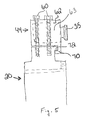
- a brake assembly in accordance with the invention is illustrated having actuator modules 44 radially mounted to the brake head 20 such that the actuator modules 44 can be removed and/or installed radially from the brake head 20 as a unit.
- the brake assembly is substantially similar to the brake assembly described in connection with Figs. 1 and 2 with the exception of the radial mount actuator modules 44.
- the brake head 20 includes a plurality of circumferentially spaced-apart radial mounts 50 to which the actuator modules 44 are securable.
- Each radial mount 50 generally includes a radially extending spline 54 having a radially outer circumferential end face including a module mount surface 56. It will be appreciated that the end face need not be curved, and in fact can be flat or have any other suitable form.
- the mount surface 56 can include mounting holes 58 for receiving a fastener, such as a bolt 60, for securing the actuator module 44 to the brake head 20. Other fasteners can also be used, such as clamps, for example.
- Each actuator module 44 includes a housing 62 for supporting one or more actuator rams 35 and motive devices 63 ( Fig. 5 ) operatively connected to the reciprocating rams 35 for selectively moving the reciprocating ram 35 into and out of forceful engagement with the brake disk stack for applying and releasing braking force.
- the housing 62 further includes housing mounting holes 64 through which bolts 60 extend to secure the actuator module 44 to the brake head 20.
- bolts 60 generally extend radially towards a central axis of the brake head 20 and are accessible from a radially outer circumference of the brake. Thus, access to an end face of the brake head 20 is not necessary to install and/or remove an actuator module 44.
- the brake head 20 can include a recess or protrusion for mating with a corresponding recess or protrusion on each actuator module 44.
- each actuator module 44 includes an undercut lip 70 configured to mate with a protrusion 72 on each radial mount 50.
- the undercut lip 70 can also facilitate load distribution during operation of the actuator modules 44.
- the recesses and protrusions can take a wide variety of forms.
- the actuator modules 44 can also include an electrical connector 74 for coupling with an electrical connector 76 on the brake head 20 for supplying electricity to the actuator modules 44.
- the electrical connectors 74 and 76 can be configured such that a secure electrical connection is made when the actuator modules 44 are mounted to the brake head 20. Accordingly, a secure electrical connection can be made as part of the physical securement of the module 44 to the brake head 20. This feature can eliminate the need to electrically connect the actuator modules 44 in a separate step, and can provide a more secure connection than other methods.
- the actuator modules 44 can be removed from and/or installed on the brake head 20 from a radial direction.
- the bolts 60 can be removed and/or installed from an outer circumference of the brake assembly and, thus, the actuator modules 44 can be removed and/or installed by shifting them radially inwardly/outwardly.
- This configuration eliminates or reduces the need for a module mounting surface parallel to a friction surface of the brake stack thereby tending to reduce the overall weight of the brake.
- the bolts 60 and actuator modules 44 can be installed and removed radially, the need for axial clearance adjacent to the brake head 20 is reduced.
- a brake assembly that enables easy and quick replacement of a malfunctioning electromechanical actuator. No longer must a brake be substantially dissembled to repair a malfunctioning actuator or other actuator identified for repair and/or replacement. Instead, a malfunctioning actuator module 44 (or all of the actuator modules if the malfunctioning module can not be determined) can be removed radially from the brake head 20 simply by removing the fasteners 60 and withdrawing the module 44 radially from the brake head 20. This can be accomplished without having to disassemble the brake disk stack and potentially even with the wheel in place on the axle, as access usually can be gained in most wheel and brake assemblies to the radially outer side of the brake head. As described, to facilitate the easy removal and replacement of the actuator modules, the electrical connectors 74 and 76 can be configured to automatically electrically couple/decouple the actuator modules 44 during installation or removal of the actuator 44.
Landscapes
- Engineering & Computer Science (AREA)
- General Engineering & Computer Science (AREA)
- Mechanical Engineering (AREA)
- Braking Arrangements (AREA)
Applications Claiming Priority (1)
| Application Number | Priority Date | Filing Date | Title |
|---|---|---|---|
| US98785407P | 2007-11-14 | 2007-11-14 |
Publications (1)
| Publication Number | Publication Date |
|---|---|
| EP2060821A1 true EP2060821A1 (fr) | 2009-05-20 |
Family
ID=40409326
Family Applications (1)
| Application Number | Title | Priority Date | Filing Date |
|---|---|---|---|
| EP08169182A Withdrawn EP2060821A1 (fr) | 2007-11-14 | 2008-11-14 | Frein d'avion et procédé doté de modules d'actionnement électromécaniques |
Country Status (2)
| Country | Link |
|---|---|
| US (1) | US20090120739A1 (fr) |
| EP (1) | EP2060821A1 (fr) |
Cited By (3)
| Publication number | Priority date | Publication date | Assignee | Title |
|---|---|---|---|---|
| EP2360072A1 (fr) * | 2010-02-12 | 2011-08-24 | Honeywell International Inc. | Ensemble d'actionnement de frein électrique d'avion doté de frein d'actionneur remplaçable en ligne |
| CN103388635A (zh) * | 2012-05-10 | 2013-11-13 | 梅西耶-布加蒂-道提公司 | 用于飞机轮子的制动器 |
| US8919504B2 (en) | 2009-12-03 | 2014-12-30 | Honeywell International Inc. | Brake actuator assembly with line replaceable motor features |
Families Citing this family (5)
| Publication number | Priority date | Publication date | Assignee | Title |
|---|---|---|---|---|
| IT1395712B1 (it) * | 2009-09-10 | 2012-10-19 | Gaia | Dispositivo e metodo per una rotazione delle ruote dei carrelli di atterraggio di aeromobili |
| FR2954752B1 (fr) * | 2009-12-24 | 2012-03-09 | Messier Bugatti | Ensemble de roue et frein pour aeronef equipe d'un dispositif d'entrainement en rotation. |
| FR2968274B1 (fr) * | 2010-12-06 | 2013-02-01 | Messier Bugatti | Dispositif de freinage/entrainement d'une roue d'aeronef. |
| US9995353B2 (en) * | 2015-12-21 | 2018-06-12 | Goodrich Corporation | Modified actuator design to improve load distribution and damping |
| CN107061560B (zh) * | 2016-12-22 | 2019-03-01 | 西安航空制动科技有限公司 | 一种刹车装置的钢承压盘组件 |
Citations (10)
| Publication number | Priority date | Publication date | Assignee | Title |
|---|---|---|---|---|
| US4381049A (en) | 1979-07-30 | 1983-04-26 | Goodyear Aerospace Corporation | Electrically actuated aircraft brakes |
| US4432440A (en) | 1979-07-30 | 1984-02-21 | Goodyear Aerospace Corporation | Electrically actuated aircraft brakes |
| US4542809A (en) | 1979-07-30 | 1985-09-24 | Goodyear Aerospace Corporation | Electrically actuated aircraft brakes |
| US4567967A (en) | 1979-07-30 | 1986-02-04 | Goodyear Aerospace Corporation | Electrically actuated aircraft brakes |
| US4596316A (en) | 1984-02-10 | 1986-06-24 | Goodyear Aerospace Corporation | Electrically actuated aircraft brakes |
| US4865162A (en) | 1986-12-15 | 1989-09-12 | Opus Acquisition Corporation | Electrically actuated aircraft brakes |
| US6095293A (en) | 1998-02-13 | 2000-08-01 | The B. F. Goodrich Company | Aircraft brake and method with electromechanical actuator modules |
| US20050051390A1 (en) * | 2003-09-09 | 2005-03-10 | Hidetoshi Toyoda | Radially mounted disk brake |
| EP1533536A1 (fr) * | 2003-11-14 | 2005-05-25 | Messier-Bugatti | Atterrisseur, frein pour roue d'aéronef, ensemble de roue freinée d'aréonef, et procédé de maintenance d'un tel atterrisseur |
| US20060042889A1 (en) | 2004-08-31 | 2006-03-02 | Honeywell International Inc. | Brake carrier having improved electromechanical actuator and mounting arrangement therefor |
Family Cites Families (4)
| Publication number | Priority date | Publication date | Assignee | Title |
|---|---|---|---|---|
| GB9005680D0 (en) * | 1990-03-14 | 1990-05-09 | Lucas Ind Plc | Improvements relating to wheels incorporating braking discs |
| DE19621533A1 (de) * | 1996-05-29 | 1997-12-04 | Bosch Gmbh Robert | Elektromotorische Bremsvorrichtung |
| DE19752543A1 (de) * | 1997-11-27 | 1999-06-02 | Bosch Gmbh Robert | Magnetbremse und elektromechanische Bremsvorrichtung mit einer Magnetbremse |
| CA2318688C (fr) * | 1999-09-13 | 2008-11-18 | The B.F. Goodrich Company | Train d'atterrissage comprenant un systeme d'actionnement de frein integre |
-
2008
- 2008-11-14 US US12/271,437 patent/US20090120739A1/en not_active Abandoned
- 2008-11-14 EP EP08169182A patent/EP2060821A1/fr not_active Withdrawn
Patent Citations (10)
| Publication number | Priority date | Publication date | Assignee | Title |
|---|---|---|---|---|
| US4381049A (en) | 1979-07-30 | 1983-04-26 | Goodyear Aerospace Corporation | Electrically actuated aircraft brakes |
| US4432440A (en) | 1979-07-30 | 1984-02-21 | Goodyear Aerospace Corporation | Electrically actuated aircraft brakes |
| US4542809A (en) | 1979-07-30 | 1985-09-24 | Goodyear Aerospace Corporation | Electrically actuated aircraft brakes |
| US4567967A (en) | 1979-07-30 | 1986-02-04 | Goodyear Aerospace Corporation | Electrically actuated aircraft brakes |
| US4596316A (en) | 1984-02-10 | 1986-06-24 | Goodyear Aerospace Corporation | Electrically actuated aircraft brakes |
| US4865162A (en) | 1986-12-15 | 1989-09-12 | Opus Acquisition Corporation | Electrically actuated aircraft brakes |
| US6095293A (en) | 1998-02-13 | 2000-08-01 | The B. F. Goodrich Company | Aircraft brake and method with electromechanical actuator modules |
| US20050051390A1 (en) * | 2003-09-09 | 2005-03-10 | Hidetoshi Toyoda | Radially mounted disk brake |
| EP1533536A1 (fr) * | 2003-11-14 | 2005-05-25 | Messier-Bugatti | Atterrisseur, frein pour roue d'aéronef, ensemble de roue freinée d'aréonef, et procédé de maintenance d'un tel atterrisseur |
| US20060042889A1 (en) | 2004-08-31 | 2006-03-02 | Honeywell International Inc. | Brake carrier having improved electromechanical actuator and mounting arrangement therefor |
Cited By (4)
| Publication number | Priority date | Publication date | Assignee | Title |
|---|---|---|---|---|
| US8919504B2 (en) | 2009-12-03 | 2014-12-30 | Honeywell International Inc. | Brake actuator assembly with line replaceable motor features |
| EP2360072A1 (fr) * | 2010-02-12 | 2011-08-24 | Honeywell International Inc. | Ensemble d'actionnement de frein électrique d'avion doté de frein d'actionneur remplaçable en ligne |
| US9815438B2 (en) | 2010-02-12 | 2017-11-14 | Honeywell International Inc. | Aircraft electric brake actuator assembly with line replaceable actuator brake |
| CN103388635A (zh) * | 2012-05-10 | 2013-11-13 | 梅西耶-布加蒂-道提公司 | 用于飞机轮子的制动器 |
Also Published As
| Publication number | Publication date |
|---|---|
| US20090120739A1 (en) | 2009-05-14 |
Similar Documents
| Publication | Publication Date | Title |
|---|---|---|
| EP2060821A1 (fr) | Frein d'avion et procédé doté de modules d'actionnement électromécaniques | |
| US6662907B1 (en) | Aircraft brake and method with electromechanical actuator modules | |
| EP1766256B1 (fr) | Frein electrique pour aeronef | |
| EP1084949B1 (fr) | Frein multidisques pour avions | |
| US7717240B2 (en) | Electric brake for aircraft | |
| WO1997025548A2 (fr) | Dispositif retenu de freinage pour avion | |
| US8296916B2 (en) | Repair method for electric aircraft brake | |
| US8317001B2 (en) | Electromechanical actuator for a vehicle brake, the vehicle brake including such an actuator, and a method of maintaining such an actuator | |
| CN113291463A (zh) | 转子驱动键组件 | |
| US20050056499A1 (en) | Aircraft brake assembly | |
| WO2005090814A1 (fr) | Frein a disque exterieur a l'enveloppe de frein | |
| CN110195685B (zh) | 刹车系统及外转子式直驱风力发电机组 | |
| WO2005038282A1 (fr) | Procede de remplacement du disque de rotor d'un ensemble frein a disque | |
| EP1626001B1 (fr) | Frein multidisques pour avions | |
| US11226019B2 (en) | Carbon brake stack assembly for improved life | |
| US8794394B2 (en) | Electric brake system with flexible force transfer member |
Legal Events
| Date | Code | Title | Description |
|---|---|---|---|
| PUAI | Public reference made under article 153(3) epc to a published international application that has entered the european phase |
Free format text: ORIGINAL CODE: 0009012 |
|
| AK | Designated contracting states |
Kind code of ref document: A1 Designated state(s): AT BE BG CH CY CZ DE DK EE ES FI FR GB GR HR HU IE IS IT LI LT LU LV MC MT NL NO PL PT RO SE SI SK TR |
|
| AX | Request for extension of the european patent |
Extension state: AL BA MK RS |
|
| 17P | Request for examination filed |
Effective date: 20090704 |
|
| 17Q | First examination report despatched |
Effective date: 20090806 |
|
| AKX | Designation fees paid |
Designated state(s): FR GB |
|
| REG | Reference to a national code |
Ref country code: DE Ref legal event code: 8566 |
|
| STAA | Information on the status of an ep patent application or granted ep patent |
Free format text: STATUS: THE APPLICATION IS DEEMED TO BE WITHDRAWN |
|
| 18D | Application deemed to be withdrawn |
Effective date: 20120619 |