EP2662270A2 - Bicycle light - Google Patents
Bicycle light Download PDFInfo
- Publication number
- EP2662270A2 EP2662270A2 EP13167012.7A EP13167012A EP2662270A2 EP 2662270 A2 EP2662270 A2 EP 2662270A2 EP 13167012 A EP13167012 A EP 13167012A EP 2662270 A2 EP2662270 A2 EP 2662270A2
- Authority
- EP
- European Patent Office
- Prior art keywords
- light
- housing
- led
- reflector
- bicycle
- Prior art date
- Legal status (The legal status is an assumption and is not a legal conclusion. Google has not performed a legal analysis and makes no representation as to the accuracy of the status listed.)
- Granted
Links
Images


Classifications
-
- B—PERFORMING OPERATIONS; TRANSPORTING
- B62—LAND VEHICLES FOR TRAVELLING OTHERWISE THAN ON RAILS
- B62J—CYCLE SADDLES OR SEATS; AUXILIARY DEVICES OR ACCESSORIES SPECIALLY ADAPTED TO CYCLES AND NOT OTHERWISE PROVIDED FOR, e.g. ARTICLE CARRIERS OR CYCLE PROTECTORS
- B62J6/00—Arrangement of optical signalling or lighting devices on cycles; Mounting or supporting thereof; Circuits therefor
- B62J6/01—Electric circuits
- B62J6/015—Electric circuits using electrical power not supplied by the cycle motor generator, e.g. using batteries or piezo elements
-
- B—PERFORMING OPERATIONS; TRANSPORTING
- B62—LAND VEHICLES FOR TRAVELLING OTHERWISE THAN ON RAILS
- B62J—CYCLE SADDLES OR SEATS; AUXILIARY DEVICES OR ACCESSORIES SPECIALLY ADAPTED TO CYCLES AND NOT OTHERWISE PROVIDED FOR, e.g. ARTICLE CARRIERS OR CYCLE PROTECTORS
- B62J6/00—Arrangement of optical signalling or lighting devices on cycles; Mounting or supporting thereof; Circuits therefor
- B62J6/02—Headlights
- B62J6/028—Headlights specially adapted for rider-propelled cycles with or without additional source of power
- B62J6/029—Headlights specially adapted for rider-propelled cycles with or without additional source of power characterised by the structure, e.g. casings
-
- B—PERFORMING OPERATIONS; TRANSPORTING
- B62—LAND VEHICLES FOR TRAVELLING OTHERWISE THAN ON RAILS
- B62J—CYCLE SADDLES OR SEATS; AUXILIARY DEVICES OR ACCESSORIES SPECIALLY ADAPTED TO CYCLES AND NOT OTHERWISE PROVIDED FOR, e.g. ARTICLE CARRIERS OR CYCLE PROTECTORS
- B62J6/00—Arrangement of optical signalling or lighting devices on cycles; Mounting or supporting thereof; Circuits therefor
- B62J6/02—Headlights
- B62J6/028—Headlights specially adapted for rider-propelled cycles with or without additional source of power
- B62J6/03—Supporting means therefor, e.g. mounting brackets
Definitions
- This invention concerns bicycle lights attachable to a bicycle (e.g. to handlebars) or to a rider's helmet.
- the invention concerns a bicycle light of efficient and compact configuration, producing both spot and flood lighting and preferably with side lights.
- Front and rear bicycle lights have been available in many different forms. Front bike lights have been provided for attachment to handlebars and to helmets, have been self-contained with battery or wired to a separately mounted battery. The front lights typically have several modes of operation, i.e. steady or flashing, and sometimes have ability to adjust brightness. Some have switched on automatically with darkness. Side lights have been included on a few of them. Many models of front lights have been offered by Planet, Cygolite, Busch & Mueller, NightRider, Cat Eye, Knog, and Light & Motion.
- Some bicycle lights have provided light projection with fill light around a spot beam, useful for illuminating trails.
- Light & Motion's SECA light had upper deep biconic reflectors and lower shallower reflectors behind a single curved front face. The challenges with that design was the difficulty in creating a curved face that is optically clean.
- the optimum beam pattern for a bike light has a deep-penetrating spot beam down the center, with fill light to the sides to illuminate trail edges while allowing the rider to see far down the trail.
- An efficient way to achieve this beam pattern, in accordance with the invention, is with reflector cones, which requires two reflector cones, one to essentially collimate light from one or more LEDs, and the other to direct LED light more widely as a flood beam, at a wide enough angle to fill in the sides of the trail for a bike rider.
- An efficient spot beam generator must be a deep cone or parabolic reflector receiving and projecting the light of one or more LEDs.
- the deep spot and wider angle beams are positioned one above the other, so that the deeper reflector cone extends from an LED circuit board farther forward than the adjacent shallow, wider-angle reflector.
- the two reflectors are positioned closely adjacent to one another, preferably formed in the same component.
- a window plate of the housing, just forward of the reflector component, is angled with respect to vertical (and with respect to the LED circuit board), affording greater depth as needed for the spot beam reflector and lesser depth as needed for the flood reflector.
- the spot beam is above the flood beam, so that the window plate angles downwardly, preferably about 12 ⁇ with respect to vertical or with respect to the LED circuit board.
- the angle should be at least 7 ⁇ , more preferably at least about 10 ⁇ ; and optimally 12 ⁇ to 15 ⁇ .
- side lights provided on the light housing, preferably amber light, for safety in traffic.
- These side lights may comprise amber lenses or windows, fed by one or more LEDs separate from the spot and flood LEDs (or the lenses can be clear and colorless, with the side LEDs being color LEDs).
- An important feature of the front light of the invention is a separate switch for the side lights, to optionally switch them off when not needed, such as on a trail.
- a second switch is provided, serving under the main switch, so that the side lights cannot be activated without the main lights, but while the main lights are operating, the side lights can be on, or switched to a pulse mode, or off.
- Figure 1 shows a front bicycle light 10 of the invention, with a housing or casing 12 on which are mounted push button type switches 14 and 16, preferably at a top side as shown.
- a connector bracket 18 is seen secured to the bottom side of the light casing 12.
- this connector has a handlebar-engaging surface 20, appropriately curved as shown, and a connection point 22 for a flexible, stretchable strap to be wrapped tightly around the bottom of the handlebar and secured back to the connector device 18.
- Other forms of connection to a bicycle can be used.
- Left and right side lights 24 are included in a preferred embodiment of the front light of the invention. These project yellow or amber light, but other colors are also possible.
- the front end 26 of the bicycle light is angled downwardly, as described above.
- the downward angle is relative to vertical or with respect to a plane indicated at 28 and defined by a decorative circumferential groove as shown (the plane being perpendicular to the length of the casing 12). This downward angle is also relative to an LED circuit board, described below.
- the bicycle light assembly 10 has an internal LED circuit board 30 supporting, in this preferred embodiment, two upper LEDs 32 and a lower LED 34, with some of the LED driver electronics indicated at 36.
- the LED board 30 is mounted essentially vertically within the casing 12, that is, essentially perpendicular to the direction of light projection from the head lamp 10. As explained above, however, other components are angled downwardly, including a multi-cone LED light reflector 38, a transparent window or port 40, and a snapped-in securing bezel 42.
- the reason for this angled relationship is to accommodate the required deeper reflectors for the upper LEDs 32, which form a spot beam for deeper penetration into the darkness along a trail, and a shallower reflector as required for the lower LED 34, which produces a wider flood beam.
- the angling of the front face of the head lamp device conserves space and total size and volume of the device, while efficiently providing for spot and flood beams.
- FIG 2A shows the casing 12 exploded, revealing a preferred construction with the casing being assembled from a metal housing component 12a and a plastic housing component 12b, the latter carrying the push button switch activators 14 and 16 and receiving a battery (shown in Figure 4 ).
- the metal housing component 12a dissipates heat.
- Figure 3 shows the assembled bicycle head lamp 10 in a frontal view.
- the integrated reflector block 38 is shown, with its three reflector cones 38a and 38b, in position to produce the spot beam from the LEDs 32 and the flood beam from the LED 24.
- the word "cone” is used to mean a reflector of an effective shape to produce the beam desired, typically a parabolic reflector, not usually in the shape of a true cone.
- the reflector device 38 is preferably a single unit with the three reflectors, and it can be produced of metallized molded plastic.
- the bottom reflector 38b may be greater in width than height, to produce the desired wide flood beam to illuminate a wide area in front of the rider, including the sides of a trail.
- Figure 3 shows that the headlamp casing 12, at its front end 26 and preferably also through its length, is elliptical or oblong in cross section, although it could be other shapes, including circular.
- Figure 3 also shows the snapped-in securing bezel 42, a top clip 42a, and legs or standoffs 40a that are integral with the window 40 to position the window correctly (see Figure 4 ).
- FIG 4 shows the bicycle head lamp 10 in side elevational section as seen along the midline.
- the casing or housing 12 contains a relative large battery 44, preferably a rechargeable battery, chargeable via a charging port 46, which can be a micro USB port, protected by a removable cover 48.
- a relative large battery 44 preferably a rechargeable battery
- chargeable via a charging port 46 which can be a micro USB port
- a removable cover 48 Also shown are the two switches 14 and 16 that are included in a preferred embodiment.
- the switch 14 is a main switch, which will turn on the spot and flood lights together, with additional pushes of the switch providing a different light level or a pulsing mode, and also switching off the head lamp. Operation of the switch 16 requires that the main switch 14 be on at one of its settings; the switch 16 operates the side lights indicated at 24 in Figures 1 and 2 and also shown in Figure 5 .
- the external push-button switches 14 and 16 operate momentary switches 14a, 16a inside the housing, these being connected on a switch circuit board 50 which connects with the battery 44 and with the LED board 30, and supports some of the LED driver electronics.
- a connector from the PC board 50 to the LED board is shown at 51.
- the LED driver requires some space, and the components that heat up most are on the LED PCB 30 for best heat dissipation as explained below.
- Figure 4 also shows that the LED circuit board 30 is secured to a metal heat sink block 52 via machine screws 54 (only one of which is visible in Figure 4 ), the block 52 being in heat conducting contact with the metal exterior portion 12a of the casing and with a mounting base 55 (with which the block 52 preferably is integral), which connects to the connector bracket 18. This dissipates heat from the battery and particularly from the LED board 30.
- a plastic rib 56 is seen below and supporting the battery 44.
- Figure 4 shows the multi-cone reflector 38. Since this cross section is taken through the midline of the head lamp device, a shared wall 60 of the two top reflectors 38a is seen, indicated in cross section. The lower LED 34 is visible in cross section, but the upper LEDs 38a are not seen in Figure 4 . Just left of the junction area 60 in Figure 4 is seen the exterior of the left-side reflector 38a.
- Figure 4 shows the end profile of the front 26 of the housing as an inwardly curving line 26a. This is a decorative feature by which the front end sweeps concavely inwardly at left and right.
- Figure 5 shows the bicycle light 10 in a cross section taken on a horizontal plane approximately at mid-level through the housing, at the level of the side lights 24 seen in Figure 1 .
- the side light structures 24 are each light pipes/lenses to carry light from internal LEDs 62 to the sides of the head lamp.
- Each side light LED 62 is preferably mounted on the back side of the LED board 30.
- the light pipes/lenses 24 could be amber colored with the LED producing approximately white light, preferably the LEDs have the yellow or amber color, with the light pipes/lenses 24 being clear, essentially without color.
- FIGS 6 and 7 show a modified embodiment of the bicycle light 70 of the invention.
- the light structure 70 is similar to the light 10 of the first embodiment, having upper and lower LEDs 32 and 34 on a common printed circuit board (not shown), oriented generally upright in the housing 12a, and with a reflector structure 38c which again has a lower, shallower reflector cone 38d for wide angle beam projection.
- the lower reflector cone 38d not being as deep as the spot reflector cones 38e above, does not protrude as far forward at the front of the light housing, thus being receded with respect to the reflector cones 38e.
- the front window 72 of the light assembly is not a sloped single plane but instead has two separate planar sections, an upper part which is a plane 72a and which may be essentially vertical and perpendicular to the light path, and a lower part which is a plane 72b which is sloped back, to conform to the receded lower reflector 38d surface.
- the window 72 can be a single plastic molding comprising the two separate planes 72a and 72b.
- the light assembly 70 is similar to that described above, especially with regard to internal components.
- the LED circuit board (not shown) is vertical or approximately vertical, essentially perpendicular to the light path.
- the reflector block 38c is similar to that shown in Figure 4 but with the upper portion having an essentially vertically oriented front and the lower portion being angled or recessed to recede as described above.
- the angle of this lower portion can be in the range of about 15 ⁇ to 30 ⁇ . When angles are described herein as "about” a specific number of degrees, this should be considered as including a range of ten percent above and below that figure.
Landscapes
- Engineering & Computer Science (AREA)
- Mechanical Engineering (AREA)
- Non-Portable Lighting Devices Or Systems Thereof (AREA)
- Arrangement Of Elements, Cooling, Sealing, Or The Like Of Lighting Devices (AREA)
Abstract
Description
- This invention concerns bicycle lights attachable to a bicycle (e.g. to handlebars) or to a rider's helmet. In particular the invention concerns a bicycle light of efficient and compact configuration, producing both spot and flood lighting and preferably with side lights.
- Front and rear bicycle lights have been available in many different forms. Front bike lights have been provided for attachment to handlebars and to helmets, have been self-contained with battery or wired to a separately mounted battery. The front lights typically have several modes of operation, i.e. steady or flashing, and sometimes have ability to adjust brightness. Some have switched on automatically with darkness. Side lights have been included on a few of them. Many models of front lights have been offered by Planet, Cygolite, Busch & Mueller, NightRider, Cat Eye, Knog, and Light & Motion.
- Some bicycle lights have provided light projection with fill light around a spot beam, useful for illuminating trails. Light & Motion's SECA light had upper deep biconic reflectors and lower shallower reflectors behind a single curved front face. The challenges with that design was the difficulty in creating a curved face that is optically clean.
- However, in available bicycle lights prior to this invention there has not been a compact and efficient front light providing spot and flood beams, with efficient optics and with optional side lights, as in the bicycle light described below.
- As explained above, the optimum beam pattern for a bike light has a deep-penetrating spot beam down the center, with fill light to the sides to illuminate trail edges while allowing the rider to see far down the trail. An efficient way to achieve this beam pattern, in accordance with the invention, is with reflector cones, which requires two reflector cones, one to essentially collimate light from one or more LEDs, and the other to direct LED light more widely as a flood beam, at a wide enough angle to fill in the sides of the trail for a bike rider. An efficient spot beam generator must be a deep cone or parabolic reflector receiving and projecting the light of one or more LEDs. However, for flood light, or fill light, a shallower reflector cone is needed (the flood reflector could also be deep, but if so must spread widely so as to require additional total area at the front end of the light). In the compact and efficient construction of the current invention the deep spot and wider angle beams are positioned one above the other, so that the deeper reflector cone extends from an LED circuit board farther forward than the adjacent shallow, wider-angle reflector. The two reflectors are positioned closely adjacent to one another, preferably formed in the same component. A window plate of the housing, just forward of the reflector component, is angled with respect to vertical (and with respect to the LED circuit board), affording greater depth as needed for the spot beam reflector and lesser depth as needed for the flood reflector. Preferably the spot beam is above the flood beam, so that the window plate angles downwardly, preferably about 12□ with respect to vertical or with respect to the LED circuit board. The angle should be at least 7□, more preferably at least about 10□; and optimally 12□ to 15□.
- Another feature of the invention is side lights provided on the light housing, preferably amber light, for safety in traffic. These side lights may comprise amber lenses or windows, fed by one or more LEDs separate from the spot and flood LEDs (or the lenses can be clear and colorless, with the side LEDs being color LEDs). An important feature of the front light of the invention is a separate switch for the side lights, to optionally switch them off when not needed, such as on a trail. A second switch is provided, serving under the main switch, so that the side lights cannot be activated without the main lights, but while the main lights are operating, the side lights can be on, or switched to a pulse mode, or off.
- It is among the objects of the invention to provide a front bicycle light with an optimum beam pattern while also providing for efficient use of the light either in traffic or on a trail. These and other objects, advantages and features of the invention will be apparent from the following description of a preferred embodiment, considered along with the accompanying drawings.
-
-
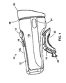
Figure 1 is a perspective view showing a bicycle light according to the invention. -
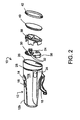
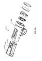
Figure 2 is an exploded perspective view showing the bicycle light. -
Figure 2A is another exploded view. -
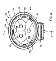
Figure 3 is a frontal view showing components of the bicycle light. -
Figure 4 is a side elevation view in section, as seen along the plane 4-4 inFigure 3 , showing internal components of the assembled bicycle light. -
Figure 5 is a detailed view in top plan section showing components of side lights of the device. -
Figures 6 and 7 are front and perspective views showing another embodiment of the bicycle light of the invention. -
Figure 1 shows afront bicycle light 10 of the invention, with a housing orcasing 12 on which are mounted pushbutton type switches - A
connector bracket 18 is seen secured to the bottom side of thelight casing 12. In a preferred form this connector has a handlebar-engaging surface 20, appropriately curved as shown, and aconnection point 22 for a flexible, stretchable strap to be wrapped tightly around the bottom of the handlebar and secured back to theconnector device 18. Other forms of connection to a bicycle can be used. - Left and
right side lights 24 are included in a preferred embodiment of the front light of the invention. These project yellow or amber light, but other colors are also possible. - The
front end 26 of the bicycle light is angled downwardly, as described above. The downward angle is relative to vertical or with respect to a plane indicated at 28 and defined by a decorative circumferential groove as shown (the plane being perpendicular to the length of the casing 12). This downward angle is also relative to an LED circuit board, described below. - As indicated in the partially exploded view of
Figure 2 , thebicycle light assembly 10 has an internalLED circuit board 30 supporting, in this preferred embodiment, twoupper LEDs 32 and alower LED 34, with some of the LED driver electronics indicated at 36. TheLED board 30 is mounted essentially vertically within thecasing 12, that is, essentially perpendicular to the direction of light projection from thehead lamp 10. As explained above, however, other components are angled downwardly, including a multi-coneLED light reflector 38, a transparent window orport 40, and a snapped-in securingbezel 42. The reason for this angled relationship is to accommodate the required deeper reflectors for theupper LEDs 32, which form a spot beam for deeper penetration into the darkness along a trail, and a shallower reflector as required for thelower LED 34, which produces a wider flood beam. The angling of the front face of the head lamp device conserves space and total size and volume of the device, while efficiently providing for spot and flood beams. -
Figure 2A shows thecasing 12 exploded, revealing a preferred construction with the casing being assembled from ametal housing component 12a and aplastic housing component 12b, the latter carrying the pushbutton switch activators Figure 4 ). Themetal housing component 12a dissipates heat. -
Figure 3 shows the assembledbicycle head lamp 10 in a frontal view. The integratedreflector block 38 is shown, with its threereflector cones LEDs 32 and the flood beam from theLED 24. The word "cone" is used to mean a reflector of an effective shape to produce the beam desired, typically a parabolic reflector, not usually in the shape of a true cone. Thereflector device 38 is preferably a single unit with the three reflectors, and it can be produced of metallized molded plastic. Thebottom reflector 38b may be greater in width than height, to produce the desired wide flood beam to illuminate a wide area in front of the rider, including the sides of a trail.Figure 3 shows that theheadlamp casing 12, at itsfront end 26 and preferably also through its length, is elliptical or oblong in cross section, although it could be other shapes, including circular. -
Figure 3 also shows the snapped-in securingbezel 42, a top clip 42a, and legs orstandoffs 40a that are integral with thewindow 40 to position the window correctly (seeFigure 4 ). -
Figure 4 shows thebicycle head lamp 10 in side elevational section as seen along the midline. The casing orhousing 12 contains a relativelarge battery 44, preferably a rechargeable battery, chargeable via a chargingport 46, which can be a micro USB port, protected by aremovable cover 48. Also shown are the twoswitches switch 14 is a main switch, which will turn on the spot and flood lights together, with additional pushes of the switch providing a different light level or a pulsing mode, and also switching off the head lamp. Operation of theswitch 16 requires that themain switch 14 be on at one of its settings; theswitch 16 operates the side lights indicated at 24 inFigures 1 and2 and also shown inFigure 5 . This gives the bike rider the option to use side lighting for urban riding, but to switch off the side lights when riding on trails. Additional settings such as flashing of the side lights can also be provided. The external push-button switches momentary switches switch circuit board 50 which connects with thebattery 44 and with theLED board 30, and supports some of the LED driver electronics. A connector from thePC board 50 to the LED board is shown at 51. The LED driver requires some space, and the components that heat up most are on theLED PCB 30 for best heat dissipation as explained below. -
Figure 4 also shows that theLED circuit board 30 is secured to a metalheat sink block 52 via machine screws 54 (only one of which is visible inFigure 4 ), theblock 52 being in heat conducting contact with themetal exterior portion 12a of the casing and with a mounting base 55 (with which theblock 52 preferably is integral), which connects to theconnector bracket 18. This dissipates heat from the battery and particularly from theLED board 30. InFigure 4 aplastic rib 56 is seen below and supporting thebattery 44. - At the front end of the
head lamp 10,Figure 4 shows themulti-cone reflector 38. Since this cross section is taken through the midline of the head lamp device, a sharedwall 60 of the twotop reflectors 38a is seen, indicated in cross section. Thelower LED 34 is visible in cross section, but theupper LEDs 38a are not seen inFigure 4 . Just left of thejunction area 60 inFigure 4 is seen the exterior of the left-side reflector 38a. -
Figure 4 shows the end profile of thefront 26 of the housing as an inwardly curvingline 26a. This is a decorative feature by which the front end sweeps concavely inwardly at left and right. -
Figure 5 shows thebicycle light 10 in a cross section taken on a horizontal plane approximately at mid-level through the housing, at the level of the side lights 24 seen inFigure 1 . The sidelight structures 24 are each light pipes/lenses to carry light frominternal LEDs 62 to the sides of the head lamp. Eachside light LED 62 is preferably mounted on the back side of theLED board 30. Although the light pipes/lenses 24 could be amber colored with the LED producing approximately white light, preferably the LEDs have the yellow or amber color, with the light pipes/lenses 24 being clear, essentially without color. -
Figures 6 and 7 show a modified embodiment of thebicycle light 70 of the invention. Thelight structure 70 is similar to the light 10 of the first embodiment, having upper andlower LEDs housing 12a, and with areflector structure 38c which again has a lower,shallower reflector cone 38d for wide angle beam projection. Thelower reflector cone 38d, not being as deep as thespot reflector cones 38e above, does not protrude as far forward at the front of the light housing, thus being receded with respect to thereflector cones 38e. The difference from the earlier embodiment is that thefront window 72 of the light assembly is not a sloped single plane but instead has two separate planar sections, an upper part which is aplane 72a and which may be essentially vertical and perpendicular to the light path, and a lower part which is aplane 72b which is sloped back, to conform to the recededlower reflector 38d surface. Thewindow 72 can be a single plastic molding comprising the twoseparate planes - In other respects the
light assembly 70 is similar to that described above, especially with regard to internal components. The LED circuit board (not shown) is vertical or approximately vertical, essentially perpendicular to the light path. Thereflector block 38c is similar to that shown inFigure 4 but with the upper portion having an essentially vertically oriented front and the lower portion being angled or recessed to recede as described above. The angle of this lower portion can be in the range of about 15□ to 30□. When angles are described herein as "about" a specific number of degrees, this should be considered as including a range of ten percent above and below that figure.
Claims (16)
- A bicycle light, comprising:a light housing,a connector on the housing for securing the bicycle light to a bicycle or to a user,a battery contained within the housing,an LED circuit board within the housing, and including an external switch on the housing for providing power from the battery to the LED circuit board when desired, the LED circuit board being essentially planar and containing at least one LED in an upper part of the board and at least one LED in a lower part of the board, both LEDs directed toward a front end of the housing,reflectors positioned in the housing directly in front of the LED circuit board to reflect light from the LEDs in a forward direction out the front of the housing, the reflector at the upper LED being a deep reflector producing a spot beam and the reflector at the lower LED being a shallow reflector, shallower than the deep reflector and extending forward less than the deep reflector and configured to project flood light out through the front of the housing, anda front port or window in the housing including a transparent window plate sealed in the housing, at least a part of the window plate being planar and angled obliquely downwardly relative to the LED circuit board and relative to the direction of projection of light from the LEDs, such that a lower part of the window plate is receded farther back than an upper part of the window plate, so as to provide greater depth of space in the housing for the deeper reflector in the upper part of the housing and lesser depth of space for the shallow reflector in the lower part of the housing.
- The bicycle light of claim 1, wherein the window plate upper part is essentially vertical and the window plate lower part is angled.
- The bicycle light of claim 2, wherein the window plate lower part is angled about 15□ from vertical.
- The bicycle light of claim 2, wherein the window plate is an integrally formed plastic molding.
- The bicycle light of claim 1, wherein the window plate defines a single plane.
- The bicycle light of claim 5, wherein the window plate is angled at least about 7□, preferably about 10□and most preferably about 12□ from the planar LED circuit board.
- The bicycle light of claim 1, wherein the deep reflector at the upper LED is one of: a parabolic reflector; or a biconic reflector.
- The bicycle light of claim 1, with two LEDs in the upper part of the circuit board, a said deep reflector being provided for each of the upper LEDs.
- The bicycle light of claim 1, wherein the battery is a rechargeable battery, and the housing including a micro USB charging port for recharging the battery.
- The bicycle light of claim 1, further including left and right side lights on the housing, the side lights producing amber light.
- The bicycle light of claim 1, wherein the deep reflector at the upper LED is a parabolic reflector and wherein the side lights include at least one side light LED, including a second switch on the housing, independently controlling the side light LED so that the side lights need not be on when the forward-projecting lights are on.
- The bicycle light of claim 1, wherein the deep reflector at the upper LED is a biconic reflector and wherein the side light LED is mounted on the LED circuit board.
- A bicycle light, comprising:a light housing,a connector on the housing for securing the bicycle light to a bicycle or to a user,a battery contained within the housing,an LED circuit board within the housing, and including an external switch on the housing for providing power from the battery to the LED circuit board when desired, the LED circuit board containing at least one LED directed toward a front end of the housing,a reflector positioned in the housing directly in front of the LED circuit board to reflect light from the LED in a forward direction out the front of the housing,a side light LED in the housing and side light means for directing light from the side light LED to side light windows at left and right on the housing, for side lights, anda second switch on the housing, independently controlling the side light LED so that the side lights need not be on when the forward-projecting lights are on.
- The bicycle light of claim 13, wherein the side light means comprises light pipes from the side light LED to the side light windows.
- The bicycle light of claim 13, wherein the side light LED is mounted on a back side of the LED circuit board.
- The bicycle light of claim 13, wherein the light housing comprises two parts, a front metal part and a rear plastic part, the rear part containing the battery and sliding into the front part as assembled, the external switch being supported on the plastic part and the metal part serving to dissipate heat to exterior of the bicycle light.
Applications Claiming Priority (1)
| Application Number | Priority Date | Filing Date | Title |
|---|---|---|---|
| US13/470,178 US8974098B2 (en) | 2012-05-11 | 2012-05-11 | Bicycle light |
Publications (3)
| Publication Number | Publication Date |
|---|---|
| EP2662270A2 true EP2662270A2 (en) | 2013-11-13 |
| EP2662270A3 EP2662270A3 (en) | 2014-02-12 |
| EP2662270B1 EP2662270B1 (en) | 2020-08-05 |
Family
ID=48444076
Family Applications (1)
| Application Number | Title | Priority Date | Filing Date |
|---|---|---|---|
| EP13167012.7A Not-in-force EP2662270B1 (en) | 2012-05-11 | 2013-05-08 | Bicycle light |
Country Status (3)
| Country | Link |
|---|---|
| US (2) | US8974098B2 (en) |
| EP (1) | EP2662270B1 (en) |
| DK (1) | DK2662270T3 (en) |
Cited By (2)
| Publication number | Priority date | Publication date | Assignee | Title |
|---|---|---|---|---|
| WO2017017396A1 (en) * | 2015-07-29 | 2017-02-02 | Karbon Kinetics Limited | Handlebar mountable light pipe apparatus for a bicycle |
| SE2250899A1 (en) * | 2022-07-12 | 2024-01-13 | Bookman Ab | A bicycle light device |
Families Citing this family (23)
| Publication number | Priority date | Publication date | Assignee | Title |
|---|---|---|---|---|
| TWM431073U (en) * | 2012-03-03 | 2012-06-11 | Yi-Ping Lin | Bidirectional light-emitting illumination device for wheel rim |
| USD746501S1 (en) * | 2013-02-08 | 2015-12-29 | Planet Bike, LLC | Bicycle light |
| EP2826699A1 (en) * | 2013-07-17 | 2015-01-21 | Fast Field Industrial Limited | A portable light for a bicycle |
| US20150197299A1 (en) * | 2014-01-13 | 2015-07-16 | Specialized Bicycle Components, Inc. | Bicycle taillight with parallel lighting element |
| USD735381S1 (en) * | 2014-03-17 | 2015-07-28 | Wen-Sung Lee | Bicycle lamp |
| DE102014004698B3 (en) * | 2014-03-31 | 2015-08-06 | Matthias Ebel | Lighting for an at least partially human-powered vehicle or its trailer by means of light guide elements, controlled by a mobile terminal or smartphone or by a central light source |
| USD756027S1 (en) * | 2014-07-23 | 2016-05-10 | SSB Design, Inc. | Light for cycling |
| USD751739S1 (en) * | 2014-08-29 | 2016-03-15 | SSB Design, Inc. | Cycling headlight |
| USD753333S1 (en) * | 2014-08-29 | 2016-04-05 | SSB Design, Inc. | LEDs for cycling headlight |
| US9604125B2 (en) * | 2014-12-22 | 2017-03-28 | Shredlife, Inc. | Accessory mounting assembly for skateboards |
| USD759859S1 (en) | 2014-12-30 | 2016-06-21 | Energizer Brands, Llc | Bicycle lighting unit |
| USD759860S1 (en) | 2014-12-30 | 2016-06-21 | Energizer Brands, Llc | Bicycle lighting unit |
| USD783188S1 (en) * | 2015-07-15 | 2017-04-04 | EarthSpirits Net Inc. | Bicycle headlight |
| AU2017269239A1 (en) | 2016-05-21 | 2019-01-03 | JST Performance, LLC | Method and apparatus for vehicular light fixtures |
| US10131392B2 (en) * | 2016-10-21 | 2018-11-20 | Light & Motion Industries | Rechargeable bicycle light system |
| US10766554B1 (en) * | 2016-10-21 | 2020-09-08 | Light & Motion Industries | Compact, waterproof rechargeable light assembly |
| WO2018144091A2 (en) * | 2016-11-03 | 2018-08-09 | Sinewave Inc. | Bicycle light |
| USD865252S1 (en) | 2018-05-23 | 2019-10-29 | Annex Products Pty. Ltd. | Charge light |
| WO2021112289A1 (en) * | 2019-12-05 | 2021-06-10 | 이재용 | Light for bike |
| US11040748B1 (en) | 2020-08-19 | 2021-06-22 | Dirk Steyn | Bicycle headlight with linear LED devices and related methods |
| GB202020323D0 (en) * | 2020-12-22 | 2021-02-03 | Sparrow Roger Lionel David | Bicycle light |
| US11155315B1 (en) * | 2021-01-29 | 2021-10-26 | Jetson Electric Bike LLC | Bicycle frame lighting system |
| USD1014802S1 (en) * | 2021-11-22 | 2024-02-13 | Dongguan Wate Electronic Technology Co., Ltd. | Bicycle headlight |
Family Cites Families (19)
| Publication number | Priority date | Publication date | Assignee | Title |
|---|---|---|---|---|
| US2521251A (en) * | 1948-10-25 | 1950-09-05 | Doyt L Pettit | Sight tube for lamps |
| GB1187846A (en) * | 1966-06-06 | 1970-04-15 | Cibie Projecteurs | A Headlamp Comprising a Double Reflector, for Vehicles in particular. |
| JPS5963909U (en) * | 1982-10-22 | 1984-04-27 | 株式会社津山金属製作所 | Lighting equipment for bicycles, etc. |
| US5077644A (en) * | 1989-08-25 | 1991-12-31 | Rayovac Corporation | Reflector for hand held flashlight |
| US5567036A (en) * | 1995-04-05 | 1996-10-22 | Grote Industries, Inc. | Clearance and side marker lamp |
| DE19941987A1 (en) * | 1999-09-03 | 2001-03-08 | Zweibrueder Stahlwarenkontor G | Torch has first light source, hollow reflector in housing, high power LED on annular casing of lamp head whose light cone is radiated essentially in radial direction with respect to lamp head |
| JP4070494B2 (en) * | 2002-04-03 | 2008-04-02 | 三洋電機株式会社 | Bicycle headlight |
| EP1514054B1 (en) * | 2002-06-20 | 2017-10-18 | Energizer Brands, LLC | Led lighting device |
| US6840654B2 (en) * | 2002-11-20 | 2005-01-11 | Acolyte Technologies Corp. | LED light and reflector |
| JP4061347B2 (en) * | 2003-08-05 | 2008-03-19 | 株式会社キャットアイ | Lighting device |
| US7387402B1 (en) * | 2003-11-13 | 2008-06-17 | Lui Phillip Chun Wai | Multiple light LED flashlight |
| DE102005052179A1 (en) * | 2005-10-24 | 2007-05-03 | Stefan Golla | Optimized LED bicycle lamp reflector |
| US7281820B2 (en) * | 2006-01-10 | 2007-10-16 | Bayco Products, Ltd. | Lighting module assembly and method for a compact lighting device |
| TWM333518U (en) * | 2007-10-12 | 2008-06-01 | Dosun Solar Technology Co Ltd | The LED lamps and lanterns with two illumination areas |
| US7896518B2 (en) * | 2008-01-22 | 2011-03-01 | Powertech, Inc. | Multimode flashlight having light emitting diodes |
| US8325027B2 (en) * | 2009-05-08 | 2012-12-04 | Lightlane Llc | Safety light device |
| US8366293B2 (en) * | 2009-06-22 | 2013-02-05 | Mcdermott Damien | Color changing lighting device |
| CN201680161U (en) * | 2010-03-25 | 2010-12-22 | 戴向阳 | LED work light convenient for installation |
| JP5285038B2 (en) * | 2010-08-31 | 2013-09-11 | シャープ株式会社 | Light projecting structure and lighting device |
-
2012
- 2012-05-11 US US13/470,178 patent/US8974098B2/en not_active Ceased
-
2013
- 2013-05-08 DK DK13167012.7T patent/DK2662270T3/en active
- 2013-05-08 EP EP13167012.7A patent/EP2662270B1/en not_active Not-in-force
-
2017
- 2017-03-10 US US15/456,343 patent/USRE47688E1/en not_active Expired - Fee Related
Non-Patent Citations (1)
| Title |
|---|
| None |
Cited By (6)
| Publication number | Priority date | Publication date | Assignee | Title |
|---|---|---|---|---|
| WO2017017396A1 (en) * | 2015-07-29 | 2017-02-02 | Karbon Kinetics Limited | Handlebar mountable light pipe apparatus for a bicycle |
| CN108349560A (en) * | 2015-07-29 | 2018-07-31 | 卡尔邦动力有限公司 | Handlebar-mountable light tube unit for bicycles |
| US10189523B2 (en) | 2015-07-29 | 2019-01-29 | Karbon Kinetics Limited | Handlebar mountable light pipe apparatus for a bicycle |
| SE2250899A1 (en) * | 2022-07-12 | 2024-01-13 | Bookman Ab | A bicycle light device |
| WO2024015004A1 (en) * | 2022-07-12 | 2024-01-18 | Bookman Ab | A bicycle light device |
| SE546478C2 (en) * | 2022-07-12 | 2024-11-12 | Bookman Ab | A bicycle light device |
Also Published As
| Publication number | Publication date |
|---|---|
| DK2662270T3 (en) | 2020-11-09 |
| EP2662270B1 (en) | 2020-08-05 |
| US8974098B2 (en) | 2015-03-10 |
| USRE47688E1 (en) | 2019-11-05 |
| EP2662270A3 (en) | 2014-02-12 |
| US20130301285A1 (en) | 2013-11-14 |
Similar Documents
| Publication | Publication Date | Title |
|---|---|---|
| USRE47688E1 (en) | Bicycle light | |
| AU2020273363B2 (en) | Prismatic LED assembly for luminaire | |
| USD677417S1 (en) | Retrofit LED luminaire | |
| AU2012246705B2 (en) | Headlamp assembly with planar heat sink structure | |
| EP3192728B1 (en) | Bicycle light | |
| GB2522108A (en) | Bicycle taillight with parallel lighting element | |
| JP2014239069A (en) | Lighting device and method for fire fighter | |
| JP2007535093A (en) | Lighted headwear | |
| NZ552414A (en) | Lighting apparatus in the visor of a hat | |
| US11906147B2 (en) | Illumination devices | |
| JP2016503366A (en) | Bicycle projector with laser beam | |
| TW201242812A (en) | Composite fog light device with daytime running light function | |
| JP3176119U (en) | Bicycle tail lamp | |
| TWI545037B (en) | Composite lights | |
| US12510225B2 (en) | Illumination devices | |
| TWM446723U (en) | Fog light | |
| CN220379520U (en) | Light emitting device | |
| GB2490371A (en) | Lamp device | |
| CN211568178U (en) | Motorcycle spotlight | |
| CN211875911U (en) | Lighting device and scooter | |
| KR200472472Y1 (en) | Side corner lamp | |
| RU2682316C1 (en) | Mine head lamp | |
| KR101295640B1 (en) | Portable flash | |
| CN120753462A (en) | Safety helmet earmuff and safety protection assembly | |
| TWM495319U (en) | Composite lamp for vehicle |
Legal Events
| Date | Code | Title | Description |
|---|---|---|---|
| PUAI | Public reference made under article 153(3) epc to a published international application that has entered the european phase |
Free format text: ORIGINAL CODE: 0009012 |
|
| AK | Designated contracting states |
Kind code of ref document: A2 Designated state(s): AL AT BE BG CH CY CZ DE DK EE ES FI FR GB GR HR HU IE IS IT LI LT LU LV MC MK MT NL NO PL PT RO RS SE SI SK SM TR |
|
| AX | Request for extension of the european patent |
Extension state: BA ME |
|
| PUAL | Search report despatched |
Free format text: ORIGINAL CODE: 0009013 |
|
| AK | Designated contracting states |
Kind code of ref document: A3 Designated state(s): AL AT BE BG CH CY CZ DE DK EE ES FI FR GB GR HR HU IE IS IT LI LT LU LV MC MK MT NL NO PL PT RO RS SE SI SK SM TR |
|
| AX | Request for extension of the european patent |
Extension state: BA ME |
|
| RIC1 | Information provided on ipc code assigned before grant |
Ipc: B62J 6/02 20060101ALI20140109BHEP Ipc: B62J 6/00 20060101AFI20140109BHEP Ipc: F21S 8/10 20060101ALI20140109BHEP |
|
| 17P | Request for examination filed |
Effective date: 20140721 |
|
| RBV | Designated contracting states (corrected) |
Designated state(s): AL AT BE BG CH CY CZ DE DK EE ES FI FR GB GR HR HU IE IS IT LI LT LU LV MC MK MT NL NO PL PT RO RS SE SI SK SM TR |
|
| STAA | Information on the status of an ep patent application or granted ep patent |
Free format text: STATUS: EXAMINATION IS IN PROGRESS |
|
| 17Q | First examination report despatched |
Effective date: 20190124 |
|
| REG | Reference to a national code |
Ref country code: DE Ref legal event code: R079 Ref document number: 602013071256 Country of ref document: DE Free format text: PREVIOUS MAIN CLASS: B62J0006000000 Ipc: B62J0006015000 |
|
| GRAP | Despatch of communication of intention to grant a patent |
Free format text: ORIGINAL CODE: EPIDOSNIGR1 |
|
| STAA | Information on the status of an ep patent application or granted ep patent |
Free format text: STATUS: GRANT OF PATENT IS INTENDED |
|
| RIC1 | Information provided on ipc code assigned before grant |
Ipc: B62J 6/02 20200101ALI20200204BHEP Ipc: B62J 6/015 20200101AFI20200204BHEP |
|
| INTG | Intention to grant announced |
Effective date: 20200226 |
|
| RIN1 | Information on inventor provided before grant (corrected) |
Inventor name: MCCASLIN, CHRISTOPHER Inventor name: ROBERTSON, BEAU JESSE Inventor name: WEISENFELD, GREG Inventor name: LO, ROXANNE |
|
| GRAS | Grant fee paid |
Free format text: ORIGINAL CODE: EPIDOSNIGR3 |
|
| GRAA | (expected) grant |
Free format text: ORIGINAL CODE: 0009210 |
|
| STAA | Information on the status of an ep patent application or granted ep patent |
Free format text: STATUS: THE PATENT HAS BEEN GRANTED |
|
| AK | Designated contracting states |
Kind code of ref document: B1 Designated state(s): AL AT BE BG CH CY CZ DE DK EE ES FI FR GB GR HR HU IE IS IT LI LT LU LV MC MK MT NL NO PL PT RO RS SE SI SK SM TR |
|
| REG | Reference to a national code |
Ref country code: GB Ref legal event code: FG4D |
|
| REG | Reference to a national code |
Ref country code: CH Ref legal event code: EP |
|
| REG | Reference to a national code |
Ref country code: AT Ref legal event code: REF Ref document number: 1298356 Country of ref document: AT Kind code of ref document: T Effective date: 20200815 |
|
| REG | Reference to a national code |
Ref country code: DE Ref legal event code: R096 Ref document number: 602013071256 Country of ref document: DE |
|
| REG | Reference to a national code |
Ref country code: IE Ref legal event code: FG4D |
|
| REG | Reference to a national code |
Ref country code: DK Ref legal event code: T3 Effective date: 20201103 |
|
| REG | Reference to a national code |
Ref country code: LT Ref legal event code: MG4D |
|
| REG | Reference to a national code |
Ref country code: NL Ref legal event code: MP Effective date: 20200805 |
|
| REG | Reference to a national code |
Ref country code: AT Ref legal event code: MK05 Ref document number: 1298356 Country of ref document: AT Kind code of ref document: T Effective date: 20200805 |
|
| PG25 | Lapsed in a contracting state [announced via postgrant information from national office to epo] |
Ref country code: FI Free format text: LAPSE BECAUSE OF FAILURE TO SUBMIT A TRANSLATION OF THE DESCRIPTION OR TO PAY THE FEE WITHIN THE PRESCRIBED TIME-LIMIT Effective date: 20200805 Ref country code: GR Free format text: LAPSE BECAUSE OF FAILURE TO SUBMIT A TRANSLATION OF THE DESCRIPTION OR TO PAY THE FEE WITHIN THE PRESCRIBED TIME-LIMIT Effective date: 20201106 Ref country code: NO Free format text: LAPSE BECAUSE OF FAILURE TO SUBMIT A TRANSLATION OF THE DESCRIPTION OR TO PAY THE FEE WITHIN THE PRESCRIBED TIME-LIMIT Effective date: 20201105 Ref country code: ES Free format text: LAPSE BECAUSE OF FAILURE TO SUBMIT A TRANSLATION OF THE DESCRIPTION OR TO PAY THE FEE WITHIN THE PRESCRIBED TIME-LIMIT Effective date: 20200805 Ref country code: SE Free format text: LAPSE BECAUSE OF FAILURE TO SUBMIT A TRANSLATION OF THE DESCRIPTION OR TO PAY THE FEE WITHIN THE PRESCRIBED TIME-LIMIT Effective date: 20200805 Ref country code: AT Free format text: LAPSE BECAUSE OF FAILURE TO SUBMIT A TRANSLATION OF THE DESCRIPTION OR TO PAY THE FEE WITHIN THE PRESCRIBED TIME-LIMIT Effective date: 20200805 Ref country code: PT Free format text: LAPSE BECAUSE OF FAILURE TO SUBMIT A TRANSLATION OF THE DESCRIPTION OR TO PAY THE FEE WITHIN THE PRESCRIBED TIME-LIMIT Effective date: 20201207 Ref country code: HR Free format text: LAPSE BECAUSE OF FAILURE TO SUBMIT A TRANSLATION OF THE DESCRIPTION OR TO PAY THE FEE WITHIN THE PRESCRIBED TIME-LIMIT Effective date: 20200805 Ref country code: LT Free format text: LAPSE BECAUSE OF FAILURE TO SUBMIT A TRANSLATION OF THE DESCRIPTION OR TO PAY THE FEE WITHIN THE PRESCRIBED TIME-LIMIT Effective date: 20200805 Ref country code: BG Free format text: LAPSE BECAUSE OF FAILURE TO SUBMIT A TRANSLATION OF THE DESCRIPTION OR TO PAY THE FEE WITHIN THE PRESCRIBED TIME-LIMIT Effective date: 20201105 |
|
| PG25 | Lapsed in a contracting state [announced via postgrant information from national office to epo] |
Ref country code: PL Free format text: LAPSE BECAUSE OF FAILURE TO SUBMIT A TRANSLATION OF THE DESCRIPTION OR TO PAY THE FEE WITHIN THE PRESCRIBED TIME-LIMIT Effective date: 20200805 Ref country code: NL Free format text: LAPSE BECAUSE OF FAILURE TO SUBMIT A TRANSLATION OF THE DESCRIPTION OR TO PAY THE FEE WITHIN THE PRESCRIBED TIME-LIMIT Effective date: 20200805 Ref country code: LV Free format text: LAPSE BECAUSE OF FAILURE TO SUBMIT A TRANSLATION OF THE DESCRIPTION OR TO PAY THE FEE WITHIN THE PRESCRIBED TIME-LIMIT Effective date: 20200805 Ref country code: RS Free format text: LAPSE BECAUSE OF FAILURE TO SUBMIT A TRANSLATION OF THE DESCRIPTION OR TO PAY THE FEE WITHIN THE PRESCRIBED TIME-LIMIT Effective date: 20200805 Ref country code: IS Free format text: LAPSE BECAUSE OF FAILURE TO SUBMIT A TRANSLATION OF THE DESCRIPTION OR TO PAY THE FEE WITHIN THE PRESCRIBED TIME-LIMIT Effective date: 20201205 |
|
| PG25 | Lapsed in a contracting state [announced via postgrant information from national office to epo] |
Ref country code: CZ Free format text: LAPSE BECAUSE OF FAILURE TO SUBMIT A TRANSLATION OF THE DESCRIPTION OR TO PAY THE FEE WITHIN THE PRESCRIBED TIME-LIMIT Effective date: 20200805 Ref country code: EE Free format text: LAPSE BECAUSE OF FAILURE TO SUBMIT A TRANSLATION OF THE DESCRIPTION OR TO PAY THE FEE WITHIN THE PRESCRIBED TIME-LIMIT Effective date: 20200805 Ref country code: RO Free format text: LAPSE BECAUSE OF FAILURE TO SUBMIT A TRANSLATION OF THE DESCRIPTION OR TO PAY THE FEE WITHIN THE PRESCRIBED TIME-LIMIT Effective date: 20200805 Ref country code: SM Free format text: LAPSE BECAUSE OF FAILURE TO SUBMIT A TRANSLATION OF THE DESCRIPTION OR TO PAY THE FEE WITHIN THE PRESCRIBED TIME-LIMIT Effective date: 20200805 |
|
| REG | Reference to a national code |
Ref country code: DE Ref legal event code: R097 Ref document number: 602013071256 Country of ref document: DE |
|
| PG25 | Lapsed in a contracting state [announced via postgrant information from national office to epo] |
Ref country code: AL Free format text: LAPSE BECAUSE OF FAILURE TO SUBMIT A TRANSLATION OF THE DESCRIPTION OR TO PAY THE FEE WITHIN THE PRESCRIBED TIME-LIMIT Effective date: 20200805 |
|
| PLBE | No opposition filed within time limit |
Free format text: ORIGINAL CODE: 0009261 |
|
| STAA | Information on the status of an ep patent application or granted ep patent |
Free format text: STATUS: NO OPPOSITION FILED WITHIN TIME LIMIT |
|
| PG25 | Lapsed in a contracting state [announced via postgrant information from national office to epo] |
Ref country code: SK Free format text: LAPSE BECAUSE OF FAILURE TO SUBMIT A TRANSLATION OF THE DESCRIPTION OR TO PAY THE FEE WITHIN THE PRESCRIBED TIME-LIMIT Effective date: 20200805 |
|
| 26N | No opposition filed |
Effective date: 20210507 |
|
| PG25 | Lapsed in a contracting state [announced via postgrant information from national office to epo] |
Ref country code: IT Free format text: LAPSE BECAUSE OF FAILURE TO SUBMIT A TRANSLATION OF THE DESCRIPTION OR TO PAY THE FEE WITHIN THE PRESCRIBED TIME-LIMIT Effective date: 20200805 |
|
| PGFP | Annual fee paid to national office [announced via postgrant information from national office to epo] |
Ref country code: FR Payment date: 20210525 Year of fee payment: 9 Ref country code: DE Payment date: 20210525 Year of fee payment: 9 |
|
| PG25 | Lapsed in a contracting state [announced via postgrant information from national office to epo] |
Ref country code: SI Free format text: LAPSE BECAUSE OF FAILURE TO SUBMIT A TRANSLATION OF THE DESCRIPTION OR TO PAY THE FEE WITHIN THE PRESCRIBED TIME-LIMIT Effective date: 20200805 |
|
| PGFP | Annual fee paid to national office [announced via postgrant information from national office to epo] |
Ref country code: BE Payment date: 20210525 Year of fee payment: 9 Ref country code: DK Payment date: 20210525 Year of fee payment: 9 Ref country code: GB Payment date: 20210525 Year of fee payment: 9 |
|
| REG | Reference to a national code |
Ref country code: CH Ref legal event code: PL |
|
| PG25 | Lapsed in a contracting state [announced via postgrant information from national office to epo] |
Ref country code: MC Free format text: LAPSE BECAUSE OF FAILURE TO SUBMIT A TRANSLATION OF THE DESCRIPTION OR TO PAY THE FEE WITHIN THE PRESCRIBED TIME-LIMIT Effective date: 20200805 Ref country code: LI Free format text: LAPSE BECAUSE OF NON-PAYMENT OF DUE FEES Effective date: 20210531 Ref country code: LU Free format text: LAPSE BECAUSE OF NON-PAYMENT OF DUE FEES Effective date: 20210508 Ref country code: CH Free format text: LAPSE BECAUSE OF NON-PAYMENT OF DUE FEES Effective date: 20210531 |
|
| PG25 | Lapsed in a contracting state [announced via postgrant information from national office to epo] |
Ref country code: IE Free format text: LAPSE BECAUSE OF NON-PAYMENT OF DUE FEES Effective date: 20210508 |
|
| REG | Reference to a national code |
Ref country code: DE Ref legal event code: R119 Ref document number: 602013071256 Country of ref document: DE |
|
| REG | Reference to a national code |
Ref country code: DK Ref legal event code: EBP Effective date: 20220531 |
|
| REG | Reference to a national code |
Ref country code: BE Ref legal event code: MM Effective date: 20220531 |
|
| GBPC | Gb: european patent ceased through non-payment of renewal fee |
Effective date: 20220508 |
|
| PG25 | Lapsed in a contracting state [announced via postgrant information from national office to epo] |
Ref country code: FR Free format text: LAPSE BECAUSE OF NON-PAYMENT OF DUE FEES Effective date: 20220531 Ref country code: DK Free format text: LAPSE BECAUSE OF NON-PAYMENT OF DUE FEES Effective date: 20220531 |
|
| PG25 | Lapsed in a contracting state [announced via postgrant information from national office to epo] |
Ref country code: HU Free format text: LAPSE BECAUSE OF FAILURE TO SUBMIT A TRANSLATION OF THE DESCRIPTION OR TO PAY THE FEE WITHIN THE PRESCRIBED TIME-LIMIT; INVALID AB INITIO Effective date: 20130508 Ref country code: GB Free format text: LAPSE BECAUSE OF NON-PAYMENT OF DUE FEES Effective date: 20220508 Ref country code: DE Free format text: LAPSE BECAUSE OF NON-PAYMENT OF DUE FEES Effective date: 20221201 Ref country code: BE Free format text: LAPSE BECAUSE OF NON-PAYMENT OF DUE FEES Effective date: 20220531 |
|
| PG25 | Lapsed in a contracting state [announced via postgrant information from national office to epo] |
Ref country code: CY Free format text: LAPSE BECAUSE OF FAILURE TO SUBMIT A TRANSLATION OF THE DESCRIPTION OR TO PAY THE FEE WITHIN THE PRESCRIBED TIME-LIMIT Effective date: 20200805 |
|
| PG25 | Lapsed in a contracting state [announced via postgrant information from national office to epo] |
Ref country code: MK Free format text: LAPSE BECAUSE OF FAILURE TO SUBMIT A TRANSLATION OF THE DESCRIPTION OR TO PAY THE FEE WITHIN THE PRESCRIBED TIME-LIMIT Effective date: 20200805 |
|
| PG25 | Lapsed in a contracting state [announced via postgrant information from national office to epo] |
Ref country code: MT Free format text: LAPSE BECAUSE OF FAILURE TO SUBMIT A TRANSLATION OF THE DESCRIPTION OR TO PAY THE FEE WITHIN THE PRESCRIBED TIME-LIMIT Effective date: 20200805 |
|
| PG25 | Lapsed in a contracting state [announced via postgrant information from national office to epo] |
Ref country code: TR Free format text: LAPSE BECAUSE OF FAILURE TO SUBMIT A TRANSLATION OF THE DESCRIPTION OR TO PAY THE FEE WITHIN THE PRESCRIBED TIME-LIMIT Effective date: 20200805 |