EP2662036A1 - Puncture needle for ultrasound - Google Patents
Puncture needle for ultrasound Download PDFInfo
- Publication number
- EP2662036A1 EP2662036A1 EP12793122.8A EP12793122A EP2662036A1 EP 2662036 A1 EP2662036 A1 EP 2662036A1 EP 12793122 A EP12793122 A EP 12793122A EP 2662036 A1 EP2662036 A1 EP 2662036A1
- Authority
- EP
- European Patent Office
- Prior art keywords
- needle tube
- needle
- ultrasonic
- opening
- distal
- Prior art date
- Legal status (The legal status is an assumption and is not a legal conclusion. Google has not performed a legal analysis and makes no representation as to the accuracy of the status listed.)
- Granted
Links
Images









Classifications
-
- A—HUMAN NECESSITIES
- A61—MEDICAL OR VETERINARY SCIENCE; HYGIENE
- A61B—DIAGNOSIS; SURGERY; IDENTIFICATION
- A61B8/00—Diagnosis using ultrasonic, sonic or infrasonic waves
- A61B8/12—Diagnosis using ultrasonic, sonic or infrasonic waves in body cavities or body tracts, e.g. by using catheters
-
- A—HUMAN NECESSITIES
- A61—MEDICAL OR VETERINARY SCIENCE; HYGIENE
- A61B—DIAGNOSIS; SURGERY; IDENTIFICATION
- A61B17/00—Surgical instruments, devices or methods
- A61B17/34—Trocars; Puncturing needles
- A61B17/3478—Endoscopic needles, e.g. for infusion
-
- A—HUMAN NECESSITIES
- A61—MEDICAL OR VETERINARY SCIENCE; HYGIENE
- A61B—DIAGNOSIS; SURGERY; IDENTIFICATION
- A61B8/00—Diagnosis using ultrasonic, sonic or infrasonic waves
- A61B8/44—Constructional features of the ultrasonic, sonic or infrasonic diagnostic device
- A61B8/4444—Constructional features of the ultrasonic, sonic or infrasonic diagnostic device related to the probe
- A61B8/445—Details of catheter construction
-
- A—HUMAN NECESSITIES
- A61—MEDICAL OR VETERINARY SCIENCE; HYGIENE
- A61B—DIAGNOSIS; SURGERY; IDENTIFICATION
- A61B1/00—Instruments for performing medical examinations of the interior of cavities or tubes of the body by visual or photographical inspection, e.g. endoscopes; Illuminating arrangements therefor
-
- A—HUMAN NECESSITIES
- A61—MEDICAL OR VETERINARY SCIENCE; HYGIENE
- A61B—DIAGNOSIS; SURGERY; IDENTIFICATION
- A61B17/00—Surgical instruments, devices or methods
- A61B17/34—Trocars; Puncturing needles
- A61B17/3468—Trocars; Puncturing needles for implanting or removing devices, e.g. prostheses, implants, seeds, wires
-
- A—HUMAN NECESSITIES
- A61—MEDICAL OR VETERINARY SCIENCE; HYGIENE
- A61B—DIAGNOSIS; SURGERY; IDENTIFICATION
- A61B90/00—Instruments, implements or accessories specially adapted for surgery or diagnosis and not covered by any of the groups A61B1/00 - A61B50/00, e.g. for luxation treatment or for protecting wound edges
- A61B90/36—Image-producing devices or illumination devices not otherwise provided for
- A61B90/37—Surgical systems with images on a monitor during operation
- A61B2090/378—Surgical systems with images on a monitor during operation using ultrasound
- A61B2090/3782—Surgical systems with images on a monitor during operation using ultrasound transmitter or receiver in catheter or minimal invasive instrument
- A61B2090/3784—Surgical systems with images on a monitor during operation using ultrasound transmitter or receiver in catheter or minimal invasive instrument both receiver and transmitter being in the instrument or receiver being also transmitter
-
- A—HUMAN NECESSITIES
- A61—MEDICAL OR VETERINARY SCIENCE; HYGIENE
- A61B—DIAGNOSIS; SURGERY; IDENTIFICATION
- A61B90/00—Instruments, implements or accessories specially adapted for surgery or diagnosis and not covered by any of the groups A61B1/00 - A61B50/00, e.g. for luxation treatment or for protecting wound edges
- A61B90/39—Markers, e.g. radio-opaque or breast lesions markers
- A61B2090/3925—Markers, e.g. radio-opaque or breast lesions markers ultrasonic
-
- A—HUMAN NECESSITIES
- A61—MEDICAL OR VETERINARY SCIENCE; HYGIENE
- A61B—DIAGNOSIS; SURGERY; IDENTIFICATION
- A61B90/00—Instruments, implements or accessories specially adapted for surgery or diagnosis and not covered by any of the groups A61B1/00 - A61B50/00, e.g. for luxation treatment or for protecting wound edges
- A61B90/39—Markers, e.g. radio-opaque or breast lesions markers
- A61B2090/3987—Applicators for implanting markers
Definitions
- the present invention relates to a puncture needle for ultrasound biopsy that is inserted into a body cavity and used for delivering medicine and treatment devices into the body.
- EUS-FNA Endoscopic Ultrasound-guided Fine-Needle Aspiration
- the EUS-FNA procedure is recently being applied in research into treatment procedures for delivering medicine, a marker, or a substance such as a radioactive source from a puncture needle directly to the region of interest.
- treatment procedures by delivering the substance accurately to the region of interest, we can expect the effect of the treatment to be enhanced and side-effects to be reduced. It is therefore preferable to perform the procedure while using an ultrasonic endoscope to observe the substance as it is actually being delivered.
- the substance to be delivered from a needle tube may not be able to be confirmed on an ultrasonic image in a case where the above treatment in which the puncture needle for EUS-FNA is directly applied is performed.
- a direction in which the substance is delivered from the needle tube has to be matched to an ultrasonic scan plane in order to confirm the delivery of the substance from the needle tube on the ultrasonic image.
- an opening part for releasing the substance provided on the needle tube needs to be disposed on the ultrasonic scan plane in a state where the puncture needle is inserted into an insertion channel of the ultrasonic endoscope, it is necessary to regulate an angular position of the needle tube around an axis.
- the ultrasonic endoscope has a long flexible insertion part, and the insertion part is complicatedly curved when the insertion part reaches the target region in the body. Therefore, it is difficult to adjust the angular position of the needle tube, which passes through the insertion part, around the axis by an operation of an operation part at hand. It is also difficult to arrange the opening part for releasing the substance provided on the needle tube on the ultrasonic scan plane at all times. As a result, it may be difficult to accurately deliver the substance to the region of interest since the delivery of the substance cannot be observed with the ultrasonic endoscope.
- the objective of the present invention is to provide a puncture needle for ultrasound biopsy capable of accurately delivering a substance to a region of interest while the delivery of the substance is favorably being observed with an ultrasonic endoscope.
- a puncture needle for ultrasound biopsy includes a sheath, an operation part, a needle tube, and a releasing mechanism, and is used in combination with an ultrasonic endoscope.
- the sheath is inserted into an insertion channel of the ultrasonic endoscope so as to be capable of advancing and retracting.
- the operation part is provided at a proximal-end part of the sheath, and doubles as a gripping part which a user grips.
- the needle tube is inserted into the sheath, includes an opening formed in a distal-end region thereof, and is configured to puncture a tissue in a body cavity.
- the releasing mechanism is fitted to a proximal-end side of the needle tube, and releases a substance filled therein from the opening of the needle tube to an outside.
- the needle tube is rotated around a longitudinal axis of the insertion channel by receiving a force from an inner wall of the insertion channel such that an axis line matching a direction of the opening in the needle tube protruding from the insertion channel becomes substantially parallel with an ultrasonic scanning face of the ultrasonic endoscope.
- a region near a distal end of the needle tube is curved smoothly in a circular arc, and a direction to visualize a largest area of the opening of the needle tube is substantially parallel with a plane formed by a circular-arc shape of the needle tube.
- a center of an outer diameter of the needle tube is displaced from a center of an inner cavity of the needle tube, and a direction to visualize a largest area of the opening of the needle tube is substantially parallel with a cross-sectional plane connecting a thinnest part and a thickest part of the needle tube.
- an outer-diameter cross-sectional face of the needle tube has a flat shape, and a direction to visualize a largest area of the opening of the needle tube is substantially parallel with a short-diameter cross-sectional plane of the flat shape of the needle tube.
- a region near a distal end of the needle tube is curved smoothly in a circular arc, and a most proximal-end side of the opening of the needle tube is in a plane formed by a circular-arc shape of the needle tube.
- a center of an outer diameter of the needle tube is displaced from a center of an inner cavity of the needle tube, and a most proximal-end side of the opening of the needle tube is in a cross-sectional plane connecting a thinnest part and a thickest part of the needle tube.
- an outer-diameter cross-sectional face of the needle tube has a flat shape, and a most proximal-end side of the opening of the needle tube is in a short-diameter cross-sectional plane of the flat shape.
- an inner cavity cross-sectional plane of the needle tube has a flat shape, and a direction to visualize a largest area of the opening is parallel with a longitudinal direction of the flat shape.
- an ultrasonic reflection machining for obtaining a reflected echo is performed on a distal-end part surface of the needle tube, a pattern of the ultrasonic reflection machining around the opening being different from that in other regions.
- the distal-end region covers a distal end.
- the distal-end region covers a region near a distal end.
- the substance includes gas.
- the substance includes liquid.
- the substance includes a solid.
- the solid includes a slender elastic body.
- a substance can be accurately delivered to a region of interest while the delivery of the substance is favorably being observed with the ultrasonic endoscope by matching the angular direction position of the needle tube opening part to the ultrasonic scan plane of the ultrasonic endoscope.
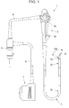
- FIG. 1 is a view of the configuration of the ultrasonic endoscope.
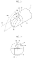
- FIG. 2 is a perspective view of a distal-end part of the ultrasonic endoscope.
- FIG. 3 is a front view of the distal-end part shown in FIG. 2 when seen from the front.
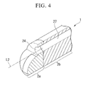
- FIG. 4 is a perspective cross-sectional view of the distal-end part of the ultrasonic endoscope.
- An ultrasonic endoscope 1 includes a slender insertion part 2 for being inserted into a body cavity, an operation part 3 provided at the proximal end of the insertion part 2, and a universal cord 4 that extends from a side part of the operation part 3.
- An endoscope connector 5 is provided at a proximal-end part of the universal cord 4.
- An ultrasonic cable 6 extends from the side part of the endoscope connector 5.
- An ultrasonic connector 7 is provided at a proximal-end part of the ultrasonic cable 6.
- the insertion part 2 includes a distal-end hard part 2a formed from a hard member, a bendable part 2b that can curve, and an elongated flexible tube part 2c that extends from the proximal end of the bendable part 2b to the distal end of the operation part 3, these being connected in that order from the distal-end side.
- An ultrasonic transducer part 10 forms an ultrasonic scan plane 10A for scanning in a forward direction with respect to the insertion axis direction.
- the ultrasonic transducer part 10 has the ultrasonic scan plane 10A that scans in the forward direction.
- a signal cable (not shown) is connected to the ultrasonic transducer part 10. This signal cable extends via the insertion part 2, the operation part 3, the universal cord 4, the endoscope connector 5, and the ultrasonic cable 6, to the ultrasonic connector 7.
- the ultrasonic connector 7 is connected to an ultrasonic observation device (not shown).
- the ultrasonic observation device exchanges signals with the ultrasonic transducer via the signal cable, converts a signal received from the ultrasonic transducer to an ultrasonic image, and displays it on a monitor (not shown).
- the operation part 3 includes an angle knob 3a for executing a bending operation.
- the physician manipulates the angle knob 3a as appropriate, whereby a bendable wire (not shown) is pulled or loosened, and the bendable part 2b curves.
- the ultrasonic transducer part 10 protrudes from a distal-end face 21 of the distal-end hard part 2a of the insertion part 2.
- an observation window 22, an illumination window 23, and an insertion channel exit 24 are provided on the distal-end face 21 of the distal-end hard part 2a.
- the observation window 22 constitutes the most distal-end side of an observation optical system (not shown).
- the illumination window 23 constitutes the most distal-end side of an illumination optical system (not shown).
- the insertion channel exit 24 forms an opening of a treatment tool insertion channel which a treatment tool such as a puncture needle is led through.
- the insertion channel exit 24 is substantially parallel with the longitudinal axis direction of the distal-end hard part 2a, and is connected to a treatment tool insertion channel (hereinafter abbreviated as 'insertion channel') 27 provided in the insertion part 2 (see FIG. 4 ).
- 'insertion channel' treatment tool insertion channel
- the observation optical system and the illumination optical system extend via the insertion part 2, the operation part 3, and the universal cord 4 to the endoscope connector 5.
- the endoscope connector 5 is connected to an endoscope observation device (not shown).
- the endoscope observation device transmits illuminating light through the illumination optical system to the illumination window 23, and the illuminating light illuminates the front of the distal-end hard part 2a.
- the endoscope observation device displays a signal arriving from the observation window 22 via the observation optical system as an observation image on a monitor (not shown). Therefore, the observation image illuminated by the illuminating light is displayed on the monitor.
- the proximal-end side of the insertion channel 27 connects to a treatment tool insertion hole 3d provided in the operation part 3.
- the proximal-end part of the treatment tool insertion hole 3d has a luer-lock shape that allows a syringe to be connected to it.
- a treatment tool inserted through the treatment tool insertion hole 3d is led out from the insertion channel exit 24.
- the center axis L2 of the insertion channel exit 24 is substantially parallel with the longitudinal axis direction of the distal-end hard part 2a.
- the plane defined by the center axis L2 and the perpendicular direction center line L3 of the ultrasonic transducer part 10 is configured to substantially matches the ultrasonic scan plane 10A. Since the treatment tool led out from the insertion channel exit 24 is led out onto the ultrasonic scan plane 10A, it is visibly displayed on the ultrasonic image.
- FIG. 5 is a view of the configuration of an ultrasonic endoscope 1'.
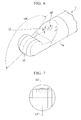
- FIG. 6 is a perspective view of a distal-end part of the ultrasonic endoscope 1'.
- FIG. 7 is a front view of the distal-end part shown in FIG. 5 when seen from the front face.
- FIG. 8 is a perspective cross-sectional view of the distal-end part of the ultrasonic endoscope 1'.
- the ultrasonic endoscope 1' sections having a configuration similar to that of the ultrasonic endoscope 1 described above are designated with the same reference numerals in FIGS. 5 to 8 .
- a point of difference with the ultrasonic endoscope 1 is that the ultrasonic transducer part 10' at the distal end is larger.
- the ultrasonic scan plane 10A' that scans in a forward direction with respect to the insertion axis direction has a wider field of view.
- the insertion channel exit 24' of the ultrasonic endoscope 1' is tilted at an angle ⁇ with respect to the longitudinal axis direction of the distal-end hard part 2a', such that the treatment tool led out from the insertion channel exit does not make contact with the large ultrasonic transducer part 10'.
- the plane defined by the longitudinal direction center axis L2' of the insertion channel exit 24' and the perpendicular direction center line L3' of the ultrasonic transducer 10' is configured to be substantially matched to the ultrasonic scan plane 10A'.
- This configuration is the same as the ultrasonic endoscope 1.
- the treatment tool led out from the insertion channel exit 24' is therefore led out onto the ultrasonic scan plane 10A' and visibly displayed on the ultrasonic image.
- FIG. 9 is an overall exterior view of the puncture needle for ultrasound biopsy.
- FIGS. 10 and 11 are overall cross-sectional views.
- FIGS. 12A, 12B , 13A and 13B are views for explaining the shape of a needle tube.
- FIGS. 14A and 14B are explanatory views of an implant.
- a puncture needle for ultrasound biopsy 30 includes an insertion part 31 and an operation part 32.
- the insertion part 31 is the section that is inserted into the insertion channel 27 of the ultrasonic endoscope 1.
- the operation part 32 is provided at the proximal-end part of the insertion part 31, and is secured to the treatment tool insertion hole 3d of the ultrasonic endoscope 1.
- a sheath 33 is a flexible tube, and is disposed on the outermost side of the insertion part 31.
- a resin such as, for example, polyetheretherketone, polyethersulfone, or Teflon (Registered Trademark) is suitable as the material for the sheath 33.
- a metal wire conventionally known as a flexible shaft, particularly a wound metal formed by winding a stainless steel wire in the shape of a coil spring, is suitable as the material for the sheath 33.
- a needle tube 34 is inserted into an inner cavity of the sheath 33. The needle tube 34 and the insertion channel 27 are prevented from being damaged by direct contact between the needle tube 34 and the inner face of the insertion channel 27.
- the needle tube 34 is formed from, for example, a slender and thin stainless steel pipe or such like, and has a sharp distal end.
- the needle tube 34 is inserted into the sheath 33 such that it can advance/retract.
- FIGS. 12A to 13B show the region near the distal end of the needle tube 34 in greater detail.
- the needle tube 34 is in a natural state, at least the region near the distal end is curved smoothly in a circular arc. While the most distal end of the needle tube 34 is not curved in a circular arc in FIGS. 12A and 12B , it can be included within the section that is curved in a circular arc.
- the distal end of the needle tube 34 is cut into a diagonal shape like a conventional syringe, and an inner cavity is open in the diagonally cut face.
- the direction perpendicular to the distal-end face i.e. the direction to visualize the largest area of the opening 34a (indicated by arrow A1 in FIG. 12A ), is substantially parallel with the plane 34b that contains the longitudinal center axis of the needle tube 34.
- a point 34d at the most proximal-end side of the opening 34a is coplanar with the plane 34b.
- the distal end of the needle tube 34 is cut in the reverse direction to the example shown in FIGS. 12A and 12B ; either can be selected depending on the objective.
- An implant 35 is a metal piece containing a substance that generates very weak radiation for treatment purposes.
- FIGS. 14A and 14B show the implant 35 in greater detail. Its shape is formed by bending a rod-like material that is more slender than the inner cavity of the needle tube 34, obtaining a rod spring with elasticity.
- the implant 35 filled into the distal end of the inner cavity of the needle tube 34 has elasticity, and thus pushes the inner wall of the needle tube 34 with a force of attempting to return to its former shape. Therefore, it is not easily dislodged from the needle tube 34.
- a stylet 36 is a slender wire.
- the stylet 36 is made from, for example, stainless steel or nickel titanium.
- the stylet 36 is disposed on the proximal-end side of the inner cavity of the needle tube 34 so that it can be inserted and removed. By an operation described below, the stylet 36 pushes the implant 35 out from the needle tube 34.
- An operation-part main unit 37 is formed from a resin member.
- a slider 38 is provided so as to slide with respect to the operation-part main unit 37.
- the slider 38 is formed from a resin member.
- a stopper 39 is a member configured such that a sliding distance of the slider 38 with respect to the operation-part main unit 37 can be set at a desired value in accordance with a result of measuring the sliding distance, and is configured as follows.
- a stopper member 39a is disposed so as to slide with respect to the operation-part main unit 37.
- the stopper member 39a is made from, for example, a resin.
- a fixing screw (a stopper screw) 39b is screwed into the stopper member 39a, and fix the stopper member 39a in a desired position.
- the fixing screw 39b is made from metal or a hard resin.
- the operation-part main unit 37 is shaped like a slender pipe, with a flange part 37a at its proximal-end part.
- a resin connection part 40 fixed to the proximal-end part of the sheath 33 is adhesively fixed to a distal-end part of the operation-part main unit 37.
- On the distal-end side of the connection part 40 a screw 40a, which is fixed and connected to the treatment tool insertion hole 3d of the ultrasonic endoscope 1, is formed.
- the proximal-end part of the connection part 40 includes a recess 40b in which the distal-end part of the operation-part main unit 37 is disposed.
- the sheath 33 is fixed to a distal-end connection part 40c formed in the connection part 40.
- a recess is formed in the inner peripheral face of the flange part 37a.
- An O-ring 41 which holds a guide pipe described below is disposed in the recess in the flange part 37a.
- a notched step 37b which has a flat-faced part that the fixing screw 39b contacts is formed at a predetermined position on the outer peripheral face further to the distal-end side than the flange part 37a.
- the distal-end face of the fixing screw 39b is in contact with the flat-faced part of the notched step 37b at a predetermined torque, whereby the slider 38 is arranged on the proximal-end side of the operation-part main unit 37.
- the distal-end parts of the needle tube 34 and the stylet 36 are arranged inside the sheath 33. Even if the slider 38 is moved to the distal-end side due to some kind of external force, the side part of the fixing screw 39b contacts the rising part of the notched step 37b and stops the slider 38 from moving toward the distal-end side. In this contacting state, the distal-end parts of the needle tube 34 and the stylet 36 do not, of course, protrude from the distal end of the sheath 33.
- the stopper member 39a can slide on the operation-part main unit 37 in the longitudinal direction.
- the maximum movable distance of the slider can be set by sliding the stopper member 39a to a given position, and fixing it by screwing in the fixing screw 39b.
- the slider 38 is shaped like a pipe with a small-diameter part 38a at its proximal-end part.
- a sliding arrangement member 42 to arrange the slider 38 so as to slide with respect to the operation-part main unit 37 is adhesively fixed to the distal-end part of the slider 38.
- a resin ferrule member 43 is disposed in the proximal-end opening part of the slider 38.
- the proximal-end part of the needle tube 34, and the proximal-end part of a guide pipe 44 having a distal-end part held by the O-ring 41, are fixed to the distal-end part of the ferrule member 43.
- the proximal-end part of the ferrule member 43 has a luer-lock shape that allows a syringe or the like to be connected to it.
- the stylet 36 is inserted from the ferrule member of the slider 38.
- a resin knob 36a is provided in a single piece at the proximal-end part of the stylet 36.
- the puncture needle for ultrasound biopsy 30 having the above configuration is stored in a sterilization bag (not shown) and disinfected after the constitutive members are assembled.
- the physician takes the puncture needle for ultrasound biopsy 30 stored in a sterilization bag (not shown) out of the sterilization bag.
- the physician then inserts the sheath 33 from the treatment tool insertion hole 3d of the ultrasonic endoscope 1 into the insertion channel 27, screws the screw 40a provided at the connection part 40 of the operation part 32 into the treatment tool insertion hole 3d, and thus fixes the puncture needle for ultrasound biopsy 30 to the ultrasonic endoscope 1.
- an ultrasonic image of the distal-end part of the sheath 33 is clearly depicted on an ultrasonic observation image showing the target region.
- the physician sets the positional relationship between the distal end of the sheath 33 and the target region. Then, the physician measures the distance between them.
- the physician loosens the fixing screw 39b, and slides the stopper member 39a on the operation-part main unit 37 in correspondence with the above-mentioned distance.
- the physician tightens the fixing screw 39b.
- the physician grips the slider 38, and moves it rapidly toward the stopper 39.
- the tip of the needle tube 34 thus reliably pierces the target region.
- the physician pushes the knob 36a of the stylet 36 to the distal-end side.
- the stylet 36 is moved to the distal-end side, and the implant 35 is delivered from the opening 34a at the distal end of the needle tube 34, and is deposited inside the body.
- the physician To deposit the implant 35 accurately in the target region, the physician must check the implant 35 on the ultrasonic observation image while the physician delivers it. Accordingly, in the embodiment of the present invention, the angular position of the needle tube 34 around the axis is controlled so as to match the direction of delivering the implant 35 with the ultrasonic scan plane. A method of matching the direction of delivering the implant 35 with the ultrasonic scan plane is explained below.
- the ultrasonic transducer part 10 disposed at the distal end of the ultrasonic endoscope 1 must be brought firmly into contact with the body tissue.
- the bendable part 2b of the insertion part 2 since the ultrasonic endoscope 1 is inserted into the body-cavity tissue 50, to bring the ultrasonic transducer 10 firmly into contact with the tissue, the bendable part 2b of the insertion part 2 must be curved in the direction normally termed 'up' and directed toward the body-cavity tissue 50.
- the bendable part 2b is shaped substantially like a circular arc, and, naturally, so is the insertion channel 27 disposed inside it.
- the plane 51 containing the longitudinal center axis of the insertion channel 27 is now substantially coplanar with the ultrasonic scan plane 10A.
- FIGS. 16A to 16C illustrate the state of the insertion part 31 of the puncture needle for ultrasound biopsy 30, including the needle tube 34 with the section near its distal end curved smoothly in a circular-arc shape, being passed through the curved insertion channel 27 in chronological sequence of the operation.
- the distal end of the insertion part 31 has been pushed to just before the curved part of the insertion channel 27 of the ultrasonic endoscope 1.
- the circular-arc shape of the needle tube 34 reaches the curved shape of the insertion part 2.
- the needle tube 34 receives a force from the inner wall of the insertion channel 27, and the needle tube 34 is consequently made to rotate around the longitudinal axis, such that the circular-arc shape of the insertion channel 27 and the circular-arc shape of the needle tube 34 are coplanar (including substantially coplanar).
- the plane 34b containing the longitudinal center axis of the needle tube 34 i.e. the plane containing an axis that matches the direction of the opening in the needle tube 34
- the plane 34b becomes substantially coplanar with the ultrasonic scan plane 10A.
- FIG. 16C illustrates the state when the insertion part 31 has reached the predetermined position. While the angular position of the needle tube 34 around the axis is unchanged from that in FIG. 16B , the length of the overlap between the circular-arc shape of the needle tube 34 and the curved shape of the insertion part 2 increases, and the angular position of the needle tube 34 around the axis is therefore more stable. Since the direction A1 for visualizing the largest area of the opening 34a is substantially parallel with the plane 34b, the direction A1 becomes substantially parallel with the ultrasonic scan plane 10A. In other words, the axis matching the direction of the opening in the needle tube 34 becomes substantially parallel with the ultrasonic scan plane 10A.
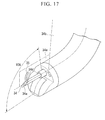
- the implant 35 has elasticity, and is an extended state while being stored inside the needle tube 34. As shown in FIG. 17 , when the implant 35 is delivered from the opening 34a of the needle tube 34, it attempts to return from the extended state to its original shape. The implant 35 consequently rubs against the point 34d at the most proximal-end side of the opening 34a as it is delivered. The implant 35 is now delivered within a plane 34e.
- the plane 34e is substantially the same as the plane 34b and contains the proximal-end point 34d.
- the implant 35 can be favorably confirmed on the ultrasonic image.
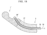
- FIG. 18 is a state where the insertion part 31 of the puncture needle for ultrasound biopsy 30, including the needle tube 34 with a part near the distal-end that is curved in a circular-arc shape in a natural state, has been passed along the curved insertion channel 27, and has reached a predetermined position.
- the insertion channel exit 24' tilts at an angle ⁇ with respect to the longitudinal axis direction of the distal-end hard part 2a', such that the treatment tool led out from the insertion channel exit 24' does not make contact with the large ultrasonic transducer part 10'.
- the bendable part 2b of the endoscope insertion part 2 is curved in the direction normally termed 'up'. It is clear that, in this state, the needle tube 34 curved in a circular-arc shape can be smoothly passed through the cavity formed by the insertion channel exit 24' and the insertion channel 27. Therefore, when the implant 35 is delivered from the opening 34a of the needle tube 34, it can be favorably confirmed on the ultrasonic image.
- FIG. 19 is an overall schematic view of the puncture needle for ultrasound biopsy.
- FIG. 20 is an overall cross-sectional view of the puncture needle for ultrasound biopsy.
- An injection syringe 52 is attached to a resin ferrule member 43.
- the injection syringe 52 includes a cylinder ferrule 52a, a cylinder 52b, and a piston 52c, and the cylinder 52b is filled with a gaseous or liquid medicine 53.
- the mechanism for controlling the angular position of the needle tube 34 around the axis is similar to that of the first embodiment, and is not repetitiously explained.
- the medicine 53 passes along the inner cavity of the needle tube 34 and is released into the body from the opening 34a, whereby the medicine 53 is released onto the ultrasonic scan plane 10A. Therefore, it is possible to favorably confirm on the ultrasonic image that the medicine 53 is being delivered.
- the substance being delivered into the body can be a solid such as the implant 35, or it can be a gas or liquid such as the medicine 53.
- the puncture needle for ultrasound biopsy according to the present embodiment has the same configuration as the first embodiment when delivering a solid.
- the puncture needle for ultrasound biopsy according to the present embodiment has the same configuration as the second embodiment when delivering a gas or liquid such as the medicine 53. Therefore, only points of difference in the configuration from the first and the second embodiments are described.
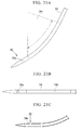
- the distal end of the needle tube 54 is sharp, and an opening 54a is provided in its side face.
- the direction to visualize this opening 54a from the front i.e. the direction to visualize the largest area (indicated by arrow A2 in FIGS. 21A and 21C ) is substantially parallel with the plane 54b that contains the longitudinal center axis of the needle tube 54.
- the opening 54a is one in this example, openings can be appropriately provided in accordance with the desired dispersal range of the medicine.
- another opening can be provided at a position 180-degree opposite to the opening 54a.
- a plurality of openings can be provided along the longitudinal direction of the needle tube 54.
- ultrasonic reflection machining is sometimes used to enhance the visibility of the needle tube on the ultrasonic image.
- a great many minute recesses such as dimples are formed on the surface of the needle tube, or the surface is made rougher.
- the needle tube 54 is configured such that a pattern of ultrasonic reflected from near the opening 54a is different from that of ultrasonic reflected from the distal-end side and proximal-end side of the opening 54a. Specific examples of such ultrasonic reflection are shown in FIGS. 22A and 22B .
- ultrasonic reflection machining 57 is performed around an opening 55a in a needle tube 55.
- Ultrasonic reflection machining 56 with a different ultrasonic reflectivity to the ultrasonic reflection machining 57 is performed at the front and rear of the opening 55a in the longitudinal direction.
- machining is not performed to the surface around an opening 58a in a needle tube 58, and ultrasonic reflection machining 56 is performed at the front and rear of the opening 58a in the longitudinal direction, so that the ultrasonic reflection pattern is different.
- the mechanism for controlling the angular position of the needle tube around the axis is similar to that of the first embodiment, and is not repetitiously explained.
- the substance being delivered into the body can be a solid such as the implant 35, or it can be a gas or liquid such as the medicine 53.
- the puncture needle for ultrasound biopsy according to the present embodiment has the same configuration as the first embodiment when delivering a solid.
- the puncture needle for ultrasound biopsy according to the present embodiment has the same configuration as the second embodiment when delivering a gas or liquid such as the medicine 53. Therefore, only points of difference in the configuration from the first to the third embodiments are described.
- a needle tube 60 shown in FIG. 23 the center of the outer diameter thereof is displaced from the center of the inner cavity thereof, and an opening 60a is formed at the distal end thereof.
- the opening 60a is provided such that the direction to visualize the largest area of the opening 60a (indicated by arrow A3 in FIG. 23 ) is substantially parallel with a longitudinal cross-sectional plane 60f that contains a line 60e connecting the thinnest part 60c and the thickest part 60d of the needle tube.
- the needle tube 60 maintains a linear shape (including a substantially linear shape).
- the needle tube 60 is made to rotate around the longitudinal axis such that the thinnest part of the needle tube 60 is disposed on the inner side of the curve of the ultrasonic endoscope 1.
- the longitudinal cross-sectional plane 60f that contains the line 60e connecting the thinnest and thickest parts of the needle tube 60 becomes substantially the same as the ultrasonic scan plane 10A. Therefore, the direction A3 to visualize the largest area of the opening 60a becomes substantially parallel with the ultrasonic scan plane 10A. The substance that has been delivered can thus be favorably confirmed on the ultrasonic image.
- the configuration of the needle tube differs from that in the first to the fourth embodiments is explained as a fifth embodiment.
- the substance being delivered into the body can be a solid such as the implant 35, or it can be a gas or liquid such as the medicine 53.
- the puncture needle for ultrasound biopsy according to the present embodiment has the same configuration as the first embodiment when delivering a solid.
- the puncture needle for ultrasound biopsy according to the present embodiment has the same configuration as the second embodiment when delivering a gas or liquid such as the medicine 53. Therefore, only points of difference in the configuration from the first to fourth embodiments are described.
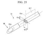
- a needle tube 61 shown in FIG. 25 has a flat cross-sectional shape, such as an ellipse, an oval, or a rectangle, and the direction to visualize the largest area of an opening 61a in the needle tube 61 (indicated by arrow A4 in FIG. 25 ) is substantially parallel with a longitudinal cross-sectional plane 61f that contains the short-diameter center axis 61e of the flat shape of the needle tube.
- the needle tube 61 is made to rotate around the longitudinal axis in a direction such that the short-diameter side faces the center of the curve.
- the longitudinal cross-sectional plane 61f that contains the short-diameter center axis 61e of the needle tube becomes substantially parallel with the ultrasonic scan plane 10A. Therefore, the direction A4 to visualize the largest area of the opening 61 a becomes substantially parallel with the ultrasonic scan plane 10A.
- the substance that has been delivered can be favorably confirmed on the ultrasonic image.
- the configuration of the needle tube differs from that in the first embodiment is explained as a sixth embodiment.
- the substance being delivered into the body is a solid such as the implant 35. Accordingly, other than the configuration of the distal end of the needle tube, the present embodiment has the same configuration as the first embodiment, and therefore only points of difference are described.
- a needle tube 62 shown in FIG. 27 has an inner cavity formed in a flat cross-sectional shape, such as an ellipse, an oval, or a rectangle.
- the direction to visualize the largest area of an opening 62a in the needle tube is substantially parallel with a longitudinal cross-sectional plane 62d that contains the long-diameter direction 62c of the flat shape.
- the implant 35 is stored in the needle tube 62. Since the implant 35 attempts to return to its original shape inside the needle tube 62, it is stored such that it stretches in the long-diameter direction in the inner cavity.
- the needle tube 62 has a certain amount of flexibility, and the force of the implant 35 attempting to return to its original shape is strong enough to make the needle tube 62 curve. Consequently, as shown in FIG. 28 , the section of the needle tube 62 which the implant 35 is stored in (i.e. the region near the distal end of the needle tube 62) curves in a smooth circular-arc shape in the longitudinal cross-sectional plane 62d. As a result, while the size of the circular-arc shape region of the needle tube 62 depends on the size of the implant 35, in external appearance it has a shape broadly similar to that of the needle tube 34 shown in FIG. 12 .
- the implant 35 can be favorably confirmed on the ultrasonic image.
- the puncture needle for ultrasound biopsy capable of accurately delivering a substance to a region of interest while favorably observing the delivery of the substance with the ultrasonic endoscope.
- a substance can be accurately delivered to a region of interest while the delivery of the substance is favorably being observed with the ultrasonic endoscope by matching the angular direction position of the needle tube opening part to the ultrasonic scan plane of the ultrasonic endoscope.
Landscapes
- Health & Medical Sciences (AREA)
- Life Sciences & Earth Sciences (AREA)
- Surgery (AREA)
- Medical Informatics (AREA)
- Animal Behavior & Ethology (AREA)
- Engineering & Computer Science (AREA)
- Biomedical Technology (AREA)
- Heart & Thoracic Surgery (AREA)
- Pathology (AREA)
- Molecular Biology (AREA)
- Nuclear Medicine, Radiotherapy & Molecular Imaging (AREA)
- General Health & Medical Sciences (AREA)
- Public Health (AREA)
- Veterinary Medicine (AREA)
- Physics & Mathematics (AREA)
- Biophysics (AREA)
- Radiology & Medical Imaging (AREA)
- Ultra Sonic Daignosis Equipment (AREA)
- Surgical Instruments (AREA)
Abstract
Description
- The present invention relates to a puncture needle for ultrasound biopsy that is inserted into a body cavity and used for delivering medicine and treatment devices into the body.
Priority is claimed onUS Provisional Patent Application No. 61/490,676 - Hitherto, to inspect and diagnose an affected part in a body cavity, a procedure of sucking and removing body tissue and body fluid has been performed. This procedure is performed by using a puncture needle to pierce the stomach, the duodenal wall, or the like, and puncture a target region of an underlying organ such as the pancreas, the liver, or the kidney while observing the inside of a body cavity through an ultrasonic endoscope. This is termed Endoscopic Ultrasound-guided Fine-Needle Aspiration (EUS-FNA).
- Instead of sucking out tissue or body fluid, the EUS-FNA procedure is recently being applied in research into treatment procedures for delivering medicine, a marker, or a substance such as a radioactive source from a puncture needle directly to the region of interest. In such treatment procedures, by delivering the substance accurately to the region of interest, we can expect the effect of the treatment to be enhanced and side-effects to be reduced. It is therefore preferable to perform the procedure while using an ultrasonic endoscope to observe the substance as it is actually being delivered.
- However, the substance to be delivered from a needle tube may not be able to be confirmed on an ultrasonic image in a case where the above treatment in which the puncture needle for EUS-FNA is directly applied is performed. A direction in which the substance is delivered from the needle tube has to be matched to an ultrasonic scan plane in order to confirm the delivery of the substance from the needle tube on the ultrasonic image. For this reason, since an opening part for releasing the substance provided on the needle tube needs to be disposed on the ultrasonic scan plane in a state where the puncture needle is inserted into an insertion channel of the ultrasonic endoscope, it is necessary to regulate an angular position of the needle tube around an axis. However, the ultrasonic endoscope has a long flexible insertion part, and the insertion part is complicatedly curved when the insertion part reaches the target region in the body. Therefore, it is difficult to adjust the angular position of the needle tube, which passes through the insertion part, around the axis by an operation of an operation part at hand. It is also difficult to arrange the opening part for releasing the substance provided on the needle tube on the ultrasonic scan plane at all times. As a result, it may be difficult to accurately deliver the substance to the region of interest since the delivery of the substance cannot be observed with the ultrasonic endoscope.
- Because of the above-described problems, a puncture needle for ultrasound biopsy capable of matching an angular position of a needle tube opening part around an axis to an ultrasonic scan plane of an ultrasonic endoscope has been anticipated.
- The objective of the present invention is to provide a puncture needle for ultrasound biopsy capable of accurately delivering a substance to a region of interest while the delivery of the substance is favorably being observed with an ultrasonic endoscope.
- The following means are proposed in the present invention in order to solve the above-described problems.
According to a first aspect of the present invention, a puncture needle for ultrasound biopsy includes a sheath, an operation part, a needle tube, and a releasing mechanism, and is used in combination with an ultrasonic endoscope. The sheath is inserted into an insertion channel of the ultrasonic endoscope so as to be capable of advancing and retracting. The operation part is provided at a proximal-end part of the sheath, and doubles as a gripping part which a user grips. The needle tube is inserted into the sheath, includes an opening formed in a distal-end region thereof, and is configured to puncture a tissue in a body cavity. The releasing mechanism is fitted to a proximal-end side of the needle tube, and releases a substance filled therein from the opening of the needle tube to an outside. Moreover, the needle tube is rotated around a longitudinal axis of the insertion channel by receiving a force from an inner wall of the insertion channel such that an axis line matching a direction of the opening in the needle tube protruding from the insertion channel becomes substantially parallel with an ultrasonic scanning face of the ultrasonic endoscope. - According to a second aspect of the present invention, in a natural state, at least a region near a distal end of the needle tube is curved smoothly in a circular arc, and a direction to visualize a largest area of the opening of the needle tube is substantially parallel with a plane formed by a circular-arc shape of the needle tube.
- According to a third aspect of the present invention, a center of an outer diameter of the needle tube is displaced from a center of an inner cavity of the needle tube, and a direction to visualize a largest area of the opening of the needle tube is substantially parallel with a cross-sectional plane connecting a thinnest part and a thickest part of the needle tube.
- According to a fourth aspect of the present invention, an outer-diameter cross-sectional face of the needle tube has a flat shape, and a direction to visualize a largest area of the opening of the needle tube is substantially parallel with a short-diameter cross-sectional plane of the flat shape of the needle tube.
- According to a fifth aspect of the present invention, in a natural state, at least a region near a distal end of the needle tube is curved smoothly in a circular arc, and a most proximal-end side of the opening of the needle tube is in a plane formed by a circular-arc shape of the needle tube.
- According to a sixth aspect of the present invention, a center of an outer diameter of the needle tube is displaced from a center of an inner cavity of the needle tube, and a most proximal-end side of the opening of the needle tube is in a cross-sectional plane connecting a thinnest part and a thickest part of the needle tube.
- According to a seventh aspect of the present invention, an outer-diameter cross-sectional face of the needle tube has a flat shape, and a most proximal-end side of the opening of the needle tube is in a short-diameter cross-sectional plane of the flat shape.
- According to an eighth aspect of the present invention, an inner cavity cross-sectional plane of the needle tube has a flat shape, and a direction to visualize a largest area of the opening is parallel with a longitudinal direction of the flat shape.
- According to a ninth aspect of the present invention, an ultrasonic reflection machining for obtaining a reflected echo is performed on a distal-end part surface of the needle tube, a pattern of the ultrasonic reflection machining around the opening being different from that in other regions.
- Preferably, the distal-end region covers a distal end.
- Preferably, the distal-end region covers a region near a distal end.
- Preferably, the substance includes gas.
- Preferably, the substance includes liquid.
- Preferably, the substance includes a solid.
- Preferably, the solid includes a slender elastic body.
- According to the puncture needle for ultrasound biopsy, a substance can be accurately delivered to a region of interest while the delivery of the substance is favorably being observed with the ultrasonic endoscope by matching the angular direction position of the needle tube opening part to the ultrasonic scan plane of the ultrasonic endoscope.
-
-
FIG. 1 is an overall view of an ultrasonic endoscope used in combination with a puncture needle for ultrasound biopsy according to a first embodiment of the present invention. -
FIG. 2 is a perspective view of a distal-end part of the ultrasonic endoscope. -
FIG. 3 is a front view of the distal-end part of the ultrasonic endoscope. -
FIG. 4 is a perspective cross-sectional view of the distal-end part of the ultrasonic endoscope. -
FIG. 5 is an overall view of another ultrasonic endoscope used in combination with the puncture needle for ultrasound biopsy according to the first embodiment. -
FIG. 6 is a perspective view of a distal-end part of the another ultrasonic endoscope according to the first embodiment. -
FIG. 7 is a front view of a distal-end part of the another ultrasonic endoscope. -
FIG. 8 is a perspective cross-sectional view of the distal-end part of the another ultrasonic endoscope. -
FIG. 9 is an overall exterior view of the puncture needle for ultrasound biopsy according to the first embodiment. -
FIG. 10 is an overall cross-sectional view of the puncture needle for ultrasound biopsy according to the first embodiment. -
FIG. 11 is an overall cross-sectional view of the puncture needle for ultrasound biopsy according to the first embodiment. -
FIG. 12A is a view of a distal-end side of a needle tube of the puncture needle for ultrasound biopsy according to the first embodiment. -
FIG. 12B is a view of the distal-end side of the needle tube of the puncture needle for ultrasound biopsy according to the first embodiment. -
FIG. 13A is a view of a distal-end side of another example of the needle tube according to the first embodiment. -
FIG. 13B is a view of the distal-end side of the another example of the needle tube according to the first embodiment. -
FIG. 14A is a view of an implant stored in the needle tube according to the first embodiment and a sixth embodiment. -
FIG. 14B is a view of a state where the implant to be stored in the needle tube according to the first embodiment has been stored in the needle tube according to the first embodiment. -
FIG. 15 is a view of an operation of the ultrasonic endoscope when the puncture needle for ultrasound biopsy according to the first embodiment is being used. -
FIG. 16A is a view of an operation of the puncture needle for ultrasound biopsy according to the first embodiment in a curved ultrasonic endoscope. -
FIG. 16B is a view of the operation of the puncture needle for ultrasound biopsy according to the first embodiment in the curved ultrasonic endoscope. -
FIG. 16C is a view of the operation of the puncture needle for ultrasound biopsy according to the first embodiment in the curved ultrasonic endoscope. -
FIG. 17 is a view of a state where the implant has been delivered from the puncture needle for ultrasound biopsy according to the first embodiment. -
FIG. 18 is a view of a state where the puncture needle for ultrasound biopsy according to the first embodiment has been inserted into the another ultrasonic endoscope. -
FIG. 19 is an overall schematic view of a puncture needle for ultrasound biopsy according to a second embodiment of the present invention. -
FIG. 20 is an overall cross-sectional view of the puncture needle for ultrasound biopsy according to the second embodiment. -
FIG. 21A is a view of a distal-end side of a needle tube of a puncture needle for ultrasound biopsy according to a third embodiment of the present invention. -
FIG. 21B is a view of the distal-end side of the needle tube of the puncture needle for ultrasound biopsy according to the third embodiment of the present invention. -
FIG. 21C is a view of the distal-end side of the needle tube of the puncture needle for ultrasound biopsy according to the third embodiment of the present invention. -
FIG. 22A is an example of an ultrasonic reflection machining performed to the needle tube according to the third embodiment. -
FIG. 22B is an example of the ultrasonic reflection machining performed to the needle tube according to the third embodiment. -
FIG. 23 is a view of a distal-end side of a needle tube of a puncture needle for ultrasound biopsy according to a fourth embodiment of the present invention. -
FIG. 24A is a view of an operation of the puncture needle for ultrasound biopsy according to the fourth embodiment in a curved ultrasonic endoscope. -
FIG. 24B is a view of the operation of the puncture needle for ultrasound biopsy according to the fourth embodiment in the curved ultrasonic endoscope. -
FIG. 25 is a view of a distal-end side of a needle tube of a puncture needle for ultrasound biopsy according to a fifth embodiment of the present invention. -
FIG. 26A is a view of an operation of the puncture needle for ultrasound biopsy according to the fifth embodiment in a curved ultrasonic endoscope. -
FIG. 26B is a view of the operation of the puncture needle for ultrasound biopsy according to the fifth embodiment in the curved ultrasonic endoscope. -
FIG. 27 is a view of a distal-end side of a needle tube of a puncture needle for ultrasound biopsy according to the sixth embodiment of the present invention. -
FIG. 28 is a view of a state where an implant has been stored in the needle tube according to the sixth embodiment. - Embodiments of the present invention are explained with reference to the drawings.
- A puncture needle for ultrasound biopsy according to the present embodiment is used in combination with an ultrasonic endoscope.
An ultrasonic endoscope according to the present embodiment is explained usingFIGS. 1 to 4 .FIG. 1 is a view of the configuration of the ultrasonic endoscope.FIG. 2 is a perspective view of a distal-end part of the ultrasonic endoscope.FIG. 3 is a front view of the distal-end part shown inFIG. 2 when seen from the front.FIG. 4 is a perspective cross-sectional view of the distal-end part of the ultrasonic endoscope. - An
ultrasonic endoscope 1 includes aslender insertion part 2 for being inserted into a body cavity, anoperation part 3 provided at the proximal end of theinsertion part 2, and auniversal cord 4 that extends from a side part of theoperation part 3. - An
endoscope connector 5 is provided at a proximal-end part of theuniversal cord 4. Anultrasonic cable 6 extends from the side part of theendoscope connector 5. Anultrasonic connector 7 is provided at a proximal-end part of theultrasonic cable 6. - The
insertion part 2 includes a distal-endhard part 2a formed from a hard member, abendable part 2b that can curve, and an elongatedflexible tube part 2c that extends from the proximal end of thebendable part 2b to the distal end of theoperation part 3, these being connected in that order from the distal-end side. - An
ultrasonic transducer part 10 forms anultrasonic scan plane 10A for scanning in a forward direction with respect to the insertion axis direction. In other words, theultrasonic transducer part 10 has theultrasonic scan plane 10A that scans in the forward direction. A signal cable (not shown) is connected to theultrasonic transducer part 10. This signal cable extends via theinsertion part 2, theoperation part 3, theuniversal cord 4, theendoscope connector 5, and theultrasonic cable 6, to theultrasonic connector 7. - The
ultrasonic connector 7 is connected to an ultrasonic observation device (not shown). The ultrasonic observation device exchanges signals with the ultrasonic transducer via the signal cable, converts a signal received from the ultrasonic transducer to an ultrasonic image, and displays it on a monitor (not shown). - The
operation part 3 includes anangle knob 3a for executing a bending operation. The physician manipulates theangle knob 3a as appropriate, whereby a bendable wire (not shown) is pulled or loosened, and thebendable part 2b curves. - As shown in
FIG. 2 , theultrasonic transducer part 10 protrudes from a distal-end face 21 of the distal-endhard part 2a of theinsertion part 2. Moreover, anobservation window 22, anillumination window 23, and aninsertion channel exit 24 are provided on the distal-end face 21 of the distal-endhard part 2a. Theobservation window 22 constitutes the most distal-end side of an observation optical system (not shown). Theillumination window 23 constitutes the most distal-end side of an illumination optical system (not shown). Theinsertion channel exit 24 forms an opening of a treatment tool insertion channel which a treatment tool such as a puncture needle is led through. Theinsertion channel exit 24 is substantially parallel with the longitudinal axis direction of the distal-endhard part 2a, and is connected to a treatment tool insertion channel (hereinafter abbreviated as 'insertion channel') 27 provided in the insertion part 2 (seeFIG. 4 ). - The observation optical system and the illumination optical system (both not shown) extend via the
insertion part 2, theoperation part 3, and theuniversal cord 4 to theendoscope connector 5. Theendoscope connector 5 is connected to an endoscope observation device (not shown). The endoscope observation device transmits illuminating light through the illumination optical system to theillumination window 23, and the illuminating light illuminates the front of the distal-endhard part 2a. The endoscope observation device displays a signal arriving from theobservation window 22 via the observation optical system as an observation image on a monitor (not shown). Therefore, the observation image illuminated by the illuminating light is displayed on the monitor. - The proximal-end side of the
insertion channel 27 connects to a treatmenttool insertion hole 3d provided in theoperation part 3. The proximal-end part of the treatmenttool insertion hole 3d has a luer-lock shape that allows a syringe to be connected to it. A treatment tool inserted through the treatmenttool insertion hole 3d is led out from theinsertion channel exit 24. - The center axis L2 of the
insertion channel exit 24 is substantially parallel with the longitudinal axis direction of the distal-endhard part 2a. The plane defined by the center axis L2 and the perpendicular direction center line L3 of theultrasonic transducer part 10 is configured to substantially matches theultrasonic scan plane 10A. Since the treatment tool led out from theinsertion channel exit 24 is led out onto theultrasonic scan plane 10A, it is visibly displayed on the ultrasonic image. - Another ultrasonic endoscope that can be used in the present embodiment is explained using
FIGS. 5 to 8 .FIG. 5 is a view of the configuration of an ultrasonic endoscope 1'.FIG. 6 is a perspective view of a distal-end part of the ultrasonic endoscope 1'.FIG. 7 is a front view of the distal-end part shown inFIG. 5 when seen from the front face.FIG. 8 is a perspective cross-sectional view of the distal-end part of the ultrasonic endoscope 1'. - In the ultrasonic endoscope 1', sections having a configuration similar to that of the
ultrasonic endoscope 1 described above are designated with the same reference numerals inFIGS. 5 to 8 . A point of difference with theultrasonic endoscope 1 is that the ultrasonic transducer part 10' at the distal end is larger. As a result, theultrasonic scan plane 10A' that scans in a forward direction with respect to the insertion axis direction has a wider field of view. - Moreover, as shown in
FIG. 6 , the insertion channel exit 24' of the ultrasonic endoscope 1' is tilted at an angle α with respect to the longitudinal axis direction of the distal-endhard part 2a', such that the treatment tool led out from the insertion channel exit does not make contact with the large ultrasonic transducer part 10'. - However, the plane defined by the longitudinal direction center axis L2' of the insertion channel exit 24' and the perpendicular direction center line L3' of the ultrasonic transducer 10' is configured to be substantially matched to the
ultrasonic scan plane 10A'. This configuration is the same as theultrasonic endoscope 1. The treatment tool led out from the insertion channel exit 24' is therefore led out onto theultrasonic scan plane 10A' and visibly displayed on the ultrasonic image. - Next, a puncture needle for ultrasound biopsy according to the present embodiment is explained using
FIGS. 9 to 14B .FIG. 9 is an overall exterior view of the puncture needle for ultrasound biopsy.FIGS. 10 and11 are overall cross-sectional views.FIGS. 12A, 12B ,13A and 13B are views for explaining the shape of a needle tube.FIGS. 14A and 14B are explanatory views of an implant. - A puncture needle for
ultrasound biopsy 30 according to the present embodiment includes aninsertion part 31 and anoperation part 32. Theinsertion part 31 is the section that is inserted into theinsertion channel 27 of theultrasonic endoscope 1. Theoperation part 32 is provided at the proximal-end part of theinsertion part 31, and is secured to the treatmenttool insertion hole 3d of theultrasonic endoscope 1. - Each part of the
insertion part 31 is explained.
Asheath 33 is a flexible tube, and is disposed on the outermost side of theinsertion part 31. A resin such as, for example, polyetheretherketone, polyethersulfone, or Teflon (Registered Trademark) is suitable as the material for thesheath 33. Alternatively, a metal wire conventionally known as a flexible shaft, particularly a wound metal formed by winding a stainless steel wire in the shape of a coil spring, is suitable as the material for thesheath 33. Aneedle tube 34 is inserted into an inner cavity of thesheath 33. Theneedle tube 34 and theinsertion channel 27 are prevented from being damaged by direct contact between theneedle tube 34 and the inner face of theinsertion channel 27. - The
needle tube 34 is formed from, for example, a slender and thin stainless steel pipe or such like, and has a sharp distal end. Theneedle tube 34 is inserted into thesheath 33 such that it can advance/retract. -
FIGS. 12A to 13B show the region near the distal end of theneedle tube 34 in greater detail. When theneedle tube 34 is in a natural state, at least the region near the distal end is curved smoothly in a circular arc. While the most distal end of theneedle tube 34 is not curved in a circular arc inFIGS. 12A and 12B , it can be included within the section that is curved in a circular arc. - The distal end of the
needle tube 34 is cut into a diagonal shape like a conventional syringe, and an inner cavity is open in the diagonally cut face. The direction perpendicular to the distal-end face, i.e. the direction to visualize the largest area of theopening 34a (indicated by arrow A1 inFIG. 12A ), is substantially parallel with theplane 34b that contains the longitudinal center axis of theneedle tube 34. Apoint 34d at the most proximal-end side of theopening 34a is coplanar with theplane 34b. - In the example shown in
FIGS. 13A and 13B , the distal end of theneedle tube 34 is cut in the reverse direction to the example shown inFIGS. 12A and 12B ; either can be selected depending on the objective. - An
implant 35 is a metal piece containing a substance that generates very weak radiation for treatment purposes.FIGS. 14A and 14B show theimplant 35 in greater detail. Its shape is formed by bending a rod-like material that is more slender than the inner cavity of theneedle tube 34, obtaining a rod spring with elasticity. Theimplant 35 filled into the distal end of the inner cavity of theneedle tube 34 has elasticity, and thus pushes the inner wall of theneedle tube 34 with a force of attempting to return to its former shape. Therefore, it is not easily dislodged from theneedle tube 34. - A
stylet 36 is a slender wire. Thestylet 36 is made from, for example, stainless steel or nickel titanium. Thestylet 36 is disposed on the proximal-end side of the inner cavity of theneedle tube 34 so that it can be inserted and removed. By an operation described below, thestylet 36 pushes theimplant 35 out from theneedle tube 34. - Constitutive elements of the
operation part 32 are explained.
An operation-partmain unit 37 is formed from a resin member.
Aslider 38 is provided so as to slide with respect to the operation-partmain unit 37. Theslider 38 is formed from a resin member. - A
stopper 39 is a member configured such that a sliding distance of theslider 38 with respect to the operation-partmain unit 37 can be set at a desired value in accordance with a result of measuring the sliding distance, and is configured as follows. Astopper member 39a is disposed so as to slide with respect to the operation-partmain unit 37. Thestopper member 39a is made from, for example, a resin. A fixing screw (a stopper screw) 39b is screwed into thestopper member 39a, and fix thestopper member 39a in a desired position. The fixingscrew 39b is made from metal or a hard resin. - The operation-part
main unit 37 is shaped like a slender pipe, with aflange part 37a at its proximal-end part. Aresin connection part 40 fixed to the proximal-end part of thesheath 33 is adhesively fixed to a distal-end part of the operation-partmain unit 37. On the distal-end side of theconnection part 40, ascrew 40a, which is fixed and connected to the treatmenttool insertion hole 3d of theultrasonic endoscope 1, is formed. The proximal-end part of theconnection part 40 includes arecess 40b in which the distal-end part of the operation-partmain unit 37 is disposed. Thesheath 33 is fixed to a distal-end connection part 40c formed in theconnection part 40. - A recess is formed in the inner peripheral face of the
flange part 37a. An O-ring 41 which holds a guide pipe described below is disposed in the recess in theflange part 37a. A notchedstep 37b which has a flat-faced part that the fixingscrew 39b contacts is formed at a predetermined position on the outer peripheral face further to the distal-end side than theflange part 37a.
At the time of manufacture and shipment of the puncture needle forultrasound biopsy 30, the distal-end face of the fixingscrew 39b is in contact with the flat-faced part of the notchedstep 37b at a predetermined torque, whereby theslider 38 is arranged on the proximal-end side of the operation-partmain unit 37. - In this arrangement state, the distal-end parts of the
needle tube 34 and thestylet 36 are arranged inside thesheath 33. Even if theslider 38 is moved to the distal-end side due to some kind of external force, the side part of the fixingscrew 39b contacts the rising part of the notchedstep 37b and stops theslider 38 from moving toward the distal-end side. In this contacting state, the distal-end parts of theneedle tube 34 and thestylet 36 do not, of course, protrude from the distal end of thesheath 33. - When the fixing
screw 39b is loosened, thestopper member 39a can slide on the operation-partmain unit 37 in the longitudinal direction. The maximum movable distance of the slider can be set by sliding thestopper member 39a to a given position, and fixing it by screwing in the fixingscrew 39b. - The
slider 38 is shaped like a pipe with a small-diameter part 38a at its proximal-end part. A slidingarrangement member 42 to arrange theslider 38 so as to slide with respect to the operation-partmain unit 37 is adhesively fixed to the distal-end part of theslider 38. - On the other hand, a
resin ferrule member 43 is disposed in the proximal-end opening part of theslider 38. The proximal-end part of theneedle tube 34, and the proximal-end part of aguide pipe 44 having a distal-end part held by the O-ring 41, are fixed to the distal-end part of theferrule member 43. The proximal-end part of theferrule member 43 has a luer-lock shape that allows a syringe or the like to be connected to it. - The
stylet 36 is inserted from the ferrule member of theslider 38. Aresin knob 36a is provided in a single piece at the proximal-end part of thestylet 36. - The puncture needle for
ultrasound biopsy 30 having the above configuration is stored in a sterilization bag (not shown) and disinfected after the constitutive members are assembled. - An operation of the disposable type of the puncture needle for
ultrasound biopsy 30 having the configuration described above is explained. First, a case where theultrasonic endoscope 1 shown inFIGS. 1 to 4 is combined with theneedle tube 34 shown inFIGS. 12A and 12B is explained. Next, a case that functions in exactly the same way by using the ultrasonic endoscope 1' shown inFIGS. 5 to 8 and theneedle tube 34 shown inFIGS. 13A and 13B is explained. - Firstly, the physician takes the puncture needle for
ultrasound biopsy 30 stored in a sterilization bag (not shown) out of the sterilization bag. The physician then inserts thesheath 33 from the treatmenttool insertion hole 3d of theultrasonic endoscope 1 into theinsertion channel 27, screws thescrew 40a provided at theconnection part 40 of theoperation part 32 into the treatmenttool insertion hole 3d, and thus fixes the puncture needle forultrasound biopsy 30 to theultrasonic endoscope 1. - As a result, an ultrasonic image of the distal-end part of the
sheath 33 is clearly depicted on an ultrasonic observation image showing the target region. Here, the physician sets the positional relationship between the distal end of thesheath 33 and the target region. Then, the physician measures the distance between them. - Next, the physician loosens the fixing
screw 39b, and slides thestopper member 39a on the operation-partmain unit 37 in correspondence with the above-mentioned distance. When the physician has moved thestopper member 39a to a predetermined position, the physician tightens the fixingscrew 39b. - Thereafter, the physician grips the
slider 38, and moves it rapidly toward thestopper 39. The tip of theneedle tube 34 thus reliably pierces the target region. - After checking that the
needle tube 34 has reached the target region, the physician pushes theknob 36a of thestylet 36 to the distal-end side. Thestylet 36 is moved to the distal-end side, and theimplant 35 is delivered from theopening 34a at the distal end of theneedle tube 34, and is deposited inside the body. - To deposit the
implant 35 accurately in the target region, the physician must check theimplant 35 on the ultrasonic observation image while the physician delivers it. Accordingly, in the embodiment of the present invention, the angular position of theneedle tube 34 around the axis is controlled so as to match the direction of delivering theimplant 35 with the ultrasonic scan plane. A method of matching the direction of delivering theimplant 35 with the ultrasonic scan plane is explained below. - Since ultrasonic waves attenuate severely in air, during ultrasonic observation, the
ultrasonic transducer part 10 disposed at the distal end of theultrasonic endoscope 1 must be brought firmly into contact with the body tissue. InFIG. 15 , since theultrasonic endoscope 1 is inserted into the body-cavity tissue 50, to bring theultrasonic transducer 10 firmly into contact with the tissue, thebendable part 2b of theinsertion part 2 must be curved in the direction normally termed 'up' and directed toward the body-cavity tissue 50. When it has been curved, thebendable part 2b is shaped substantially like a circular arc, and, naturally, so is theinsertion channel 27 disposed inside it. Theplane 51 containing the longitudinal center axis of theinsertion channel 27 is now substantially coplanar with theultrasonic scan plane 10A. -
FIGS. 16A to 16C illustrate the state of theinsertion part 31 of the puncture needle forultrasound biopsy 30, including theneedle tube 34 with the section near its distal end curved smoothly in a circular-arc shape, being passed through thecurved insertion channel 27 in chronological sequence of the operation. InFIG. 16A , the distal end of theinsertion part 31 has been pushed to just before the curved part of theinsertion channel 27 of theultrasonic endoscope 1. When theinsertion part 31 is pushed further, as shown inFIG. 16B , the circular-arc shape of theneedle tube 34 reaches the curved shape of theinsertion part 2. As it is inserted, theneedle tube 34 receives a force from the inner wall of theinsertion channel 27, and theneedle tube 34 is consequently made to rotate around the longitudinal axis, such that the circular-arc shape of theinsertion channel 27 and the circular-arc shape of theneedle tube 34 are coplanar (including substantially coplanar). As a result, theplane 34b containing the longitudinal center axis of the needle tube 34 (i.e. the plane containing an axis that matches the direction of the opening in the needle tube 34) becomes the same as theplane 51 containing the long center axis of theinsertion channel 27. Therefore, theplane 34b becomes substantially coplanar with theultrasonic scan plane 10A. -
FIG. 16C illustrates the state when theinsertion part 31 has reached the predetermined position. While the angular position of theneedle tube 34 around the axis is unchanged from that inFIG. 16B , the length of the overlap between the circular-arc shape of theneedle tube 34 and the curved shape of theinsertion part 2 increases, and the angular position of theneedle tube 34 around the axis is therefore more stable. Since the direction A1 for visualizing the largest area of theopening 34a is substantially parallel with theplane 34b, the direction A1 becomes substantially parallel with theultrasonic scan plane 10A. In other words, the axis matching the direction of the opening in theneedle tube 34 becomes substantially parallel with theultrasonic scan plane 10A. - As mentioned earlier, the
implant 35 has elasticity, and is an extended state while being stored inside theneedle tube 34. As shown inFIG. 17 , when theimplant 35 is delivered from theopening 34a of theneedle tube 34, it attempts to return from the extended state to its original shape. Theimplant 35 consequently rubs against thepoint 34d at the most proximal-end side of theopening 34a as it is delivered. Theimplant 35 is now delivered within aplane 34e. Theplane 34e is substantially the same as theplane 34b and contains the proximal-end point 34d. - Since the
plane 34b is substantially the same as theultrasonic scan plane 10A, theimplant 35 can be favorably confirmed on the ultrasonic image. - Next, a case using the ultrasonic endoscope 1' shown in
FIGS. 5 to 8 and theneedle tube 34 shown inFIGS. 13A and 13B is explained. -
FIG. 18 is a state where theinsertion part 31 of the puncture needle forultrasound biopsy 30, including theneedle tube 34 with a part near the distal-end that is curved in a circular-arc shape in a natural state, has been passed along thecurved insertion channel 27, and has reached a predetermined position. - As shown in
FIG. 6 , the insertion channel exit 24' tilts at an angle α with respect to the longitudinal axis direction of the distal-endhard part 2a', such that the treatment tool led out from the insertion channel exit 24' does not make contact with the large ultrasonic transducer part 10'. As shown inFIG. 15 , during the actual procedure, thebendable part 2b of theendoscope insertion part 2 is curved in the direction normally termed 'up'. It is clear that, in this state, theneedle tube 34 curved in a circular-arc shape can be smoothly passed through the cavity formed by the insertion channel exit 24' and theinsertion channel 27. Therefore, when theimplant 35 is delivered from theopening 34a of theneedle tube 34, it can be favorably confirmed on the ultrasonic image. - Of course, when the
ultrasonic endoscope 1 shown inFIGS. 1 to 4 is used in combination with the needle tube shown inFIGS. 13A and 13B , and when the ultrasonic endoscope 1' shown inFIGS. 5 to 8 is used in combination with the needle tube shown inFIGS. 12A and 12B , similar functions are achieved. After theimplant 35 has been ejected into the body, the puncture needle forultrasound biopsy 30 is detached from the ultrasonic endoscope and discarded, and this series of procedures ends. - In the first embodiment, the case where a solid implant is deposited inside a body is described. An alternative case where a gaseous or liquid medicine is injected into the body is explained as a second embodiment. In the following description, sections similar to those in the configuration in the first embodiment are not repetitiously explained, and only points of difference are explained.
- A puncture needle for ultrasound biopsy used in the present embodiment is explained using
FIGS. 19 and20 .FIG. 19 is an overall schematic view of the puncture needle for ultrasound biopsy.FIG. 20 is an overall cross-sectional view of the puncture needle for ultrasound biopsy. - An
injection syringe 52 is attached to aresin ferrule member 43. Theinjection syringe 52 includes acylinder ferrule 52a, acylinder 52b, and apiston 52c, and thecylinder 52b is filled with a gaseous orliquid medicine 53.
The mechanism for controlling the angular position of theneedle tube 34 around the axis is similar to that of the first embodiment, and is not repetitiously explained. - When the
piston 52c of theinjection syringe 52 is pressed, themedicine 53 passes along the inner cavity of theneedle tube 34 and is released into the body from theopening 34a, whereby themedicine 53 is released onto theultrasonic scan plane 10A. Therefore, it is possible to favorably confirm on the ultrasonic image that themedicine 53 is being delivered. - A configuration in which the distal-end shape of the needle tube differs from that in the first and the second embodiments is explained as a third embodiment. In the present embodiment, the substance being delivered into the body can be a solid such as the
implant 35, or it can be a gas or liquid such as themedicine 53. Other than the distal-end shape of the needle tube, the puncture needle for ultrasound biopsy according to the present embodiment has the same configuration as the first embodiment when delivering a solid. In addition, other than the distal-end shape of the needle tube, the puncture needle for ultrasound biopsy according to the present embodiment has the same configuration as the second embodiment when delivering a gas or liquid such as themedicine 53. Therefore, only points of difference in the configuration from the first and the second embodiments are described. - As shown in
FIGS. 21A to 21C , the distal end of theneedle tube 54 is sharp, and anopening 54a is provided in its side face. The direction to visualize thisopening 54a from the front, i.e. the direction to visualize the largest area (indicated by arrow A2 inFIGS. 21A and 21C ) is substantially parallel with theplane 54b that contains the longitudinal center axis of theneedle tube 54. While theopening 54a is one in this example, openings can be appropriately provided in accordance with the desired dispersal range of the medicine. For example, another opening can be provided at a position 180-degree opposite to theopening 54a. In addition, a plurality of openings can be provided along the longitudinal direction of theneedle tube 54. - With a conventional puncture needle for ultrasound biopsy, ultrasonic reflection machining is sometimes used to enhance the visibility of the needle tube on the ultrasonic image. In ultrasonic reflection machining, a great many minute recesses such as dimples are formed on the surface of the needle tube, or the surface is made rougher. With regard to this ultrasonic reflection machining, the
needle tube 54 is configured such that a pattern of ultrasonic reflected from near theopening 54a is different from that of ultrasonic reflected from the distal-end side and proximal-end side of theopening 54a. Specific examples of such ultrasonic reflection are shown inFIGS. 22A and 22B . - In
FIG. 22A , ultrasonic reflection machining 57 is performed around anopening 55a in aneedle tube 55. Ultrasonic reflection machining 56 with a different ultrasonic reflectivity to the ultrasonic reflection machining 57 is performed at the front and rear of theopening 55a in the longitudinal direction. InFIG. 22B , machining is not performed to the surface around anopening 58a in aneedle tube 58, and ultrasonic reflection machining 56 is performed at the front and rear of theopening 58a in the longitudinal direction, so that the ultrasonic reflection pattern is different. - By changing the reflectivity of ultrasonic near the opening and on the distal-end side and proximal-end side of the opening in this way, the brightness of the region near the opening on the ultrasonic image is different from the brightness of the distal-end side and proximal-end side, enabling the position of the opening to be confirmed clearly. Therefore, a substance can be supplied more accurately. The ultrasonic reflection machining formed at the front and rear of the opening in the longitudinal direction need only have a different ultrasonic reflectivity to the region around the opening, and is not limited to the pattern indicated by the
ultrasonic reflection machining 56.
In the present embodiment, the mechanism for controlling the angular position of the needle tube around the axis is similar to that of the first embodiment, and is not repetitiously explained. - An example where the configuration of the needle tube is different from that in the first to the third embodiments is explained as a fourth embodiment. In the present embodiment, the substance being delivered into the body can be a solid such as the
implant 35, or it can be a gas or liquid such as themedicine 53. Other than the configuration of the needle tube, the puncture needle for ultrasound biopsy according to the present embodiment has the same configuration as the first embodiment when delivering a solid. In addition, other than the configuration of the needle tube, the puncture needle for ultrasound biopsy according to the present embodiment has the same configuration as the second embodiment when delivering a gas or liquid such as themedicine 53. Therefore, only points of difference in the configuration from the first to the third embodiments are described. - In a
needle tube 60 shown inFIG. 23 , the center of the outer diameter thereof is displaced from the center of the inner cavity thereof, and anopening 60a is formed at the distal end thereof. Theopening 60a is provided such that the direction to visualize the largest area of theopening 60a (indicated by arrow A3 inFIG. 23 ) is substantially parallel with a longitudinalcross-sectional plane 60f that contains aline 60e connecting thethinnest part 60c and thethickest part 60d of the needle tube. In a natural state where no external force is acting on it, theneedle tube 60 maintains a linear shape (including a substantially linear shape). - As shown in
FIGS. 24A and 24B , when the insertion part of the puncture needle for ultrasound biopsy, containing theneedle tube 60 with the outer diameter eccentric to the inner cavity, is passed into theinsertion channel 27 of the curvedultrasonic endoscope 1, theneedle tube 60 is made to rotate around the longitudinal axis such that the thinnest part of theneedle tube 60 is disposed on the inner side of the curve of theultrasonic endoscope 1. As a result, the longitudinal cross-sectional plane 60fthat contains theline 60e connecting the thinnest and thickest parts of theneedle tube 60 becomes substantially the same as theultrasonic scan plane 10A. Therefore, the direction A3 to visualize the largest area of theopening 60a becomes substantially parallel with theultrasonic scan plane 10A. The substance that has been delivered can thus be favorably confirmed on the ultrasonic image. - An example where the configuration of the needle tube differs from that in the first to the fourth embodiments is explained as a fifth embodiment. In the present embodiment, the substance being delivered into the body can be a solid such as the
implant 35, or it can be a gas or liquid such as themedicine 53. Other than the configuration of the distal end of the needle tube, the puncture needle for ultrasound biopsy according to the present embodiment has the same configuration as the first embodiment when delivering a solid. In addition, other than the configuration of the distal end of the needle tube, the puncture needle for ultrasound biopsy according to the present embodiment has the same configuration as the second embodiment when delivering a gas or liquid such as themedicine 53. Therefore, only points of difference in the configuration from the first to fourth embodiments are described. - A
needle tube 61 shown inFIG. 25 has a flat cross-sectional shape, such as an ellipse, an oval, or a rectangle, and the direction to visualize the largest area of anopening 61a in the needle tube 61 (indicated by arrow A4 inFIG. 25 ) is substantially parallel with a longitudinalcross-sectional plane 61f that contains the short-diameter center axis 61e of the flat shape of the needle tube. - As shown in
FIGS. 26A and 26B , when the insertion part of the puncture needle for ultrasound biopsy, containing theneedle tube 61 with the flat cross-sectional shape, is passed into theinsertion channel 27 of the curvedultrasonic endoscope 1, theneedle tube 61 is made to rotate around the longitudinal axis in a direction such that the short-diameter side faces the center of the curve. As a result, the longitudinalcross-sectional plane 61f that contains the short-diameter center axis 61e of the needle tube becomes substantially parallel with theultrasonic scan plane 10A. Therefore, the direction A4 to visualize the largest area of the opening 61 a becomes substantially parallel with theultrasonic scan plane 10A. Thus, the substance that has been delivered can be favorably confirmed on the ultrasonic image. - An example where the configuration of the needle tube differs from that in the first embodiment is explained as a sixth embodiment. In the present embodiment, the substance being delivered into the body is a solid such as the
implant 35. Accordingly, other than the configuration of the distal end of the needle tube, the present embodiment has the same configuration as the first embodiment, and therefore only points of difference are described. - A
needle tube 62 shown inFIG. 27 has an inner cavity formed in a flat cross-sectional shape, such as an ellipse, an oval, or a rectangle. The direction to visualize the largest area of anopening 62a in the needle tube (indicated by arrow A5 inFIG. 27 ) is substantially parallel with a longitudinalcross-sectional plane 62d that contains the long-diameter direction 62c of the flat shape. - The
implant 35 is stored in theneedle tube 62. Since theimplant 35 attempts to return to its original shape inside theneedle tube 62, it is stored such that it stretches in the long-diameter direction in the inner cavity. - On the other hand, the
needle tube 62 has a certain amount of flexibility, and the force of theimplant 35 attempting to return to its original shape is strong enough to make theneedle tube 62 curve. Consequently, as shown inFIG. 28 , the section of theneedle tube 62 which theimplant 35 is stored in (i.e. the region near the distal end of the needle tube 62) curves in a smooth circular-arc shape in the longitudinalcross-sectional plane 62d. As a result, while the size of the circular-arc shape region of theneedle tube 62 depends on the size of theimplant 35, in external appearance it has a shape broadly similar to that of theneedle tube 34 shown inFIG. 12 . - Thus in the present embodiment, as in the first embodiment, the
implant 35 can be favorably confirmed on the ultrasonic image. - As described above, according to the embodiments of the present invention, by matching the angular direction position of the needle tube opening part to the ultrasonic scan plane of the ultrasonic endoscope, it is possible to provide the puncture needle for ultrasound biopsy capable of accurately delivering a substance to a region of interest while favorably observing the delivery of the substance with the ultrasonic endoscope.
- In addition, the present invention is not limited to the embodiments described above, and can be modified in various ways without departing from the scope of the present invention.
- According to the puncture needle for ultrasound biopsy used in combination with the ultrasonic endoscope, a substance can be accurately delivered to a region of interest while the delivery of the substance is favorably being observed with the ultrasonic endoscope by matching the angular direction position of the needle tube opening part to the ultrasonic scan plane of the ultrasonic endoscope.
-
- 1, 1':
- ultrasonic endoscope
- 2, 31:
- insertion part
- 2a, 2a':
- distal-end hard part
- 2b:
- bendable part
- 2c:
- flexible tube part
- 3, 32:
- operation part
- 3a:
- angle knob
- 3d:
- treatment tool insertion hole
- 4:
- universal cord
- 5:
- endoscope connector
- 6:
- ultrasonic cable
- 7:
- ultrasonic connector
- 10, 10':
- ultrasonic transducer part
- 10A, 10A':
- ultrasonic scan plane
- 21:
- distal-end face
- 22:
- observation window
- 23:
- illumination window
- 24, 24':
- insertion channel exit
- 27:
- insertion channel
- 30:
- puncture needle for ultrasound biopsy
- 32:
- operation part
- 33:
- sheath
- 34, 54, 55, 60:
- needle tube
- 34a, 54a, 55a, 60a:
- opening
- 34b, 51, 34e:
- plane
- 34d:
- point
- 35:
- implant
- 36:
- stylet
- 36a:
- knob
- 37:
- operation-part main unit
- 37a:
- flange part
- 37b:
- notched step
- 38:
- slider
- 39:
- stopper
- 39a:
- stopper member
- 39b:
- fixing screw (stopper screw)
- 40:
- connection part
- 40a:
- screw
- 40b:
- recess
- 40c:
- distal-end connection part
- 41:
- O-ring
- 42:
- sliding arrangement member
- 43:
- ferrule member
- 44:
- guide pipe
- 50:
- body-cavity tissue
- 52:
- injection syringe
- 52a:
- cylinder ferrule
- 52b:
- cylinder
- 52c:
- piston
- 53:
- medicine
- 56, 57:
- ultrasonic reflection machining
- 60c:
- thinnest part
- 60d:
- thickest part
- 60e:
- line
- 60f:
- cross-sectional plane
- A1, A2, A3, A4, A5:
- direction
- L2, L2':
- center axis
- L3, L3':
- center line
Claims (15)
- A puncture needle for ultrasound biopsy used in combination with an ultrasonic endoscope, the puncture needle comprising:a sheath that is inserted into an insertion channel of the ultrasonic endoscope so as to be capable of advancing and retracting;an operation part that is provided at a proximal-end part of the sheath, and doubles as a gripping part which a user grips;a needle tube that is inserted into the sheath, includes an opening formed in a distal-end region thereof, and is configured to puncture a tissue in a body cavity; anda releasing mechanism that is fitted to a proximal-end side of the needle tube, and releases a substance filled therein from the opening of the needle tube to an outside, whereinthe needle tube is rotated around a longitudinal axis of the insertion channel by receiving a force from an inner wall of the insertion channel such that an axis line matching a direction of the opening in the needle tube protruding from the insertion channel becomes substantially parallel with an ultrasonic scanning face of the ultrasonic endoscope.
- The puncture needle for ultrasound biopsy according to Claim 1, wherein
in a natural state, at least a region near a distal end of the needle tube is curved smoothly in a circular arc, and
a direction to visualize a largest area of the opening of the needle tube is substantially parallel with a plane formed by a circular-arc shape of the needle tube. - The puncture needle for ultrasound biopsy according to Claim 1, wherein
a center of an outer diameter of the needle tube is displaced from a center of an inner cavity of the needle tube, and
a direction to visualize a largest area of the opening of the needle tube is substantially parallel with a cross-sectional plane connecting a thinnest part and a thickest part of the needle tube. - The puncture needle for ultrasound biopsy according to Claim 1, wherein
an outer-diameter cross-sectional face of the needle tube has a flat shape, and
a direction to visualize a largest area of the opening of the needle tube is substantially parallel with a short-diameter cross-sectional plane of the flat shape. - The puncture needle for ultrasound biopsy according to Claim 1, wherein
in a natural state, at least a region near a distal end of the needle tube is curved smoothly in a circular arc, and
a most proximal-end side of the opening of the needle tube is in a plane formed by a circular-arc shape of the needle tube. - The puncture needle for ultrasound biopsy according to Claim 1, wherein
a center of an outer diameter of the needle tube is displaced from a center of an inner cavity of the needle tube, and
a most proximal-end side of the opening of the needle tube is in a cross-sectional plane connecting a thinnest part and a thickest part of the needle tube. - The puncture needle for ultrasound biopsy according to Claim 1, wherein
an outer-diameter cross-sectional face of the needle tube has a flat shape, and
a most proximal-end side of the opening of the needle tube is in a short-diameter cross-sectional plane of the flat shape. - The puncture needle for ultrasound biopsy according to Claim 1, wherein
an inner cavity cross-sectional plane of the needle tube has a flat shape, and
a direction to visualize a largest area of the opening is parallel with a longitudinal direction of the flat shape. - The puncture needle for ultrasound biopsy according to Claim 1, wherein
an ultrasonic reflection machining for obtaining a reflected echo is performed on a distal-end part surface of the needle tube, a pattern of the ultrasonic reflection machining around the opening being different from that in other regions. - The puncture needle for ultrasound biopsy according to any one of Claims 1 to 9, wherein
the distal-end region covers a distal end. - The puncture needle for ultrasound biopsy according to any one of Claims 1 to 9, wherein
the distal-end region covers a region near a distal end. - The puncture needle for ultrasound biopsy according to any one of Claims 1 to 9, wherein
the substance includes gas. - The puncture needle for ultrasound biopsy according to any one of Claims 1 to 9, wherein
the substance includes liquid. - The puncture needle for ultrasound biopsy according to any one of Claims 1 to 9, wherein
the substance includes a solid. - The puncture needle for ultrasound biopsy according to Claim 14, wherein
the solid includes a slender elastic body.
Priority Applications (1)
| Application Number | Priority Date | Filing Date | Title |
|---|---|---|---|
| EP14003230.1A EP2848220B1 (en) | 2011-05-27 | 2012-05-24 | Puncture needle for ultrasound |
Applications Claiming Priority (2)
| Application Number | Priority Date | Filing Date | Title |
|---|---|---|---|
| US201161490676P | 2011-05-27 | 2011-05-27 | |
| PCT/JP2012/063382 WO2012165303A1 (en) | 2011-05-27 | 2012-05-24 | Puncture needle for ultrasound |
Related Child Applications (2)
| Application Number | Title | Priority Date | Filing Date |
|---|---|---|---|
| EP14003230.1A Division-Into EP2848220B1 (en) | 2011-05-27 | 2012-05-24 | Puncture needle for ultrasound |
| EP14003230.1A Division EP2848220B1 (en) | 2011-05-27 | 2012-05-24 | Puncture needle for ultrasound |
Publications (3)
| Publication Number | Publication Date |
|---|---|
| EP2662036A1 true EP2662036A1 (en) | 2013-11-13 |
| EP2662036A4 EP2662036A4 (en) | 2014-04-23 |
| EP2662036B1 EP2662036B1 (en) | 2015-07-01 |
Family
ID=47259160
Family Applications (2)
| Application Number | Title | Priority Date | Filing Date |
|---|---|---|---|
| EP14003230.1A Active EP2848220B1 (en) | 2011-05-27 | 2012-05-24 | Puncture needle for ultrasound |
| EP12793122.8A Active EP2662036B1 (en) | 2011-05-27 | 2012-05-24 | Puncture needle for ultrasound |
Family Applications Before (1)
| Application Number | Title | Priority Date | Filing Date |
|---|---|---|---|
| EP14003230.1A Active EP2848220B1 (en) | 2011-05-27 | 2012-05-24 | Puncture needle for ultrasound |
Country Status (5)
| Country | Link |
|---|---|
| US (1) | US8657749B2 (en) |
| EP (2) | EP2848220B1 (en) |
| JP (1) | JP5302469B2 (en) |
| CN (1) | CN103379872B (en) |
| WO (1) | WO2012165303A1 (en) |
Cited By (2)
| Publication number | Priority date | Publication date | Assignee | Title |
|---|---|---|---|---|
| CN110730632A (en) * | 2017-06-02 | 2020-01-24 | 奥林巴斯株式会社 | Puncture needle for endoscope |
| WO2022174091A1 (en) | 2021-02-11 | 2022-08-18 | Fractyl Health, Inc. | System for treating a patient |
Families Citing this family (16)
| Publication number | Priority date | Publication date | Assignee | Title |
|---|---|---|---|---|
| WO2014125707A1 (en) * | 2013-02-15 | 2014-08-21 | オリンパスメディカルシステムズ株式会社 | Biopsy system |
| CN103239203A (en) * | 2013-04-26 | 2013-08-14 | 广州宝胆医疗器械科技有限公司 | Percutaneous transhepatic puncture choledochoscope |
| EP3081168B1 (en) * | 2013-12-12 | 2020-02-26 | Olympus Corporation | Puncture needle for ultrasonic endoscope |
| CN103637818A (en) * | 2013-12-18 | 2014-03-19 | 童宏华 | B ultrasonic probe with puncture channel |
| CN105555201A (en) * | 2014-08-07 | 2016-05-04 | 奥林巴斯株式会社 | Ultrasonic biopsy needle |
| JP5985129B1 (en) * | 2015-02-27 | 2016-09-06 | オリンパス株式会社 | Endoscopic puncture needle |
| CN104799915B (en) * | 2015-05-11 | 2017-04-05 | 南京微创医学科技股份有限公司 | A kind of ultrasonic pin |
| EP3400884B1 (en) | 2016-01-06 | 2021-06-23 | Olympus Corporation | Device for placing tissue fastener |
| EP3338646A1 (en) | 2016-12-21 | 2018-06-27 | National University of Ireland Galway | A biopsy device |
| US10561407B2 (en) | 2017-05-05 | 2020-02-18 | Hoya Corporation | Apparatuses and methods for endoscopic tool joints |
| US11547277B2 (en) | 2018-04-12 | 2023-01-10 | Endosound, Inc. | Steerable ultrasound attachment for endoscope |
| US10363014B1 (en) | 2018-04-12 | 2019-07-30 | Endosound, Llc | Steerable ultrasound attachment for endoscope |
| CN112512397B (en) * | 2018-07-31 | 2024-07-26 | 奥林巴斯株式会社 | Endoscope system |
| CN112370125B (en) * | 2020-11-13 | 2022-08-05 | 哈尔滨理工大学 | Winding type flexible needle puncture mechanism |
| CN118475298A (en) * | 2022-01-17 | 2024-08-09 | 泰尔茂株式会社 | Puncture needle |
| CN119277998A (en) * | 2022-05-31 | 2025-01-07 | 泰尔茂株式会社 | Puncture needle |
Family Cites Families (7)
| Publication number | Priority date | Publication date | Assignee | Title |
|---|---|---|---|---|
| JPH11332867A (en) * | 1998-05-25 | 1999-12-07 | Olympus Optical Co Ltd | Ultrasonic endoscope apparatus |
| JP4248639B2 (en) * | 1998-11-17 | 2009-04-02 | オリンパス株式会社 | Ultrasonic probe |
| JP2002306606A (en) * | 2001-04-18 | 2002-10-22 | Asahi Optical Co Ltd | Endoscope puncture device |
| JP4475842B2 (en) * | 2001-04-18 | 2010-06-09 | Hoya株式会社 | Endoscopic puncture device |
| JP4506982B2 (en) * | 2006-03-09 | 2010-07-21 | 富士フイルム株式会社 | Puncture device |
| US20080051626A1 (en) * | 2006-08-28 | 2008-02-28 | Olympus Medical Systems Corp. | Fistulectomy method between first duct and second duct, ultrasonic endoscope, catheter with balloon, magnet retaining device, and magnet set |
| US20090131790A1 (en) * | 2007-05-15 | 2009-05-21 | Gynesonics, Inc. | Systems and methods for deploying echogenic components in ultrasonic imaging fields |
-
2012
- 2012-05-24 EP EP14003230.1A patent/EP2848220B1/en active Active
- 2012-05-24 WO PCT/JP2012/063382 patent/WO2012165303A1/en not_active Ceased
- 2012-05-24 JP JP2012553525A patent/JP5302469B2/en active Active
- 2012-05-24 CN CN201280009098.6A patent/CN103379872B/en active Active
- 2012-05-24 EP EP12793122.8A patent/EP2662036B1/en active Active
- 2012-11-26 US US13/685,224 patent/US8657749B2/en active Active
Cited By (3)
| Publication number | Priority date | Publication date | Assignee | Title |
|---|---|---|---|---|
| CN110730632A (en) * | 2017-06-02 | 2020-01-24 | 奥林巴斯株式会社 | Puncture needle for endoscope |
| WO2022174091A1 (en) | 2021-02-11 | 2022-08-18 | Fractyl Health, Inc. | System for treating a patient |
| EP4291262A4 (en) * | 2021-02-11 | 2025-01-22 | Fractyl Health, Inc. | SYSTEM FOR TREATING A PATIENT |
Also Published As
| Publication number | Publication date |
|---|---|
| WO2012165303A1 (en) | 2012-12-06 |
| JP5302469B2 (en) | 2013-10-02 |
| EP2662036A4 (en) | 2014-04-23 |
| EP2662036B1 (en) | 2015-07-01 |
| CN103379872B (en) | 2015-12-09 |
| US8657749B2 (en) | 2014-02-25 |
| EP2848220B1 (en) | 2016-05-04 |
| JPWO2012165303A1 (en) | 2015-02-23 |
| EP2848220A1 (en) | 2015-03-18 |
| US20130144164A1 (en) | 2013-06-06 |
| CN103379872A (en) | 2013-10-30 |
Similar Documents
| Publication | Publication Date | Title |
|---|---|---|
| EP2848220B1 (en) | Puncture needle for ultrasound | |
| JP6180575B2 (en) | Ultrasound puncture needle | |
| CN104486985B (en) | Biopsy syste | |
| CN106456142B (en) | Endoscope-use puncture needle and biopsy syste | |
| US7766904B2 (en) | Adjustable laser probe for use in vitreoretinal surgery | |
| CN106659486A (en) | Puncture needle and biopsy system for endoscope | |
| JP2012513286A (en) | Ultrasound visualization endoscope access device | |
| CN106028954A (en) | Puncture needle for endoscopes | |
| JP2012235878A (en) | Biopsy device | |
| WO2016047202A1 (en) | Endoscope puncture needle | |
| US20220071609A1 (en) | Endoscope puncture needle | |
| US20240237967A1 (en) | Devices, systems, and methods for extending an endoscope | |
| JP6284464B2 (en) | Endoscopic puncture needle | |
| JPH09122067A (en) | Ultrasonic endoscope | |
| JP5893814B1 (en) | Tissue collection system | |
| WO2014045677A1 (en) | Biopsy needle and biopsy system | |
| CN108882923B (en) | Endoscope treatment device | |
| JP2005329078A (en) | Puncture needle device for endoscope | |
| JP2004166915A (en) | Treatment tool for ultrasonic endoscope | |
| JP2004181036A (en) | Puncture needle for ultrasonic endoscope |
Legal Events
| Date | Code | Title | Description |
|---|---|---|---|
| PUAI | Public reference made under article 153(3) epc to a published international application that has entered the european phase |
Free format text: ORIGINAL CODE: 0009012 |
|
| 17P | Request for examination filed |
Effective date: 20130806 |
|
| AK | Designated contracting states |
Kind code of ref document: A1 Designated state(s): AL AT BE BG CH CY CZ DE DK EE ES FI FR GB GR HR HU IE IS IT LI LT LU LV MC MK MT NL NO PL PT RO RS SE SI SK SM TR |
|
| A4 | Supplementary search report drawn up and despatched |
Effective date: 20140324 |
|
| RIC1 | Information provided on ipc code assigned before grant |
Ipc: A61B 17/34 20060101AFI20140318BHEP Ipc: A61B 8/12 20060101ALI20140318BHEP |
|
| DAX | Request for extension of the european patent (deleted) | ||
| GRAP | Despatch of communication of intention to grant a patent |
Free format text: ORIGINAL CODE: EPIDOSNIGR1 |
|
| INTG | Intention to grant announced |
Effective date: 20150224 |
|
| GRAS | Grant fee paid |
Free format text: ORIGINAL CODE: EPIDOSNIGR3 |
|
| GRAA | (expected) grant |
Free format text: ORIGINAL CODE: 0009210 |
|
| AK | Designated contracting states |
Kind code of ref document: B1 Designated state(s): AL AT BE BG CH CY CZ DE DK EE ES FI FR GB GR HR HU IE IS IT LI LT LU LV MC MK MT NL NO PL PT RO RS SE SI SK SM TR |
|
| REG | Reference to a national code |
Ref country code: GB Ref legal event code: FG4D |
|
| REG | Reference to a national code |
Ref country code: AT Ref legal event code: REF Ref document number: 733465 Country of ref document: AT Kind code of ref document: T Effective date: 20150715 Ref country code: CH Ref legal event code: EP |
|
| REG | Reference to a national code |
Ref country code: IE Ref legal event code: FG4D |
|
| REG | Reference to a national code |
Ref country code: DE Ref legal event code: R096 Ref document number: 602012008467 Country of ref document: DE |
|
| REG | Reference to a national code |
Ref country code: CH Ref legal event code: PUE Owner name: OLYMPUS CORPORATION, JP Free format text: FORMER OWNER: OLYMPUS MEDICAL SYSTEMS CORP., JP |
|
| RAP2 | Party data changed (patent owner data changed or rights of a patent transferred) |
Owner name: OLYMPUS CORPORATION |
|
| REG | Reference to a national code |
Ref country code: AT Ref legal event code: MK05 Ref document number: 733465 Country of ref document: AT Kind code of ref document: T Effective date: 20150701 |
|
| REG | Reference to a national code |
Ref country code: NL Ref legal event code: MP Effective date: 20150701 |
|
| REG | Reference to a national code |
Ref country code: LT Ref legal event code: MG4D |
|
| PG25 | Lapsed in a contracting state [announced via postgrant information from national office to epo] |
Ref country code: FI Free format text: LAPSE BECAUSE OF FAILURE TO SUBMIT A TRANSLATION OF THE DESCRIPTION OR TO PAY THE FEE WITHIN THE PRESCRIBED TIME-LIMIT Effective date: 20150701 Ref country code: LT Free format text: LAPSE BECAUSE OF FAILURE TO SUBMIT A TRANSLATION OF THE DESCRIPTION OR TO PAY THE FEE WITHIN THE PRESCRIBED TIME-LIMIT Effective date: 20150701 Ref country code: LV Free format text: LAPSE BECAUSE OF FAILURE TO SUBMIT A TRANSLATION OF THE DESCRIPTION OR TO PAY THE FEE WITHIN THE PRESCRIBED TIME-LIMIT Effective date: 20150701 Ref country code: NO Free format text: LAPSE BECAUSE OF FAILURE TO SUBMIT A TRANSLATION OF THE DESCRIPTION OR TO PAY THE FEE WITHIN THE PRESCRIBED TIME-LIMIT Effective date: 20151001 Ref country code: GR Free format text: LAPSE BECAUSE OF FAILURE TO SUBMIT A TRANSLATION OF THE DESCRIPTION OR TO PAY THE FEE WITHIN THE PRESCRIBED TIME-LIMIT Effective date: 20151002 |
|
| REG | Reference to a national code |
Ref country code: DE Ref legal event code: R082 Ref document number: 602012008467 Country of ref document: DE Representative=s name: WUESTHOFF & WUESTHOFF, PATENTANWAELTE PARTG MB, DE Ref country code: DE Ref legal event code: R081 Ref document number: 602012008467 Country of ref document: DE Owner name: OLYMPUS CORP., JP Free format text: FORMER OWNER: OLYMPUS MEDICAL SYSTEMS CORP., TOKYO, JP |
|
| PG25 | Lapsed in a contracting state [announced via postgrant information from national office to epo] |
Ref country code: HR Free format text: LAPSE BECAUSE OF FAILURE TO SUBMIT A TRANSLATION OF THE DESCRIPTION OR TO PAY THE FEE WITHIN THE PRESCRIBED TIME-LIMIT Effective date: 20150701 Ref country code: PL Free format text: LAPSE BECAUSE OF FAILURE TO SUBMIT A TRANSLATION OF THE DESCRIPTION OR TO PAY THE FEE WITHIN THE PRESCRIBED TIME-LIMIT Effective date: 20150701 Ref country code: IS Free format text: LAPSE BECAUSE OF FAILURE TO SUBMIT A TRANSLATION OF THE DESCRIPTION OR TO PAY THE FEE WITHIN THE PRESCRIBED TIME-LIMIT Effective date: 20151101 Ref country code: ES Free format text: LAPSE BECAUSE OF FAILURE TO SUBMIT A TRANSLATION OF THE DESCRIPTION OR TO PAY THE FEE WITHIN THE PRESCRIBED TIME-LIMIT Effective date: 20150701 Ref country code: PT Free format text: LAPSE BECAUSE OF FAILURE TO SUBMIT A TRANSLATION OF THE DESCRIPTION OR TO PAY THE FEE WITHIN THE PRESCRIBED TIME-LIMIT Effective date: 20151102 Ref country code: AT Free format text: LAPSE BECAUSE OF FAILURE TO SUBMIT A TRANSLATION OF THE DESCRIPTION OR TO PAY THE FEE WITHIN THE PRESCRIBED TIME-LIMIT Effective date: 20150701 Ref country code: SE Free format text: LAPSE BECAUSE OF FAILURE TO SUBMIT A TRANSLATION OF THE DESCRIPTION OR TO PAY THE FEE WITHIN THE PRESCRIBED TIME-LIMIT Effective date: 20150701 Ref country code: RS Free format text: LAPSE BECAUSE OF FAILURE TO SUBMIT A TRANSLATION OF THE DESCRIPTION OR TO PAY THE FEE WITHIN THE PRESCRIBED TIME-LIMIT Effective date: 20150701 |
|
| REG | Reference to a national code |
Ref country code: DE Ref legal event code: R097 Ref document number: 602012008467 Country of ref document: DE |
|
| PG25 | Lapsed in a contracting state [announced via postgrant information from national office to epo] |
Ref country code: CZ Free format text: LAPSE BECAUSE OF FAILURE TO SUBMIT A TRANSLATION OF THE DESCRIPTION OR TO PAY THE FEE WITHIN THE PRESCRIBED TIME-LIMIT Effective date: 20150701 Ref country code: EE Free format text: LAPSE BECAUSE OF FAILURE TO SUBMIT A TRANSLATION OF THE DESCRIPTION OR TO PAY THE FEE WITHIN THE PRESCRIBED TIME-LIMIT Effective date: 20150701 Ref country code: IT Free format text: LAPSE BECAUSE OF FAILURE TO SUBMIT A TRANSLATION OF THE DESCRIPTION OR TO PAY THE FEE WITHIN THE PRESCRIBED TIME-LIMIT Effective date: 20150701 Ref country code: SK Free format text: LAPSE BECAUSE OF FAILURE TO SUBMIT A TRANSLATION OF THE DESCRIPTION OR TO PAY THE FEE WITHIN THE PRESCRIBED TIME-LIMIT Effective date: 20150701 Ref country code: DK Free format text: LAPSE BECAUSE OF FAILURE TO SUBMIT A TRANSLATION OF THE DESCRIPTION OR TO PAY THE FEE WITHIN THE PRESCRIBED TIME-LIMIT Effective date: 20150701 |
|
| PLBE | No opposition filed within time limit |
Free format text: ORIGINAL CODE: 0009261 |
|
| STAA | Information on the status of an ep patent application or granted ep patent |
Free format text: STATUS: NO OPPOSITION FILED WITHIN TIME LIMIT |
|
| PG25 | Lapsed in a contracting state [announced via postgrant information from national office to epo] |
Ref country code: RO Free format text: LAPSE BECAUSE OF FAILURE TO SUBMIT A TRANSLATION OF THE DESCRIPTION OR TO PAY THE FEE WITHIN THE PRESCRIBED TIME-LIMIT Effective date: 20150701 |
|
| 26N | No opposition filed |
Effective date: 20160404 |
|
| PG25 | Lapsed in a contracting state [announced via postgrant information from national office to epo] |
Ref country code: BE Free format text: LAPSE BECAUSE OF NON-PAYMENT OF DUE FEES Effective date: 20160531 Ref country code: SI Free format text: LAPSE BECAUSE OF FAILURE TO SUBMIT A TRANSLATION OF THE DESCRIPTION OR TO PAY THE FEE WITHIN THE PRESCRIBED TIME-LIMIT Effective date: 20150701 |
|
| PG25 | Lapsed in a contracting state [announced via postgrant information from national office to epo] |
Ref country code: BE Free format text: LAPSE BECAUSE OF FAILURE TO SUBMIT A TRANSLATION OF THE DESCRIPTION OR TO PAY THE FEE WITHIN THE PRESCRIBED TIME-LIMIT Effective date: 20150701 Ref country code: LU Free format text: LAPSE BECAUSE OF FAILURE TO SUBMIT A TRANSLATION OF THE DESCRIPTION OR TO PAY THE FEE WITHIN THE PRESCRIBED TIME-LIMIT Effective date: 20160524 |
|
| REG | Reference to a national code |
Ref country code: CH Ref legal event code: PL |
|
| GBPC | Gb: european patent ceased through non-payment of renewal fee |
Effective date: 20160524 |
|
| PG25 | Lapsed in a contracting state [announced via postgrant information from national office to epo] |
Ref country code: CH Free format text: LAPSE BECAUSE OF NON-PAYMENT OF DUE FEES Effective date: 20160531 Ref country code: LI Free format text: LAPSE BECAUSE OF NON-PAYMENT OF DUE FEES Effective date: 20160531 |
|
| REG | Reference to a national code |
Ref country code: IE Ref legal event code: MM4A |
|
| REG | Reference to a national code |
Ref country code: FR Ref legal event code: ST Effective date: 20170131 |
|
| PG25 | Lapsed in a contracting state [announced via postgrant information from national office to epo] |
Ref country code: FR Free format text: LAPSE BECAUSE OF NON-PAYMENT OF DUE FEES Effective date: 20160531 |
|
| PG25 | Lapsed in a contracting state [announced via postgrant information from national office to epo] |
Ref country code: IE Free format text: LAPSE BECAUSE OF NON-PAYMENT OF DUE FEES Effective date: 20160524 Ref country code: GB Free format text: LAPSE BECAUSE OF NON-PAYMENT OF DUE FEES Effective date: 20160524 |
|
| PG25 | Lapsed in a contracting state [announced via postgrant information from national office to epo] |
Ref country code: NL Free format text: LAPSE BECAUSE OF FAILURE TO SUBMIT A TRANSLATION OF THE DESCRIPTION OR TO PAY THE FEE WITHIN THE PRESCRIBED TIME-LIMIT Effective date: 20150701 |
|
| PG25 | Lapsed in a contracting state [announced via postgrant information from national office to epo] |
Ref country code: SM Free format text: LAPSE BECAUSE OF FAILURE TO SUBMIT A TRANSLATION OF THE DESCRIPTION OR TO PAY THE FEE WITHIN THE PRESCRIBED TIME-LIMIT Effective date: 20150701 Ref country code: HU Free format text: LAPSE BECAUSE OF FAILURE TO SUBMIT A TRANSLATION OF THE DESCRIPTION OR TO PAY THE FEE WITHIN THE PRESCRIBED TIME-LIMIT; INVALID AB INITIO Effective date: 20120524 Ref country code: CY Free format text: LAPSE BECAUSE OF FAILURE TO SUBMIT A TRANSLATION OF THE DESCRIPTION OR TO PAY THE FEE WITHIN THE PRESCRIBED TIME-LIMIT Effective date: 20150701 |
|
| PG25 | Lapsed in a contracting state [announced via postgrant information from national office to epo] |
Ref country code: TR Free format text: LAPSE BECAUSE OF FAILURE TO SUBMIT A TRANSLATION OF THE DESCRIPTION OR TO PAY THE FEE WITHIN THE PRESCRIBED TIME-LIMIT Effective date: 20150701 Ref country code: MC Free format text: LAPSE BECAUSE OF FAILURE TO SUBMIT A TRANSLATION OF THE DESCRIPTION OR TO PAY THE FEE WITHIN THE PRESCRIBED TIME-LIMIT Effective date: 20150701 Ref country code: MT Free format text: LAPSE BECAUSE OF NON-PAYMENT OF DUE FEES Effective date: 20160531 Ref country code: MK Free format text: LAPSE BECAUSE OF FAILURE TO SUBMIT A TRANSLATION OF THE DESCRIPTION OR TO PAY THE FEE WITHIN THE PRESCRIBED TIME-LIMIT Effective date: 20150701 |
|
| PG25 | Lapsed in a contracting state [announced via postgrant information from national office to epo] |
Ref country code: BG Free format text: LAPSE BECAUSE OF FAILURE TO SUBMIT A TRANSLATION OF THE DESCRIPTION OR TO PAY THE FEE WITHIN THE PRESCRIBED TIME-LIMIT Effective date: 20150701 |
|
| PG25 | Lapsed in a contracting state [announced via postgrant information from national office to epo] |
Ref country code: AL Free format text: LAPSE BECAUSE OF FAILURE TO SUBMIT A TRANSLATION OF THE DESCRIPTION OR TO PAY THE FEE WITHIN THE PRESCRIBED TIME-LIMIT Effective date: 20150701 |
|
| P01 | Opt-out of the competence of the unified patent court (upc) registered |
Effective date: 20230528 |
|
| PGFP | Annual fee paid to national office [announced via postgrant information from national office to epo] |
Ref country code: DE Payment date: 20250521 Year of fee payment: 14 |