EP2661680B1 - Steuerung und optimierung von systemlatenz - Google Patents
Steuerung und optimierung von systemlatenz Download PDFInfo
- Publication number
- EP2661680B1 EP2661680B1 EP11817239.4A EP11817239A EP2661680B1 EP 2661680 B1 EP2661680 B1 EP 2661680B1 EP 11817239 A EP11817239 A EP 11817239A EP 2661680 B1 EP2661680 B1 EP 2661680B1
- Authority
- EP
- European Patent Office
- Prior art keywords
- computing device
- frames
- video signal
- video
- frame
- Prior art date
- Legal status (The legal status is an assumption and is not a legal conclusion. Google has not performed a legal analysis and makes no representation as to the accuracy of the status listed.)
- Active
Links
Images



Classifications
-
- G—PHYSICS
- G06—COMPUTING OR CALCULATING; COUNTING
- G06F—ELECTRIC DIGITAL DATA PROCESSING
- G06F3/00—Input arrangements for transferring data to be processed into a form capable of being handled by the computer; Output arrangements for transferring data from processing unit to output unit, e.g. interface arrangements
- G06F3/14—Digital output to display device ; Cooperation and interconnection of the display device with other functional units
-
- G—PHYSICS
- G09—EDUCATION; CRYPTOGRAPHY; DISPLAY; ADVERTISING; SEALS
- G09G—ARRANGEMENTS OR CIRCUITS FOR CONTROL OF INDICATING DEVICES USING STATIC MEANS TO PRESENT VARIABLE INFORMATION
- G09G5/00—Control arrangements or circuits for visual indicators common to cathode-ray tube indicators and other visual indicators
- G09G5/003—Details of a display terminal, the details relating to the control arrangement of the display terminal and to the interfaces thereto
- G09G5/006—Details of the interface to the display terminal
-
- G—PHYSICS
- G09—EDUCATION; CRYPTOGRAPHY; DISPLAY; ADVERTISING; SEALS
- G09G—ARRANGEMENTS OR CIRCUITS FOR CONTROL OF INDICATING DEVICES USING STATIC MEANS TO PRESENT VARIABLE INFORMATION
- G09G2340/00—Aspects of display data processing
- G09G2340/02—Handling of images in compressed format, e.g. JPEG, MPEG
-
- G—PHYSICS
- G09—EDUCATION; CRYPTOGRAPHY; DISPLAY; ADVERTISING; SEALS
- G09G—ARRANGEMENTS OR CIRCUITS FOR CONTROL OF INDICATING DEVICES USING STATIC MEANS TO PRESENT VARIABLE INFORMATION
- G09G2350/00—Solving problems of bandwidth in display systems
-
- G—PHYSICS
- G09—EDUCATION; CRYPTOGRAPHY; DISPLAY; ADVERTISING; SEALS
- G09G—ARRANGEMENTS OR CIRCUITS FOR CONTROL OF INDICATING DEVICES USING STATIC MEANS TO PRESENT VARIABLE INFORMATION
- G09G2370/00—Aspects of data communication
- G09G2370/10—Use of a protocol of communication by packets in interfaces along the display data pipeline
Definitions
- the invention relates to controlling and optimizing system latency, and more particularly, to minimizing system latency between a server computer and a client computer.
- time-shared computers also known as mainframe computers
- mainframe computers allowed a large number of users to interact concurrently with a single computer through the use of remotely located user terminals.
- the next wave of computing saw individual computers, also known as personal computers move onto a user's desktop.
- personal computers became more powerful than the centralized mainframe computers.
- the computing industry has seen the deconstruction of personal computers into individual components of storage, processors, and user-interfaces, where each of these components is combinable in different ways. More recently, a growing trend has been to shift back to a centralized computing model with a processor and storage located in a data center, and a user interface extended out to the desktop for the user.
- the benefits of centralization in this model include reduced cost, increased security, reduced operational expense, increased resilience, and increased performance.
- Some commercially available systems are limited by the manner in which they address the issues of system latency. For example, such systems attempt to minimize latency by synchronizing video signals based only on source and destination clocks. Accordingly, these systems do not provide the functionality necessary to optimize and minimize system latency between remotely operating computing devices.
- the invention relates to controlling and optimizing system latency, and more particularly, to minimizing system latency between a server computer and a client computer.
- Systems and methods according to the invention provide a significant performance increase relative to existing approaches used to address system latency. This is accomplished, for example, by systems and methods according to the invention utilizing specialized and/or dedicated components and mechanisms that control and optimize the latency between the computing devices.
- one or more application-specific integrated circuits provide all of the necessary functionality to control and optimize system latency and also to synchronize audio and video signals. While ASICs are used as a preferred hardware implementation according to the invention, it is possible to use one or more field-programmable gate arrays (FPGAs) and/or one or more other electronic components to provide all of the control, optimization, and synchronization functionality described herein.
- FPGAs field-programmable gate arrays
- the invention relates to a method of controlling and optimizing latency over a communications network from a first computing device to a second computing device as set out in claim 1.
- the method can further include a queue for storing the one or more video signals.
- the method can also include a step of prior to displaying, processing the one or more stored video signals into a format for display on the display device.
- processing step comprises discarding the one or more stored video signals from the queue.
- the video signal can be the output of a graphics card associated with the first computing device.
- the graphics card can be selected from a digital video interface, a virtual graphics interface, and a high-definition multimedia interface.
- the video signal can also be the output of a software driver associated with the first computing device.
- the invention generally relates to controlling and optimizing system latency in order to minimize system latency between a server computer and a client computer communicating over a communications network, such as the Internet.
- a system 100 includes a first computing device 102, a second computing device 104, and a communications network 106.
- the first computing device 102 is located on one end of the communications network 106 and includes components (not shown in figure) for processing a video signal 108.
- the video signal 108 can be the output of a graphics card (e.g., Digital Video Interface (DVI), Virtual Graphics Interface (VGI), and High-Definition Multimedia Interface (HDMI)) or a software driver.
- the first computing device 102 is connected to the communications network 106 via a connection 110.
- the processed video signal 108 is sent over the communications network 106 from the first computing device 102 to the second computing device 104.
- the second computing device 104 is connected to the communications network 106 via a connection 112.
- the second computing device 104 is located on the other end of the communications network 106 and includes components (not shown in figure) for analyzing and formatting the processed video signal 108 into a displayable video signal 114.
- the displayable video signal 114 is displayed on a display device associated with the second computing device 104.
- the system 100 is optimized to minimize the delay of the transmission of the video signal 108 at time period one 116 to the output of the displayable video signal 114 at time period two 118.
- the delay is calculated by taking the difference between time period two 118 and time period one 116. This delay is known as the latency 120 across the system 100.
- connection 110 and the connection 112 can be an Ethernet cable. In other embodiments, each of the connection 110 and the connection 112 can be a coaxial or fiber optic cable. In yet other embodiments, each of the connection 110 and the connection 112 can be a wireless link or connection such as, for example, a cellular link or a Wi-Fi link.
- the communications network 106 can be, for example the Internet, a dedicated communications network, an intranet, a cellular network, or any other network capable of effecting communication between the first computing device 102 and the second computing device 104.
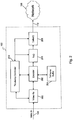
- FIG. 2 The components that are included in the first computing device 102 for processing the video signal 108, and that are not shown in FIG. 1 , are shown in FIG. 2 .
- Those components are a Video Rx 200, an Encoder 202, a TxFrame Buffer 204, a TxQ 206, a TxNetQ 208, and a TxLatency Controller 210.
- the components and their functionality are realized in hardware such as by one or more application-specific integrated circuits (ASICs) that provide all of the herein-described functionality.
- ASICs application-specific integrated circuits
- ASICs are used as a preferred hardware implementation according to the invention, it is possible to use one or more field-programmable gate arrays (FPGAs) and/or one or more other electronic components to provide the control, optimization, and synchronization functionality described herein for components 200, 202, 204, 206, 208, 210.
- FPGAs field-programmable gate arrays
- the components 200, 202, 204, 206, 208, 210 can together form a single module or card disposed within or otherwise made part of a larger system such as a server computer from which the video signal 108 comes.
- That server computer would include the typical parts of a server computer including at least one microprocessor, storage, and one or more input/output devices, and the server computer also would include the components 200, 202, 204, 206, 208, 210.
- These components could alternatively, and as shown in FIG. 2 , together form a single module or card or other type of electronic hardware system that is a separate stand-alone device that receives the video signal 108 and processes it as herein-described and then sends it out to the network 106 via the connection 110.
- the video signal 108 is received by the Video Rx 200.
- Video Rx 200 formats the video signal 108 such that it can be processed by the encoder 202.
- the encoder 202 processes the formatted video signal 108 into frames.
- the frames can be categorized into two categories, namely frames that are received from the Video Rx 200 and frames that were previously received by Video Rx 200.
- the frames can be formatted into tiles that are arranged in various dimensions, such as 8x8, 16x16, 64x64, and 128x128.
- the encoder 202 utilizes an algorithm to compress the tiles. Each tile is profiled to determine the type of data included in the formatted video signal 108. The algorithm is optimized to compress each tile based on the desired end-user experience.
- the encoder 202 stores the formatted video signal 108 in either the TxFrame Buffer 204 or the TxQ 206.
- the TxFrame Buffer 204 is used to store the video signal 108 when it is not compressed by the encoder 202.
- the TxQ 206 is used to store the video signal 108 when it is compressed into a tile by the encoder 202.
- the total amount of video signals stored in either the TxFrame Buffer 204 or the TxQ 206 is dependent upon the optimization of the algorithm used by the encoder 202.
- the TxQ 206 is configured to create a queue of the tiles (compressed video signal 108) as provided by the encoder 202.
- the TxQ 206 transfers each tile from the queue to the TxNetQ 208.
- the TxNetQ 208 converts each tile into packets of data for transmission across the communications network 106. These packets of data are queued for transmission over the communications network 106.
- the packets of data are transmitted from the TxNetQ 208 to the communications network 106 via the connection 110.
- the TxLatency Controller 210 is in communication with the Video Rx 200, the Encoder 202, the TxQ 206, and the TxNetQ 208.
- the TxLatency Controller 210 may be used to optimize the latency within the first computing device 102.
- the TxLatency Controller 210 is configured to utilize lossy compression and lossless compression.
- the TxLatency Controller 210 can perform lossy compression by instructing the Video Rx 200 or the TxQ 206 to discard frames.
- the TxLatency Controller 210 can also perform lossless compression by instructing the encoder 202 to increase or decrease the optimization of the algorithm in order to control the compression of each tile.
- the TxLatency Controller 210 can also specify a Quality-of-Service (QOS) setting on each tile prior to the conversion of the tiles into packets of data.
- QOS Quality-of-Service
- Those components are an RxNetQ 300, an RxQ 302, a Decoder 304, an RxFrame Buffer 306, a Video Tx 308, and an RxLatency Controller 310.
- these components and their functionality are realized in hardware such as by one or more application-specific integrated circuits (ASICs) that provide all of the herein-described functionality.
- ASICs application-specific integrated circuits
- ASICs are used as a preferred hardware implementation according to the invention, it is possible to use one or more field-programmable gate arrays (FPGAs) and/or one or more other electronic components to provide the control, optimization, and synchronization functionality described herein for components 300, 302, 304, 306, 308, 310.
- FPGAs field-programmable gate arrays
- the components 300, 302, 304, 306, 308, 310 can together form a single module or card disposed within or otherwise made part of a larger system such as a client computer (with a display device) to which the displayable video signal 114 goes.
- That client computer would include the typical parts of a client computer including at least one microprocessor, storage, and one or more input/output devices, and the client computer also would include the components 300, 302, 304, 306, 308, 310. These components could alternatively, and as shown in FIG.
- the display device could be a flat screen display or some other type of physical video display unit.
- the display device could be connected directly to the second computing device 104, or it could be connected to the separate client computer which receives the displayable video signal 114 from the second computing device 104.
- the second computing device 104 receives via the connection 112 packets of data transmitted from the first computing device 102 over the network 106. These packets of data are received by the RxNetQ 300.
- the RxNetQ 300 transfers the packets of data to the RxQ 302.
- the RxQ 302 creates a queue for each packet of data provided by the RxNetQ 300.
- the RxQ 302 subsequently transfers each packet of data from the queue to the decoder 304.
- the decoder 304 includes an algorithm for decompressing and decoded each packet of data into a frame.
- the decoder 304 subsequently transfers the frame to the RxFrame Buffer 306.
- the RxFrame Buffer 306 can store any number frames.
- the frames can be categorized into two categories, namely the frames converted for display on the display device associated with the second computing device 104 and the frame being decoded by the decoder 304.
- the Video Tx 308 takes the frame from the RxFrame Buffer 306 and converts the frame into a display video signal 114 for display on the display device.
- the RxLatency Controller 310 is used to control the latency within the second computing device 104.
- the RxLatency Controller 310 is in communication with the RxNetQ 300, the RxQ 302, the decoder 304, and the Video Tx 308.
- the RxLatency Controller 310 is configured to utilize lossy compression and lossless compression.
- the RxLatency Controller 310 can perform lossy compression by instructing the RxQ 302 or the decoder 304 to discard frames.
- the RxLatency Controller 310 can also perform lossless compression by instructing the Video Tx 308 to prepare a frame for display on the display device.
- a method 400 can be used to control and optimize latency over the communications network 106.
- the method 400 includes the following steps: identifying a condition 402, receiving a video signal 404, processing the video signal 406, determine whether the condition is met 408, and displaying the video signal 410.
- the system 100 is configured to identify at least one condition with the transmission of the video signal 108 from the first computing device 102 to the second computing device 104 at step 402.
- the video signal 108 is transmitted from the first computing device 102 to the second computing device 104.
- the video signal 108 is received by the second computing device 104 at step 404.
- the system 100 determines whether the at least one condition associated with the transmission of the video signal 108 is met at step 406. If the condition is met, the video signal 108 is converted into a displayable video signal 114 at step 408. If the condition is not met, the video signal 108 is not provided for display on the display device associated with the second computing device 104. The displayable video signal 114 is subsequently displayed on the display device.
- RxLatency Controller 310 can include at least four types of mechanisms for controlling latency. Each of these types of mechanisms is associated with a condition as identified at step 402 of the method 400.
- Rx Cut-Through is one type of mechanism used to control latency within the second computing device 104.
- RxCT can be a programmable threshold that defines when to begin displaying the displayable video signal 114 on the display device associated with the second computing device 104.
- the system 100 is configured to identify this programmable threshold as a condition at step 402 of the method 400. This condition may be defined in terms of total number of pixels, total number of lines, or a percentage of the total number of frames within the video signal 116. Once this condition is met (e.g., the total number of frame is exceeded), the Video Tx 308 displays the video signal 114 on the display device.
- the programmable threshold is typically initialized to cover twice the amount of standard network jitter to minimize the potential for an under-run in the transmission of the video signal 108.
- the decompressed frame (video signal 108) may not be stored in the RxFrame Buffer 306.
- the Video Tx 308 is unable to display the decompressed frame in its entirety on the display device 128. This is known as video tearing. Therefore, in operation, the Video Tx 308 checks whether the programmable threshold is exceeded prior to retrieving a frame from the RxFrame Buffer 306.
- the Video Tx 308 may begin to convert and display the frame on the display device. In a normal steady state, this will function as the normal mode of operation.
- the system 100 can also move out of the steady-state mode of operation when there is a change in latency and jitter in the communications network 106 or other events such as a major change in compressions ratio used by the first computing device 102 or the second computing device 104.
- the Video Tx 308 can determine whether the programmable threshold has not been met. In one instance, if the Video Tx 308 determines that the programmable threshold has not been met, the Video Tx 308 will replay the previously displayed video signal 114 on the display device associated with the second computing device 104. In another instance, if the RxFrame Buffer 306 does not include any frames, this means that the network jitter has likely exceed the programmable threshold.
- the programmable threshold can be increased to allow for an increase in jitter across the communications network 106.
- Various algorithms can be used to optimize this programmable threshold. For example, the programmable threshold can be increased by a specified value or it can be adjusted by an estimated increase in jitter across the communications network 106. This adjustment can be estimated by the amount that the programmable threshold was not exceeded.
- the programmable threshold can also be tuned by running a probability function on the number of frames stored in the RxFrame Buffer 306 when the Video Tx 308 looks to start retrieve the frame for display on the display device associated with the second computing device 104. This result can be defined as RxBuffSiz.
- the dynamic tuning of the programmable threshold is important to allow for tuning to changes in latency and jitter across the communications network 106.
- the RxCTmin can be a user-defined minimum value for the RxCT programmable threshold (e.g., 1/32 of a frame or 5 lines of a frame.) This can be translated based on the video resolution used by the display device associated with the second computing device 104.
- the RxCTmax can also be a user defined maximum value for the RxCT programmable threshold.
- an algorithm may be used to ensure that the frame retrieved for display by Video Tx 308 has been fully decoded.
- the RxCT programmable threshold By setting the RxCT programmable threshold to the RxCTmax as shown in step 5, a less aggressive reaction of a tear event can occur.
- Many different algorithms can also be used to tune the RxCT programmable threshold.
- a secondary use of tuning the RxCT programmable threshold is to allow for the tuning of the display timing of Video Tx 308.
- the display timing of Video Tx 308 can be setup to match the timing on Video Rx 200 of the first computing device 102. Due to clock drifts and slight variations in timing, the display time of Video Tx 308 can be slightly different than the timing of Video Rx 200, which will cause an under-run or overrun in the transmission of the video signal 108 (e.g., the first computing device 102 can send data faster or slower than the second computing device 104 can display).
- a comparison can be performed on each transmitted video signal 108 to add an extra clock to the display timing if Video Tx 308 detects that the average rate of decompressing frames into the RxFrame Buffer 306 is slower than the rate of displaying them. Changes to the display timing can take place slowly over a long period of time (10s to 1000s of seconds) to avoid the jittery display of the displayable video signal 114.
- This comparison can also ensure that low-level transients across the communications network 106 are not picked up, essentially debouncing changes when a programmable number changes are seen in succession. This debouncing performs as a smoothing and/or hysteresis function to ensure the resulting displayed images do not jitter due to constant tuning.
- Video Tx 308 can self tune itself to the timings of Video Tx 308 in a way that minimizes latency. In essence, the tuning of display timings seeks to keep the RxCT programmable threshold as low as possible.
- An example algorithm is shown below:
- the VSyncClocks min can be a user defined minimum value for VSyncClocks.
- the VSyncClocks max can be a user defined maximum value for VSyncClocks.
- the VSyncClocks can be a non-zero integer value.
- Receive/Discard is another type of mechanism used to control latency within the second computing device 104.
- Receive/Discard can be also be a programmable threshold that defines when to begin displaying a displayable video signal 114 on the display device associated with the second computing device 104.
- system 100 is configured to identify the programmable threshold as a condition. Once this condition is met, the Video Tx 308 can either skip or discard the frame stored in the RxFrame Buffer 306 or simply replay the last displayable video signal 114 displayed on the display device. This functionality allows the second computing device 104 to catch up by dropping a frame without that frame being visible to an end-user.
- Transmit/Discard is another type of mechanism used to control latency within the first computing device 102 and the second computing device 104.
- Transmit/Discard can be a programmable threshold that defines a total number of frames within the video signal 108. Ideally, this threshold should be less than one when operating in a low latency communications network 106. In contrast, on a high latency communications network 106, the threshold can be set to a few frames. For example, if the latency over the communications network 106 is 50 milliseconds (ms) and the video signal 108 is 16 milliseconds (ms), the programmable threshold could be set to three or four frames.
- jitter in the communications network 106 can cause the video signal 108 to be buffered in the TxQ 206 in the first computing device 102. This jitter can be due to changes on the communications network 106, thereby causing less or more bandwidth to be available or lower rates of compression causing the available network bandwidth to be exceeded.
- the TxQ 206 keeps a count of the number of frames in the video signal 108. This value can be known as TxQSiz.
- the first computing device 102 receives periodic updates from the second computing device 104 of which frame it is currently displaying. This value can be known as RxCurFr.
- the TxLatencyController 210 uses these two pieces of information, TxQSiz and RxCurFr, together with the current frame being received, also known as TxCurFr, to estimate the total number of frames in transit. This is designated as TxLatency.
- the MaxTxLatency can be a set value or can be dynamically estimated by round-trip from the first computing device 102 to the second computing device 104. This allows for tuning the amount of frames in the TxQ 206 to specific conditions of the communications network 106.
- Compression/NetworkQ is another type of mechanism used to control latency within the first computing device 102 and the second computing device 104.
- Compression/NetworkQ can be a priority level for processing the video signal 108 that is transmitted between the first computing device 102 and the second computing device 104.
- Compression/NetworkQ is typically used with the encoder 202 of the first computing device 102 and it utilizes a combination of compression techniques to process the video signal 108 to optimize compression while minimizing visual defects.
- the system 100 is configured to identify the priority level as a condition. Once this condition is met, the video signal 108 is converted into packets of data for transfer over the communications network 106 based on its priority level. For example, audio signals can be set to the highest priority followed by video signals.
- the encoder 202 can process a frame in real-time.
- the encoder 202 can also perform temporal as well as spatial compression using real-time techniques.
- the system 100 can also be used for audio and video synchronization.
- the encoder 202 can time stamp incoming audio signals prior to transmission to the second computing device 102.
- the decoder 304 stamps the incoming audio signals to indicate the time of receipt.
- the first and second timestamps of the audio signal can be compared to determine whether any adjustments should be made to synchronize the audio signal with the video signal in order to maintain lip-sync between the audio and video.
- the encoder 202 and the decoder 304 can be tuned to replay and/or drop frames in order to allow synchronization between the audio signal and the video signal.
- a key aspect of this algorithm is to ensure that the damping factors allows the this tuning to be performed in a manner that a user cannot visually or audibly notice changes during normal network conditions, and gracefully handle abnormal conditions.
- a 32-bit timer value could give a +/- 14 second window for video at high definition resolutions (1920x1200), which is more than adequate for any difference that should arise between the audio and video synchronization.
- a sub one-second delay can be expected in this configuration unless there are network connectivity issues. It is also expected that the difference between the audio and video synchronization can be due to network effects between the first computing device 102 and the second computing device 104. Therefore, in this configuration, video frames will not unnecessarily be dropped due to a lack of synchronization with the audio signal.
- audio and video synchronization is critical, such as the broadcast industry with audio and video post production, it is possible to align the audio and video signals at the first computing device 102 prior to transmission to the second computing device 104.
- audio signals can be introduced into the packets of data prior to transmission from the first computing device 102 to the second computing device 104. Because both audio and video signals are being sent over the same network connection, this arrangement will remove latency differences that may occur at the computer server or across the communications network 106.
- each of the first and second computing devices 102, 104 is realized in hardware such as with one or more application-specific integrated circuits (ASICs). That is, for all of the functionality described herein for the first computing device 102, one or more ASICs can provide all of that functionality, and, for all of the functionality described herein for the second computing device 104, one or more ASICs can provide all of that functionality. While one or more ASICs are used as the preferred hardware implementation according to the invention, it is possible to use one or more field-programmable gate arrays (FPGAs) and/or one or more other electronic components.
- FPGAs field-programmable gate arrays
- Each ASIC, FPGA, and other component can include one or more processors (such as 32-bit processors), storage such as memory (including ROM, RAM, EEPROM, Flash), and other large electronic building blocks, and as is typical a hardware description language (HDL) such as Verilog or VHDL can be used by the designer(s) of the ASICs or other components to describe the functionality of the ASICs or other components.
- processors such as 32-bit processors
- storage such as memory (including ROM, RAM, EEPROM, Flash), and other large electronic building blocks, and as is typical a hardware description language (HDL) such as Verilog or VHDL can be used by the designer(s) of the ASICs or other components to describe the functionality of the ASICs or other components.
- HDL hardware description language
- each of the TxLatency Controller 210 and the RxLatency Controller 310 can include embedded software or otherwise have software support to control hardware functionality, particularly when longer-term averages are being computed.
- each of these server and client computers typically will include at least one processor such as a microprocessor, storage, and one or more input/output devices.
- the storage can contain software code or instructions which, when executed by the processor(s), causes the processor(s) to perform a variety of functions.
- the storage is one or more of any kind of physical computer-readable media such as magnetic storage media (e.g., hard disks, floppy disks, and magnetic tape), optical storage media (e.g., compact discs or CDs, digital video discs or DVDs, compact disc read only memories or CD-ROMs), magnetooptical storage media, read-only memory or ROM, random-access memory or RAM, and flash memory devices.
- the input/output devices can include a keyboard, a mouse or other pointing device, a display, etc.
Landscapes
- Engineering & Computer Science (AREA)
- Theoretical Computer Science (AREA)
- Physics & Mathematics (AREA)
- General Physics & Mathematics (AREA)
- Computer Hardware Design (AREA)
- Human Computer Interaction (AREA)
- General Engineering & Computer Science (AREA)
- Two-Way Televisions, Distribution Of Moving Picture Or The Like (AREA)
Claims (6)
- Verfahren zum Steuern und Optimieren von Latenz über einem Kommunikationsnetzwerk (106) von einer ersten Datenverarbeitungsvorrichtung (102) zu einer zweiten Datenverarbeitungsvorrichtung (104), das die folgenden Schritte umfasst:Erstellen einer Schwelle (MaxTxLatency), die mit der Übertragung eines Videosignals (108), das eine Vielzahl von Einzelbildern umfasst, von der ersten Datenverarbeitungsvorrichtung zur zweiten Datenverarbeitungsvorrichtung assoziiert ist, wobei die Schwelle auf einer Anzahl der Vielzahl von im Transit befindlichen Einzelbildern zwischen der ersten und der zweiten Datenverarbeitungsvorrichtung basiert, die die Latenz verursachen, wobei jedes Einzelbild in Kacheln formatiert ist;Übertragen, zur zweiten Datenverarbeitungsvorrichtung, von einem oder mehreren der Vielzahl von Einzelbildern über das Kommunikationsnetzwerk durch die erste Datenverarbeitungsvorrichtung;Messen einer Anzahl von Einzelbildern der Vielzahl von Einzelbildern in dem Videosignal in der ersten Datenverarbeitungsvorrichtung, wobei das Messen das Mitzählen einer Anzahl der Einzelbilder in einer Warteschlange (TxQ) der ersten Datenverarbeitungsvorrichtung umfasst;Identifizieren, welches Einzelbild (RxCurFr) der Vielzahl von Einzelbildern aktuell auf einer Anzeigevorrichtung, die mit der zweiten Datenverarbeitungsvorrichtung assoziiert ist, angezeigt wird, wobei das Identifizieren umfasst, dass die erste Datenverarbeitungsvorrichtung periodische Aktualisierungen von der zweiten Datenverarbeitungsvorrichtung hinsichtlich des Einzelbilds der Vielzahl von Einzelbildern, das aktuell angezeigt wird, empfängt;Verwenden der Anzahl (TxQSiz) von Einzelbildern in der Warteschlange und des aktuell angezeigten Einzelbilds (RxCurFr) zusammen mit einem Einzelbild der Vielzahl von Einzelbildern, das aktuell an der ersten Datenverarbeitungsvorrichtung empfangen wird (TxCurFr), zum Bestimmen einer geschätzten Anzahl (TxLatency) von im Transit befindlichen Einzelbildern;Bestimmen, ob die geschätzte Anzahl (TxLatency) von im Transit befindlichen Einzelbildern die Schwelle (MaxTxLatency) übersteigt; undVerwerfen eines ältesten Einzelbilds in der Warteschlange (TxQ) der ersten Datenverarbeitungsvorrichtung, wenn die geschätzte Anzahl (TxLatency) von im Transit befindlichen Einzelbildern die Schwelle (MaxTxLatency) übersteigt.
- Verfahren nach Anspruch 1, das ferner das Anzeigen eines oder mehrerer der Vielzahl von Einzelbildern auf einer Anzeigevorrichtung der zweiten Datenverarbeitungsvorrichtung umfasst.
- Verfahren nach Anspruch 1, wobei das Videosignal die Ausgabe einer Graphikkarte ist, die mit der ersten Datenverarbeitungsvorrichtung assoziiert ist.
- Verfahren nach Anspruch 3, wobei die Graphikkarte aus einer digitalen Videoschnittstelle, einer virtuellen Graphikschnittstelle und einer Hochdefinitions-Multimediaschnittstelle ausgewählt ist.
- Verfahren nach Anspruch 1, wobei das Videosignal die Ausgabe eines Softwaretreibers ist, der mit der ersten Datenverarbeitungsvorrichtung assoziiert ist.
- Verfahren nach Anspruch 1, wobei das Verfahren ferner das Einstellen der Komprimierung von einem oder mehreren der Vielzahl von Einzelbildern umfasst.
Applications Claiming Priority (2)
| Application Number | Priority Date | Filing Date | Title |
|---|---|---|---|
| US12/984,697 US8589509B2 (en) | 2011-01-05 | 2011-01-05 | Controlling and optimizing system latency |
| PCT/IB2011/003277 WO2012093283A1 (en) | 2011-01-05 | 2011-12-29 | Controlling and optimizing system latency |
Publications (2)
| Publication Number | Publication Date |
|---|---|
| EP2661680A1 EP2661680A1 (de) | 2013-11-13 |
| EP2661680B1 true EP2661680B1 (de) | 2017-06-07 |
Family
ID=45569698
Family Applications (1)
| Application Number | Title | Priority Date | Filing Date |
|---|---|---|---|
| EP11817239.4A Active EP2661680B1 (de) | 2011-01-05 | 2011-12-29 | Steuerung und optimierung von systemlatenz |
Country Status (4)
| Country | Link |
|---|---|
| US (1) | US8589509B2 (de) |
| EP (1) | EP2661680B1 (de) |
| DK (1) | DK2661680T3 (de) |
| WO (1) | WO2012093283A1 (de) |
Families Citing this family (9)
| Publication number | Priority date | Publication date | Assignee | Title |
|---|---|---|---|---|
| US9235905B2 (en) | 2013-03-13 | 2016-01-12 | Ologn Technologies Ag | Efficient screen image transfer |
| US10158868B2 (en) * | 2013-10-15 | 2018-12-18 | Nvidia Corporation | Systems and methods to limit lag between a client and a server for remote computing |
| IN2014CH00105A (de) | 2014-01-09 | 2015-07-10 | Inmobi Pte Ltd | |
| US10387993B2 (en) | 2017-09-29 | 2019-08-20 | Intel Corporation | Fault-tolerant graphics display engine |
| CN108989879B (zh) | 2018-08-28 | 2021-06-15 | 广州视源电子科技股份有限公司 | 投屏的控制方法、装置和系统 |
| US20200137134A1 (en) * | 2018-10-31 | 2020-04-30 | Ati Technologies Ulc | Multi-session low latency encoding |
| US11005909B2 (en) | 2019-08-30 | 2021-05-11 | Rovi Guides, Inc. | Systems and methods for providing content during reduced streaming quality |
| US10986378B2 (en) * | 2019-08-30 | 2021-04-20 | Rovi Guides, Inc. | Systems and methods for providing content during reduced streaming quality |
| US11184648B2 (en) | 2019-08-30 | 2021-11-23 | Rovi Guides, Inc. | Systems and methods for providing content during reduced streaming quality |
Family Cites Families (35)
| Publication number | Priority date | Publication date | Assignee | Title |
|---|---|---|---|---|
| US6400996B1 (en) | 1999-02-01 | 2002-06-04 | Steven M. Hoffberg | Adaptive pattern recognition based control system and method |
| US6418424B1 (en) | 1991-12-23 | 2002-07-09 | Steven M. Hoffberg | Ergonomic man-machine interface incorporating adaptive pattern recognition based control system |
| US5742840A (en) | 1995-08-16 | 1998-04-21 | Microunity Systems Engineering, Inc. | General purpose, multiple precision parallel operation, programmable media processor |
| US6275867B1 (en) | 1995-09-12 | 2001-08-14 | International Business Machines Corporation | Operation-partitioned off-loading of operations in a distributed environment |
| US5917553A (en) * | 1996-10-22 | 1999-06-29 | Fox Sports Productions Inc. | Method and apparatus for enhancing the broadcast of a live event |
| US6202060B1 (en) | 1996-10-29 | 2001-03-13 | Bao Q. Tran | Data management system |
| US5995490A (en) * | 1996-12-13 | 1999-11-30 | Siemens Information And Communication Networks, Inc. | Method and system for integrating video and data transfers in a multimedia session |
| US6157935A (en) | 1996-12-17 | 2000-12-05 | Tran; Bao Q. | Remote data access and management system |
| JPH10232788A (ja) | 1996-12-17 | 1998-09-02 | Fujitsu Ltd | 信号処理装置及びソフトウェア |
| US7068680B1 (en) | 1999-10-01 | 2006-06-27 | Accenture Llp | Communication service architectures for netcentric computing systems |
| US7020697B1 (en) | 1999-10-01 | 2006-03-28 | Accenture Llp | Architectures for netcentric computing systems |
| US7047196B2 (en) | 2000-06-08 | 2006-05-16 | Agiletv Corporation | System and method of voice recognition near a wireline node of a network supporting cable television and/or video delivery |
| US20020184208A1 (en) | 2001-04-24 | 2002-12-05 | Saul Kato | System and method for dynamically generating content on a portable computing device |
| US6842433B2 (en) | 2001-04-24 | 2005-01-11 | Wideray Corporation | System and method for communicating information from a computerized distributor to portable computing devices |
| US7072975B2 (en) | 2001-04-24 | 2006-07-04 | Wideray Corporation | Apparatus and method for communicating information to portable computing devices |
| US7012893B2 (en) * | 2001-06-12 | 2006-03-14 | Smartpackets, Inc. | Adaptive control of data packet size in networks |
| US7086055B2 (en) | 2001-08-02 | 2006-08-01 | Hewlett-Packard Development Company, L.P. | Computer system and method for increased processing power by communicating with non-computer devices |
| WO2003017577A1 (en) * | 2001-08-09 | 2003-02-27 | Matsushita Electric Industrial Co., Ltd. | Transmission apparatus and transmission method |
| US6845230B2 (en) | 2001-10-26 | 2005-01-18 | Ibiquity Digital Corporation | System and method for a push-pull gateway-directed digital receiver |
| US7592829B2 (en) | 2002-12-02 | 2009-09-22 | Silverbrook Research Pty Ltd | On-chip storage of secret information as inverse pair |
| US10201760B2 (en) * | 2002-12-10 | 2019-02-12 | Sony Interactive Entertainment America Llc | System and method for compressing video based on detected intraframe motion |
| US7701915B2 (en) * | 2003-06-27 | 2010-04-20 | Nokia Corporation | Method in a communication system, a communication system and a communication device |
| US20050165617A1 (en) | 2004-01-28 | 2005-07-28 | Patterson Brian L. | Transaction-based storage operations |
| US7259758B2 (en) | 2004-06-21 | 2007-08-21 | Microsoft Corporation | System and method for reducing latency in display of computer-generated graphics |
| US7516255B1 (en) | 2005-03-30 | 2009-04-07 | Teradici Corporation | Method and apparatus for providing a low-latency connection between a data processor and a remote graphical user interface over a network |
| US7936819B2 (en) * | 2005-07-08 | 2011-05-03 | Tag Networks, Inc. | Video encoder with latency control |
| EP1788773A1 (de) | 2005-11-18 | 2007-05-23 | Alcatel Lucent | Verfahren und Vorrichtungen zur Anforderung eines Medienpostens und zur Voraberstellung eines Tokens |
| JP2007251553A (ja) * | 2006-03-15 | 2007-09-27 | Matsushita Electric Ind Co Ltd | リアルタイム処理装置及びその方法 |
| US8952974B2 (en) * | 2006-04-20 | 2015-02-10 | Cisco Technology, Inc. | Latency reduction in a display device |
| US8704833B2 (en) * | 2007-06-06 | 2014-04-22 | Apple Inc. | Method and apparatus for displaying a video signal on a computer system |
| JP5593596B2 (ja) * | 2008-02-04 | 2014-09-24 | ソニー株式会社 | 映像信号送信装置および映像信号送信方法 |
| US20100014777A1 (en) * | 2008-07-19 | 2010-01-21 | Headplay (Barbados) Inc. | System and method for improving the quality of compressed video signals by smoothing the entire frame and overlaying preserved detail |
| JP2011043775A (ja) * | 2009-08-24 | 2011-03-03 | Nec Lcd Technologies Ltd | 画像表示装置及び該画像表示装置に用いられる映像信号処理方法 |
| US20110222556A1 (en) * | 2010-03-10 | 2011-09-15 | Shefler David | Method circuit and system for adaptive transmission and reception of video |
| US8941706B2 (en) * | 2010-04-07 | 2015-01-27 | Apple Inc. | Image processing for a dual camera mobile device |
-
2011
- 2011-01-05 US US12/984,697 patent/US8589509B2/en active Active
- 2011-12-29 DK DK11817239.4T patent/DK2661680T3/en active
- 2011-12-29 WO PCT/IB2011/003277 patent/WO2012093283A1/en not_active Ceased
- 2011-12-29 EP EP11817239.4A patent/EP2661680B1/de active Active
Non-Patent Citations (1)
| Title |
|---|
| None * |
Also Published As
| Publication number | Publication date |
|---|---|
| WO2012093283A1 (en) | 2012-07-12 |
| US20120173662A1 (en) | 2012-07-05 |
| US8589509B2 (en) | 2013-11-19 |
| EP2661680A1 (de) | 2013-11-13 |
| DK2661680T3 (en) | 2017-08-21 |
Similar Documents
| Publication | Publication Date | Title |
|---|---|---|
| US8589509B2 (en) | Controlling and optimizing system latency | |
| US7844848B1 (en) | Method and apparatus for managing remote display updates | |
| US7516255B1 (en) | Method and apparatus for providing a low-latency connection between a data processor and a remote graphical user interface over a network | |
| US8320446B2 (en) | System for transmission of synchronous video with compression through channels with varying transmission delay | |
| US7672005B1 (en) | Methods and apparatus for scan block caching | |
| EP2752002B1 (de) | Systeme und verfahren zur steuerung der kodierung eines segmentierten medienstroms anhand von segmentsendezeiten | |
| EP3503570A1 (de) | Verfahren zur übertragung von videorahmen aus einem video-stream zu einer anzeige und zugehörige vorrichtung | |
| US20060256822A1 (en) | Apparatus for synchronization of digital multimedia data communicated over wired media | |
| EP1475922B1 (de) | Datenverarbeitungsvorrichtung, -system und -verfahren, Speichermedium und Rechnerprogramm für das Datenverarbeitungsverfahren | |
| WO2005001702A3 (en) | Synchronized transmission of audio and video data from a computer to a client via an interface | |
| US9807408B2 (en) | Control mechanism for video output | |
| US8467444B2 (en) | Information processing system, information processing apparatus, information processing method, and program | |
| EP2945393A1 (de) | Wiedergabevorrichtung und datenwiedergabeverfahren | |
| US20130166769A1 (en) | Receiving device, screen frame transmission system and method | |
| WO2013112637A1 (en) | System and method for maintaining integrity of audio data in a multiplexed audio/video stream over a low-latency network connection | |
| US7187697B1 (en) | Method and system for delivering MPEG video over bursty communication channels | |
| EP3281317B1 (de) | Mehrlagiges rahmenwerk zur zeitsynchronisierung | |
| WO2010062471A2 (en) | Methods and systems for improving network response during channel change | |
| EP1913719A1 (de) | Datenstromsynchronisierung | |
| US8422518B2 (en) | Managing transmit jitter for multi-format digital audio transmission | |
| US7668094B2 (en) | Time-offset regulated method and system for synchronization and rate control of media data | |
| US12126701B2 (en) | Compensating for interruptions in a wireless connection | |
| CN102547204B (zh) | 接收装置、荧幕画面传输系统以及其传输方法 | |
| CN115767183B (zh) | 抖动缓冲队列的调整方法、装置、介质和计算设备 | |
| GB2492749A (en) | Synchronising Wireless Video Data Nodes |
Legal Events
| Date | Code | Title | Description |
|---|---|---|---|
| PUAI | Public reference made under article 153(3) epc to a published international application that has entered the european phase |
Free format text: ORIGINAL CODE: 0009012 |
|
| 17P | Request for examination filed |
Effective date: 20130611 |
|
| AK | Designated contracting states |
Kind code of ref document: A1 Designated state(s): AL AT BE BG CH CY CZ DE DK EE ES FI FR GB GR HR HU IE IS IT LI LT LU LV MC MK MT NL NO PL PT RO RS SE SI SK SM TR |
|
| DAX | Request for extension of the european patent (deleted) | ||
| 17Q | First examination report despatched |
Effective date: 20150619 |
|
| RAP1 | Party data changed (applicant data changed or rights of an application transferred) |
Owner name: BLACK BOX DEVELOPMENT SERVICES LIMITED |
|
| RAP1 | Party data changed (applicant data changed or rights of an application transferred) |
Owner name: BLACK BOX SOFTWARE DEVELOPMENT SERVICES LIMITED |
|
| STAA | Information on the status of an ep patent application or granted ep patent |
Free format text: STATUS: EXAMINATION IS IN PROGRESS |
|
| GRAP | Despatch of communication of intention to grant a patent |
Free format text: ORIGINAL CODE: EPIDOSNIGR1 |
|
| STAA | Information on the status of an ep patent application or granted ep patent |
Free format text: STATUS: GRANT OF PATENT IS INTENDED |
|
| INTG | Intention to grant announced |
Effective date: 20170213 |
|
| GRAS | Grant fee paid |
Free format text: ORIGINAL CODE: EPIDOSNIGR3 |
|
| GRAA | (expected) grant |
Free format text: ORIGINAL CODE: 0009210 |
|
| STAA | Information on the status of an ep patent application or granted ep patent |
Free format text: STATUS: THE PATENT HAS BEEN GRANTED |
|
| AK | Designated contracting states |
Kind code of ref document: B1 Designated state(s): AL AT BE BG CH CY CZ DE DK EE ES FI FR GB GR HR HU IE IS IT LI LT LU LV MC MK MT NL NO PL PT RO RS SE SI SK SM TR |
|
| REG | Reference to a national code |
Ref country code: GB Ref legal event code: FG4D |
|
| GRAA | (expected) grant |
Free format text: ORIGINAL CODE: 0009210 |
|
| REG | Reference to a national code |
Ref country code: CH Ref legal event code: EP Ref country code: AT Ref legal event code: REF Ref document number: 899688 Country of ref document: AT Kind code of ref document: T Effective date: 20170615 |
|
| REG | Reference to a national code |
Ref country code: IE Ref legal event code: FG4D |
|
| REG | Reference to a national code |
Ref country code: NL Ref legal event code: FP |
|
| REG | Reference to a national code |
Ref country code: DE Ref legal event code: R096 Ref document number: 602011038586 Country of ref document: DE |
|
| REG | Reference to a national code |
Ref country code: DK Ref legal event code: T3 Effective date: 20170817 |
|
| REG | Reference to a national code |
Ref country code: SE Ref legal event code: TRGR |
|
| REG | Reference to a national code |
Ref country code: NO Ref legal event code: T2 Effective date: 20170607 |
|
| REG | Reference to a national code |
Ref country code: LT Ref legal event code: MG4D |
|
| PG25 | Lapsed in a contracting state [announced via postgrant information from national office to epo] |
Ref country code: LT Free format text: LAPSE BECAUSE OF FAILURE TO SUBMIT A TRANSLATION OF THE DESCRIPTION OR TO PAY THE FEE WITHIN THE PRESCRIBED TIME-LIMIT Effective date: 20170607 Ref country code: GR Free format text: LAPSE BECAUSE OF FAILURE TO SUBMIT A TRANSLATION OF THE DESCRIPTION OR TO PAY THE FEE WITHIN THE PRESCRIBED TIME-LIMIT Effective date: 20170908 Ref country code: ES Free format text: LAPSE BECAUSE OF FAILURE TO SUBMIT A TRANSLATION OF THE DESCRIPTION OR TO PAY THE FEE WITHIN THE PRESCRIBED TIME-LIMIT Effective date: 20170607 Ref country code: HR Free format text: LAPSE BECAUSE OF FAILURE TO SUBMIT A TRANSLATION OF THE DESCRIPTION OR TO PAY THE FEE WITHIN THE PRESCRIBED TIME-LIMIT Effective date: 20170607 |
|
| REG | Reference to a national code |
Ref country code: FR Ref legal event code: PLFP Year of fee payment: 7 |
|
| REG | Reference to a national code |
Ref country code: AT Ref legal event code: MK05 Ref document number: 899688 Country of ref document: AT Kind code of ref document: T Effective date: 20170607 |
|
| PG25 | Lapsed in a contracting state [announced via postgrant information from national office to epo] |
Ref country code: RS Free format text: LAPSE BECAUSE OF FAILURE TO SUBMIT A TRANSLATION OF THE DESCRIPTION OR TO PAY THE FEE WITHIN THE PRESCRIBED TIME-LIMIT Effective date: 20170607 Ref country code: LV Free format text: LAPSE BECAUSE OF FAILURE TO SUBMIT A TRANSLATION OF THE DESCRIPTION OR TO PAY THE FEE WITHIN THE PRESCRIBED TIME-LIMIT Effective date: 20170607 Ref country code: BG Free format text: LAPSE BECAUSE OF FAILURE TO SUBMIT A TRANSLATION OF THE DESCRIPTION OR TO PAY THE FEE WITHIN THE PRESCRIBED TIME-LIMIT Effective date: 20170907 |
|
| PG25 | Lapsed in a contracting state [announced via postgrant information from national office to epo] |
Ref country code: AT Free format text: LAPSE BECAUSE OF FAILURE TO SUBMIT A TRANSLATION OF THE DESCRIPTION OR TO PAY THE FEE WITHIN THE PRESCRIBED TIME-LIMIT Effective date: 20170607 Ref country code: SK Free format text: LAPSE BECAUSE OF FAILURE TO SUBMIT A TRANSLATION OF THE DESCRIPTION OR TO PAY THE FEE WITHIN THE PRESCRIBED TIME-LIMIT Effective date: 20170607 Ref country code: RO Free format text: LAPSE BECAUSE OF FAILURE TO SUBMIT A TRANSLATION OF THE DESCRIPTION OR TO PAY THE FEE WITHIN THE PRESCRIBED TIME-LIMIT Effective date: 20170607 Ref country code: EE Free format text: LAPSE BECAUSE OF FAILURE TO SUBMIT A TRANSLATION OF THE DESCRIPTION OR TO PAY THE FEE WITHIN THE PRESCRIBED TIME-LIMIT Effective date: 20170607 Ref country code: CZ Free format text: LAPSE BECAUSE OF FAILURE TO SUBMIT A TRANSLATION OF THE DESCRIPTION OR TO PAY THE FEE WITHIN THE PRESCRIBED TIME-LIMIT Effective date: 20170607 |
|
| PG25 | Lapsed in a contracting state [announced via postgrant information from national office to epo] |
Ref country code: IS Free format text: LAPSE BECAUSE OF FAILURE TO SUBMIT A TRANSLATION OF THE DESCRIPTION OR TO PAY THE FEE WITHIN THE PRESCRIBED TIME-LIMIT Effective date: 20171007 Ref country code: IT Free format text: LAPSE BECAUSE OF FAILURE TO SUBMIT A TRANSLATION OF THE DESCRIPTION OR TO PAY THE FEE WITHIN THE PRESCRIBED TIME-LIMIT Effective date: 20170607 Ref country code: SM Free format text: LAPSE BECAUSE OF FAILURE TO SUBMIT A TRANSLATION OF THE DESCRIPTION OR TO PAY THE FEE WITHIN THE PRESCRIBED TIME-LIMIT Effective date: 20170607 Ref country code: PL Free format text: LAPSE BECAUSE OF FAILURE TO SUBMIT A TRANSLATION OF THE DESCRIPTION OR TO PAY THE FEE WITHIN THE PRESCRIBED TIME-LIMIT Effective date: 20170607 |
|
| REG | Reference to a national code |
Ref country code: DE Ref legal event code: R097 Ref document number: 602011038586 Country of ref document: DE |
|
| PLBE | No opposition filed within time limit |
Free format text: ORIGINAL CODE: 0009261 |
|
| STAA | Information on the status of an ep patent application or granted ep patent |
Free format text: STATUS: NO OPPOSITION FILED WITHIN TIME LIMIT |
|
| 26N | No opposition filed |
Effective date: 20180308 |
|
| PG25 | Lapsed in a contracting state [announced via postgrant information from national office to epo] |
Ref country code: SI Free format text: LAPSE BECAUSE OF FAILURE TO SUBMIT A TRANSLATION OF THE DESCRIPTION OR TO PAY THE FEE WITHIN THE PRESCRIBED TIME-LIMIT Effective date: 20170607 |
|
| REG | Reference to a national code |
Ref country code: CH Ref legal event code: PL |
|
| PG25 | Lapsed in a contracting state [announced via postgrant information from national office to epo] |
Ref country code: LU Free format text: LAPSE BECAUSE OF NON-PAYMENT OF DUE FEES Effective date: 20171229 Ref country code: MT Free format text: LAPSE BECAUSE OF NON-PAYMENT OF DUE FEES Effective date: 20171229 |
|
| PG25 | Lapsed in a contracting state [announced via postgrant information from national office to epo] |
Ref country code: CH Free format text: LAPSE BECAUSE OF NON-PAYMENT OF DUE FEES Effective date: 20171231 Ref country code: LI Free format text: LAPSE BECAUSE OF NON-PAYMENT OF DUE FEES Effective date: 20171231 |
|
| PG25 | Lapsed in a contracting state [announced via postgrant information from national office to epo] |
Ref country code: MC Free format text: LAPSE BECAUSE OF FAILURE TO SUBMIT A TRANSLATION OF THE DESCRIPTION OR TO PAY THE FEE WITHIN THE PRESCRIBED TIME-LIMIT Effective date: 20170607 Ref country code: HU Free format text: LAPSE BECAUSE OF FAILURE TO SUBMIT A TRANSLATION OF THE DESCRIPTION OR TO PAY THE FEE WITHIN THE PRESCRIBED TIME-LIMIT; INVALID AB INITIO Effective date: 20111229 |
|
| PG25 | Lapsed in a contracting state [announced via postgrant information from national office to epo] |
Ref country code: CY Free format text: LAPSE BECAUSE OF NON-PAYMENT OF DUE FEES Effective date: 20170607 |
|
| PG25 | Lapsed in a contracting state [announced via postgrant information from national office to epo] |
Ref country code: MK Free format text: LAPSE BECAUSE OF FAILURE TO SUBMIT A TRANSLATION OF THE DESCRIPTION OR TO PAY THE FEE WITHIN THE PRESCRIBED TIME-LIMIT Effective date: 20170607 |
|
| PG25 | Lapsed in a contracting state [announced via postgrant information from national office to epo] |
Ref country code: TR Free format text: LAPSE BECAUSE OF FAILURE TO SUBMIT A TRANSLATION OF THE DESCRIPTION OR TO PAY THE FEE WITHIN THE PRESCRIBED TIME-LIMIT Effective date: 20170607 |
|
| PG25 | Lapsed in a contracting state [announced via postgrant information from national office to epo] |
Ref country code: PT Free format text: LAPSE BECAUSE OF FAILURE TO SUBMIT A TRANSLATION OF THE DESCRIPTION OR TO PAY THE FEE WITHIN THE PRESCRIBED TIME-LIMIT Effective date: 20170607 |
|
| PG25 | Lapsed in a contracting state [announced via postgrant information from national office to epo] |
Ref country code: AL Free format text: LAPSE BECAUSE OF FAILURE TO SUBMIT A TRANSLATION OF THE DESCRIPTION OR TO PAY THE FEE WITHIN THE PRESCRIBED TIME-LIMIT Effective date: 20170607 |
|
| P01 | Opt-out of the competence of the unified patent court (upc) registered |
Effective date: 20230425 |
|
| PGFP | Annual fee paid to national office [announced via postgrant information from national office to epo] |
Ref country code: NL Payment date: 20251112 Year of fee payment: 15 |
|
| PGFP | Annual fee paid to national office [announced via postgrant information from national office to epo] |
Ref country code: DE Payment date: 20251104 Year of fee payment: 15 |
|
| PGFP | Annual fee paid to national office [announced via postgrant information from national office to epo] |
Ref country code: GB Payment date: 20251114 Year of fee payment: 15 |
|
| PGFP | Annual fee paid to national office [announced via postgrant information from national office to epo] |
Ref country code: NO Payment date: 20251210 Year of fee payment: 15 |
|
| PGFP | Annual fee paid to national office [announced via postgrant information from national office to epo] |
Ref country code: FI Payment date: 20251211 Year of fee payment: 15 Ref country code: DK Payment date: 20251212 Year of fee payment: 15 |
|
| PGFP | Annual fee paid to national office [announced via postgrant information from national office to epo] |
Ref country code: FR Payment date: 20251110 Year of fee payment: 15 |
|
| PGFP | Annual fee paid to national office [announced via postgrant information from national office to epo] |
Ref country code: BE Payment date: 20251117 Year of fee payment: 15 |
|
| PGFP | Annual fee paid to national office [announced via postgrant information from national office to epo] |
Ref country code: SE Payment date: 20251112 Year of fee payment: 15 |
|
| PGFP | Annual fee paid to national office [announced via postgrant information from national office to epo] |
Ref country code: IE Payment date: 20251111 Year of fee payment: 15 |