EP2660963B1 - Intelligent currect analysis for resonant converters - Google Patents
Intelligent currect analysis for resonant converters Download PDFInfo
- Publication number
- EP2660963B1 EP2660963B1 EP13405055.8A EP13405055A EP2660963B1 EP 2660963 B1 EP2660963 B1 EP 2660963B1 EP 13405055 A EP13405055 A EP 13405055A EP 2660963 B1 EP2660963 B1 EP 2660963B1
- Authority
- EP
- European Patent Office
- Prior art keywords
- component
- resonant converter
- sample
- primary
- triangular
- Prior art date
- Legal status (The legal status is an assumption and is not a legal conclusion. Google has not performed a legal analysis and makes no representation as to the accuracy of the status listed.)
- Active
Links
Images


Classifications
-
- H—ELECTRICITY
- H02—GENERATION; CONVERSION OR DISTRIBUTION OF ELECTRIC POWER
- H02M—APPARATUS FOR CONVERSION BETWEEN AC AND AC, BETWEEN AC AND DC, OR BETWEEN DC AND DC, AND FOR USE WITH MAINS OR SIMILAR POWER SUPPLY SYSTEMS; CONVERSION OF DC OR AC INPUT POWER INTO SURGE OUTPUT POWER; CONTROL OR REGULATION THEREOF
- H02M3/00—Conversion of DC power input into DC power output
- H02M3/22—Conversion of DC power input into DC power output with intermediate conversion into AC
- H02M3/24—Conversion of DC power input into DC power output with intermediate conversion into AC by static converters
- H02M3/28—Conversion of DC power input into DC power output with intermediate conversion into AC by static converters using discharge tubes with control electrode or semiconductor devices with control electrode to produce the intermediate AC
- H02M3/325—Conversion of DC power input into DC power output with intermediate conversion into AC by static converters using discharge tubes with control electrode or semiconductor devices with control electrode to produce the intermediate AC using devices of a triode or a transistor type requiring continuous application of a control signal
- H02M3/335—Conversion of DC power input into DC power output with intermediate conversion into AC by static converters using discharge tubes with control electrode or semiconductor devices with control electrode to produce the intermediate AC using devices of a triode or a transistor type requiring continuous application of a control signal using semiconductor devices only
- H02M3/338—Conversion of DC power input into DC power output with intermediate conversion into AC by static converters using discharge tubes with control electrode or semiconductor devices with control electrode to produce the intermediate AC using devices of a triode or a transistor type requiring continuous application of a control signal using semiconductor devices only in a self-oscillating arrangement
- H02M3/3385—Conversion of DC power input into DC power output with intermediate conversion into AC by static converters using discharge tubes with control electrode or semiconductor devices with control electrode to produce the intermediate AC using devices of a triode or a transistor type requiring continuous application of a control signal using semiconductor devices only in a self-oscillating arrangement with automatic control of output voltage or current
- H02M3/3387—Conversion of DC power input into DC power output with intermediate conversion into AC by static converters using discharge tubes with control electrode or semiconductor devices with control electrode to produce the intermediate AC using devices of a triode or a transistor type requiring continuous application of a control signal using semiconductor devices only in a self-oscillating arrangement with automatic control of output voltage or current in a push-pull configuration
-
- G—PHYSICS
- G01—MEASURING; TESTING
- G01R—MEASURING ELECTRIC VARIABLES; MEASURING MAGNETIC VARIABLES
- G01R27/00—Arrangements for measuring resistance, reactance, impedance, or electric characteristics derived therefrom
- G01R27/02—Measuring real or complex resistance, reactance, impedance, or other two-pole characteristics derived therefrom, e.g. time constant
- G01R27/26—Measuring inductance or capacitance; Measuring quality factor, e.g. by using the resonance method; Measuring loss factor; Measuring dielectric constants ; Measuring impedance or related variables
- G01R27/2611—Measuring inductance
-
- H—ELECTRICITY
- H02—GENERATION; CONVERSION OR DISTRIBUTION OF ELECTRIC POWER
- H02J—ELECTRIC POWER NETWORKS; CIRCUIT ARRANGEMENTS OR SYSTEMS FOR SUPPLYING OR DISTRIBUTING ELECTRIC POWER; SYSTEMS FOR STORING ELECTRIC ENERGY
- H02J50/00—Circuit arrangements or systems for wireless supply or distribution of electric power
- H02J50/10—Circuit arrangements or systems for wireless supply or distribution of electric power using inductive coupling
- H02J50/12—Circuit arrangements or systems for wireless supply or distribution of electric power using inductive coupling of the resonant type
-
- H—ELECTRICITY
- H02—GENERATION; CONVERSION OR DISTRIBUTION OF ELECTRIC POWER
- H02J—ELECTRIC POWER NETWORKS; CIRCUIT ARRANGEMENTS OR SYSTEMS FOR SUPPLYING OR DISTRIBUTING ELECTRIC POWER; SYSTEMS FOR STORING ELECTRIC ENERGY
- H02J50/00—Circuit arrangements or systems for wireless supply or distribution of electric power
- H02J50/90—Circuit arrangements or systems for wireless supply or distribution of electric power involving detection or optimisation of position, e.g. alignment
-
- H—ELECTRICITY
- H02—GENERATION; CONVERSION OR DISTRIBUTION OF ELECTRIC POWER
- H02J—ELECTRIC POWER NETWORKS; CIRCUIT ARRANGEMENTS OR SYSTEMS FOR SUPPLYING OR DISTRIBUTING ELECTRIC POWER; SYSTEMS FOR STORING ELECTRIC ENERGY
- H02J7/00—Circuit arrangements for charging or discharging batteries or for supplying loads from batteries
- H02J7/90—Regulation of charging or discharging current or voltage
- H02J7/933—Regulation of charging or discharging current or voltage the cycle being controlled or terminated in response to electric parameters
-
- Y—GENERAL TAGGING OF NEW TECHNOLOGICAL DEVELOPMENTS; GENERAL TAGGING OF CROSS-SECTIONAL TECHNOLOGIES SPANNING OVER SEVERAL SECTIONS OF THE IPC; TECHNICAL SUBJECTS COVERED BY FORMER USPC CROSS-REFERENCE ART COLLECTIONS [XRACs] AND DIGESTS
- Y02—TECHNOLOGIES OR APPLICATIONS FOR MITIGATION OR ADAPTATION AGAINST CLIMATE CHANGE
- Y02B—CLIMATE CHANGE MITIGATION TECHNOLOGIES RELATED TO BUILDINGS, e.g. HOUSING, HOUSE APPLIANCES OR RELATED END-USER APPLICATIONS
- Y02B70/00—Technologies for an efficient end-user side electric power management and consumption
- Y02B70/10—Technologies improving the efficiency by using switched-mode power supplies [SMPS], i.e. efficient power electronics conversion e.g. power factor correction or reduction of losses in power supplies or efficient standby modes
-
- Y—GENERAL TAGGING OF NEW TECHNOLOGICAL DEVELOPMENTS; GENERAL TAGGING OF CROSS-SECTIONAL TECHNOLOGIES SPANNING OVER SEVERAL SECTIONS OF THE IPC; TECHNICAL SUBJECTS COVERED BY FORMER USPC CROSS-REFERENCE ART COLLECTIONS [XRACs] AND DIGESTS
- Y02—TECHNOLOGIES OR APPLICATIONS FOR MITIGATION OR ADAPTATION AGAINST CLIMATE CHANGE
- Y02P—CLIMATE CHANGE MITIGATION TECHNOLOGIES IN THE PRODUCTION OR PROCESSING OF GOODS
- Y02P80/00—Climate change mitigation technologies for sector-wide applications
- Y02P80/10—Efficient use of energy, e.g. using compressed air or pressurized fluid as energy carrier
Definitions
- Resonant converters have grown in popularity in recent years, including the use of the popular LLC converter. Resonant converters have operating conditions that can produce zero voltage switching in the switches in the primary but in other conditions might produce incorrect current wave shapes that could stress and potentially damage the switches. In other conditions the operating frequency might be safe for the switches but it could have a reverse loop gain compared to the normal zones. This occurs when going past resonance in either direction.
- inductive chargers wireless converters
- wireless converters use resonant structures to process power due to the large leakage inductance.
- This leakage inductance changes with distance and alignment which produces a need to change the safe operating zone of the converter. Analysis of the current waveform has become more important for these types of converters.
- Claim 4 is directed at a resonant converter configured to carry out the method according to claim 1.
- leakage inductance As a variable parameter.
- the leakage inductance of a wireless power system is dependent on alignment and gap distance. This variation of inductance can be a major problem in finding the safe operating zone.
- the typical resonant converter is comprised of a half bridge configuration with tuned capacitors in the primary to resonate with a parasitic or designed leakage inductance in the primary ( fig 1 ).
- the secondary may also have tuned capacitors.
- a square wave voltage is applied to the structure by switching the switches at operating frequency with an ideal 50% duty cycle.
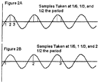
- This voltage square wave produces through the inductance/capacitor network a current waveform that to the first approximation is a sinusoidal signal superimposed with a triangular signal (see Figs 2A and 2B for shape).
- the triangular signal is equal to the signal that would have been produced if the capacitors in the network were ideal and large, so its amplitude is dependent only on the inductance of the circuit.
- Another way to analyze this is that if the converter inductances and capacitances are resonating at the switching frequency then at higher order harmonics, the capacitors' impedances are much smaller than the impedance of the inductance of the circuit. These higher order harmonic currents are more heavily dependent on the inductance of the circuit.
- the square wave that is injected can be thought of two separate waveforms.
- One is the sine wave component that is affected by the inductance and capacitance of the circuit and another that is all higher order harmonics that define the original square wave that is affected by only the inductance of the circuit.
- the sine wave component starts at zero and ends at 180 degrees. But typically the converter does not run at resonance. It will run either above or below resonance depending on the designed operating zone(s). In these cases the sine wave component will have a phase shift relative to the original square wave. This phase shift can be represented by an angle or can alternatively be represented by a sine wave component plus a cosine component both in phase with the square wave. Both components are very useful to use.
- the sine wave portion is proportional to power delivered to the secondary.
- the cosine component is the reactive component which is an indicator for the amount below or above resonance.
- the triangular component is highly dependent on the inductance of the circuit it is useful to be able to analyze if the inductance of the system is within the operating parameters. In this way, a wireless charger can determine that the secondary is too far away to even start to produce power.
- the triangular component is composed at least of the fundamental and the 3 rd harmonic component. Since the sine and cosine also contain the fundamental we must have a method to eliminate the 3 rd harmonic from those readings. Once we know how much 3 rd harmonic component there is we can subtract out the triangular portion from the original reading. Using Nyquist theory, in order to identify the 3 rd harmonic component we must make 6 samples during one period. This is accomplished by taking 3 samples during one half the period of the conduction of one of the switches. The assumption is that the other half is identical just opposite polarity. The optimum times to take the samples was discovered in the first embodiment to be at 1/6, 2/6, 3/6 of the period.
- the samples could be taken in a single period or if the ADC is not fast enough one sample can be taken one at a time just the position of the next sample can be rotated. For example, lets say that period is 1 unit long, then sample 1 is taken at 1/6, sample 2 at 1 1/3, and sample 3 taken at 2 1 ⁇ 2.(see figure 2a and 2b ). If the ADC is even slower then more periods can be placed between samples. As long as the frequency is not changing between samples the data should not be affected.
- Figure 3 is a current waveform of a LLC converter with extracted samples and values at the indicated times.
- Figure 4 shows the calculated values for the components.
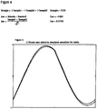
- figure 5 shows the reconstructed current waveform using these components in comparison to the original waveform.
Landscapes
- Engineering & Computer Science (AREA)
- Power Engineering (AREA)
- Computer Networks & Wireless Communication (AREA)
- Physics & Mathematics (AREA)
- General Physics & Mathematics (AREA)
- Charge And Discharge Circuits For Batteries Or The Like (AREA)
- Dc-Dc Converters (AREA)
- Ac-Ac Conversion (AREA)
Description
- Resonant converters have grown in popularity in recent years, including the use of the popular LLC converter. Resonant converters have operating conditions that can produce zero voltage switching in the switches in the primary but in other conditions might produce incorrect current wave shapes that could stress and potentially damage the switches. In other conditions the operating frequency might be safe for the switches but it could have a reverse loop gain compared to the normal zones. This occurs when going past resonance in either direction.
- Recently, inductive chargers (wireless converters) use resonant structures to process power due to the large leakage inductance. This leakage inductance changes with distance and alignment which produces a need to change the safe operating zone of the converter. Analysis of the current waveform has become more important for these types of converters.
- What is presented in this application is an innovative analysis method according to
claim 1 applied to the current waveform that will extract the needed information to keep the converter in the correct switching conditions. Claim 4 is directed at a resonant converter configured to carry out the method according toclaim 1. - The principles of the present invention are described further below with reference to the accompanying drawings.
- Traditionally the safe operating zone of a resonant converter is calculated and limits are placed on the operating frequency of the converter. Since the leakage inductance was a known and designed quantity this method has proven to be reliable. Load changes can change the safe operating zones and typically over limiting the frequency can prevent the converter from crossing over to unsafe operating zones. This comes with a penalty of restricting the converter to a narrower operating range which can impact efficiency.
- In wireless converters this problem is further increased by having the leakage inductance as a variable parameter. The leakage inductance of a wireless power system is dependent on alignment and gap distance. This variation of inductance can be a major problem in finding the safe operating zone.
- It is the purpose of this invention to introduce a new method to analyze the primary current waveform to determine whether the converter is nearing an unsafe zone and in addition determine the reactive and resistive current. By analyzing the current, according to the present invention, the correct frequency range can be determined dynamically.
- The Attached Drawings,
Figs 1-5 are described below in the context of this invention - The typical resonant converter is comprised of a half bridge configuration with tuned capacitors in the primary to resonate with a parasitic or designed leakage inductance in the primary (
fig 1 ). The secondary may also have tuned capacitors. A square wave voltage is applied to the structure by switching the switches at operating frequency with an ideal 50% duty cycle. - This voltage square wave produces through the inductance/capacitor network a current waveform that to the first approximation is a sinusoidal signal superimposed with a triangular signal (see
Figs 2A and 2B for shape). The triangular signal is equal to the signal that would have been produced if the capacitors in the network were ideal and large, so its amplitude is dependent only on the inductance of the circuit. Another way to analyze this is that if the converter inductances and capacitances are resonating at the switching frequency then at higher order harmonics, the capacitors' impedances are much smaller than the impedance of the inductance of the circuit. These higher order harmonic currents are more heavily dependent on the inductance of the circuit. Therefore, the square wave that is injected can be thought of two separate waveforms. One is the sine wave component that is affected by the inductance and capacitance of the circuit and another that is all higher order harmonics that define the original square wave that is affected by only the inductance of the circuit. - At resonance the sine wave component starts at zero and ends at 180 degrees. But typically the converter does not run at resonance. It will run either above or below resonance depending on the designed operating zone(s). In these cases the sine wave component will have a phase shift relative to the original square wave. This phase shift can be represented by an angle or can alternatively be represented by a sine wave component plus a cosine component both in phase with the square wave. Both components are very useful to use. The sine wave portion is proportional to power delivered to the secondary. The cosine component is the reactive component which is an indicator for the amount below or above resonance.
- Since the triangular component is highly dependent on the inductance of the circuit it is useful to be able to analyze if the inductance of the system is within the operating parameters. In this way, a wireless charger can determine that the secondary is too far away to even start to produce power.
- Since it advantageous to have all three components to analyze the current wave shape (sine, cosine, and triangular components), a method is needed that will extract these components. By Fourier analysis, the triangular component is composed at least of the fundamental and the 3rd harmonic component. Since the sine and cosine also contain the fundamental we must have a method to eliminate the 3rd harmonic from those readings. Once we know how much 3rd harmonic component there is we can subtract out the triangular portion from the original reading. Using Nyquist theory, in order to identify the 3rd harmonic component we must make 6 samples during one period. This is accomplished by taking 3 samples during one half the period of the conduction of one of the switches. The assumption is that the other half is identical just opposite polarity. The optimum times to take the samples was discovered in the first embodiment to be at 1/6, 2/6, 3/6 of the period.
- The samples could be taken in a single period or if the ADC is not fast enough one sample can be taken one at a time just the position of the next sample can be rotated. For example, lets say that period is 1 unit long, then
sample 1 is taken at 1/6,sample 2 at 1 1/3, andsample 3 taken at 2 ½.(seefigure 2a and 2b ). If the ADC is even slower then more periods can be placed between samples. As long as the frequency is not changing between samples the data should not be affected. - Once the 3 samples are taken the components were extracted by using the following ratios:
- Itriangle = 3*Sample1 - 3*Sample2 + 3*Sample3, where Itriangle is peak of the triangular current.
- Icos = 3*Sample1 - 3*Sample2 + 2*Sample3, where Icos is amplitude of the cosine component.
- Isin = Sample1/sqrt(3)+Sample2/sqrt(3), where Isin is the amplitude of the sine component.
- These ratios can be changed depending on the sample positions or delays.
-
Figure 3 is a current waveform of a LLC converter with extracted samples and values at the indicated times.Figure 4 shows the calculated values for the components. And figure 5 shows the reconstructed current waveform using these components in comparison to the original waveform.
Claims (5)
- A method of analyzing a primary current waveform of a resonant converter for the purpose of extracting information to keep the converter in correct switching conditions, characterized by the steps of
producing the primary current waveform by applying a square wave voltage at operating frequency with an ideal 50% duty cycle to a primary side of the converter,
approximating the primary current waveform by a sine component and a cosine component both in phase with the square wave voltage and representing a phase shift relative to the original square wave voltage and a superimposed triangular component which is dependent on the inductance of the circuit,
sampling the primary current waveform three times in half a period or sampling the primary current waveform at three different positions in a sequence of different periods,
wherein samples are taken at 1/6 (Sample1), 2/6 Sample2 and 3/6 (Sample3) of a period, and extracting information about the sine component, the cosine component and the triangular component to
 using the information about the cosine component as an indicator for an amount below or above resonance of the resonant converter and/or using the information about the sine component as an indicator for an amount of power delivered to a secondary of the resonant converter since said sine component is proportional to the power delivered to a secondary of the resonant converter and/or using the information about the triangular component to analyze whether the inductance of the resonant converter is within the operating parameters.
- The method of claim 1, wherein the resonant converter is used in a wireless inductive charging system and the extracted information about the triangular component is used to provide an indication of alignment of a primary and a secondary of the resonant converter in the wireless inductive charging system.
- The method according to claim 1, wherein the resonant converter is used in a wireless inductive charging system and the method further includes the step of using the information about the triangular component to determine whether a secondary of the resonant converter is too far away to start to produce power.
- Resonant converter comprising a half bridge configuration with tuned capacitors in a primary to resonate with a parasitic or designed leakage inductance in the primary and means adapted to perform the method according to any of claims 1 to 3.
- Wireless charging system including a resonant converter according to claim 4.
Applications Claiming Priority (1)
| Application Number | Priority Date | Filing Date | Title |
|---|---|---|---|
| US201261642816P | 2012-05-04 | 2012-05-04 |
Publications (4)
| Publication Number | Publication Date |
|---|---|
| EP2660963A2 EP2660963A2 (en) | 2013-11-06 |
| EP2660963A3 EP2660963A3 (en) | 2014-07-23 |
| EP2660963B1 true EP2660963B1 (en) | 2020-01-15 |
| EP2660963B8 EP2660963B8 (en) | 2020-03-18 |
Family
ID=48537920
Family Applications (1)
| Application Number | Title | Priority Date | Filing Date |
|---|---|---|---|
| EP13405055.8A Active EP2660963B8 (en) | 2012-05-04 | 2013-05-06 | Intelligent current analysis for resonant converters |
Country Status (2)
| Country | Link |
|---|---|
| US (1) | US9494631B2 (en) |
| EP (1) | EP2660963B8 (en) |
Families Citing this family (3)
| Publication number | Priority date | Publication date | Assignee | Title |
|---|---|---|---|---|
| US12626851B2 (en) | 2021-07-04 | 2026-05-12 | The Research Foundation For The State University Of New York | High frequency integrated planar magnetics for a bidirectional AC to DC CLLC resonant converter |
| CN115963336B (en) * | 2021-10-13 | 2025-10-17 | 北京小米移动软件有限公司 | Wireless charging test method, device, system and storage medium |
| DE102024131922A1 (en) | 2024-10-31 | 2026-04-30 | Preh Gmbh | Resonant converter, on-board charger and method for operating a resonant converter |
Family Cites Families (30)
| Publication number | Priority date | Publication date | Assignee | Title |
|---|---|---|---|---|
| US1876451A (en) | 1932-09-06 | r gurtler | ||
| FR2448722A1 (en) | 1979-02-09 | 1980-09-05 | Enertec | METHODS AND APPARATUSES FOR PERIODIC WAVEFORM ANALYSIS |
| EP0507360B1 (en) | 1991-01-30 | 1996-05-08 | The Boeing Company | Current mode bus coupler with planar coils and shields |
| EP0788211B1 (en) * | 1996-01-30 | 2002-08-28 | Sumitomo Wiring Systems, Ltd. | A connection system and a connection method |
| US6273022B1 (en) | 1998-03-14 | 2001-08-14 | Applied Materials, Inc. | Distributed inductively-coupled plasma source |
| DE19856937A1 (en) | 1998-12-10 | 2000-06-21 | Juergen Meins | Arrangement for the contactless inductive transmission of energy |
| US7126450B2 (en) | 1999-06-21 | 2006-10-24 | Access Business Group International Llc | Inductively powered apparatus |
| AU6788600A (en) | 1999-08-27 | 2001-03-26 | Illumagraphics, Llc | Induction electroluminescent lamp |
| JP2001076598A (en) | 1999-09-03 | 2001-03-23 | Omron Corp | Detection coil and proximity switch using this detection coil |
| WO2002065493A1 (en) | 2001-02-14 | 2002-08-22 | Fdk Corporation | Noncontact coupler |
| DE10112892B4 (en) | 2001-03-15 | 2007-12-13 | Paul Vahle Gmbh & Co. Kg | Device for transmitting data within a system for non-contact inductive energy transmission |
| GB0210886D0 (en) | 2002-05-13 | 2002-06-19 | Zap Wireless Technologies Ltd | Improvements relating to contact-less power transfer |
| JP4778432B2 (en) | 2003-05-23 | 2011-09-21 | オークランド ユニサービシズ リミテッド | Frequency controlled resonant converter |
| US7502237B2 (en) * | 2007-03-07 | 2009-03-10 | Eaton Corporation | Power waveform harmonic analysis using summed samples |
| CA2687060C (en) | 2007-05-10 | 2019-01-22 | Auckland Uniservices Limited | Multi power sourced electric vehicle |
| JP5118394B2 (en) | 2007-06-20 | 2013-01-16 | パナソニック株式会社 | Non-contact power transmission equipment |
| JP4743173B2 (en) * | 2007-06-29 | 2011-08-10 | セイコーエプソン株式会社 | Power transmission control device, power transmission device, non-contact power transmission system, and electronic device |
| JP4453741B2 (en) | 2007-10-25 | 2010-04-21 | トヨタ自動車株式会社 | Electric vehicle and vehicle power supply device |
| JP5363719B2 (en) | 2007-11-12 | 2013-12-11 | リコーエレメックス株式会社 | Non-contact transmission device and core |
| US8855554B2 (en) | 2008-03-05 | 2014-10-07 | Qualcomm Incorporated | Packaging and details of a wireless power device |
| GB2458476A (en) | 2008-03-19 | 2009-09-23 | Rolls Royce Plc | Inductive electrical coupler for submerged power generation apparatus |
| US8772973B2 (en) | 2008-09-27 | 2014-07-08 | Witricity Corporation | Integrated resonator-shield structures |
| US8643326B2 (en) * | 2008-09-27 | 2014-02-04 | Witricity Corporation | Tunable wireless energy transfer systems |
| KR101794901B1 (en) | 2009-02-05 | 2017-11-07 | 오클랜드 유니서비시즈 리미티드 | Inductive power transfer apparatus |
| US9283858B2 (en) | 2009-02-05 | 2016-03-15 | Auckland Uniservices Ltd | Inductive power transfer apparatus |
| JP2011142177A (en) | 2010-01-06 | 2011-07-21 | Kobe Steel Ltd | Contactless power transmission device, and coil unit for contactless power transmission device |
| JP5841132B2 (en) | 2010-05-28 | 2016-01-13 | コーニンクレッカ フィリップス エヌ ヴェKoninklijke Philips N.V. | Transmitter module used in modular power transmission system |
| KR101134625B1 (en) | 2010-07-16 | 2012-04-09 | 주식회사 한림포스텍 | Core assembly for wireless power transmission, power supplying apparatus for wireless power transmission having the same, and method for manufacturing core assembly for wireless power transmission |
| WO2012018268A1 (en) | 2010-08-05 | 2012-02-09 | Auckland Uniservices Limited | Inductive power transfer apparatus |
| BR112013023212A2 (en) * | 2011-03-11 | 2017-01-03 | Univ Utah State | METHOD AND APPARATUS FOR CONTROLLING LCL CONVERTERS USING ASYMMETRIC VOLTAGE CANCELLATION TECHNIQUES |
-
2013
- 2013-05-05 US US13/887,352 patent/US9494631B2/en active Active
- 2013-05-06 EP EP13405055.8A patent/EP2660963B8/en active Active
Non-Patent Citations (1)
| Title |
|---|
| MORADEWICZ A ET AL: "Novel FPGA Based Control of Series Resonant Converter for Contactless Power Supply", EUROCON, 2007. THE INTERNATIONAL CONFERENCE ON COMPUTER AS A TO OL, IEEE, PI, 9 September 2007 (2007-09-09), pages 1328 - 1335, XP031222982, ISBN: 978-1-4244-0812-2 * |
Also Published As
| Publication number | Publication date |
|---|---|
| US20130307559A1 (en) | 2013-11-21 |
| US9494631B2 (en) | 2016-11-15 |
| EP2660963A2 (en) | 2013-11-06 |
| EP2660963B8 (en) | 2020-03-18 |
| EP2660963A3 (en) | 2014-07-23 |
Similar Documents
| Publication | Publication Date | Title |
|---|---|---|
| EP3006947B1 (en) | Leakage current calculation device and method for calculating leakage current | |
| US9482702B2 (en) | Detection apparatus, power receiving apparatus, non-contact power transmission system and detection method | |
| Ghanem et al. | Grid impedance estimation for islanding detection and adaptive control of converters | |
| Chen et al. | Control-oriented modeling of wireless power transfer systems with phase-shift control | |
| US9548674B2 (en) | Electric power receiving device and method of receiving electric power | |
| CN104020351B (en) | A kind of be applicable to APF fractional harmonic wave detection method under laod unbalance system | |
| MXPA05009828A (en) | System and method for exact compensation of fundamental phasors. | |
| CN101587146A (en) | Parameter detection method for harmonic wave and indirect harmonic wave | |
| DE102015122484A1 (en) | System and method for measuring power in a power factor converter | |
| CN103675445B (en) | Method for high-voltage harmonic measurement through capacitive voltage mutual inductor | |
| CN104267258B (en) | A Calculation Method of Harmonic Instantaneous Power Using Incomplete S-Transform | |
| CN104155517B (en) | A kind of non-integer-period sampled error compensating method of digitalized electrical energy meter and system | |
| US9494631B2 (en) | Intelligent current analysis for resonant converters | |
| US8473232B2 (en) | Measuring apparatus | |
| US20120139359A1 (en) | Wireless charging system and transmitting end circuit thereof | |
| Hu et al. | Cycle-by-cycle average input current sensing method for LLC resonant topologies | |
| KR20190033250A (en) | Apparatus for assuring accuracy of harmonic frequency power, Method thereof, and Computer readable storage medium having the same | |
| Jiang et al. | Automatic resonant frequency tracking in unregulated LLC resonant converters based on total resonant current harmonic calculation | |
| US20190302150A1 (en) | Detection apparatus, power receiving apparatus, non-contact power transmission system and detection method | |
| CN202975173U (en) | Ground capacitance measuring instrument in transformer substation power distribution system | |
| CN111082541B (en) | Control method and device of mobile wireless power transmission system | |
| CN105629060A (en) | Grid frequency measurement method and device based on optimal baseband filtering | |
| JP2012108007A (en) | measuring device | |
| CN107870265B (en) | A kind of power-to-ground capacitance detection method based on high-precision DFT | |
| Zhang et al. | Maximum efficiency point tracking control method for series–series compensated wireless power transfer system |
Legal Events
| Date | Code | Title | Description |
|---|---|---|---|
| PUAI | Public reference made under article 153(3) epc to a published international application that has entered the european phase |
Free format text: ORIGINAL CODE: 0009012 |
|
| AK | Designated contracting states |
Kind code of ref document: A2 Designated state(s): AL AT BE BG CH CY CZ DE DK EE ES FI FR GB GR HR HU IE IS IT LI LT LU LV MC MK MT NL NO PL PT RO RS SE SI SK SM TR |
|
| AX | Request for extension of the european patent |
Extension state: BA ME |
|
| RAP1 | Party data changed (applicant data changed or rights of an application transferred) |
Owner name: DET INTERNATIONAL HOLDING LIMITED |
|
| RIN1 | Information on inventor provided before grant (corrected) |
Inventor name: DAVILA, MARCO ANTONIO |
|
| PUAL | Search report despatched |
Free format text: ORIGINAL CODE: 0009013 |
|
| AK | Designated contracting states |
Kind code of ref document: A3 Designated state(s): AL AT BE BG CH CY CZ DE DK EE ES FI FR GB GR HR HU IE IS IT LI LT LU LV MC MK MT NL NO PL PT RO RS SE SI SK SM TR |
|
| AX | Request for extension of the european patent |
Extension state: BA ME |
|
| 17P | Request for examination filed |
Effective date: 20150123 |
|
| RBV | Designated contracting states (corrected) |
Designated state(s): AL AT BE BG CH CY CZ DE DK EE ES FI FR GB GR HR HU IE IS IT LI LT LU LV MC MK MT NL NO PL PT RO RS SE SI SK SM TR |
|
| STAA | Information on the status of an ep patent application or granted ep patent |
Free format text: STATUS: EXAMINATION IS IN PROGRESS |
|
| 17Q | First examination report despatched |
Effective date: 20161024 |
|
| RAP1 | Party data changed (applicant data changed or rights of an application transferred) |
Owner name: DELTA ELECTRONICS (THAILAND) PUBLIC CO., LTD. |
|
| RIC1 | Information provided on ipc code assigned before grant |
Ipc: H02M 3/338 20060101AFI20190705BHEP Ipc: H02J 50/90 20160101ALN20190705BHEP Ipc: H02J 7/02 20160101ALN20190705BHEP |
|
| GRAP | Despatch of communication of intention to grant a patent |
Free format text: ORIGINAL CODE: EPIDOSNIGR1 |
|
| STAA | Information on the status of an ep patent application or granted ep patent |
Free format text: STATUS: GRANT OF PATENT IS INTENDED |
|
| RIC1 | Information provided on ipc code assigned before grant |
Ipc: H02J 50/90 20160101ALN20190729BHEP Ipc: H02J 50/12 20160101ALN20190729BHEP Ipc: G01R 27/26 20060101ALN20190729BHEP Ipc: H02M 3/338 20060101AFI20190729BHEP Ipc: H02J 7/02 20160101ALN20190729BHEP |
|
| INTG | Intention to grant announced |
Effective date: 20190826 |
|
| GRAS | Grant fee paid |
Free format text: ORIGINAL CODE: EPIDOSNIGR3 |
|
| GRAA | (expected) grant |
Free format text: ORIGINAL CODE: 0009210 |
|
| STAA | Information on the status of an ep patent application or granted ep patent |
Free format text: STATUS: THE PATENT HAS BEEN GRANTED |
|
| AK | Designated contracting states |
Kind code of ref document: B1 Designated state(s): AL AT BE BG CH CY CZ DE DK EE ES FI FR GB GR HR HU IE IS IT LI LT LU LV MC MK MT NL NO PL PT RO RS SE SI SK SM TR |
|
| REG | Reference to a national code |
Ref country code: CH Ref legal event code: EP Ref country code: GB Ref legal event code: FG4D |
|
| REG | Reference to a national code |
Ref country code: IE Ref legal event code: FG4D |
|
| REG | Reference to a national code |
Ref country code: AT Ref legal event code: REF Ref document number: 1226043 Country of ref document: AT Kind code of ref document: T Effective date: 20200215 |
|
| REG | Reference to a national code |
Ref country code: DE Ref legal event code: R096 Ref document number: 602013065079 Country of ref document: DE |
|
| REG | Reference to a national code |
Ref country code: CH Ref legal event code: PK Free format text: BERICHTIGUNG B8 |
|
| REG | Reference to a national code |
Ref country code: SE Ref legal event code: TRGR |
|
| REG | Reference to a national code |
Ref country code: NL Ref legal event code: MP Effective date: 20200115 |
|
| REG | Reference to a national code |
Ref country code: LT Ref legal event code: MG4D |
|
| PG25 | Lapsed in a contracting state [announced via postgrant information from national office to epo] |
Ref country code: NO Free format text: LAPSE BECAUSE OF FAILURE TO SUBMIT A TRANSLATION OF THE DESCRIPTION OR TO PAY THE FEE WITHIN THE PRESCRIBED TIME-LIMIT Effective date: 20200415 Ref country code: RS Free format text: LAPSE BECAUSE OF FAILURE TO SUBMIT A TRANSLATION OF THE DESCRIPTION OR TO PAY THE FEE WITHIN THE PRESCRIBED TIME-LIMIT Effective date: 20200115 Ref country code: NL Free format text: LAPSE BECAUSE OF FAILURE TO SUBMIT A TRANSLATION OF THE DESCRIPTION OR TO PAY THE FEE WITHIN THE PRESCRIBED TIME-LIMIT Effective date: 20200115 Ref country code: FI Free format text: LAPSE BECAUSE OF FAILURE TO SUBMIT A TRANSLATION OF THE DESCRIPTION OR TO PAY THE FEE WITHIN THE PRESCRIBED TIME-LIMIT Effective date: 20200115 Ref country code: PT Free format text: LAPSE BECAUSE OF FAILURE TO SUBMIT A TRANSLATION OF THE DESCRIPTION OR TO PAY THE FEE WITHIN THE PRESCRIBED TIME-LIMIT Effective date: 20200607 |
|
| PG25 | Lapsed in a contracting state [announced via postgrant information from national office to epo] |
Ref country code: IS Free format text: LAPSE BECAUSE OF FAILURE TO SUBMIT A TRANSLATION OF THE DESCRIPTION OR TO PAY THE FEE WITHIN THE PRESCRIBED TIME-LIMIT Effective date: 20200515 Ref country code: GR Free format text: LAPSE BECAUSE OF FAILURE TO SUBMIT A TRANSLATION OF THE DESCRIPTION OR TO PAY THE FEE WITHIN THE PRESCRIBED TIME-LIMIT Effective date: 20200416 Ref country code: HR Free format text: LAPSE BECAUSE OF FAILURE TO SUBMIT A TRANSLATION OF THE DESCRIPTION OR TO PAY THE FEE WITHIN THE PRESCRIBED TIME-LIMIT Effective date: 20200115 Ref country code: LV Free format text: LAPSE BECAUSE OF FAILURE TO SUBMIT A TRANSLATION OF THE DESCRIPTION OR TO PAY THE FEE WITHIN THE PRESCRIBED TIME-LIMIT Effective date: 20200115 Ref country code: BG Free format text: LAPSE BECAUSE OF FAILURE TO SUBMIT A TRANSLATION OF THE DESCRIPTION OR TO PAY THE FEE WITHIN THE PRESCRIBED TIME-LIMIT Effective date: 20200415 |
|
| REG | Reference to a national code |
Ref country code: CH Ref legal event code: PFA Owner name: DELTA ELECTRONICS (THAILAND) PUBLIC CO., LTD., TH Free format text: FORMER OWNER: DELTA ELECTRONICS (THAILAND) PUBLIC CO., LTD., TH |
|
| REG | Reference to a national code |
Ref country code: DE Ref legal event code: R097 Ref document number: 602013065079 Country of ref document: DE |
|
| PG25 | Lapsed in a contracting state [announced via postgrant information from national office to epo] |
Ref country code: DK Free format text: LAPSE BECAUSE OF FAILURE TO SUBMIT A TRANSLATION OF THE DESCRIPTION OR TO PAY THE FEE WITHIN THE PRESCRIBED TIME-LIMIT Effective date: 20200115 Ref country code: EE Free format text: LAPSE BECAUSE OF FAILURE TO SUBMIT A TRANSLATION OF THE DESCRIPTION OR TO PAY THE FEE WITHIN THE PRESCRIBED TIME-LIMIT Effective date: 20200115 Ref country code: ES Free format text: LAPSE BECAUSE OF FAILURE TO SUBMIT A TRANSLATION OF THE DESCRIPTION OR TO PAY THE FEE WITHIN THE PRESCRIBED TIME-LIMIT Effective date: 20200115 Ref country code: LT Free format text: LAPSE BECAUSE OF FAILURE TO SUBMIT A TRANSLATION OF THE DESCRIPTION OR TO PAY THE FEE WITHIN THE PRESCRIBED TIME-LIMIT Effective date: 20200115 Ref country code: CZ Free format text: LAPSE BECAUSE OF FAILURE TO SUBMIT A TRANSLATION OF THE DESCRIPTION OR TO PAY THE FEE WITHIN THE PRESCRIBED TIME-LIMIT Effective date: 20200115 Ref country code: RO Free format text: LAPSE BECAUSE OF FAILURE TO SUBMIT A TRANSLATION OF THE DESCRIPTION OR TO PAY THE FEE WITHIN THE PRESCRIBED TIME-LIMIT Effective date: 20200115 Ref country code: SK Free format text: LAPSE BECAUSE OF FAILURE TO SUBMIT A TRANSLATION OF THE DESCRIPTION OR TO PAY THE FEE WITHIN THE PRESCRIBED TIME-LIMIT Effective date: 20200115 Ref country code: SM Free format text: LAPSE BECAUSE OF FAILURE TO SUBMIT A TRANSLATION OF THE DESCRIPTION OR TO PAY THE FEE WITHIN THE PRESCRIBED TIME-LIMIT Effective date: 20200115 |
|
| REG | Reference to a national code |
Ref country code: AT Ref legal event code: MK05 Ref document number: 1226043 Country of ref document: AT Kind code of ref document: T Effective date: 20200115 |
|
| PLBE | No opposition filed within time limit |
Free format text: ORIGINAL CODE: 0009261 |
|
| STAA | Information on the status of an ep patent application or granted ep patent |
Free format text: STATUS: NO OPPOSITION FILED WITHIN TIME LIMIT |
|
| 26N | No opposition filed |
Effective date: 20201016 |
|
| PG25 | Lapsed in a contracting state [announced via postgrant information from national office to epo] |
Ref country code: AT Free format text: LAPSE BECAUSE OF FAILURE TO SUBMIT A TRANSLATION OF THE DESCRIPTION OR TO PAY THE FEE WITHIN THE PRESCRIBED TIME-LIMIT Effective date: 20200115 Ref country code: MC Free format text: LAPSE BECAUSE OF FAILURE TO SUBMIT A TRANSLATION OF THE DESCRIPTION OR TO PAY THE FEE WITHIN THE PRESCRIBED TIME-LIMIT Effective date: 20200115 |
|
| PG25 | Lapsed in a contracting state [announced via postgrant information from national office to epo] |
Ref country code: PL Free format text: LAPSE BECAUSE OF FAILURE TO SUBMIT A TRANSLATION OF THE DESCRIPTION OR TO PAY THE FEE WITHIN THE PRESCRIBED TIME-LIMIT Effective date: 20200115 Ref country code: SI Free format text: LAPSE BECAUSE OF FAILURE TO SUBMIT A TRANSLATION OF THE DESCRIPTION OR TO PAY THE FEE WITHIN THE PRESCRIBED TIME-LIMIT Effective date: 20200115 |
|
| REG | Reference to a national code |
Ref country code: BE Ref legal event code: MM Effective date: 20200531 |
|
| PG25 | Lapsed in a contracting state [announced via postgrant information from national office to epo] |
Ref country code: LU Free format text: LAPSE BECAUSE OF NON-PAYMENT OF DUE FEES Effective date: 20200506 |
|
| PG25 | Lapsed in a contracting state [announced via postgrant information from national office to epo] |
Ref country code: IE Free format text: LAPSE BECAUSE OF NON-PAYMENT OF DUE FEES Effective date: 20200506 |
|
| PG25 | Lapsed in a contracting state [announced via postgrant information from national office to epo] |
Ref country code: BE Free format text: LAPSE BECAUSE OF NON-PAYMENT OF DUE FEES Effective date: 20200531 |
|
| PG25 | Lapsed in a contracting state [announced via postgrant information from national office to epo] |
Ref country code: TR Free format text: LAPSE BECAUSE OF FAILURE TO SUBMIT A TRANSLATION OF THE DESCRIPTION OR TO PAY THE FEE WITHIN THE PRESCRIBED TIME-LIMIT Effective date: 20200115 Ref country code: MT Free format text: LAPSE BECAUSE OF FAILURE TO SUBMIT A TRANSLATION OF THE DESCRIPTION OR TO PAY THE FEE WITHIN THE PRESCRIBED TIME-LIMIT Effective date: 20200115 Ref country code: CY Free format text: LAPSE BECAUSE OF FAILURE TO SUBMIT A TRANSLATION OF THE DESCRIPTION OR TO PAY THE FEE WITHIN THE PRESCRIBED TIME-LIMIT Effective date: 20200115 |
|
| PG25 | Lapsed in a contracting state [announced via postgrant information from national office to epo] |
Ref country code: MK Free format text: LAPSE BECAUSE OF FAILURE TO SUBMIT A TRANSLATION OF THE DESCRIPTION OR TO PAY THE FEE WITHIN THE PRESCRIBED TIME-LIMIT Effective date: 20200115 Ref country code: AL Free format text: LAPSE BECAUSE OF FAILURE TO SUBMIT A TRANSLATION OF THE DESCRIPTION OR TO PAY THE FEE WITHIN THE PRESCRIBED TIME-LIMIT Effective date: 20200115 |
|
| PGFP | Annual fee paid to national office [announced via postgrant information from national office to epo] |
Ref country code: DE Payment date: 20250521 Year of fee payment: 13 |
|
| PGFP | Annual fee paid to national office [announced via postgrant information from national office to epo] |
Ref country code: GB Payment date: 20250521 Year of fee payment: 13 |
|
| PGFP | Annual fee paid to national office [announced via postgrant information from national office to epo] |
Ref country code: IT Payment date: 20250521 Year of fee payment: 13 |
|
| PGFP | Annual fee paid to national office [announced via postgrant information from national office to epo] |
Ref country code: FR Payment date: 20250528 Year of fee payment: 13 |
|
| PGFP | Annual fee paid to national office [announced via postgrant information from national office to epo] |
Ref country code: CH Payment date: 20250601 Year of fee payment: 13 |
|
| PGFP | Annual fee paid to national office [announced via postgrant information from national office to epo] |
Ref country code: SE Payment date: 20250521 Year of fee payment: 13 |