EP2660115A2 - Speed control device and program for speed control device - Google Patents
Speed control device and program for speed control device Download PDFInfo
- Publication number
- EP2660115A2 EP2660115A2 EP13002281.7A EP13002281A EP2660115A2 EP 2660115 A2 EP2660115 A2 EP 2660115A2 EP 13002281 A EP13002281 A EP 13002281A EP 2660115 A2 EP2660115 A2 EP 2660115A2
- Authority
- EP
- European Patent Office
- Prior art keywords
- vehicle speed
- accelerator
- demand
- acceleration
- feedback control
- Prior art date
- Legal status (The legal status is an assumption and is not a legal conclusion. Google has not performed a legal analysis and makes no representation as to the accuracy of the status listed.)
- Withdrawn
Links
Images


Classifications
-
- G—PHYSICS
- G06—COMPUTING OR CALCULATING; COUNTING
- G06F—ELECTRIC DIGITAL DATA PROCESSING
- G06F17/00—Digital computing or data processing equipment or methods, specially adapted for specific functions
-
- B—PERFORMING OPERATIONS; TRANSPORTING
- B60—VEHICLES IN GENERAL
- B60W—CONJOINT CONTROL OF VEHICLE SUB-UNITS OF DIFFERENT TYPE OR DIFFERENT FUNCTION; CONTROL SYSTEMS SPECIALLY ADAPTED FOR HYBRID VEHICLES; ROAD VEHICLE DRIVE CONTROL SYSTEMS FOR PURPOSES NOT RELATED TO THE CONTROL OF A PARTICULAR SUB-UNIT
- B60W50/00—Details of control systems for road vehicle drive control not related to the control of a particular sub-unit, e.g. process diagnostic or vehicle driver interfaces
- B60W50/0097—Predicting future conditions
-
- B—PERFORMING OPERATIONS; TRANSPORTING
- B60—VEHICLES IN GENERAL
- B60W—CONJOINT CONTROL OF VEHICLE SUB-UNITS OF DIFFERENT TYPE OR DIFFERENT FUNCTION; CONTROL SYSTEMS SPECIALLY ADAPTED FOR HYBRID VEHICLES; ROAD VEHICLE DRIVE CONTROL SYSTEMS FOR PURPOSES NOT RELATED TO THE CONTROL OF A PARTICULAR SUB-UNIT
- B60W10/00—Conjoint control of vehicle sub-units of different type or different function
- B60W10/04—Conjoint control of vehicle sub-units of different type or different function including control of propulsion units
- B60W10/06—Conjoint control of vehicle sub-units of different type or different function including control of propulsion units including control of combustion engines
-
- B—PERFORMING OPERATIONS; TRANSPORTING
- B60—VEHICLES IN GENERAL
- B60W—CONJOINT CONTROL OF VEHICLE SUB-UNITS OF DIFFERENT TYPE OR DIFFERENT FUNCTION; CONTROL SYSTEMS SPECIALLY ADAPTED FOR HYBRID VEHICLES; ROAD VEHICLE DRIVE CONTROL SYSTEMS FOR PURPOSES NOT RELATED TO THE CONTROL OF A PARTICULAR SUB-UNIT
- B60W10/00—Conjoint control of vehicle sub-units of different type or different function
- B60W10/18—Conjoint control of vehicle sub-units of different type or different function including control of braking systems
- B60W10/184—Conjoint control of vehicle sub-units of different type or different function including control of braking systems with wheel brakes
-
- B—PERFORMING OPERATIONS; TRANSPORTING
- B60—VEHICLES IN GENERAL
- B60W—CONJOINT CONTROL OF VEHICLE SUB-UNITS OF DIFFERENT TYPE OR DIFFERENT FUNCTION; CONTROL SYSTEMS SPECIALLY ADAPTED FOR HYBRID VEHICLES; ROAD VEHICLE DRIVE CONTROL SYSTEMS FOR PURPOSES NOT RELATED TO THE CONTROL OF A PARTICULAR SUB-UNIT
- B60W30/00—Purposes of road vehicle drive control systems not related to the control of a particular sub-unit, e.g. of systems using conjoint control of vehicle sub-units
- B60W30/14—Adaptive cruise control
- B60W30/143—Speed control
-
- B—PERFORMING OPERATIONS; TRANSPORTING
- B60—VEHICLES IN GENERAL
- B60W—CONJOINT CONTROL OF VEHICLE SUB-UNITS OF DIFFERENT TYPE OR DIFFERENT FUNCTION; CONTROL SYSTEMS SPECIALLY ADAPTED FOR HYBRID VEHICLES; ROAD VEHICLE DRIVE CONTROL SYSTEMS FOR PURPOSES NOT RELATED TO THE CONTROL OF A PARTICULAR SUB-UNIT
- B60W50/00—Details of control systems for road vehicle drive control not related to the control of a particular sub-unit, e.g. process diagnostic or vehicle driver interfaces
- B60W50/06—Improving the dynamic response of the control system, e.g. improving the speed of regulation or avoiding hunting or overshoot
-
- B—PERFORMING OPERATIONS; TRANSPORTING
- B60—VEHICLES IN GENERAL
- B60W—CONJOINT CONTROL OF VEHICLE SUB-UNITS OF DIFFERENT TYPE OR DIFFERENT FUNCTION; CONTROL SYSTEMS SPECIALLY ADAPTED FOR HYBRID VEHICLES; ROAD VEHICLE DRIVE CONTROL SYSTEMS FOR PURPOSES NOT RELATED TO THE CONTROL OF A PARTICULAR SUB-UNIT
- B60W50/00—Details of control systems for road vehicle drive control not related to the control of a particular sub-unit, e.g. process diagnostic or vehicle driver interfaces
- B60W50/08—Interaction between the driver and the control system
- B60W50/10—Interpretation of driver requests or demands
-
- B—PERFORMING OPERATIONS; TRANSPORTING
- B60—VEHICLES IN GENERAL
- B60W—CONJOINT CONTROL OF VEHICLE SUB-UNITS OF DIFFERENT TYPE OR DIFFERENT FUNCTION; CONTROL SYSTEMS SPECIALLY ADAPTED FOR HYBRID VEHICLES; ROAD VEHICLE DRIVE CONTROL SYSTEMS FOR PURPOSES NOT RELATED TO THE CONTROL OF A PARTICULAR SUB-UNIT
- B60W2540/00—Input parameters relating to occupants
- B60W2540/10—Accelerator pedal position
-
- B—PERFORMING OPERATIONS; TRANSPORTING
- B60—VEHICLES IN GENERAL
- B60W—CONJOINT CONTROL OF VEHICLE SUB-UNITS OF DIFFERENT TYPE OR DIFFERENT FUNCTION; CONTROL SYSTEMS SPECIALLY ADAPTED FOR HYBRID VEHICLES; ROAD VEHICLE DRIVE CONTROL SYSTEMS FOR PURPOSES NOT RELATED TO THE CONTROL OF A PARTICULAR SUB-UNIT
- B60W2540/00—Input parameters relating to occupants
- B60W2540/12—Brake pedal position
-
- Y—GENERAL TAGGING OF NEW TECHNOLOGICAL DEVELOPMENTS; GENERAL TAGGING OF CROSS-SECTIONAL TECHNOLOGIES SPANNING OVER SEVERAL SECTIONS OF THE IPC; TECHNICAL SUBJECTS COVERED BY FORMER USPC CROSS-REFERENCE ART COLLECTIONS [XRACs] AND DIGESTS
- Y02—TECHNOLOGIES OR APPLICATIONS FOR MITIGATION OR ADAPTATION AGAINST CLIMATE CHANGE
- Y02T—CLIMATE CHANGE MITIGATION TECHNOLOGIES RELATED TO TRANSPORTATION
- Y02T10/00—Road transport of goods or passengers
- Y02T10/80—Technologies aiming to reduce greenhouse gasses emissions common to all road transportation technologies
- Y02T10/84—Data processing systems or methods, management, administration
Definitions
- the present invention generally relates to a speed control for controlling a speed of, for example, a vehicle on a chassis dynamo and, in particular, to a speed control device and a program therefor for appropriately controlling an accelerator and a brake of a vehicle so as to render an actual vehicle speed of the vehicle to follow a demand vehicle speed.
- a running pattern is determined for measuring fuel consumption, and there has been known a speed control device for controlling an accelerator and a brake of a vehicle (in particular, an automobile) so that an actual vehicle speed may follow a demand vehicle speed indicated in the running pattern.
- any of an accelerator pedal or a brake pedal of a vehicle disposed on a chassis dynamo is operated by an amount according to a deviation between an actual vehicle speed and a demand vehicle speed so as to render the actual vehicle speed to follow the demand vehicle speed.
- this speed control device since a feedback control of the accelerator or the brake is selectively performed almost like a person, it is necessary to determine switching timing of the controls.
- timing of switching from a vehicle speed feedback control by operating an accelerator to a vehicle speed feedback control by operating a brake is set to a time point when the actual vehicle speed is higher than the demand vehicle speed and the vehicle is in a situation that the actual vehicle speed has to be decelerated and when an accelerator opening degree becomes 0 (i.e., accelerator is in a fully closed position), and it is configured that the vehicle speed feedback control is switched to the vehicle speed feedback control by operating the brake at this time point.
- timing of switching from a vehicle speed feedback control by operating a brake to a vehicle speed feedback control by operating an accelerator is also similar, although reverse, to the above case. That is, the switching timing thereof is set to a time point when the actual vehicle speed is lower than the demand vehicle speed and the vehicle is in a situation that the actual vehicle speed has to be accelerated and when a brake depressing degree becomes 0 (i.e., brake is in an effective beginning position), and it is configured that the vehicle speed feedback control is switched to the vehicle speed feedback control by operating the accelerator at this time point.
- Patent Literature 1 there has been also a conceivable configuration of determining which of an accelerator or a brake should be controlled by comparing a demand horsepower and an actual horsepower.
- Patent Literature 1 JP Heisei 3-233339 A
- the present invention has been made to solve such problems and its essential object is to more accurately set a switching timing between a brake feedback control and an accelerator feedback control in a speed control device of a vehicle so as to further improve followability of an actual vehicle speed to a demand vehicle speed.
- a speed control device includes: an actual vehicle speed acquisition part for acquiring an actual vehicle speed of a vehicle; a demand vehicle speed acquisition part for acquiring a demand vehicle speed of the vehicle; and a vehicle speed control part selectively performing any one of an accelerator feedback control controlling the actual vehicle speed by driving an accelerator in accordance with a deviation between the actual vehicle speed and the demand vehicle speed or a brake feedback control controlling the actual vehicle speed by driving a brake in accordance with the deviation in order that the actual vehicle speed is allowed to follow the demand vehicle speed, wherein the speed control device further includes: an accelerator-fully-closed acceleration acquisition part for acquiring an accelerator-fully-closed acceleration which is acceleration of the vehicle in a state that the accelerator is fully closed; and a demand acceleration acquisition part for acquiring a demand acceleration of the vehicle, whereby in the case where a first condition that a first future demand acceleration which is a demand acceleration when a predetermined first time has elapsed from the present time is lower than a value obtained by subtracting a first allowable value from the
- the situations at the present time are also included in the control switching condition. Specifically, it is desirable that, in the case where a second condition that the actual vehicle speed at the present time is higher than a value obtained by adding a predetermined second allowable value to the demand vehicle speed is satisfied in addition to the first condition, the accelerator feedback control is stopped and the accelerator is directed toward the fully closed position to start the brake feedback control at the same time.
- a first expected actual vehicle speed which is an actual vehicle speed when a predetermined second time has elapsed is calculated while maintaining the actual acceleration at the present time, in the meanwhile, in the case where the first condition or a third condition that the first expected actual vehicle speed is higher than a value obtained by adding a predetermined third allowable value to a first future demand vehicle speed which is a demand vehicle speed at a time when a second time has elapsed from the present time is satisfied, the accelerator feedback control is stopped and the accelerator is directed toward the fully closed position to start the brake feedback control at the same time.
- the accelerator feedback control is stopped and the accelerator is directed toward the fully closed position to start the brake feedback control, whereby a switching timing can be more accurately determined.
- the brake feedback control is stopped and the brake is directed toward the effective beginning position to start the accelerator feedback control at the same time.
- a situation after a predetermined elapsed time is expected from vehicle speed related information at the present time to perform a pre-read control to switch between the accelerator feedback control and the brake feedback control at the present time based on the expectation after the predetermined elapsed time, and therefore the followability or quick reaction capability of an actual vehicle speed to a demand vehicle speed can be remarkably improved.
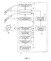
- a speed control device is adapted to control a speed of an automobile, that is, a vehicle disposed on a chassis dynamo SD.
- the speed control device includes an accelerator drive mechanism 1 for driving an accelerator and a brake drive mechanism 2 for driving a brake which are arranged in a driver's seat of an automobile and further includes a control main body 4 which outputs a control signal to be applied to the accelerator drive mechanism 1 and the brake drive mechanism 2 to thereby control an accelerator opening degree and a brake depressing degree.
- each of the accelerator drive mechanism 1 and the brake drive mechanism 3 is provided with a cylinder member and a tip end portion thereof is allowed to be advanced and retreated by expanding and contracting the cylinder member. Then, the tip end portion is rendered to abut to an accelerator pedal AP and a brake pedal BP and it is configured that the accelerator and brake are driven by advancing and retreating the tip end portion.
- each of the accelerator drive mechanism 1 and the brake drive mechanism 2 is provided with a position detecting part (such as, e.g., a rotary encoder, not shown) for detecting an advance/retreat position of the tip end portion, and it is configured that the accelerator opening degree and the brake depressing degree can be confirmed based on a position signal outputted from the position detecting part.
- a position detecting part such as, e.g., a rotary encoder, not shown
- control main body 4 is composed of, although not shown, a CPU, a memory, an A/D converter, a D/A converter, a communication interface and the like, and the CPU and peripheral equipment thereof are cooperated according to a predetermined program stored in the memory to thereby perform functions as an actual vehicle speed acquisition part 41, an actual acceleration acquisition part 42, a demand vehicle speed data storage part 43, a demand vehicle speed acquisition part 44, a demand acceleration acquisition part 45, an accelerator opening degree acquisition part 46, a brake depressing degree acquisition part 47, an accelerator-fully-closed acceleration acquisition part 49, a vehicle speed control part 48, and the like.
- the actual vehicle speed acquisition part 41 is adapted to receive a vehicle speed signal from a vehicle speed sensor 3 mounted to, e.g., the chassis dynamo SD or an automobile and convert the received value thereof to an actual vehicle speed.
- the actual acceleration acquisition part 42 is adapted to calculate an actual acceleration based on a variation with time lapse of the vehicle speed acquired by the actual vehicle speed acquisition part 41. Note that the actual acceleration may be acquired by receiving a signal from an acceleration sensor separately provided.
- the demand vehicle speed data storage part 43 is preset in a predetermined area of the memory to store data with time lapse of a demand vehicle speed, i.e., demand vehicle speed data indicative of a demand vehicle speed every time.
- the demand vehicle speed acquisition part 44 is adapted to access the demand vehicle speed data storage part 43 and acquire a demand vehicle speed at any specified time (present time, past and future).
- the demand acceleration acquisition part 45 is adapted to access the demand vehicle speed data storage part 43 and calculate a demand acceleration at any specified time (present time, past and future) from a variation in time of a demand vehicle speed at that time.
- the accelerator opening degree acquisition part 46 is adapted to receive a position signal outputted from the accelerator drive mechanism 1 and convert a value of the received position signal to an accelerator opening degree. Note that “accelerator fully closed” is synonymous with “accelerator opening degree 0”, hereinafter.
- the brake depressing degree acquisition part 47 is adapted to receive a position signal outputted from the brake drive mechanism 2 and convert a value of the received position signal to a brake depressing degree. Note that "brake-effective beginning position” is synonymous with “brake depressing degree 0", hereinafter.
- the accelerator-fully-closed acceleration acquisition part 49 is adapted to acquire an accelerator-fully-closed acceleration that is acceleration of a vehicle when the accelerator is fully closed and the brake depressing degree is 0. This acceleration corresponds to a deceleration when so-called an engine brake is acting.
- this accelerator-fully-closed acceleration is stored in an accelerator-fully-closed acceleration storage part 410 defined in a predetermined area of the memory, and a value calculated from such as performance data etc. of the vehicle is set to a first default value thereof.
- the accelerator-fully-closed acceleration stored in the accelerator-fully-closed acceleration storage part 410 is set so as to be sequentially updated by a value obtained by learning from an actual acceleration obtained by the actual acceleration acquisition part 42 through such as a running test.
- the accelerator-fully-closed acceleration is not a single value but a plurality of values may be defined therefor using parameters such as, e.g., a gear ratio and an engine rotation.
- the accelerator-fully-closed acceleration acquisition part 49 may be adapted to learn and specify the accelerator-fully-closed acceleration from the values of the parameters.
- the vehicle speed control part 48 has at least a function of selectively performing any one of an accelerator feedback control in which the accelerator is driven in accordance with a deviation between the actual vehicle speed and a demand vehicle speed so as to control the actual vehicle speed and a brake feedback control in which the brake is driven in accordance with the deviation so as to control the actual vehicle speed, in order to render the actual vehicle speed to follow the demand vehicle speed.
- an actual vehicle speed and a demand vehicle speed at the present time are acquired by the actual vehicle speed acquisition part 41 and the actual acceleration acquisition part 42, respectively, in Step S12.
- a first future demand acceleration which is a demand acceleration when a predetermined first time (herein, 0.1 second) has elapsed from the present time and the accelerator-fully-closed acceleration are acquired by the demand acceleration acquisition part 45 and the accelerator-fully-closed acceleration acquisition part 49, respectively, in Step S13.
- the vehicle speed control part 48 compares the first future demand acceleration and the fully closed acceleration and determines whether or not a first condition that the first future demand acceleration is lower than a value obtained by subtracting a predetermined first allowable value (herein, e.g., 0) from the fully closed acceleration is satisfied in Step S14.
- a predetermined first allowable value herein, e.g., 0
- the vehicle speed control part 48 determines whether or not a second condition that the actual vehicle speed at the present time is higher than a value obtained by adding a predetermined second allowable value (herein, e.g., 0.2 km/h) to the demand vehicle speed is satisfied in Step S15.
- a predetermined second allowable value herein, e.g., 0.2 km/h
- the vehicle speed control part 48 stops the accelerator feedback control and instructs the accelerator drive mechanism 1 to return the accelerator opening degree to the fully closed position at the highest drive speed and starts the brake feedback control in Step S16.
- Fig. 4 is a timing chart showing an outline of the control shown in Fig. 2 .
- an actual vehicle speed and a demand vehicle speed at the present time are acquired by the actual vehicle speed acquisition part 41 and the actual acceleration acquisition part 42, respectively, in Step S22.
- a second future demand acceleration which is a demand acceleration when a predetermined third time (herein, 0.1 second) has elapsed from the present time and the accelerator-fully-closed acceleration are acquired by the demand acceleration acquisition part 45 and the accelerator-fully-closed acceleration acquisition part 49, respectively, in Step S23.
- the vehicle speed control part 48 compares the second future demand acceleration and the fully closed acceleration and determines whether or not a fifth condition that the second future demand acceleration is higher than a value obtained by adding a predetermined fifth allowable value (herein, e.g., 0) to the fully closed acceleration is satisfied in Step S24.
- a predetermined fifth allowable value herein, e.g., 0
- the vehicle speed control part 48 determines whether or not a sixth condition that the actual vehicle speed at the present time is lower than a value obtained by subtracting a predetermined sixth allowable value (herein, e.g., 0.2 km/h) from the demand vehicle speed is satisfied in Step S25.
- a predetermined sixth allowable value herein, e.g., 0.2 km/h
- the vehicle speed control part 48 stops the brake feedback control and instructs the brake drive mechanism 2 to return the brake position to the effective beginning position at the highest drive speed and starts the accelerator feedback control in Step S26.
- Fig. 5 is a timing chart showing an outline of the control shown in Fig. 3 .
- these third and fourth conditions can supplement in such a case where a learning value of the accelerator-fully-closed acceleration is improper.
- the third condition is a condition that a first expectation actual vehicle speed after a predetermined second time has elapsed from the present time is higher than a value obtained by adding a predetermined third allowable value to the first future demand vehicle speed which is a demand speed after the same second time has elapsed from the present time.
- the first expectation actual vehicle speed is calculated from the actual vehicle speed at the present time on the premise that the actual acceleration is maintained as it is by the vehicle speed control part 48.
- the second time is set to be larger than the first time, for example, 1 second.
- the first future demand vehicle speed is acquired by the demand vehicle speed acquisition part 44.
- the fourth condition is a condition that the actual vehicle speed at the present time is higher than a value obtained by adding a predetermined fourth allowable value to the demand vehicle speed. Then, in the case where a following conditional expression T1 is true, the vehicle speed control part 48 stops the accelerator feedback control, instructs the accelerator drive mechanism 1 to return the accelerator opening degree to the fully closed position at a maximum drive speed, and starts the brake feedback control at the same time.
- T1 (Condition 1 and Condition 2) or (Condition 3 and Condition 4)
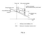
- Fig. 6 shows a timing chart for explaining the above term (Condition 3 and Condition 4).
- the seventh condition is a condition that a second expectation actual vehicle speed after a predetermined fourth time has elapsed from the present time is lower than a value obtained by subtracting a predetermined seventh allowable value from the second future demand vehicle speed which is a demand speed after the predetermined fourth time has elapsed from the present time.
- the second expectation actual vehicle speed is calculated from the actual vehicle speed at the present time on the premise that the actual acceleration is maintained as it is by the vehicle speed control part 48.
- the fourth time is set to be larger than the third time, for example, 1 second.
- the second future demand vehicle speed is acquired by the demand vehicle speed acquisition part 44.
- the eighth condition is a condition that the actual vehicle speed at the present time is lower than a value obtained by subtracting a predetermined eighth allowable value from the demand vehicle speed.
- the vehicle speed control part 48 stops the accelerator feedback control, instructs the accelerator drive mechanism 1 to return the accelerator opening degree to the fully closed position at a maximum drive speed, and starts the brake feedback control at the same time.
- T2 (Condition 5 and Condition 6) or (Condition 7 and Condition 8)
- Fig. 7 shows a timing chart for explaining the above term (Condition 7 and Condition 8).
- the present invention is not limited to the above embodiment.
- the present embodiment may be used only in the case of switching from the accelerator feedback control to the brake feedback control while the conventional speed control is performed in the reverse case.
- the present embodiment may be used only in the case of switching from the brake feedback control to the accelerator feedback control while the conventional speed control is performed in the reverse case.
- the conditions 2 to 4 and 6 to 8 are not necessarily required and only a part thereof may be used, and further another condition may be added.
- the control may be switched at that time as in the conventional method.
Landscapes
- Engineering & Computer Science (AREA)
- Transportation (AREA)
- Mechanical Engineering (AREA)
- Automation & Control Theory (AREA)
- Combustion & Propulsion (AREA)
- Chemical & Material Sciences (AREA)
- Human Computer Interaction (AREA)
- Theoretical Computer Science (AREA)
- Physics & Mathematics (AREA)
- Data Mining & Analysis (AREA)
- Mathematical Physics (AREA)
- Software Systems (AREA)
- General Engineering & Computer Science (AREA)
- General Physics & Mathematics (AREA)
- Databases & Information Systems (AREA)
- Control Of Driving Devices And Active Controlling Of Vehicle (AREA)
- Regulating Braking Force (AREA)
- Control Of Vehicle Engines Or Engines For Specific Uses (AREA)
- Electric Propulsion And Braking For Vehicles (AREA)
Abstract
The invention relates to a vehicle speed control using an accelerator and a brake. Vehicle speed is controlled using the accelerator and the brake. The invention switches between accelerator control and brake control considering future acceleration demand, accelerator position and vehicle speed. The aim is to improve followability of an actual vehicle speed to a demand vehicle speed.
Description
- The present invention generally relates to a speed control for controlling a speed of, for example, a vehicle on a chassis dynamo and, in particular, to a speed control device and a program therefor for appropriately controlling an accelerator and a brake of a vehicle so as to render an actual vehicle speed of the vehicle to follow a demand vehicle speed.
- For example, in a 10 mode, LA-4 mode, EC mode and the like, a running pattern is determined for measuring fuel consumption, and there has been known a speed control device for controlling an accelerator and a brake of a vehicle (in particular, an automobile) so that an actual vehicle speed may follow a demand vehicle speed indicated in the running pattern.
- In such a conventional speed control device, any of an accelerator pedal or a brake pedal of a vehicle disposed on a chassis dynamo is operated by an amount according to a deviation between an actual vehicle speed and a demand vehicle speed so as to render the actual vehicle speed to follow the demand vehicle speed. However, in this speed control device, since a feedback control of the accelerator or the brake is selectively performed almost like a person, it is necessary to determine switching timing of the controls.
- Therefore, conventionally, for example, timing of switching from a vehicle speed feedback control by operating an accelerator to a vehicle speed feedback control by operating a brake is set to a time point when the actual vehicle speed is higher than the demand vehicle speed and the vehicle is in a situation that the actual vehicle speed has to be decelerated and when an accelerator opening degree becomes 0 (i.e., accelerator is in a fully closed position), and it is configured that the vehicle speed feedback control is switched to the vehicle speed feedback control by operating the brake at this time point.
- Meanwhile, timing of switching from a vehicle speed feedback control by operating a brake to a vehicle speed feedback control by operating an accelerator is also similar, although reverse, to the above case. That is, the switching timing thereof is set to a time point when the actual vehicle speed is lower than the demand vehicle speed and the vehicle is in a situation that the actual vehicle speed has to be accelerated and when a brake depressing degree becomes 0 (i.e., brake is in an effective beginning position), and it is configured that the vehicle speed feedback control is switched to the vehicle speed feedback control by operating the accelerator at this time point.
- In addition, as disclosed in Patent Literature 1, there has been also a conceivable configuration of determining which of an accelerator or a brake should be controlled by comparing a demand horsepower and an actual horsepower.
- Patent Literature 1:
JP Heisei 3-233339 A - However, in the conventional vehicle speed control, since the control is switched based on only a situation at the present time, that is, based on only an accelerator opening degree or brake depressing degree, a vehicle speed and the like at the present time, when a demand speed is suddenly changed, there may arise a problem that the actual vehicle speed becomes unable to fully follow the demand vehicle speed.
- For example, in the case where an accelerator or a brake is returned to one of the fully closed position or the brake-effective beginning position by the feedback control as described above, it takes a significant amount of time, and in the conventional method of switching to the other control thereafter, in the case where the demand speed is largely changed such as a sudden deceleration, the switching of the control is delayed so that the actual vehicle speed may not fully follow the demand vehicle speed in some cases.
- Therefore, the present invention has been made to solve such problems and its essential object is to more accurately set a switching timing between a brake feedback control and an accelerator feedback control in a speed control device of a vehicle so as to further improve followability of an actual vehicle speed to a demand vehicle speed.
- That is, a speed control device according to the present invention includes: an actual vehicle speed acquisition part for acquiring an actual vehicle speed of a vehicle; a demand vehicle speed acquisition part for acquiring a demand vehicle speed of the vehicle; and a vehicle speed control part selectively performing any one of an accelerator feedback control controlling the actual vehicle speed by driving an accelerator in accordance with a deviation between the actual vehicle speed and the demand vehicle speed or a brake feedback control controlling the actual vehicle speed by driving a brake in accordance with the deviation in order that the actual vehicle speed is allowed to follow the demand vehicle speed, wherein
the speed control device further includes: an accelerator-fully-closed acceleration acquisition part for acquiring an accelerator-fully-closed acceleration which is acceleration of the vehicle in a state that the accelerator is fully closed; and a demand acceleration acquisition part for acquiring a demand acceleration of the vehicle, whereby
in the case where a first condition that a first future demand acceleration which is a demand acceleration when a predetermined first time has elapsed from the present time is lower than a value obtained by subtracting a first allowable value from the accelerator-fully-closed acceleration is satisfied, the vehicle speed control part stops the accelerator feedback control and directs the accelerator toward a fully closed position and starts the brake feedback control at the same time. - With this configuration, since a switching from the accelerator feedback control to the brake feedback control is performed at the present time based on situations of the demand acceleration and the accelerator-fully-closed acceleration in the future after the first time has elapsed from the present time, the switching is performed without causing a delay, and this results in that the followability of the actual vehicle speed to the demand vehicle speed can be remarkably improved.
- In order to assure a more reliable determination of the switching, it is desirable that the situations at the present time are also included in the control switching condition.
Specifically, it is desirable that, in the case where a second condition that the actual vehicle speed at the present time is higher than a value obtained by adding a predetermined second allowable value to the demand vehicle speed is satisfied in addition to the first condition, the accelerator feedback control is stopped and the accelerator is directed toward the fully closed position to start the brake feedback control at the same time. - Even in the case where there is an unexpected discrepancy in determination in the first condition, in order to supplement the discrepancy by a different pre-read control to thereby prevent occurrence of a large deviation in vehicle speed, it is desirable to have a configuration that, a first expected actual vehicle speed which is an actual vehicle speed when a predetermined second time has elapsed is calculated while maintaining the actual acceleration at the present time, in the meanwhile, in the case where the first condition or a third condition that the first expected actual vehicle speed is higher than a value obtained by adding a predetermined third allowable value to a first future demand vehicle speed which is a demand vehicle speed at a time when a second time has elapsed from the present time is satisfied, the accelerator feedback control is stopped and the accelerator is directed toward the fully closed position to start the brake feedback control at the same time.
- Further, it is configured that, in the case where a fourth condition that the actual vehicle speed at the present time is higher than a value obtained by adding a predetermined fourth allowable value to the demand vehicle speed is satisfied in addition to the third condition, the accelerator feedback control is stopped and the accelerator is directed toward the fully closed position to start the brake feedback control, whereby a switching timing can be more accurately determined.
- In order to appropriately switching from the brake feedback control to the accelerator feedback control, it is desirable that, in the case where a fifth condition that a second future demand acceleration which is a demand acceleration when a predetermined third time has elapsed from the present time is higher than a value obtained by adding a predetermined fifth allowable value to the accelerator-fully-closed acceleration is satisfied, the brake feedback control is stopped and the brake is directed toward an effective beginning position to start the accelerator feedback control at the same time.
- At this time, it is preferable that, in the case where a sixth condition that the actual vehicle speed at the present time is lower than a value obtained by subtracting a predetermined sixth allowable value from the demand vehicle speed is satisfied in addition to the fifth condition, the brake feedback control is stopped and the brake is directed toward the effective beginning position to start the accelerator feedback control at the same time.
- Even in the case where there is an unexpected discrepancy in determination in the fifth condition, in order to supplement the discrepancy by a different pre-read control to thereby prevent occurrence of a large deviation in vehicle speed, it is desirable to have a configuration that, a second expected actual vehicle speed which is an actual vehicle speed when a predetermined fourth time has elapsed is calculated while maintaining the actual acceleration at the present time, in the meanwhile, in the case where the fifth condition or a seventh condition that the second expected actual vehicle speed is lower than a value obtained by subtracting a predetermined seventh allowable value from a second future demand vehicle speed which is a demand vehicle speed after a fourth time has elapsed from the present time is satisfied, the brake feedback control is stopped and the brake is directed toward the effective beginning position to start the accelerator feedback control at the same time.
- Moreover, it is further desirable to have a configuration that, in the case where an eighth condition that the actual vehicle speed at the present time is lower than a value obtained by subtracting a predetermined eighth allowable value from the demand vehicle speed is satisfied in addition to the seventh condition, the brake feedback control is stopped and the brake is directed toward the effective beginning position to start the accelerator feedback control at the same time.
- According to the present invention configured as described above, a situation after a predetermined elapsed time is expected from vehicle speed related information at the present time to perform a pre-read control to switch between the accelerator feedback control and the brake feedback control at the present time based on the expectation after the predetermined elapsed time, and therefore the followability or quick reaction capability of an actual vehicle speed to a demand vehicle speed can be remarkably improved.
-
-
Fig. 1 is a functional block diagram of a speed control device in one embodiment of the present invention; -
Fig. 2 is a flowchart showing an operation at a time of changing from an acceleration feedback control to a brake feedback control in the same embodiment; -
Fig. 3 is a flowchart showing an operation at a time of changing from a brake feedback control to an acceleration feedback control in the same embodiment; -
Fig. 4 is a timing chart for explaining first and second conditions at a time of changing from an acceleration feedback control to a brake feedback control in the same embodiment; -
Fig. 5 is a timing chart for explaining fifth and sixth conditions at a time of changing from a brake feedback control to an acceleration feedback control in the same embodiment; -
Fig. 6 is a timing chart for explaining third and fourth conditions at a time of changing from an acceleration feedback control to a brake feedback control in the same embodiment; and -
Fig. 7 is a timing chart for explaining seventh and eighth conditions at a time of changing from a brake feedback control to an acceleration feedback control in the same embodiment. - The following describes an embodiment of the present invention referring to the accompanying drawings.
- A speed control device according to the present embodiment is adapted to control a speed of an automobile, that is, a vehicle disposed on a chassis dynamo SD. As shown in
Fig. 1 , the speed control device includes an accelerator drive mechanism 1 for driving an accelerator and abrake drive mechanism 2 for driving a brake which are arranged in a driver's seat of an automobile and further includes a controlmain body 4 which outputs a control signal to be applied to the accelerator drive mechanism 1 and thebrake drive mechanism 2 to thereby control an accelerator opening degree and a brake depressing degree. - Each of the parts will be described. To be briefly explained, each of the accelerator drive mechanism 1 and the
brake drive mechanism 3 is provided with a cylinder member and a tip end portion thereof is allowed to be advanced and retreated by expanding and contracting the cylinder member. Then, the tip end portion is rendered to abut to an accelerator pedal AP and a brake pedal BP and it is configured that the accelerator and brake are driven by advancing and retreating the tip end portion. - In addition, each of the accelerator drive mechanism 1 and the
brake drive mechanism 2 is provided with a position detecting part (such as, e.g., a rotary encoder, not shown) for detecting an advance/retreat position of the tip end portion, and it is configured that the accelerator opening degree and the brake depressing degree can be confirmed based on a position signal outputted from the position detecting part. - For example, the control
main body 4 is composed of, although not shown, a CPU, a memory, an A/D converter, a D/A converter, a communication interface and the like, and the CPU and peripheral equipment thereof are cooperated according to a predetermined program stored in the memory to thereby perform functions as an actual vehiclespeed acquisition part 41, an actualacceleration acquisition part 42, a demand vehicle speeddata storage part 43, a demand vehiclespeed acquisition part 44, a demandacceleration acquisition part 45, an accelerator openingdegree acquisition part 46, a brake depressingdegree acquisition part 47, an accelerator-fully-closedacceleration acquisition part 49, a vehiclespeed control part 48, and the like. - The actual vehicle
speed acquisition part 41 is adapted to receive a vehicle speed signal from avehicle speed sensor 3 mounted to, e.g., the chassis dynamo SD or an automobile and convert the received value thereof to an actual vehicle speed. - The actual
acceleration acquisition part 42 is adapted to calculate an actual acceleration based on a variation with time lapse of the vehicle speed acquired by the actual vehiclespeed acquisition part 41. Note that the actual acceleration may be acquired by receiving a signal from an acceleration sensor separately provided. - The demand vehicle speed
data storage part 43 is preset in a predetermined area of the memory to store data with time lapse of a demand vehicle speed, i.e., demand vehicle speed data indicative of a demand vehicle speed every time. - The demand vehicle
speed acquisition part 44 is adapted to access the demand vehicle speeddata storage part 43 and acquire a demand vehicle speed at any specified time (present time, past and future). - The demand
acceleration acquisition part 45 is adapted to access the demand vehicle speeddata storage part 43 and calculate a demand acceleration at any specified time (present time, past and future) from a variation in time of a demand vehicle speed at that time. - The accelerator opening
degree acquisition part 46 is adapted to receive a position signal outputted from the accelerator drive mechanism 1 and convert a value of the received position signal to an accelerator opening degree. Note that "accelerator fully closed" is synonymous with "accelerator opening degree 0", hereinafter. - The brake depressing
degree acquisition part 47 is adapted to receive a position signal outputted from thebrake drive mechanism 2 and convert a value of the received position signal to a brake depressing degree. Note that "brake-effective beginning position" is synonymous with "brake depressing degree 0", hereinafter. - The accelerator-fully-closed
acceleration acquisition part 49 is adapted to acquire an accelerator-fully-closed acceleration that is acceleration of a vehicle when the accelerator is fully closed and the brake depressing degree is 0. This acceleration corresponds to a deceleration when so-called an engine brake is acting. In specific, this accelerator-fully-closed acceleration is stored in an accelerator-fully-closedacceleration storage part 410 defined in a predetermined area of the memory, and a value calculated from such as performance data etc. of the vehicle is set to a first default value thereof. In the present embodiment, the accelerator-fully-closed acceleration stored in the accelerator-fully-closedacceleration storage part 410 is set so as to be sequentially updated by a value obtained by learning from an actual acceleration obtained by the actualacceleration acquisition part 42 through such as a running test. - It is noted that the accelerator-fully-closed acceleration is not a single value but a plurality of values may be defined therefor using parameters such as, e.g., a gear ratio and an engine rotation. In that case, the accelerator-fully-closed
acceleration acquisition part 49 may be adapted to learn and specify the accelerator-fully-closed acceleration from the values of the parameters. - The vehicle
speed control part 48 has at least a function of selectively performing any one of an accelerator feedback control in which the accelerator is driven in accordance with a deviation between the actual vehicle speed and a demand vehicle speed so as to control the actual vehicle speed and a brake feedback control in which the brake is driven in accordance with the deviation so as to control the actual vehicle speed, in order to render the actual vehicle speed to follow the demand vehicle speed. - Next, the following describes an operation of the present speed control device mentioned above together with a detailed description of each of the parts.
- First, an operation starting from a state of performing a speed feedback control, i.e., an accelerator feedback control by an accelerator control part 481 in Step S11 and subsequent operations will be described referring to the flowchart shown in
Fig. 2 . - First, an actual vehicle speed and a demand vehicle speed at the present time are acquired by the actual vehicle
speed acquisition part 41 and the actualacceleration acquisition part 42, respectively, in Step S12. - Further, a first future demand acceleration which is a demand acceleration when a predetermined first time (herein, 0.1 second) has elapsed from the present time and the accelerator-fully-closed acceleration are acquired by the demand
acceleration acquisition part 45 and the accelerator-fully-closedacceleration acquisition part 49, respectively, in Step S13. - Subsequently, the vehicle
speed control part 48 compares the first future demand acceleration and the fully closed acceleration and determines whether or not a first condition that the first future demand acceleration is lower than a value obtained by subtracting a predetermined first allowable value (herein, e.g., 0) from the fully closed acceleration is satisfied in Step S14. - Moreover, in addition to the first condition, the vehicle
speed control part 48 determines whether or not a second condition that the actual vehicle speed at the present time is higher than a value obtained by adding a predetermined second allowable value (herein, e.g., 0.2 km/h) to the demand vehicle speed is satisfied in Step S15. - Then, in the case where the first and second conditions are both satisfied, the vehicle
speed control part 48 stops the accelerator feedback control and instructs the accelerator drive mechanism 1 to return the accelerator opening degree to the fully closed position at the highest drive speed and starts the brake feedback control in Step S16. - Meanwhile, in the case where either the first condition or the second condition is not satisfied, the accelerator feedback control is continued as it is in Step S11.
In this operation,Fig. 4 is a timing chart showing an outline of the control shown inFig. 2 . - Subsequently, an operation starting from a state of performing a speed feedback control, i.e., a brake feedback control by a brake control part 482 in Step S21 and subsequent operations will be described referring to the flowchart shown in
Fig. 3 . - First, an actual vehicle speed and a demand vehicle speed at the present time are acquired by the actual vehicle
speed acquisition part 41 and the actualacceleration acquisition part 42, respectively, in Step S22. - Further, a second future demand acceleration which is a demand acceleration when a predetermined third time (herein, 0.1 second) has elapsed from the present time and the accelerator-fully-closed acceleration are acquired by the demand
acceleration acquisition part 45 and the accelerator-fully-closedacceleration acquisition part 49, respectively, in Step S23. - Subsequently, the vehicle
speed control part 48 compares the second future demand acceleration and the fully closed acceleration and determines whether or not a fifth condition that the second future demand acceleration is higher than a value obtained by adding a predetermined fifth allowable value (herein, e.g., 0) to the fully closed acceleration is satisfied in Step S24. - Moreover, in addition to the fifth condition, the vehicle
speed control part 48 determines whether or not a sixth condition that the actual vehicle speed at the present time is lower than a value obtained by subtracting a predetermined sixth allowable value (herein, e.g., 0.2 km/h) from the demand vehicle speed is satisfied in Step S25. - Then, in the case where the fifth and sixth conditions are both satisfied, the vehicle
speed control part 48 stops the brake feedback control and instructs thebrake drive mechanism 2 to return the brake position to the effective beginning position at the highest drive speed and starts the accelerator feedback control in Step S26. - Meanwhile, in the case where either the fifth condition or the sixth condition is not satisfied, the brake feedback control is continued as it is in Step S27.
In this operation,Fig. 5 is a timing chart showing an outline of the control shown inFig. 3 . - With this configuration, since a switching between the accelerator feedback control and the brake feedback control is performed at the present time in accordance with situations of the demand acceleration and the accelerator-fully-closed acceleration in the future after the predetermined time has elapsed from the present time, the switching is performed without causing a delay, and this results in that the followability of the actual vehicle speed to the demand vehicle speed can be remarkably improved.
- It is noted that, in the case switching from the accelerator feedback control to the brake feedback control, with use of a third condition and a fourth condition as to be described later together with the first and second conditions for determination of the switching, these third and fourth conditions can supplement in such a case where a learning value of the accelerator-fully-closed acceleration is improper.
- In specific, the third condition is a condition that a first expectation actual vehicle speed after a predetermined second time has elapsed from the present time is higher than a value obtained by adding a predetermined third allowable value to the first future demand vehicle speed which is a demand speed after the same second time has elapsed from the present time.
- It is noted that the first expectation actual vehicle speed is calculated from the actual vehicle speed at the present time on the premise that the actual acceleration is maintained as it is by the vehicle
speed control part 48. Herein, the second time is set to be larger than the first time, for example, 1 second. Also, the first future demand vehicle speed is acquired by the demand vehiclespeed acquisition part 44. - The fourth condition is a condition that the actual vehicle speed at the present time is higher than a value obtained by adding a predetermined fourth allowable value to the demand vehicle speed.
Then, in the case where a following conditional expression T1 is true, the vehiclespeed control part 48 stops the accelerator feedback control, instructs the accelerator drive mechanism 1 to return the accelerator opening degree to the fully closed position at a maximum drive speed, and starts the brake feedback control at the same time.
T1 = (Condition 1 and Condition 2) or (Condition 3 and Condition 4) - In addition,
Fig. 6 shows a timing chart for explaining the above term (Condition 3 and Condition 4). - Similarly to the case of switching from the brake feedback control to the accelerator feedback control, it is preferable to use also seventh and eighth conditions together with the fifth and sixth conditions for determining the switching.
- In specific, the seventh condition is a condition that a second expectation actual vehicle speed after a predetermined fourth time has elapsed from the present time is lower than a value obtained by subtracting a predetermined seventh allowable value from the second future demand vehicle speed which is a demand speed after the predetermined fourth time has elapsed from the present time. It is noted that the second expectation actual vehicle speed is calculated from the actual vehicle speed at the present time on the premise that the actual acceleration is maintained as it is by the vehicle
speed control part 48. Herein, the fourth time is set to be larger than the third time, for example, 1 second. Also, the second future demand vehicle speed is acquired by the demand vehiclespeed acquisition part 44. - The eighth condition is a condition that the actual vehicle speed at the present time is lower than a value obtained by subtracting a predetermined eighth allowable value from the demand vehicle speed.
- Then, in the case where a following conditional expression T2 is true, the vehicle
speed control part 48 stops the accelerator feedback control, instructs the accelerator drive mechanism 1 to return the accelerator opening degree to the fully closed position at a maximum drive speed, and starts the brake feedback control at the same time.
T2 = (Condition 5 and Condition 6) or (Condition 7 and Condition 8)
In addition,Fig. 7 shows a timing chart for explaining the above term (Condition 7 and Condition 8). - It is noted that the present invention is not limited to the above embodiment. For example, the present embodiment may be used only in the case of switching from the accelerator feedback control to the brake feedback control while the conventional speed control is performed in the reverse case. Alternatively, the present embodiment may be used only in the case of switching from the brake feedback control to the accelerator feedback control while the conventional speed control is performed in the reverse case.
Furthermore, theconditions 2 to 4 and 6 to 8 are not necessarily required and only a part thereof may be used, and further another condition may be added.
In addition, even when the above conditions are satisfied, in the case where the accelerator opening degree becomes 0 when performing the accelerator feedback control or in the case where the brake depressing degree becomes 0 when performing the brake feedback control, the control may be switched at that time as in the conventional method. - In addition, the present invention should not be limited the present embodiment, and various modifications are of course possible within the scope unless departing from the intended spirit thereof.
-
- 41 ... Actual vehicle speed acquisition part
- 42 ... Actual acceleration acquisition part
- 43 ... Demand vehicle speed data storage part
- 44 ... Demand vehicle speed acquisition part
- 45 ... Demand acceleration acquisition part
- 46 ... Accelerator opening degree acquisition part
- 47 ... Brake depressing degree acquisition part
- 48 ... Vehicle speed control part
Claims (10)
- A speed control device comprising:an actual vehicle speed acquisition part for acquiring an actual vehicle speed of a vehicle;a demand vehicle speed acquisition part for acquiring a demand vehicle speed of the vehicle; anda vehicle speed control part selectively performing any one of an accelerator feedback control controlling the actual vehicle speed by driving an accelerator in accordance with a deviation between the actual vehicle speed and the demand vehicle speed or a brake feedback control controlling the actual vehicle speed by driving a brake in accordance with the deviation in order that the actual vehicle speed is allowed to follow the demand vehicle speed, whereinthe speed control device further comprises:an accelerator-fully-closed acceleration acquisition part for acquiring an accelerator-fully-closed acceleration which is acceleration of the vehicle in a state that the accelerator is fully closed; anda demand acceleration acquisition part for acquiring a demand acceleration of the vehicle, wherebyin the case where a first condition that a first future demand acceleration which is a demand acceleration when a predetermined first time has elapsed from the present time is lower than a value obtained by subtracting a first allowable value from the accelerator-fully-closed acceleration is satisfied, the vehicle speed control part stops the accelerator feedback control, directs the accelerator toward a fully closed position and starts the brake feedback control.
- The speed control device according to claim 1, wherein
in the case where a second condition that the actual vehicle speed at the present time is higher than a value obtained by adding a predetermined second allowable value to the demand vehicle speed is satisfied in addition to the first condition, the vehicle speed control part stops the accelerator feedback control, directs the accelerator toward the fully closed position and starts the brake feedback control. - The speed control device according to claim 1, wherein
the vehicle speed control part calculates a first expected actual vehicle speed which is an actual vehicle speed when a predetermined second time has elapsed while maintaining the actual acceleration at the present time, in the meanwhile,
in the case where the first condition or a third condition that the first expected actual vehicle speed is higher than a value obtained by adding a predetermined third allowable value to a first future demand vehicle speed which is a demand vehicle speed at a time when a predetermined second time has elapsed from the present time is satisfied, the vehicle speed control part stops the accelerator feedback control, directs the accelerator toward the fully closed position and starts the brake feedback control. - The speed control device according to claim 3, wherein
in the case where a fourth condition that the actual vehicle speed at the present time is higher than a value obtained by adding a predetermined fourth allowable value to the demand vehicle speed is satisfied in addition to the third condition, the vehicle speed control part stops the accelerator feedback control, directs the accelerator toward the fully closed position and starts the brake feedback control. - A program for a speed control device functioning as:an actual vehicle speed acquisition part for acquiring an actual vehicle speed of a vehicle;a demand vehicle speed acquisition part for acquiring a demand vehicle speed of the vehicle;a vehicle speed control part selectively performing any one of an accelerator feedback control controlling the actual vehicle speed by driving an accelerator in accordance with a deviation between the actual vehicle speed and the demand vehicle speed or a brake feedback control controlling the actual vehicle speed by driving a brake in accordance with the deviation in order that the actual vehicle speed is allowed to follow the demand vehicle speed;an accelerator-fully-closed acceleration acquisition part for acquiring an accelerator-fully-closed acceleration which is acceleration of the vehicle in a state that the accelerator is fully closed; anda demand acceleration acquisition part for acquiring a demand acceleration of the vehicle, whereinin the case where a first condition that a first future demand acceleration which is a demand acceleration when a predetermined first time has elapsed from the present time is lower than a value obtained by subtracting a first allowable value from the accelerator-fully-closed acceleration is satisfied, the program is configured that, the vehicle speed control part is rendered to perform functions of stopping the accelerator feedback control, directing the accelerator toward a fully closed position and starting the brake feedback control.
- A speed control device comprising:an actual vehicle speed acquisition part for acquiring an actual vehicle speed of a vehicle;a demand vehicle speed acquisition part for acquiring a demand vehicle speed of the vehicle; anda vehicle speed control part selectively performing any one of an accelerator feedback control controlling the actual vehicle speed by driving an accelerator in accordance with a deviation between the actual vehicle speed and the demand vehicle speed or a brake feedback control controlling the actual vehicle speed by driving a brake in accordance with the deviation in order that the actual vehicle speed is allowed to follow the demand vehicle speed, whereinthe speed control device further comprises:an accelerator-fully-closed acceleration acquisition part for acquiring an accelerator-fully-closed acceleration which is acceleration of the vehicle in a state that the accelerator is fully closed; anda demand acceleration acquisition part for acquiring a demand acceleration of the vehicle, wherebyin the case where a fifth condition that a second future demand acceleration which is a demand acceleration when a predetermined third time has elapsed from the present time is higher than a value obtained by adding a predetermined fifth allowable value to the accelerator-fully-closed acceleration is satisfied, the vehicle speed control part stops the brake feedback control, directs the brake toward an effective beginning position and starts the accelerator feedback control.
- The speed control device according to claim 6, wherein
in the case where a sixth condition that the actual vehicle speed at the present time is lower than a value obtained by subtracting a predetermined sixth allowable value from the demand vehicle speed is satisfied in addition to the fifth condition, the vehicle speed control part stops the brake feedback control, directs the brake toward the effective beginning position and starts the accelerator feedback control. - The speed control device according to claim 6, wherein
the vehicle speed control part calculates a second expected actual vehicle speed which is an actual vehicle speed when a predetermined fourth time has elapsed while maintaining the actual acceleration at the present time,
in the meanwhile, in the case where the fifth condition or a seventh condition that the second expected actual vehicle speed is lower than a value obtained by subtracting a predetermined seventh allowable value from a second future demand vehicle speed which is a demand vehicle speed after a predetermined fourth time has elapsed from the present time is satisfied, the vehicle speed control part stops the brake feedback control, directs the brake toward the effective beginning position and starts the accelerator feedback control. - The speed control device according to claim 8, wherein
in the case where an eighth condition that the actual vehicle speed at the present time is lower than a value obtained by subtracting a predetermined eighth allowable value from the demand vehicle speed is satisfied in addition to the seventh condition, the vehicle speed control part stops the brake feedback control, directs the brake toward the effective beginning position and starts the accelerator feedback control. - A program for a speed control device functioning as:an actual vehicle speed acquisition part for acquiring an actual vehicle speed of a vehicle;a demand vehicle speed acquisition part for acquiring a demand vehicle speed of the vehicle;a vehicle speed control part selectively performing any one of an accelerator feedback control controlling the actual vehicle speed by driving an accelerator in accordance with a deviation between the actual vehicle speed and the demand vehicle speed or a brake feedback control controlling the actual vehicle speed by driving a brake in accordance with the deviation in order that the actual vehicle speed is allowed to follow the demand vehicle speed;an accelerator-fully-closed acceleration acquisition part for acquiring an accelerator-fully-closed acceleration which is acceleration of the vehicle in a state that the accelerator is fully closed; anda demand acceleration acquisition part for acquiring a demand acceleration of the vehicle, whereinthe program is configured that, in the case where a fifth condition that a second future demand acceleration which is a demand acceleration when a predetermined third time has elapsed from the present time is higher than a value obtained by adding a predetermined fifth allowable value to the accelerator-fully-closed acceleration is satisfied, the vehicle speed control part is rendered to perform functions of stopping the brake feedback control, directing the brake toward an effective beginning position and starting the accelerator feedback control.
Applications Claiming Priority (1)
| Application Number | Priority Date | Filing Date | Title |
|---|---|---|---|
| JP2012104985A JP2013231414A (en) | 2012-05-01 | 2012-05-01 | Speed controller and program for speed control device |
Publications (1)
| Publication Number | Publication Date |
|---|---|
| EP2660115A2 true EP2660115A2 (en) | 2013-11-06 |
Family
ID=48190071
Family Applications (1)
| Application Number | Title | Priority Date | Filing Date |
|---|---|---|---|
| EP13002281.7A Withdrawn EP2660115A2 (en) | 2012-05-01 | 2013-04-29 | Speed control device and program for speed control device |
Country Status (4)
| Country | Link |
|---|---|
| US (1) | US9008935B2 (en) |
| EP (1) | EP2660115A2 (en) |
| JP (1) | JP2013231414A (en) |
| CN (1) | CN103381812A (en) |
Families Citing this family (10)
| Publication number | Priority date | Publication date | Assignee | Title |
|---|---|---|---|---|
| CN103754228B (en) * | 2013-12-31 | 2017-01-18 | 中车唐山机车车辆有限公司 | Constant-speed control method and device of vehicle |
| US9517764B2 (en) * | 2014-10-23 | 2016-12-13 | Ford Global Technologies, Llc | Methods and system for operating a hybrid vehicle in cruise control mode |
| CN104677645A (en) * | 2015-02-13 | 2015-06-03 | 郑州宇通客车股份有限公司 | Test stand for power systems of automobiles, and automatic test method of working conditions |
| US9538699B1 (en) | 2015-07-06 | 2017-01-10 | Honda Motor Co., Ltd. | Adjustable ground speed and acceleration control devices, systems, and methods for walk-behind equipment |
| US9968031B2 (en) | 2015-07-06 | 2018-05-15 | Honda Motor Co., Ltd. | Adjustable ground speed and acceleration control devices, systems, and methods for walk-behind equipment |
| JP6135741B2 (en) | 2015-10-30 | 2017-05-31 | 株式会社明電舎 | Vehicle test apparatus and vehicle speed deviation calculation method for vehicle test apparatus |
| JP6618447B2 (en) * | 2015-12-10 | 2019-12-11 | 株式会社堀場製作所 | Vehicle speed pattern display device, program used in this device, running test method, and automatic driving device |
| JP7369077B2 (en) * | 2020-03-31 | 2023-10-25 | 本田技研工業株式会社 | Vehicle control device, vehicle control method, and program |
| CN111469856B (en) * | 2020-04-17 | 2021-11-02 | 湖南三一电控科技有限公司 | Forklift and speed control method for forklift |
| CN112256036B (en) * | 2020-11-03 | 2024-02-06 | 浙江国自机器人技术股份有限公司 | Chassis operation control method, system and device and AGV trolley |
Family Cites Families (9)
| Publication number | Priority date | Publication date | Assignee | Title |
|---|---|---|---|---|
| JP2611475B2 (en) * | 1990-02-07 | 1997-05-21 | 日産自動車株式会社 | Automated driving system for vehicles |
| JPH04203250A (en) * | 1990-11-29 | 1992-07-23 | Mitsubishi Motors Corp | Drive-by-wire type vehicle with travelling load compensating system speed control section |
| JP2000085407A (en) * | 1998-07-17 | 2000-03-28 | Denso Corp | Headway control device and recording medium |
| US6157884A (en) * | 1998-09-25 | 2000-12-05 | Nissan Motor Co., Ltd. | Speed ratio control device and control method for automatic transmission |
| CN1263624C (en) * | 2000-05-16 | 2006-07-12 | 日产自动车株式会社 | Systems and methods for controlling vehicle speed and inter-vehicle distance |
| JP4349187B2 (en) * | 2004-04-15 | 2009-10-21 | 株式会社明電舎 | Vehicle speed control device |
| JP4931714B2 (en) * | 2007-07-11 | 2012-05-16 | 株式会社デンソー | Vehicle speed control device and vehicle speed control program |
| CN102307768A (en) * | 2009-02-03 | 2012-01-04 | 丰田自动车株式会社 | Vehicle travel control device |
| JP5292211B2 (en) * | 2009-07-16 | 2013-09-18 | 日立オートモティブシステムズ株式会社 | Vehicle control device |
-
2012
- 2012-05-01 JP JP2012104985A patent/JP2013231414A/en not_active Withdrawn
-
2013
- 2013-04-27 CN CN2013101516588A patent/CN103381812A/en active Pending
- 2013-04-29 EP EP13002281.7A patent/EP2660115A2/en not_active Withdrawn
- 2013-05-01 US US13/875,206 patent/US9008935B2/en not_active Expired - Fee Related
Also Published As
| Publication number | Publication date |
|---|---|
| US9008935B2 (en) | 2015-04-14 |
| JP2013231414A (en) | 2013-11-14 |
| CN103381812A (en) | 2013-11-06 |
| US20130297169A1 (en) | 2013-11-07 |
Similar Documents
| Publication | Publication Date | Title |
|---|---|---|
| EP2660115A2 (en) | Speed control device and program for speed control device | |
| US8862303B2 (en) | Industrial vehicle | |
| US9150218B2 (en) | Hybrid vehicle | |
| US20170015203A1 (en) | Vehicle control device | |
| RU2627952C2 (en) | Method for control terminal working from the motor vehicle clutch position readout system | |
| US9896000B2 (en) | Control device of electric vehicle | |
| CN111981118B (en) | Gear shifting control device | |
| JP5883472B2 (en) | Device for operating a car | |
| CN103863319A (en) | System and method for improving steering feeling in neutral gear position of vehicle | |
| EP2644467B1 (en) | Auxiliary braking device of vehicle | |
| CN114670793A (en) | Vehicle automatic parking instruction control method, device, system and vehicle | |
| JP2004156619A (en) | Method for automatically converting start-stop-restart system of automobile drive unit equipped with manual shift transmission | |
| US8628450B2 (en) | Vehicular power transmission control apparatus | |
| KR20110084509A (en) | Engine speed controller | |
| US9221657B2 (en) | Forklift and control method of forklift | |
| KR20170050304A (en) | Cruise driving control method of electric vehicle | |
| US12194984B2 (en) | Drive control apparatus for electric vehicle | |
| US7347118B2 (en) | Process and device for preventing the engagement of an impermissible speed in an automated gearbox | |
| JP2012117473A (en) | Vehicle controller | |
| US20220363141A1 (en) | Method and apparatus for controlling new energy vehicle | |
| JP5024125B2 (en) | Fuel efficiency improvement device | |
| JP2008106720A (en) | Engine system | |
| CN109591620B (en) | Electric vehicle control method and device, electronic equipment and storage medium | |
| KR20180077921A (en) | Power take off controlling apparatus of vehicle | |
| CN105526281B (en) | Method for adjusting the power assembly system of motor vehicle |
Legal Events
| Date | Code | Title | Description |
|---|---|---|---|
| PUAI | Public reference made under article 153(3) epc to a published international application that has entered the european phase |
Free format text: ORIGINAL CODE: 0009012 |
|
| AK | Designated contracting states |
Kind code of ref document: A2 Designated state(s): AL AT BE BG CH CY CZ DE DK EE ES FI FR GB GR HR HU IE IS IT LI LT LU LV MC MK MT NL NO PL PT RO RS SE SI SK SM TR |
|
| AX | Request for extension of the european patent |
Extension state: BA ME |
|
| STAA | Information on the status of an ep patent application or granted ep patent |
Free format text: STATUS: THE APPLICATION HAS BEEN WITHDRAWN |
|
| 18W | Application withdrawn |
Effective date: 20150717 |