EP2660100A1 - Headrest - Google Patents
Headrest Download PDFInfo
- Publication number
- EP2660100A1 EP2660100A1 EP11860225.9A EP11860225A EP2660100A1 EP 2660100 A1 EP2660100 A1 EP 2660100A1 EP 11860225 A EP11860225 A EP 11860225A EP 2660100 A1 EP2660100 A1 EP 2660100A1
- Authority
- EP
- European Patent Office
- Prior art keywords
- headrest
- holes
- casing
- rear casing
- embossment
- Prior art date
- Legal status (The legal status is an assumption and is not a legal conclusion. Google has not performed a legal analysis and makes no representation as to the accuracy of the status listed.)
- Withdrawn
Links
Images


Classifications
-
- B—PERFORMING OPERATIONS; TRANSPORTING
- B60—VEHICLES IN GENERAL
- B60N—SEATS SPECIALLY ADAPTED FOR VEHICLES; VEHICLE PASSENGER ACCOMMODATION NOT OTHERWISE PROVIDED FOR
- B60N2/00—Seats specially adapted for vehicles; Arrangement or mounting of seats in vehicles
- B60N2/80—Head-rests
- B60N2/803—Head-rests fixed
-
- B—PERFORMING OPERATIONS; TRANSPORTING
- B60—VEHICLES IN GENERAL
- B60N—SEATS SPECIALLY ADAPTED FOR VEHICLES; VEHICLE PASSENGER ACCOMMODATION NOT OTHERWISE PROVIDED FOR
- B60N2/00—Seats specially adapted for vehicles; Arrangement or mounting of seats in vehicles
- B60N2/80—Head-rests
-
- B—PERFORMING OPERATIONS; TRANSPORTING
- B60—VEHICLES IN GENERAL
- B60N—SEATS SPECIALLY ADAPTED FOR VEHICLES; VEHICLE PASSENGER ACCOMMODATION NOT OTHERWISE PROVIDED FOR
- B60N2/00—Seats specially adapted for vehicles; Arrangement or mounting of seats in vehicles
- B60N2/90—Details or parts not otherwise provided for
- B60N2002/905—Details or parts not otherwise provided for the head-rest or seat used as an anchorage point, for an object not covered by groups in B60N, e.g. for a canvas
Definitions
- the present invention relates to an electrical bicycle, and more particularly to a headrest of the electrical bicycle.
- Conventional electrical bicycles are basically designed and improved referring to the bicycles and the motorcycles.
- the driver's head will easily get fatigue because the head is often unable to nestle the bicycle or the motorcycle.
- An object of the present application is to provide a comfortable and reliable headrest.
- a headrest which includes a front casing, a rear casing fixed to the front casing and a headrest support fixed between the front casing and the rear casing.
- the headrest support includes a metal plate and a stationary rod. The metal plate is fixed to a top of the stationary rod and clamped between the front casing and the rear casing.
- the stationary rod is fixed to the rear casing and extends downwardly beyond the rear casing.
- the stationary rod is a round tube and is of a U-shaped configuration as a whole.
- the front casing includes an outer cortical layer, a plastic piece and a sponge sandwiched between the outer cortical layer and the plastic piece.
- the plastic piece includes a main portion extending backwardly and a peripheral portion enclosing the main portion.
- the metal piece resists against the main portion.
- the peripheral portion includes a plurality of hooks
- the rear casing includes a plurality of fixing holes
- the hooks are lockable with the fixing holes so as to fasten the front casing and the rear casing together.
- the rear casing includes a recessed section and a peripheral section enclosing the recessed section.
- the recessed section includes an upper embossment and a lower embossment below the upper embossment.
- the stationary rod includes a horizontal lever abutting against a top side of the upper embossment and a pair of vertical levers extending downwardly from lateral sides of the horizontal lever. The vertical levers clamp opposite sides of the upper embossment.
- the lower embossment includes a pair of first holes
- the peripheral section includes a pair of second holes corresponding to the first holes
- the vertical levers extend through the first holes and the second holes in turn and extend beyond the peripheral section.
- each of the upper embossment and the lower embossment includes a restricting hole
- the metal piece includes a mounting hole
- the headrest further includes a fixing member for mating with the restricting hole and the mounting hole.
- the headrest includes a support member supporting a bottom side and a rear side of the rear casing.
- the support member includes a pair of through holes through which the vertical levers extend.
- the headrest further includes a restricting member mounted to the support member.
- the support member includes a protrusion extending downwardly.
- the restricting member includes a bottom U-shaped portion surrounding the protrusion and a pair of transverse portions horizontally extending from opposite sides of the U-shaped portion. Each transverse portion includes a sleeve portion received in the through holes.
- the vertical levers extend through the sleeve portions and extend beyond the support member. The vertical levers are positioned at lateral sides of the U-shaped portion and the protrusion.
- the headrest according to the present application is provided with a headrest support so as to have a certain degree of pressure resistance and softness at the same time.
- the headrest retains its original profile after long periods of use.
- FIG. 1 is a perspective view of a headrest in accordance with an illustrated embodiment of the present invention
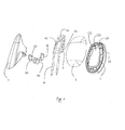
- FIG. 2 is a partly exploded view of the headrest in accordance with the illustrated embodiment of the present invention.
- FIG. 3 is an exploded view of the headrest in accordance with the illustrated embodiment of the present invention.
- FIG. 4 is another exploded view of the headrest in accordance with the illustrated embodiment of the present invention.
- the present application discloses a headrest which can be applied to electrical bicycles.
- the headrest includes a front casing 1, a rear casing 2 fixed to the front casing 1 and a headrest support fixed between the front casing 1 and the rear casing 2 for reliably keeping the contour of the headrest.
- the headrest support includes a metal plate 3 and a stationary rod 4.
- the metal plate 3 is fixed to a top of the stationary rod 4 and clamped between the front casing 1 and the rear casing 2.
- the stationary rod 4 is fixed to the rear casing 2 and extends downwardly beyond the rear casing 2.
- the stationary rod 4 is a round tube and is of a U-shaped configuration as a whole.
- the front casing 1 includes an outer cortical layer 11, a plastic piece 12 and a sponge sandwiched between the outer cortical layer 11 and the plastic piece 12.
- the front casing 1 has security protection function. That is to say, when the human head backwardly collides the front casing 1, since the front casing 1 is soft, it can be provided with excellent buffering protection of the head so as to avoiding accident injury.
- the plastic piece 12 includes a main portion 121 extending backwardly and a peripheral portion 122 enclosing the main portion 121.
- the metal piece 3 resists against the main portion 121.
- the peripheral portion 122 includes a plurality of hooks 123
- the rear casing 2 includes a plurality of fixing holes 21, and the hooks 123 are lockable with the fixing holes 21 so as to fasten the front casing 1 and the rear casing 2 together.
- the rear casing 2 includes a recessed section 22 and a peripheral section 23 enclosing the recessed section 22.
- the recessed section 22 includes an upper embossment 221 and a lower embossment 222 below the upper embossment 221.
- the stationary rod 4 includes a horizontal lever 41 abutting against a top side of the upper embossment 221 and a pair of vertical levers 42 extending downwardly from lateral sides of the horizontal lever 41. The vertical levers 42 clamp opposite sides of the upper embossment 221.
- the lower embossment 222 includes a pair of first holes 223, the peripheral section 23 includes a pair of second holes 231 corresponding to the first holes 223, and the vertical levers 42 extend through the first holes 223 and the second holes 231 in turn and further extend beyond the peripheral section 23.
- Each of the upper embossment 221 and the lower embossment 222 includes a restricting hole 224, and the metal piece 3 includes a mounting hole 31 corresponding to the restricting hole 224.
- the headrest further includes a fixing member for mating with the restricting hole 224 and the mounting hole 31.
- the fixing member can be a screw.
- the headrest includes a support member 5 supporting a bottom side and a rear side of the rear casing 2.
- the support member 5 includes a pair of through holes 51 through which the vertical levers 42 extend downwardly.
- the headrest further includes a restricting member 6 mounted to the support member 5.
- the support member 5 includes a protrusion 52 extending downwardly.
- the restricting member 6 includes a bottom U-shaped portion 61 and a pair of transverse portions 62 horizontally extending from opposite sides of the U-shaped portion 61.
- Each transverse portion 62 includes a sleeve portion 63.
- the U-shaped portion 61 surrounds a bottom side and opposite lateral sides of the protrusion 52.
- the sleeve portions 63 are received in the through holes 51.
- the vertical levers 42 extend through the sleeve portions 63 and extend beyond the support member 5.
- the vertical levers 42 are positioned at lateral sides of the U-shaped portion 61 and the protrusion 52.
- the restricting member 6 further includes a pair of vertical pieces 64 extending upwardly from opposite ends of the transverse portions 62 for fixing with other components of the electrical bicycle.
- the restricting member 6 is mainly used for downwardly resisting against the vehicle framework for preventing that the headrest offsets from the normal position because of the downward movement of the headrest.
Landscapes
- Engineering & Computer Science (AREA)
- Aviation & Aerospace Engineering (AREA)
- Transportation (AREA)
- Mechanical Engineering (AREA)
- Seats For Vehicles (AREA)
- Chair Legs, Seat Parts, And Backrests (AREA)
Abstract
Description
- The present invention relates to an electrical bicycle, and more particularly to a headrest of the electrical bicycle.
- Conventional electrical bicycles are basically designed and improved referring to the bicycles and the motorcycles. During riding a bicycle or a motorcycle, the driver's head will easily get fatigue because the head is often unable to nestle the bicycle or the motorcycle. In order to improve driver's driving pleasure, it is desirable to design a new headrest to solve the above problem.
- An object of the present application is to provide a comfortable and reliable headrest.
- In order to solve the above technical problem, it is provided according to the present application a headrest which includes a front casing, a rear casing fixed to the front casing and a headrest support fixed between the front casing and the rear casing. The headrest support includes a metal plate and a stationary rod. The metal plate is fixed to a top of the stationary rod and clamped between the front casing and the rear casing. The stationary rod is fixed to the rear casing and extends downwardly beyond the rear casing.
- Preferably, the stationary rod is a round tube and is of a U-shaped configuration as a whole.
- Preferably, the front casing includes an outer cortical layer, a plastic piece and a sponge sandwiched between the outer cortical layer and the plastic piece.
- Preferably, the plastic piece includes a main portion extending backwardly and a peripheral portion enclosing the main portion. The metal piece resists against the main portion.
- Preferably, the peripheral portion includes a plurality of hooks, the rear casing includes a plurality of fixing holes, and the hooks are lockable with the fixing holes so as to fasten the front casing and the rear casing together.
- Preferably, the rear casing includes a recessed section and a peripheral section enclosing the recessed section. The recessed section includes an upper embossment and a lower embossment below the upper embossment. The stationary rod includes a horizontal lever abutting against a top side of the upper embossment and a pair of vertical levers extending downwardly from lateral sides of the horizontal lever. The vertical levers clamp opposite sides of the upper embossment.
- Preferably, the lower embossment includes a pair of first holes, the peripheral section includes a pair of second holes corresponding to the first holes, and the vertical levers extend through the first holes and the second holes in turn and extend beyond the peripheral section.
- Preferably, each of the upper embossment and the lower embossment includes a restricting hole, the metal piece includes a mounting hole, and the headrest further includes a fixing member for mating with the restricting hole and the mounting hole.
- Preferably, the headrest includes a support member supporting a bottom side and a rear side of the rear casing. The support member includes a pair of through holes through which the vertical levers extend.
- Preferably, the headrest further includes a restricting member mounted to the support member. The support member includes a protrusion extending downwardly. The restricting member includes a bottom U-shaped portion surrounding the protrusion and a pair of transverse portions horizontally extending from opposite sides of the U-shaped portion. Each transverse portion includes a sleeve portion received in the through holes. The vertical levers extend through the sleeve portions and extend beyond the support member. The vertical levers are positioned at lateral sides of the U-shaped portion and the protrusion.
- Comparing with the prior arts, the headrest according to the present application is provided with a headrest support so as to have a certain degree of pressure resistance and softness at the same time. The headrest retains its original profile after long periods of use.
-
FIG. 1 is a perspective view of a headrest in accordance with an illustrated embodiment of the present invention; -
FIG. 2 is a partly exploded view of the headrest in accordance with the illustrated embodiment of the present invention; -
FIG. 3 is an exploded view of the headrest in accordance with the illustrated embodiment of the present invention; and -
FIG. 4 is another exploded view of the headrest in accordance with the illustrated embodiment of the present invention. - In order to better understand the object, the technical solution and the advantages of the present application, the detailed description of the invention referring to the drawings will be described hereinafter.
- Referring to
FIGS. 1 to 4 , the present application discloses a headrest which can be applied to electrical bicycles. The headrest includes afront casing 1, arear casing 2 fixed to thefront casing 1 and a headrest support fixed between thefront casing 1 and therear casing 2 for reliably keeping the contour of the headrest. The headrest support includes ametal plate 3 and astationary rod 4. Themetal plate 3 is fixed to a top of thestationary rod 4 and clamped between thefront casing 1 and therear casing 2. Thestationary rod 4 is fixed to therear casing 2 and extends downwardly beyond therear casing 2. Thestationary rod 4 is a round tube and is of a U-shaped configuration as a whole. - The
front casing 1 includes an outercortical layer 11, aplastic piece 12 and a sponge sandwiched between the outercortical layer 11 and theplastic piece 12. Thefront casing 1 has security protection function. That is to say, when the human head backwardly collides thefront casing 1, since thefront casing 1 is soft, it can be provided with excellent buffering protection of the head so as to avoiding accident injury. - The
plastic piece 12 includes amain portion 121 extending backwardly and aperipheral portion 122 enclosing themain portion 121. Themetal piece 3 resists against themain portion 121. Theperipheral portion 122 includes a plurality ofhooks 123, therear casing 2 includes a plurality offixing holes 21, and thehooks 123 are lockable with thefixing holes 21 so as to fasten thefront casing 1 and therear casing 2 together. - The
rear casing 2 includes arecessed section 22 and aperipheral section 23 enclosing therecessed section 22. Therecessed section 22 includes anupper embossment 221 and alower embossment 222 below theupper embossment 221. Thestationary rod 4 includes ahorizontal lever 41 abutting against a top side of theupper embossment 221 and a pair ofvertical levers 42 extending downwardly from lateral sides of thehorizontal lever 41. The vertical levers 42 clamp opposite sides of theupper embossment 221. - The
lower embossment 222 includes a pair offirst holes 223, theperipheral section 23 includes a pair ofsecond holes 231 corresponding to thefirst holes 223, and thevertical levers 42 extend through thefirst holes 223 and thesecond holes 231 in turn and further extend beyond theperipheral section 23. - Each of the
upper embossment 221 and thelower embossment 222 includes arestricting hole 224, and themetal piece 3 includes amounting hole 31 corresponding to therestricting hole 224. The headrest further includes a fixing member for mating with therestricting hole 224 and themounting hole 31. The fixing member can be a screw. - The headrest includes a
support member 5 supporting a bottom side and a rear side of therear casing 2. Thesupport member 5 includes a pair of throughholes 51 through which the vertical levers 42 extend downwardly. - The headrest further includes a restricting
member 6 mounted to thesupport member 5. Thesupport member 5 includes aprotrusion 52 extending downwardly. The restrictingmember 6 includes abottom U-shaped portion 61 and a pair oftransverse portions 62 horizontally extending from opposite sides of the U-shapedportion 61. Eachtransverse portion 62 includes asleeve portion 63. TheU-shaped portion 61 surrounds a bottom side and opposite lateral sides of theprotrusion 52. Thesleeve portions 63 are received in the through holes 51. Thevertical levers 42 extend through thesleeve portions 63 and extend beyond thesupport member 5. Thevertical levers 42 are positioned at lateral sides of theU-shaped portion 61 and theprotrusion 52. The restrictingmember 6 further includes a pair ofvertical pieces 64 extending upwardly from opposite ends of thetransverse portions 62 for fixing with other components of the electrical bicycle. The restrictingmember 6 is mainly used for downwardly resisting against the vehicle framework for preventing that the headrest offsets from the normal position because of the downward movement of the headrest. - In conclusion, the description of the above embodiment is only used for the understanding of the present application. It should be noted that, those skilled in the art may make many improvements and modifications to the present application without departing from the principle of the present application, and these improvements and modifications also fall into the protection scope of the claims of the present application.
Claims (10)
- A headrest comprising a front casing, a rear casing fixed to the front casing and a headrest support fixed between the front casing and the rear casing, the headrest support comprising a metal plate and a stationary rod, the metal plate being fixed to a top of the stationary rod and clamped between the front casing and the rear casing, the stationary rod being fixed to the rear casing and extending downwardly beyond the rear casing.
- The headrest as claimed in claim 1, wherein the stationary rod is a round tube and is of a U-shaped configuration as a whole.
- The headrest as claimed in claim 1, wherein the front casing comprises an outer cortical layer, a plastic piece and a sponge sandwiched between the outer cortical layer and the plastic piece.
- The headrest as claimed in claim 3, wherein the plastic piece comprises a main portion extending backwardly and a peripheral portion enclosing the main portion, the metal piece resisting against the main portion.
- The headrest as claimed in claim 4, wherein the peripheral portion comprises a plurality of hooks, the rear casing comprises a plurality of fixing holes, and the hooks are lockable with the fixing holes so as to fasten the front casing and the rear casing together.
- The headrest as claimed in claim 1, wherein the rear casing comprises a recessed section and a peripheral section enclosing the recessed section, the recessed section comprising an upper embossment and a lower embossment below the upper embossment, the stationary rod comprising a horizontal lever abutting against a top side of the upper embossment and a pair of vertical levers extending downwardly from lateral sides of the horizontal lever, the vertical levers clamping opposite sides of the upper embossment.
- The headrest as claimed in claim 6, wherein the lower embossment comprises a pair of first holes, the peripheral section comprises a pair of second holes corresponding to the first holes, and the vertical levers extend through the first holes and the second holes in turn and extend beyond the peripheral section.
- The headrest as claimed in claim 7, wherein each of the upper embossment and the lower embossment comprises a restricting hole, the metal piece comprises a mounting hole, and the headrest further comprises a fixing member for mating with the restricting hole and the mounting hole.
- The headrest as claimed in claim 7, further comprising a support member supporting a bottom side and a rear side of the rear casing, the support member comprising a pair of through holes through which the vertical levers extend.
- The headrest as claimed in claim 9, further comprising a restricting member mounted to the support member, the support member comprising a protrusion extending downwardly, the restricting member comprising a bottom U-shaped portion surrounding the protrusion and a pair of transverse portions horizontally extending from opposite sides of the U-shaped portion, each transverse portion comprising a sleeve portion received in the through holes, the vertical levers extending through the sleeve portions and extending beyond the support member, the vertical levers being positioned at lateral sides of the U-shaped portion and the protrusion.
Applications Claiming Priority (2)
| Application Number | Priority Date | Filing Date | Title |
|---|---|---|---|
| CN2011100554174A CN102673685A (en) | 2011-03-09 | 2011-03-09 | Headrest |
| PCT/CN2011/001128 WO2012119277A1 (en) | 2011-03-09 | 2011-07-08 | Headrest |
Publications (2)
| Publication Number | Publication Date |
|---|---|
| EP2660100A1 true EP2660100A1 (en) | 2013-11-06 |
| EP2660100A4 EP2660100A4 (en) | 2015-01-07 |
Family
ID=46797389
Family Applications (1)
| Application Number | Title | Priority Date | Filing Date |
|---|---|---|---|
| EP11860225.9A Withdrawn EP2660100A4 (en) | 2011-03-09 | 2011-07-08 | Headrest |
Country Status (7)
| Country | Link |
|---|---|
| US (1) | US8721001B2 (en) |
| EP (1) | EP2660100A4 (en) |
| CN (1) | CN102673685A (en) |
| BR (1) | BR112013020319A2 (en) |
| CA (1) | CA2824811A1 (en) |
| TW (1) | TWM435387U (en) |
| WO (1) | WO2012119277A1 (en) |
Cited By (1)
| Publication number | Priority date | Publication date | Assignee | Title |
|---|---|---|---|---|
| WO2017149241A1 (en) * | 2016-03-01 | 2017-09-08 | Cera Tsc | Headrest for a motor vehicle seat |
Families Citing this family (8)
| Publication number | Priority date | Publication date | Assignee | Title |
|---|---|---|---|---|
| US20130285431A1 (en) * | 2012-04-26 | 2013-10-31 | Martur Sunger Ve Koltuk Tesisleri Ticaret Ve Sanayi Anonim Sirketi | Rear headrest mechanism used in the passenger seats of motor vehicles |
| US9102255B2 (en) * | 2013-10-04 | 2015-08-11 | Ami Industries | Headrest assembly for an aircraft seat |
| DE102015200553B4 (en) * | 2015-01-15 | 2022-07-21 | Adient Luxembourg Holding S.À R.L. | Method of manufacturing a headrest |
| CN104743012B (en) * | 2015-03-24 | 2017-11-10 | 慈溪市桥头双对鞋厂 | Protector before a kind of motorcycle |
| US10173565B2 (en) * | 2016-05-18 | 2019-01-08 | Ford Global Technologies, Llc | Vehicle seat and headrest with dynamic impact energy management system |
| US10427575B2 (en) * | 2017-01-05 | 2019-10-01 | Ford Global Technologies, Llc | Removable head restraint bun feature |
| US11014482B1 (en) * | 2020-02-24 | 2021-05-25 | Lear Corporation | Passive head restraint insert for a vehicle seat assembly |
| US11708014B2 (en) * | 2021-08-06 | 2023-07-25 | Adient Us Llc | Head restraint system for a seat |
Family Cites Families (17)
| Publication number | Priority date | Publication date | Assignee | Title |
|---|---|---|---|---|
| US3253859A (en) * | 1964-03-20 | 1966-05-31 | Tom M Merriman | Safety pad |
| US5020855A (en) * | 1990-02-09 | 1991-06-04 | Prince Corporation | Adjustable headrest |
| US5257853A (en) * | 1992-02-07 | 1993-11-02 | Hoover Universal, Inc. | Headrest armature for seats |
| US6199900B1 (en) * | 1997-06-09 | 2001-03-13 | Gary D. Zeigler | Vehicle safety collision headrest system |
| JP2002000388A (en) * | 2000-06-23 | 2002-01-08 | Aisin Seiki Co Ltd | Headrest device |
| JP2003225137A (en) * | 2002-02-06 | 2003-08-12 | Aisin Seiki Co Ltd | Headrest device |
| DE10317036B3 (en) * | 2003-04-11 | 2004-06-03 | Grammer Ag | Headrest support, at the backrest of an automobile seat, has the leading wall of the headrest housing in swing wings from the center to carry the upholstery, on swing axes with film hinges and a friction position lock |
| JP4304257B2 (en) * | 2004-02-25 | 2009-07-29 | 日産自動車株式会社 | Headrest device |
| JP2005334304A (en) * | 2004-05-27 | 2005-12-08 | Nissan Shatai Co Ltd | Upper structure of vehicular seat |
| JP3836113B2 (en) * | 2004-06-14 | 2006-10-18 | 株式会社ホンダアクセス | Motorcycle backrest equipment |
| KR100794046B1 (en) * | 2006-08-10 | 2008-01-10 | 현대자동차주식회사 | Locking structure of the active headrest |
| JP4063863B1 (en) * | 2007-07-19 | 2008-03-19 | 備前発条株式会社 | Headrest |
| US8287040B2 (en) * | 2008-08-01 | 2012-10-16 | Proprietect Lp | Vehicular seat system and vehicular headrest |
| JP5428308B2 (en) * | 2008-11-28 | 2014-02-26 | 東海化成工業株式会社 | Headrest device |
| DE102010003109B9 (en) * | 2009-04-22 | 2012-12-13 | Lear Corporation | Seat arrangement with movable headrest |
| CN201961422U (en) * | 2011-03-09 | 2011-09-07 | 苏州益高电动车辆制造有限公司 | Head cushion |
| DE102011005590B4 (en) * | 2011-03-16 | 2013-05-16 | Lear Corporation | Seat assembly with a movable headrest assembly |
-
2011
- 2011-03-09 CN CN2011100554174A patent/CN102673685A/en active Pending
- 2011-07-08 TW TW100212514U patent/TWM435387U/en not_active IP Right Cessation
- 2011-07-08 WO PCT/CN2011/001128 patent/WO2012119277A1/en not_active Ceased
- 2011-07-08 EP EP11860225.9A patent/EP2660100A4/en not_active Withdrawn
- 2011-07-08 CA CA2824811A patent/CA2824811A1/en not_active Abandoned
- 2011-07-08 BR BR112013020319A patent/BR112013020319A2/en not_active IP Right Cessation
-
2013
- 2013-07-26 US US13/952,347 patent/US8721001B2/en not_active Expired - Fee Related
Cited By (3)
| Publication number | Priority date | Publication date | Assignee | Title |
|---|---|---|---|---|
| WO2017149241A1 (en) * | 2016-03-01 | 2017-09-08 | Cera Tsc | Headrest for a motor vehicle seat |
| FR3048389A1 (en) * | 2016-03-01 | 2017-09-08 | Cera Tsc | HEADREST FOR THE SEAT OF A MOTOR VEHICLE |
| US10773625B2 (en) | 2016-03-01 | 2020-09-15 | Tesca France | Headrest for a motor vehicle seat |
Also Published As
| Publication number | Publication date |
|---|---|
| EP2660100A4 (en) | 2015-01-07 |
| US8721001B2 (en) | 2014-05-13 |
| CA2824811A1 (en) | 2012-09-13 |
| CN102673685A (en) | 2012-09-19 |
| TWM435387U (en) | 2012-08-11 |
| BR112013020319A2 (en) | 2016-10-18 |
| WO2012119277A1 (en) | 2012-09-13 |
| US20130320738A1 (en) | 2013-12-05 |
Similar Documents
| Publication | Publication Date | Title |
|---|---|---|
| US8721001B2 (en) | Headrest | |
| US9481422B2 (en) | Motorcycle | |
| JP6262067B2 (en) | Vehicle seat | |
| JP2008302062A (en) | Rocking chair | |
| US20150375655A1 (en) | Backrest frame for a seat, in particular for a vehicle seat, and vehicle seat | |
| EP2489581A1 (en) | Screen attachment structure for saddle riding type vehicle | |
| US10118663B2 (en) | Handlebar mount structure for saddled vehicle | |
| JP5885771B2 (en) | Chair armrest | |
| US9457858B2 (en) | Mounted child bicycle seat assembly | |
| EP2159139B1 (en) | Device for fixing a child seat to the frame of a two-wheeled vehicle | |
| KR101468704B1 (en) | Headrest for chair | |
| KR20160072581A (en) | Foot rest assembly | |
| JP6080748B2 (en) | Child carrying device mounting structure and motorcycle | |
| JP5876276B2 (en) | Chair | |
| JP6144901B2 (en) | Motorcycle | |
| EP2366611B1 (en) | Bicycle seat assembly | |
| CN201961422U (en) | Head cushion | |
| KR20160098728A (en) | detachable seat shock absorber | |
| JP5873304B2 (en) | Chair with armrests | |
| EP1645496B1 (en) | Securing device for the pillion passenger of a motorbike | |
| JP6091851B2 (en) | Chair with backrest | |
| JP3864125B2 (en) | saddle | |
| JP2012091668A (en) | Vehicle seat | |
| JP4047334B2 (en) | Seat back | |
| CN202728486U (en) | Auxiliary handle fixing device for bicycle |
Legal Events
| Date | Code | Title | Description |
|---|---|---|---|
| PUAI | Public reference made under article 153(3) epc to a published international application that has entered the european phase |
Free format text: ORIGINAL CODE: 0009012 |
|
| 17P | Request for examination filed |
Effective date: 20130729 |
|
| AK | Designated contracting states |
Kind code of ref document: A1 Designated state(s): AL AT BE BG CH CY CZ DE DK EE ES FI FR GB GR HR HU IE IS IT LI LT LU LV MC MK MT NL NO PL PT RO RS SE SI SK SM TR |
|
| DAX | Request for extension of the european patent (deleted) | ||
| A4 | Supplementary search report drawn up and despatched |
Effective date: 20141204 |
|
| RIC1 | Information provided on ipc code assigned before grant |
Ipc: B60N 2/48 20060101AFI20141128BHEP Ipc: B60N 2/44 20060101ALI20141128BHEP |
|
| STAA | Information on the status of an ep patent application or granted ep patent |
Free format text: STATUS: THE APPLICATION IS DEEMED TO BE WITHDRAWN |
|
| 18D | Application deemed to be withdrawn |
Effective date: 20150703 |