EP2658421B1 - Capsule-controlled motorized brewing unit - Google Patents
Capsule-controlled motorized brewing unit Download PDFInfo
- Publication number
- EP2658421B1 EP2658421B1 EP12797811.2A EP12797811A EP2658421B1 EP 2658421 B1 EP2658421 B1 EP 2658421B1 EP 12797811 A EP12797811 A EP 12797811A EP 2658421 B1 EP2658421 B1 EP 2658421B1
- Authority
- EP
- European Patent Office
- Prior art keywords
- capsule
- assemblies
- sidewall
- motor
- receptacle
- Prior art date
- Legal status (The legal status is an assumption and is not a legal conclusion. Google has not performed a legal analysis and makes no representation as to the accuracy of the status listed.)
- Active
Links
- 239000002775 capsule Substances 0.000 title claims description 494
- 230000000712 assembly Effects 0.000 claims description 232
- 238000000429 assembly Methods 0.000 claims description 232
- 235000013361 beverage Nutrition 0.000 claims description 58
- XLYOFNOQVPJJNP-UHFFFAOYSA-N water Substances O XLYOFNOQVPJJNP-UHFFFAOYSA-N 0.000 claims description 54
- 238000012546 transfer Methods 0.000 claims description 53
- 239000004615 ingredient Substances 0.000 claims description 40
- 230000004913 activation Effects 0.000 claims description 37
- 230000000717 retained effect Effects 0.000 claims description 14
- 230000001955 cumulated effect Effects 0.000 claims description 12
- 238000000034 method Methods 0.000 claims description 12
- 235000016213 coffee Nutrition 0.000 claims description 9
- 235000013353 coffee beverage Nutrition 0.000 claims description 9
- 230000009471 action Effects 0.000 claims description 7
- 235000013616 tea Nutrition 0.000 claims description 7
- 239000008267 milk Substances 0.000 claims description 6
- 235000013336 milk Nutrition 0.000 claims description 6
- 210000004080 milk Anatomy 0.000 claims description 6
- 235000019219 chocolate Nutrition 0.000 claims description 5
- 235000014347 soups Nutrition 0.000 claims description 4
- 230000000903 blocking effect Effects 0.000 claims description 2
- 239000000470 constituent Substances 0.000 claims description 2
- 241001122767 Theaceae Species 0.000 claims 1
- 230000000875 corresponding effect Effects 0.000 description 25
- 238000002360 preparation method Methods 0.000 description 21
- 230000033001 locomotion Effects 0.000 description 16
- 230000005540 biological transmission Effects 0.000 description 14
- 238000003780 insertion Methods 0.000 description 14
- 230000037431 insertion Effects 0.000 description 14
- 230000002159 abnormal effect Effects 0.000 description 12
- 230000006870 function Effects 0.000 description 12
- 240000007154 Coffea arabica Species 0.000 description 8
- 230000000694 effects Effects 0.000 description 8
- 238000000605 extraction Methods 0.000 description 7
- 238000004519 manufacturing process Methods 0.000 description 7
- 230000008569 process Effects 0.000 description 7
- 244000299461 Theobroma cacao Species 0.000 description 6
- 230000002829 reductive effect Effects 0.000 description 6
- 230000001960 triggered effect Effects 0.000 description 6
- 244000269722 Thea sinensis Species 0.000 description 5
- 238000010521 absorption reaction Methods 0.000 description 5
- 230000001276 controlling effect Effects 0.000 description 4
- 230000005484 gravity Effects 0.000 description 4
- 238000010438 heat treatment Methods 0.000 description 4
- 238000002347 injection Methods 0.000 description 4
- 239000007924 injection Substances 0.000 description 4
- 239000007788 liquid Substances 0.000 description 4
- 238000013459 approach Methods 0.000 description 3
- 238000004140 cleaning Methods 0.000 description 3
- 230000007257 malfunction Effects 0.000 description 3
- 230000007246 mechanism Effects 0.000 description 3
- 238000002156 mixing Methods 0.000 description 3
- 238000012544 monitoring process Methods 0.000 description 3
- 238000004806 packaging method and process Methods 0.000 description 3
- 230000036961 partial effect Effects 0.000 description 3
- 230000002093 peripheral effect Effects 0.000 description 3
- 230000003068 static effect Effects 0.000 description 3
- 235000005764 Theobroma cacao ssp. cacao Nutrition 0.000 description 2
- 235000005767 Theobroma cacao ssp. sphaerocarpum Nutrition 0.000 description 2
- 208000027418 Wounds and injury Diseases 0.000 description 2
- XAGFODPZIPBFFR-UHFFFAOYSA-N aluminium Chemical compound [Al] XAGFODPZIPBFFR-UHFFFAOYSA-N 0.000 description 2
- 229910052782 aluminium Inorganic materials 0.000 description 2
- 239000004411 aluminium Substances 0.000 description 2
- 235000001046 cacaotero Nutrition 0.000 description 2
- 235000020291 caffè lungo Nutrition 0.000 description 2
- 230000006835 compression Effects 0.000 description 2
- 238000007906 compression Methods 0.000 description 2
- 238000001514 detection method Methods 0.000 description 2
- 238000006073 displacement reaction Methods 0.000 description 2
- 235000015114 espresso Nutrition 0.000 description 2
- 238000011049 filling Methods 0.000 description 2
- 238000001802 infusion Methods 0.000 description 2
- 208000014674 injury Diseases 0.000 description 2
- 239000000463 material Substances 0.000 description 2
- 230000000750 progressive effect Effects 0.000 description 2
- 238000007789 sealing Methods 0.000 description 2
- 238000012360 testing method Methods 0.000 description 2
- 235000008452 baby food Nutrition 0.000 description 1
- 230000006399 behavior Effects 0.000 description 1
- 230000008901 benefit Effects 0.000 description 1
- 230000015572 biosynthetic process Effects 0.000 description 1
- 235000015109 caffè americano Nutrition 0.000 description 1
- 235000015115 caffè latte Nutrition 0.000 description 1
- 235000015116 cappuccino Nutrition 0.000 description 1
- 238000010276 construction Methods 0.000 description 1
- 230000002596 correlated effect Effects 0.000 description 1
- 230000006378 damage Effects 0.000 description 1
- 230000003111 delayed effect Effects 0.000 description 1
- 230000004069 differentiation Effects 0.000 description 1
- 238000007599 discharging Methods 0.000 description 1
- 238000009826 distribution Methods 0.000 description 1
- 238000005265 energy consumption Methods 0.000 description 1
- 230000001747 exhibiting effect Effects 0.000 description 1
- 239000012530 fluid Substances 0.000 description 1
- 239000011521 glass Substances 0.000 description 1
- 230000002401 inhibitory effect Effects 0.000 description 1
- 230000003993 interaction Effects 0.000 description 1
- 238000011068 loading method Methods 0.000 description 1
- 230000015654 memory Effects 0.000 description 1
- 230000000737 periodic effect Effects 0.000 description 1
- 239000000843 powder Substances 0.000 description 1
- 238000012545 processing Methods 0.000 description 1
- 235000020288 ristretto Nutrition 0.000 description 1
- 239000000243 solution Substances 0.000 description 1
- 239000000126 substance Substances 0.000 description 1
- 239000008400 supply water Substances 0.000 description 1
- 230000000007 visual effect Effects 0.000 description 1
Images


Classifications
-
- A—HUMAN NECESSITIES
- A47—FURNITURE; DOMESTIC ARTICLES OR APPLIANCES; COFFEE MILLS; SPICE MILLS; SUCTION CLEANERS IN GENERAL
- A47J—KITCHEN EQUIPMENT; COFFEE MILLS; SPICE MILLS; APPARATUS FOR MAKING BEVERAGES
- A47J31/00—Apparatus for making beverages
- A47J31/44—Parts or details or accessories of beverage-making apparatus
- A47J31/4403—Constructional details
-
- A—HUMAN NECESSITIES
- A47—FURNITURE; DOMESTIC ARTICLES OR APPLIANCES; COFFEE MILLS; SPICE MILLS; SUCTION CLEANERS IN GENERAL
- A47J—KITCHEN EQUIPMENT; COFFEE MILLS; SPICE MILLS; APPARATUS FOR MAKING BEVERAGES
- A47J31/00—Apparatus for making beverages
- A47J31/24—Coffee-making apparatus in which hot water is passed through the filter under pressure, i.e. in which the coffee grounds are extracted under pressure
- A47J31/34—Coffee-making apparatus in which hot water is passed through the filter under pressure, i.e. in which the coffee grounds are extracted under pressure with hot water under liquid pressure
- A47J31/36—Coffee-making apparatus in which hot water is passed through the filter under pressure, i.e. in which the coffee grounds are extracted under pressure with hot water under liquid pressure with mechanical pressure-producing means
- A47J31/3604—Coffee-making apparatus in which hot water is passed through the filter under pressure, i.e. in which the coffee grounds are extracted under pressure with hot water under liquid pressure with mechanical pressure-producing means with a mechanism arranged to move the brewing chamber between loading, infusing and ejecting stations
- A47J31/3623—Cartridges being employed
- A47J31/3633—Means to perform transfer from a loading position to an infusing position
-
- A—HUMAN NECESSITIES
- A47—FURNITURE; DOMESTIC ARTICLES OR APPLIANCES; COFFEE MILLS; SPICE MILLS; SUCTION CLEANERS IN GENERAL
- A47J—KITCHEN EQUIPMENT; COFFEE MILLS; SPICE MILLS; APPARATUS FOR MAKING BEVERAGES
- A47J31/00—Apparatus for making beverages
- A47J31/44—Parts or details or accessories of beverage-making apparatus
- A47J31/52—Alarm-clock-controlled mechanisms for coffee- or tea-making apparatus ; Timers for coffee- or tea-making apparatus; Electronic control devices for coffee- or tea-making apparatus
- A47J31/525—Alarm-clock-controlled mechanisms for coffee- or tea-making apparatus ; Timers for coffee- or tea-making apparatus; Electronic control devices for coffee- or tea-making apparatus the electronic control being based on monitoring of specific process parameters
- A47J31/5251—Alarm-clock-controlled mechanisms for coffee- or tea-making apparatus ; Timers for coffee- or tea-making apparatus; Electronic control devices for coffee- or tea-making apparatus the electronic control being based on monitoring of specific process parameters of pressure
-
- A—HUMAN NECESSITIES
- A47—FURNITURE; DOMESTIC ARTICLES OR APPLIANCES; COFFEE MILLS; SPICE MILLS; SUCTION CLEANERS IN GENERAL
- A47J—KITCHEN EQUIPMENT; COFFEE MILLS; SPICE MILLS; APPARATUS FOR MAKING BEVERAGES
- A47J31/00—Apparatus for making beverages
- A47J31/44—Parts or details or accessories of beverage-making apparatus
- A47J31/52—Alarm-clock-controlled mechanisms for coffee- or tea-making apparatus ; Timers for coffee- or tea-making apparatus; Electronic control devices for coffee- or tea-making apparatus
- A47J31/525—Alarm-clock-controlled mechanisms for coffee- or tea-making apparatus ; Timers for coffee- or tea-making apparatus; Electronic control devices for coffee- or tea-making apparatus the electronic control being based on monitoring of specific process parameters
- A47J31/5253—Alarm-clock-controlled mechanisms for coffee- or tea-making apparatus ; Timers for coffee- or tea-making apparatus; Electronic control devices for coffee- or tea-making apparatus the electronic control being based on monitoring of specific process parameters of temperature
-
- A—HUMAN NECESSITIES
- A47—FURNITURE; DOMESTIC ARTICLES OR APPLIANCES; COFFEE MILLS; SPICE MILLS; SUCTION CLEANERS IN GENERAL
- A47J—KITCHEN EQUIPMENT; COFFEE MILLS; SPICE MILLS; APPARATUS FOR MAKING BEVERAGES
- A47J31/00—Apparatus for making beverages
- A47J31/44—Parts or details or accessories of beverage-making apparatus
- A47J31/52—Alarm-clock-controlled mechanisms for coffee- or tea-making apparatus ; Timers for coffee- or tea-making apparatus; Electronic control devices for coffee- or tea-making apparatus
- A47J31/525—Alarm-clock-controlled mechanisms for coffee- or tea-making apparatus ; Timers for coffee- or tea-making apparatus; Electronic control devices for coffee- or tea-making apparatus the electronic control being based on monitoring of specific process parameters
- A47J31/5255—Alarm-clock-controlled mechanisms for coffee- or tea-making apparatus ; Timers for coffee- or tea-making apparatus; Electronic control devices for coffee- or tea-making apparatus the electronic control being based on monitoring of specific process parameters of flow rate
Definitions
- the present invention relates to a user-convenient system relating to the cooperation of an ingredient capsule and a machine for the preparation of a beverage from the ingredient capsule.
- the invention also relates to the method of operating the system as well as to the use of a capsule for providing such a system or operating it.
- a "beverage” is meant to include any human-consumable liquid substance, such as tea, coffee, hot or cold chocolate, milk, soup, baby food, etc.
- a "capsule” is meant to include any pre-portioned beverage ingredient, such as a flavouring ingredient, within an enclosing packaging of any material, in particular an airtight packaging, e.g. plastic, aluminium, recyclable and/or biodegradable packagings, and of any shape and structure, including soft pods or rigid cartridges containing the ingredient.
- Certain beverage preparation machines use capsules containing ingredients to be extracted or to be dissolved and/or ingredients that are stored and dosed automatically in the machine or else are added at the time of preparation of the drink.
- Some beverage machines possess filling means that include a pump for liquid, usually water, which pumps the liquid from a source of water that is cold or indeed heated through heating means, e.g. a thermoblock or the like.
- a capsule containing beverage ingredients is inserted in a brewing device.
- the brewing device is tightly closed about the capsule, water is injected at the first face of the capsule, the beverage is produced in the closed volume of the capsule and a brewed beverage can be drained from a second face of the capsule and collected into a receptacle such as a cup or glass.
- Brewing devices have been developed to facilitate insertion of a "fresh" capsule and removal of the capsule upon use.
- WO 2005/004683 and WO 2007/135136 relate to such brewing devices.
- the devices comprise a frame, a fixed holding part for the capsule, a movable holding part which is mounted relative to the frame in a sliding relationship, one or two knuckle joint mechanisms that provide a mechanical system which enables to close in a steady and fluid-tight manner the holding parts about the capsule while also resisting to the counter-force acting while re-opening and generated by the internal brewing pressure, and a handle for directly levering the knuckle joint mechanism.
- Such a device forms a simple assembly enabling insertion of the capsule by vertical fall through a passage in the frame and removal of the used capsule in the same direction as the insertion direction.
- the handle may serve to cover and uncover the passage for the capsule.
- the movable parts of the brewing device are actuated manually via the handle.
- the manual force required to move the movable parts varies during closure and opening of the machine and depends on the dimensional tolerances of the capsules used and the positioning and nature of the capsules as well as the temperature of the brewing unit.
- WO 2009/043630 discloses a beverage preparation machine including a brewing unit having a front part with a passage for inserting a capsule into the brewing unit.
- the front part is arranged to telescope out of the machine's housing for uncovering the passage for inserting a capsule into the brewing unit and telescopes into the brewing unit for sliding the passage under the housing and thus covering the passage by the housing.
- the actuation of the movable part of the brewing device may be motorized.
- EP 1 767 129 relates to a motor-driven extraction module for a capsule-based beverage production device.
- the brewing device has a capsule insertion passage provided with a safety door assembled to the movable part of the brewing device via a switch for detecting an undesired presence of a finger in the passage during closure and prevent squeezing-injuries by stopping the motor before any finger is caught in the brewing device.
- Non-prepublished WO2012/025258 discloses a machine having two brewing unit assemblies that form portions of a brewing chamber and that are relatively movable by a motor from an open position for inserting an ingredient capsule to a closed position for preparing beverages from the capsule.
- This machine has control means for controlling the motor based on the comparison of the evolution over time of the power consumption of the motor to a set reference.
- the current consumption can evolve over time along: an initial portion forming a sharp increase of current consumption reflecting a start of motion of the brewing unit assemblies; a second portion that starts at a level slightly below a top of the initial portion and that slowly increases due to an increasing resistance by the capsule progressively entering the brewing chamber up to a maximum where the capsule is forced out of an intermediate position in which it is supported by stop members; another portion that slightly drops from the maximum to a minimum; a further portion that increases due to a deformation and progressive piercing of the capsule by blades associated with one of the brewing unit assemblies; a yet further portion that is more or less flat during a final approach of the assemblies; and a portion which increases due to a stressing of a biasing spring for taking up a play between the assemblies in the closed position and which reaches a maximum whereby a maximum of power is consumed by the motor indicating that the motor is blocked and that the assemblies are in their closed position.
- Added functionalities are derived from the comparison between
- An object of the invention is to provide a more convenient system for handling ingredient capsules in a machine for preparation a beverage from such a capsule, in particular a simple and safe motorized handling of the closure function of the brewing unit about such a capsule. Greater convenience can thus be provided in the loading, and optionally the ejection, of the ingredient capsule whereby the user's intervention can be reduced.
- Another object is to provide a safe operation by reducing the risk of injuries or malfunctioning while using a motorized beverage machine.
- Another object is to provide added value functionalities such as semi-automatic or automatic brewing, rinsing and/or de-scaling modes. Another object is to control optimal conditions for rinsing and/or descalping the machine.
- the invention relates in particular to an ingredient capsule and a beverage machine for preparing and dispensing a beverage and more particularly to a beverage machine having a motorized brewing unit, as well as to the use of such an ingredient capsule for this beverage machine.
- the machine is a coffee, tea, chocolate, cacao, milk or soup preparation machine.
- the machine is arranged for preparing within a beverage processing module a beverage by passing hot or cold water or another liquid through a capsule containing an ingredient, such as a flavouring ingredient, of the beverage to be prepared, such as ground coffee or tea or chocolate or cacao or milk power.
- Such beverage preparation typically includes the mixing of a plurality of beverage ingredients, e.g. water and milk powder, and/or the infusion of a beverage ingredient, such as an infusion of ground coffee or tea with water.
- a predetermined amount of beverage is formed and dispensed on user-request, which corresponds to a serving.
- the volume of such a serving may be in the range of 25 to 200 ml or up to 300 or 400 ml, e.g. the volume for filling a cup or mug, depending on the type of beverage.
- Formed and dispensed beverages may be selected from ristrettos, espressos, lungos, cappuccinos, café latte, americano coffees, teas, etc...
- a coffee machine may be configured for dispensing espressos, e.g. an adjustable volume of 20 to 60 ml per serving, and/or for dispensing lungos, e.g. a volume in the range of 70 to 150 ml per serving.
- the invention relates to a system comprising a capsule and a beverage machine.
- the beverage machine has a brewing unit and activation means.
- the capsule has a sidewall joined to a capsule bottom, and a capsule top.
- the capsule sidewall, bottom and top form a generally cup-shaped container for containing a beverage ingredient.
- the brewing unit has a first assembly and a second assembly cooperating together.
- One of the assemblies comprises a capsule receptacle having a sidewall and a mouth, such as a generally cup-shaped capsule receptacle, delimiting with the other assembly at least part of a brewing chamber for receiving and containing the ingredient capsule.
- assembly may refer to a single component assembling different functions, e.g. mechanical guiding function, mechanical holding function, mechanical piercing function, flow function, pressure function, etc..., and/or refer to a plurality of components assembling the desired function(s).
- the activation means include means for supplying water, in particular heated water, to the brewing chamber and means for driving at least one of the assemblies:
- the capsule, the brewing unit and the drive means are arranged so that:
- the capsule is evacuated from assemblies, e.g. evacuated below the assemblies under the effect of gravity.
- the capsule upon insertion and before bringing the assemblies into the closed position about the capsule, the capsule can be retained in the open position by stop members of the brewing unit.
- the capsule top has a periphery that extends beyond the sidewall to form a flange and/or the capsule sidewall has a peripheral collar that is angled out from the mouth to form a generally equivalent flange.
- Such a capsule flange may be used to be guided along the insertion passage and to rest on the stop members placed at the bottom of the insertion channel. The capsule flange can then be forced below the stop members during the closure of the assemblies in view of the later evacuation by gravity of the capsule below the stop members.
- Such a capsule retaining system and other suitable retaining systems are for example generally disclosed in WO 2005/004683 .
- Alternative suitable arrangements for guiding and supporting a capsule in an intermediate position inbetween open assemblies are disclosed in WO 2005/004683 as well as in WO2007/135136 , WO 2007/135135 and WO 2009/043630 .
- the activation means include a motor for driving the assemblies between the open and closed positions and control means for controlling the water supply means and the drive action of the motor.
- the control means comprise:
- the assemblies and the capsule are arranged so that, when the capsule is retained in the open position and the assemblies are then driven from the open position towards the closed position, the capsule sidewall and the mouth of the capsule receptacle are urged together and contact each other in a sliding friction relationship over a fraction of the capsule sidewall.
- the outer surface of capsule sidewall and the inner surface of the receptacle's mouth are urged together in this manner.
- This electrical parameter representative of the power consumption of the motor may be compared to the set reference during the entire transfer of the assemblies from the open to the closed position or only during one or more portions of the transfer and/or even at the end of the transfer, i.e. in particular at periods of time when events may occur that are decisive for the process of generating the input to the activation means. It may be sufficient to monitor the power consumption during the portions of the transfer during which specific variable events can be expected (e.g. presence or absence of a capsule, jamming of a capsule, presence of a human body part such as a finger%) which is pertinent to a decision-making process for determining the input to the activation means.
- specific variable events e.g. presence or absence of a capsule, jamming of a capsule, presence of a human body part such as a finger
- the power consumption may also be monitored during the entire transfer when the entire power consumption of the transfer is decisive for process of generating the input to the activation means.
- the corresponding input may relate to stopping or continuing or reversing the powering of the motor, or allowing the supply of water to the brewing chamber once the assemblies are closed.
- This allowed supply of water upon closure may be automatically initiated by the control means or initiated upon user-request via a user-interface.
- the water may be supplied to the chamber for preparing a beverage by mixing with the ingredient in the capsule.
- further inputs for stopping, continuing or reversing the powering of the motor or for allowing or disallowing water supply for beverage preparation or for affecting the properties of the water supply e.g. water flow, temperature, pressure, amount
- several capsule-related tests in particular successive control tests, may be carried out during the closure of the assemblies.
- beverage preparation parameters e.g. temperature, pressure and/or ingredient quantities for a given beverage preparation and resulting beverage serving.
- the assemblies When the ingredient capsule is properly inserted into the machine, the assemblies will experience a certain force against closure influenced by the expected resistance against closure generated by the capsule whose sidewall slides against the mouth of the receptacle. In this case, water can be circulated under beverage preparation conditions into the capsule to form a beverage. When no ingredient capsule is inserted into the machine, the assemblies will experience a different (usually lower) force against closure influenced by the absence of capsule-generated resistance against closure. In this case, either no water is circulated or water for servicing, e.g. at specific service conditions regarding the water volume, pressure, flow and/or temperature, may be circulated into the brewing unit.
- Capsule misplacing may be caused by improper introduction of a new capsule into the machine or it may be caused by the presence of an improperly evacuated previously used capsule that remains in the way between the assemblies.
- Improper capsule evacuation may be experienced with a full used-capsule collector to which the capsules are evacuated upon use; when the collector is full the capsule evacuation from between the assemblies is jeopardized until the collector is emptied.
- the circumstances under which the assemblies are moved to the open and/or closed position in connection with a capsule between the assemblies, or even without such a capsule can be monitored by monitoring the power consumption of the motor.
- the required mechanical output energy of the motor to produce a movement is directly linked to its consumed input energy, e.g. electric energy, can be measured.
- the set reference may be based on a power consumption modelisation and/or an empiric power consumption measure under predetermined conditions, e.g. with or without ingredient capsule in the brewing unit, specific environment of use, etc...
- the set reference typically includes a tolerance margin to take into account expected variations that may occur e.g. due to the environment of use and/or manufacturing tolerances and/or handling tolerances and in particular to the friction coefficients between the capsules and the assemblies during closure.
- the motor is controlled to produce a motor output movement, e.g. rotation of a rotor, at a predetermined speed and/or to operate at a predetermined input voltage, e.g. at one or more constant voltage levels.
- a motor output movement e.g. rotation of a rotor
- the input powering of the motor can be adjusted in line with the needed output powering, e.g. angular speed and torque (depending on the constraints under which the motor has to operate in a given circumstance).
- the power supply of the motor may be arranged to control the motor's input voltage and the motor can be arranged to draw the required amount of current needed to maintain the input voltage.
- the mechanical constraints exercised against the motor output can be determined.
- Such constraints may correspond to normal operation of the motorized machine, e.g. opening or closing the brewing unit assemblies with or without a capsule ingredient, or to an abnormal operation, e.g. an interference with an obstacle preventing normal opening or closing, such as a misplaced capsule or a human body part e.g. a finger, caught inbetween the assemblies or inhibiting reopening of the assemblies, e.g. jamming of the brewing unit.
- the motorized beverage machine may be configured to allow a corresponding operation, e.g.
- a safety mode may be provided, e.g. to stop closure or reopen the assemblies when an undesired obstacle is caught between the assemblies, or stop the motor when the brewing unit is jammed e.g. to prevent undesired stress in the machine and allow for example manual unjamming by a user and/or service person, as appropriate.
- At least one of the electrical parameter(s) and at least one of the set reference(s) can be continuously or intermittently compared, in particular periodically compared, during the transfer of the assemblies from the open to the closed positions, in particular to detect a blocking obstacle inbetween the assemblies during the transfer.
- the electrical parameter(s) and the set reference (s) (42) are compared at a frequency in the range of 3 to 1000 s -1 , in particular 5 to 300 s -1 , such as 10 to 100 s -1 .
- Intermittent comparison e.g. periodic comparison, can be carried out digitally, by a digital control system (e.g. digital hardware gates and/or programmable digital processors). Continuous comparison may be carried out analogically by a corresponding electric control circuit.
- At least one electrical parameter and at least one set reference are compared once the assemblies have been transferred from the open to the closed positions, in particular to detect a presence or absence of the capsule in-between the assemblies.
- the electrical parameter(s) and the set reference(s) may be representative of a cumulated consumption of power by the motor during the transfer from the open to the closed positions of the assemblies, e.g. the parameter is representative of the total energy consumed by the motor during the transfer from the open to the closed positions.
- Such parameter may be used to determine whether or not a capsule is present in the assembly. As discussed above, when a capsule is present between the assemblies it creates an additional resistance against closure that needs to be overcome by the motor as compared to the resistance the motor has to overcome when there is no capsule between the assemblies.
- the comparison of the measured parameter to the set reference may be used to distinguish the presence from the absence of a capsule between the assemblies at the end of the transfer from the open to the closed positions.
- the machine When no capsule is detected in-between the closed assemblies, the machine may enter a rinsing or descaling mode. When a capsule is detected in-between the closed assemblies, the machine may enter a beverage preparation module.
- the sidewall of the capsule has a centrally-extending capsule axis generally perpendicular to the capsule top or capsule bottom.
- the mouth of the capsule receptacle may have a central receptacle axis perpendicular to the mouth.
- the central capsule axis may be an axis of symmetry of the capsule sidewall.
- the central receptacle axis may be an axis of symmetry of the receptacle mouth or receptacle sidewall.
- the central capsule axis and the central receptacle axis can be at an angle when the assemblies are in the open position and the capsule is retained therebetween.
- the two axis can be brought together, in particular until general superposition of the axis, during closure of the assemblies.
- the capsule can be moved from a first position, e.g. the retained position of the capsule between the open assemblies, to a second position, e.g. a brewing or extraction position, between the assemblies under the effect of the closure of the assemblies and the forces generated by the closure of the assemblies onto the capsule.
- the first and second positions may be different or the same, depending on the relative motion of the assemblies for closure about the capsule.
- the capsule top is held by a capsule holder whereas the capsule bottom, or a predominant part of the capsule bottom, is unsupported whereby the capsule is allowed to be downwardly inclined towards the capsule bottom under the effect of gravity.
- the receptacle with the mouth can be moved horizontally so that the upper part of the mouth pushes onto the upwardly oriented part of the capsule sidewall to force the capsule down.
- the capsule may be slightly off-set relative to the receptacle's mouth.
- the capsule and machine system can be so configured that, when the assemblies are driven towards the closed position with a capsule thereinbetween and until the central capsule axis and the central receptacle axis are brought generally in superposition, the capsule sidewall and the mouth of the capsule receptacle can be urged together and contact each other in a sliding friction relationship over a fraction of the capsule sidewall at a distance from the capsule bottom.
- a distance from the capsule bottom may correspond to at least 2%, in particular in the range of 5 to 50 such as 7 to 45%, of the length of the sidewall extending from the capsule bottom to the capsule top.
- the capsule and machine System can be so configured that, when the assemblies are driven towards the closed position with a capsule thereinbetween and until the central capsule axis and the central receptacle axis are brought generally in superposition, the capsule sidewall and the mouth of the capsule receptacle are urged together and contact each other in a sliding friction relationship over a fraction of the capsule sidewall at a distance from the capsule top.
- Such distance from the capsule top can correspond to at least 10%, in particular in the range of 15 to 35%, of the length of the sidewall extending from the capsule bottom to the capsule top.
- the capsule and machine system can be so configured that, when the assemblies are driven towards the closed position with a capsule thereinbetween, the fraction of the capsule sidewall in sliding friction relationship with the receptacle's mouth extends over a distance that corresponds to at least 20%, in particular in the range of 30 to 85% such as 45 to 80%, of the length of the sidewall extending from the capsule bottom to the capsule top.
- the sidewall may have an external surface formed by a straight or slightly curved or arched line, i.e. a generator line (or generatrix), that moves along and between the peripheries of the capsule top and capsule bottom, to form a generally cylindrical or frusto-conical surface.
- a generator line or generatrix
- the capsule and/or receptacle sidewalls do(es) not necessarily have a circular basis.
- the basis may be generally elliptic or polygonal. This leads to generally pyramidal or cylindrical sidewalls.
- the particular shape of the capsule is not decisive for detecting the presence or the absence of a capsule inbetween the assemblies.
- an infinity of capsule shapes may result in an identical cumulated power consumption.
- the present invention may be implemented in a manner that allows a variety of different capsule shapes without discrimination between the shapes.
- the present invention may be implemented in a manner that allows an identification of different capsule shapes with more or less tolerances on the particular dimension of the shapes.
- the invention may also be implemented in a way that the power monitoring is affected simultaneously by the shape of the capsule its resistance against deformation and/or its friction coefficient. Therefore, different capsule shapes may result in the same power detection, when the divergences of the corresponding capsule shapes are compensated by the resistance against deformation and/or the friction coefficient.
- capsules of the same shape may be distinguished from their resistance against deformation, i.e. material making the capsule and/or thickness of the capsule walls, and/or from their friction coefficient.
- the sliding friction relationship between the receptacle's mouth and the capsule sidewall may extend along a fraction of a generator line of the capsule sidewall, in particular an upwardly-situated generator line of the sidewall when entering the mouth.
- the capsule sidewall and the mouth of the capsule receptacle may be urged together and contact each other in a sliding friction relationship over a top spot of the mouth.
- At least one of the assemblies has piercing means, such as blades, for piercing the capsule.
- the piercing means can be forced into the capsule by piercing thereof when the assemblies are driven towards the closed position with a capsule thereinbetween, whereby a capsule-generated resistance against closure of the assemblies is created. This resistance may affect the power consumption of the motor during closure and the measured parameter over time so as to generate a corresponding input to the activation means, e.g. as discussed above.
- the piercing means can be forced into the capsule upon completion of the sliding friction relationship over the abovementioned fraction of the capsule sidewall.
- the capsule receptacle of one assembly can have one or more friction holding members for unsticking and separating the capsule from the cooperating assembly upon reopening of the assemblies.
- the friction holding member(s) may be forced against the capsule to slightly grip the capsule.
- a capsule-generated resistance against closure of the assemblies can be created. This resistance may affect the power consumption of the motor during closure and the measured parameter over time so as to generate a corresponding input to the activation means, e.g. relating to the water supply as discussed above.
- the friction ejection member(s) may be forced against the capsule upon completion of the sliding friction relationship over the abovementioned fraction of the capsule sidewall.
- proper piercing and/or gripping of the capsule may also be checked during closure of the assemblies and before allowing water to the brewing chamber.
- the motor may be stopped or reversed or the water supply may be disallowed when an unexpected closure force is detected instead of a force resulting, inter-alia, from:
- the assemblies and the capsule can be arranged so that, when the assemblies are in the open position with a misinserted capsule and the assemblies are then driven from the open position to the closed position, a capsule-generated resistance against closure of the assemblies, in particular preventing the closure of the assemblies, is created.
- This resistance may affect the power consumption of the motor during closure and the abovementioned measured parameter over time to provide a safety input to the motor of the activation means, in particular an input for stopping the motor or inverting the motor to move the assemblies back to the open position.
- a safety input is provided to the motor when detecting an abnormal variation of the measured parameter relative to the set reference.
- the variation may be deemed abnormal when the measured parameter:
- Providing a reference set that includes a tolerance range, e.g. 20, 30, 40 or even 50% relative to a median or average reference set may be appropriate to take into account normal variations of mechanical effects occurring in the machine, such as variations of a friction coefficient, temperature and humidity as well as manufacturing tolerances and tolerances on the friction coefficient of the capsules and brewing unit assemblies.
- the safety input may comprise inverting the motor action to move the movable assembly in open position or reducing or stopping the drive action of the motor.
- a set reference may be a maximum power consumption that is allowed for the motor during the transfer of the assemblies.
- the motor requires power that exceeds this maximum to proceed further, it may mean that an undesired obstacle interferes with the movement of the assemblies or that the assemblies have reached their closed positions.
- the assemblies may be exposed to an undesired obstacle during their transfer and a corresponding input to the activation means may be generated, such as stopping or inverting the motor.
- the assemblies When the exceeding power is required after this predetermined safety period has lapsed from the beginning of the powering of the motor for a given transfer of the assemblies, the assemblies are likely to have reached their closed position and a corresponding input to the activation means may be generated, such as allowing or the circulation of water for a beverage preparation or for a rinsing, cleaning or descaling process.
- the circulation of water may be automatic upon closure of the assemblies or merely authorized in view of a subsequent corresponding user-request.
- the control means can be configured to detect the abnormal variation in comparison to a referential curve representing the normal evolution of the electrical parameter as a function of time corresponding to:
- a water supply mode for the supply of heated water to the brewing chamber may be initiated when no abnormal variation of the measured parameter relative to the set reference has been detected and the assembly is in a closed position "Capsule closure mode or empty closure mode").
- the supplying of heated water may involve the circulation, e.g. by using a pump, of water from a source, e.g. a water tank, and/or the heating of water, e.g. continuous or batch heating, to the brewing chamber.
- the supply of heated water may be controlled, e.g. via one or more temperature sensors, pressure sensors and/or flowmeters, to adjust the heating and flow characteristics of the supplied heated water.
- the temperature of the circulated water can be adjusted to a particular beverage preparation process.
- the temperature of the circulated water may be adjusted to a cleaning and/or rinsing process.
- control means comprise a user-interface to selectively initiate the water supply mode.
- water may be circulated to the brewing chamber automatically or upon a user-request via the user-interface.
- the water supply may be automatically prevented when a capsule is misinserted into the machine, e.g. misplaced or severely altered in its characteristics, for instance the capsule shape or outer properties, necessary for proper handling of the capsule.
- the control means may be configured to initiate a brewing mode when the measured parameter matches the referential curve (including a possible tolerance) corresponding to the "capsule closure mode".
- the control means can be configured to initiate a rinsing and/or de-scaling mode when the measured parameter matches the referential curve corresponding to the "empty closure mode".
- the control means can be configured so that this supplied water is heated at a temperature, such as in the range of 55 to 85°C, lower than the normal brewing temperature, such as in the range of 85 to 98°C.
- control means can be configured to initiate a malfunction mode, e.g. generating at least one input for stopping or reversing the motor, shutting down the machine or parts thereof, indicate malfunction to the user via a user-interface such as a visual and/or audio interface.
- a malfunction mode e.g. generating at least one input for stopping or reversing the motor, shutting down the machine or parts thereof, indicate malfunction to the user via a user-interface such as a visual and/or audio interface.
- At least one measured parameter may represent the current consumption of the motor.
- the transmission means may include a gear assembly.
- the transmission means in particular a gear assembly, may be configured to provide a transmission ratio of at least 1:100, preferably comprised between 1:200 and 1:300.
- the control means can be free of end position sensors in the open position and/or in the closed position.
- the measure of the power consumption by the motor may be used to determine the open position and/or closed position.
- the measure of the power consumption may be correlated with a time evolution to link the consumption to a time-based expected position of the movable assembly, for instance to distinguish the power consumption resulting from reaching an end position from the power consumption resulting from interference with an intermediate undesired obstacle.
- control means may include at least one end position sensor, e.g. two end position sensors in particular for detecting the open position and/or the closed position.
- the control means can be configured to detect any abnormal variation in comparison to a referential curve representing the normal evolution of the electrical parameter as a function of time and to:
- the invention also relates to a method of operating the system as described above, as well as to the use, for providing such a system or for carrying out the method, of a capsule sidewall of an ingredient capsule as a resistance-generator affecting an input of the activation means.
- a capsule sidewall of an ingredient capsule as a resistance-generator affecting an input of the activation means.
- such a capsule may contain at least one of coffee, tea, chocolate, milk and soup constituents as an ingredient.
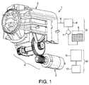
- machine 1 comprises a brewing unit 2 which is connected to an electric motor 3 that drives transmission means 4 for moving brewing unit 2 from an open position to a closed position and/or vice versa.
- Water supply means 5 are also provided as a part of machine 1.
- Such means 5 may include a water reservoir 6, a water pump 7 and a water heater 8.
- Water circulates in a water circuit 9 which is linked to brewing unit 2.
- circuit 9 is in fluid connection with brewing unit 2, e.g. via a brewing unit check valve 9' and capsule piercer 15 (see Figs 6 to 11 ).
- Control means 10 are also provided in machine 1.
- Control means 10 may include a control unit 11, sensors (not represented) and optionally a user interface 12.
- Control unit 11 may include processor(s), memories and programs to provide appropriate inputs to and receive outputs from the different activation means of the machine, in particular, the pump, heater and motor.
- Control unit 11 may be connected, e.g. wired or wireless, to user interface 12, pump 7, heater 8 and various sensors, such as flow-meters, temperature sensors, pressure sensors, ammeter (e.g. for measuring the current consumption of motor 3) such as a Hall sensor.
- control unit 11 may control electric power switches and/or current and voltage regulators associated with motor 3, pump 7 and heater 8.
- Fig. 12 shows in detail an example of a capsule 30 according to the invention.
- Capsule 30 has a sidewall 301 joined to a capsule bottom 302, and a capsule top 303.
- Sidewall 301, bottom 302 and top 303 form a generally cup-shaped container for containing a beverage ingredient.
- Sidewall 301 is generally frusto-conically shaped.
- Capsule bottom 302 is slightly domed.
- Capsule top 303 forms a lid having a periphery extending beyond sidewall 301, thereby forming a laterally protruding peripheral flange or rim 304.
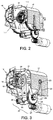
- brewing unit 2 has a first assembly 13 and a second assembly 14 which are movable relatively one another.
- One of assemblies 13,14 comprises a generally cup-shaped capsule receptacle 291, e.g. a capsule cage, having a sidewall 292 and a mouth 293 and delimiting with the other assembly 14 at least part of a brewing chamber 29 for containing capsule 30.
- first assembly 13 is a rear injection assembly 13 and includes capsule receptacle 291 with injection blades 15 at its bottom.
- Front assembly 14 forms a beverage delivery assembly and includes a capsule delivery plate 16.
- Front assembly 14 is associated to an outer casing 17 and is movable therewith relatively to rear injection assembly 13 which remains fixed to a frame 18 of machine 1.
- Front delivery assembly 14 includes a beverage outlet 19.
- Front delivery assembly 14 is moved relatively to rear injection assembly 13 by means of motor 3 via transmission means 4.
- the activation means are configured to supply water, in particular heated water, to brewing chamber 29 and to drive at least one assembly 14 of assemblies 13,14:
- passage 31 is provided between first and second assemblies 13,14 for allowing the insertion of capsule 30.
- capsule rim or flange 304 may be guided downwards in lateral channels 31".
- capsule 30 may be positioned in a first or intermediate position ( Fig. 7 ) e.g. on a corresponding stop means 31"', for example as described in EP 1 646 305 or WO 2009/043630 .
- a brewing chamber 29 is formed in the closed position ( Figs 3 , 4 and 11 ).
- Brewing chamber 29 is occupied at least partly by a capsule 30 in a normally closed position of brewing unit 2 ( Figures 4 and 11 ), when assemblies 13,14 are in the closed position.
- capsule 30 can be in a second or extraction position, in particular a position closer to assembly 14 or plate 16 than in the first position.
- Capsule 30 should be compatible with brewing chamber 29 and passage 31 for being handled properly by assemblies 13,14 during closure and opening of assemblies 13,14 of brewing unit 2.
- Suitable examples of capsules and brewing chambers are for instance generally disclosed in EP 0 512 468 , EP 0 512 470 and EP 2 068 684 .
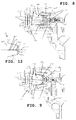
- Transmission means 4 may include various mechanical systems. Transmission means 4 may have a force transmission ratio from the motor to the assembly of at least 1:50, in particular from 1:100 to 1:300 to 1:500.
- transmission means 4 includes a gear assembly 20 linked to a cam 22 and cam-follower 23.
- cam 22 comprises a pair of elongated grooves located on each side of casing 17.
- Gear assembly 20 comprises a worm drive 21 connected to the motor axle (i.e. to the rotor of motor 3).
- Worm drive 21 operates a large gear 24, e.g. a spur gear or helical gear, which is fixed to an axle 25 on which sit two lateral smaller gears 26, 27, e.g. spur gears or helical gears or friction gears.
- the smaller gears 26, 27 drives a pair of gear segments 28, e.g.
- gear segments 28 with cam-followers 23 are positioned such that the brewing pressure is absorbed across the gear segments without it being transmitted to the rest of the drive system, e.g. radially across the gear segments.
- the brewing pressure can be absorbed by the drive system by a suitable configuration.
- motor 3 and at least part of transmission means 4 are assembled directly or indirectly on one of assemblies 13,14.
- motor 3 may be mounted on a frame 18 that can be fixed to assembly 13 and axle 25 may be mounted on a corresponding part 25' of frame 18.
- the gear ratio between worm drive 21 and large gear 24 may be in the range of 1:25 to 1:100, such as 1:50 to 1:80.
- the gear ratio between small gear 27 and gear segment 28 can be in the range of 1:3 to 1:10, in particular in the range of 1:5 to 1:8.
- worm drive 21 in transmission 4 can make this transmission unidirectional. In other words, force and movement can only be transmitted from motor 3 to transmission 4 and not vice versa, worm drive 21 acting as a stop in the opposite direction. Hence, no further stop means is needed to maintain assemblies 13,14 in a given position. It is sufficient to interrupt the powering of motor 3 to secure assemblies 13,14 in a given position, in particular in the closed or open position.
- both open and closed end positions are geometrically made as "hard stops” with no end switches or sensors.
- the input for the motor control may involve the user-interface, the current absorption of the motor and a timer of the control unit.
- Capsule 30, brewing unit 2 and drive means 3,4 are arranged so that:
- capsule 30 is evacuated from between assemblies 13,14, e.g. evacuated below assemblies 13,14 under the effect of gravity, to a collection area 32 (indicated in Fig. 6 ).
- the activation means include motor 3 for driving assemblies 13,14 between the open and closed positions and control means 10 for controlling the drive action of motor 3, control means 10 comprising:
- Figs 6 to 11 illustrate such an insertion sequence.
- Fig. 6 illustrates the insertion of capsule 30 into opening or mouth 31' of passage 31 between assemblies 13,14 in the open position.
- Fig. 7 illustrates capsule 30 in an intermediate position between assemblies 13,14 still in the open position, capsule flange 304 being for instance held by lateral stop members 31"' in passage 31.
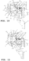
- Figs 8 to 10 illustrate how capsule bottom 302 and a sidewall 301 progressively enter receptacle 291 of assembly 13 via receptacle opening 293.
- Fig. 11 shows capsule 30 in the brewing or extraction position between assemblies 13,14 in their closed position.
- assemblies 13,14 and capsule 30 are arranged so that, when capsule 30 is retained in the open position and assemblies 13,14 are then driven from the open position towards the closed position, capsule sidewall 301 and mouth 293 of capsule receptacle 291 are urged together and contact each other in a sliding friction relationship over a fraction VIII'-IX' of capsule sidewall 301 so as to create a capsule-generated resistance against the closure of assemblies 13,14, which resistance affects the power consumption of motor 3 during closure and the measured parameter over time to generate a corresponding input to the activation means, e.g. relating to supply of water to the brewing chamber as discussed above.
- the activation means e.g. relating to supply of water to the brewing chamber as discussed above.
- Fig. 12 shows on capsule 30 the location of fraction VIII'-IX'. Further illustrated in Fig. 12 are the intermediate contact positions VIII and IX of the sliding friction relationship between sidewall 301 and mouth 293 which correspond to the configurations of the system shown in Figs 8 and 9 . Positions VIII, VIII', IX and XI' are also indicated in Figs 5 and 5a .
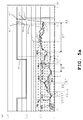
- two different typical curves 40,40a,41,41a representative of the power consumption by motor 3 can be detected and analyzed over time, e.g. by measuring the current consumption of motor 3, in particular when motor 3 is a DC motor, e.g. operated at generally constant voltage.
- Curves 40,40a,41,41a are representative of the power consumption of motor 3 evolving over time during the transfer of assemblies 13,14 from the open to the closed positions.
- each curve 40,40a,41,41a delimited on the right by corresponding dashed line 40',41' represents the cumulated power consumption revolving over time of motor 3 during the transfer between the open and the closed positions. Normally, such a cumulated power consumption is representative of the total energy needed by motor 3 for the transfer from the open to the closed positions.
- These areas 40,40';41,41';40a,40'; 41a,41a' delimited by curves 40,40a,41,41a and lines 40',41' can be measured and cumulated over time during the transfer between the open and closed positions. These areas can then be compared to area 42' which forms a set reference.
- curves 40,40a,41,41a represent an evolution of the current consumption by motor 3
- the corresponding areas 40,40';41,41';40a,40';41a,41a' may represent the energy consumed by motor 3 for the transfer from the open to the closed positions.
- Reference 42' may serve to delimit the energy consumption by motor 3 for transferring assemblies 13,14 from the open to the closed positions when capsule 30 is present inbetween assemblies 13,14 (which normally requires more energy for closure) or absent (which normally requires less energy for closure).
- Figs 5 and 5a illustrate measured current consumption curves 40,40a,41,41a of motor 3 during the closure of assemblies 13,14.
- Curves 40,40a,41,41a can be compared to a set reference, such as curve 42.
- Motor 3 can be operated at one or more generally constant voltage levels.
- motor 3 can be operated at a constant voltage, e.g. a voltage at a level in the range of 8 of 30 volts, during the entire travelling of assemblies 13,14 between the open and closed positions, as illustrated in Fig. 5 .
- a second mode exemplified in Fig. 5a
- motor 3 can be operated at a plurality of voltages between the open and closed positions of assemblies 13,14.
- the voltage at which motor 3 is operated is variable during the closure.
- motor 3 can be powered to move at a reduced speed. Inbetween these reduced speed periods, e.g. inbetween the start and end portions of the relative movement of assemblies 13,14, motor 3 can be powered to move at a higher speed to reduce the overall time needed for opening and closing the assemblies 13,14.
- motor 3 is a DC motor, it is powered at a lower voltage at the beginning and towards the end of the powering and at a higher voltage thereinbetween.
- the voltage is switched from a lower level to a higher level at point 4a and then from the higher level to the lower level at point 4b.
- the voltage switch may result in a current consumption peak (consumption increase or decrease).
- the lower voltage is in the range of 20 to 80% of the higher voltage, in particular 30 to 70% or 40 to 60%.
- the lower voltage is of about 50% or 66% of the higher voltage.
- the higher voltage is in the range of 8 to 50 volts, such as 10 to 30 volts.
- the higher voltage is at 12 volts and the lower voltage at 6 volts, or the higher voltage is at 18 volts and the lower voltage is at 12 volts.
- Curves 40,40a represent the evolution over time of the current consumption of motor 3 in the "capsule closure mode".
- the different positions of capsule 30 and assemblies 13,14 in correspondence with curves 40,40a are shown in Figs 6 to 11 .
- the closed state of brewing unit 2 in the capsule closure mode is represented in Figures 4 and 11 with capsule 30 enclosed in the closed brewing chamber.
- Curves 41,41a represent the evolution of the current consumption of motor 3 in the "empty closure mode".
- the closed state of brewing unit 2 in the empty closure mode is represented in Figure 3 .
- the "empty closure mode” may be distinguished from the “capsule closure mode” from the profile of curves 40,40a,41,41a and/or, as discussed above, from the size of the areas underneath these curves.
- curves 40,40a,41,41a reflect the power consumption of motor 3 during a closure movement of assemblies 13,14 of brewing unit 2.
- corresponding power consumption curves can be determined for the opening movements, e.g. with and without capsule 30 inbetween assemblies 13,14.
- Such opening curves can be used as a reference set to detect possible disturbances of an opening movement of assemblies 13,14, e.g. jamming of a human body part such as a finger between a housing of the machine and a therein movable assembly of brewing unit 2.
- Control unit 11 of machine 1 is configured for comparing the variation of the actual current consumption to referential curves 40 and 41 depending on the relevant mode brewing unit 2 is engaged in. Such configuration is obtained by software. It is of course possible to compare the actual current consumption to referential curves over selected portions only, i.e. portions that are decisive for the process of generating the input to the activation means.
- a brewing cycle can be initiated.
- the start of the brewing cycle can be triggered by a command or request on the user's interface 12. Alternatively, the start of the brewing cycle can be triggered automatically by the reaching of the closed position.
- a rinsing and/or de-scaling mode with reduced or increased temperature to allow optimal de-scaling and/or save energy is initiated in the closed position ( Figure 3 ).
- the start of rinsing and/or de-scaling cycle can also be triggered by a command or request on the user's interface 12. Alternatively, the start of the rinsing and/or de-scaling cycle can be triggered automatically by the reaching of the closed position.
- a cup-preheating mode may be initiated that involves the dispensing of heated water into a user-cup for preheating thereof prior to preparing and dispensing a beverage. Preheating of the cup may be carried out at beverage preparation temperature or at a reduced temperature or even at a higher temperature.
- Curves 40,40a illustrating exemplary revolutions of current consumption over time by motor 3 when a capsule 30 is inserted into brewing unit 2, includes various phases:
- An initial portion 401 i.e. a sharp increase of current consumption reflects initial powering of motor 3 to bring the movable assembly, e.g. assembly 14, in motion ( Fig. 7 ), in particular the power consumption needed to overcome the static friction forces of assembly 14 relative to assembly 13.
- a second portion 402 may start at a level slightly below the top of portion 401 (the dynamic friction forces being lower than the static friction forces) and increase slowly.
- This increase along portion 402 before peak 403 illustrates the capsule-generated friction resistance against closure of assemblies 13,14.
- the outer surface of capsule sidewall 301 and the inner surface of mouth 293 of capsule receptacle 291 are urged together ( Figs 8 and 9 ) and contact each other in a sliding friction relationship over a fraction VIII'-IX' of capsule sidewall 301 ( Fig. 12 ).
- This capsule-generated resistance against the closure of assemblies 13,14 affects the power consumption of motor 3 during closure and the measured parameter over time (portion 402) whereupon an input is provided to the activation means.
- set reference 42 (indicated in dotted lines in Figs 5 and 5a ) represents a level which should not be exceeded by the measured electrical parameter 40,40a,41,41a before assemblies 13,14 reach their closed positions.
- the safety period of time "S” may correspond to a position of assemblies 13,14 which is expected to be closer to the closed position than to the open position.
- the safety period of time may be greater than 50% of the expected transfer time (the "capsule transfer time") needed for transferring assemblies 13,14 from their open to their closed positions in a "capsule closure mode".
- the safety period of time may be smaller than 95% of the expected transfer time (the "empty transfer time") needed for transferring assemblies 13,14 from their open to their closed positions in an "empty closure mode”.
- the safety period of time "S” is set in a range from 55% of the "capsule transfer time” to 75 or 90% of the "empty transfer time”.
- the "capsule transfer time” (curve 40) is of about 2.3 sec
- the "empty transfer time” (curve 41) is of about 1.9 sec
- the safety period of time “S” is set at about 1.6 sec.
- the safety period of time “S” corresponds to about 70% of the “capsule transfer time” and 85% of the "empty transfer time”.
- the "capsule transfer time” (curve 40a) is of about 2.65 sec
- the "empty transfer time” (curve 41a) is of about 2.5 sec
- the safety period of time “S” is set at about 1.55 sec.
- the safety period of time "S” corresponds to about 58% of the "capsule transfer time” and 62% of the "empty transfer time”.
- Set reference 42 may be at a constant level or at a variable level over time. In particular, set reference may have different constant levels over time. For instance, at start-up of motor 3, reference 42 may be at a higher level to allow motor 3 and assemblies 13,14 to overcome the static friction forces that are higher than the dynamic friction forces. Thereafter, reference 42 may be lowered to lower the force developed by motor 3 when an unwanted obstacle is encountered during the transfer of assemblies 13,14. Finally reference 42 may be put at a higher level to take into account the greater resistance motor 3 has to overcome towards closure. In particular reference 42 may more or less follow the expected forces that motor 3 has to overcome during the transfer from the open to the closed positions.
- set reference 42 is at an initial level of about 1.55 amp, at an intermediate level of 1.3 amp and at a final level of about 1.55 amp.
- the different levels of set reference 42 are 0.8 amp, 0.6 amp and 0.8 amp.
- Motor 3 used in the Example of Fig. 5 is larger than the motor used in the Example of Fig. 5a .
- sidewall 301 of capsule 30 may have a centrally-extending capsule axis 303' generally perpendicular to capsule top 303 and capsule bottom 302.
- Mouth 293 of capsule receptacle 291 can have a central receptacle axis 293' generally perpendicular to mouth 293.
- Capsule axis 303' and receptacle axis 293' may be at an angle when assemblies 13,14 are in the open position and capsule 30 is retained thereinbetween.
- Axis 293', 303' are brought together, in particular until general superposition of axis 293', 303', during closure of assemblies 13,14.
- capsule sidewall 301 and mouth 293 of the capsule receptacle 291 are urged together and contact each other in a sliding friction relationship over fraction VIII'-IX' of capsule sidewall 301:
- capsules with different dimensions or assemblies of different shapes may lead to different sliding friction relationships.
- the length of suitable capsule sidewalls 301 may be in the range of 15 to 25 mm.
- the spacing of the sliding friction relationship to top 303 may be in the range of 2 to 8 mm and to bottom 302 may be in the range of 0.5 to 10 mm.
- the abovementioned length of sidewall 301 extending from capsule bottom 302 to capsule top 303 may be the length of a generator line 301' (dashed segment in Fig. 12 ) as described hereafter.
- the sliding friction relationship between mouth 293 and capsule sidewall 301 extends along a fraction of a generator line 301' of capsule sidewall 301, in particular an upwardly-situated generator line 301' of sidewall 301 when entering mouth 293.
- Capsule sidewall 301 and mouth 293 of capsule receptacle 291 can be urged together and contact each other in a sliding friction relationship over a top spot 295 of mouth 293.
- assemblies 13,14 are driven towards the closed position with a capsule 30 thereinbetween and
- capsule 3 After capsule axis 303' and receptacle axis 293' are brought generally in superposition, capsule 3 has been moved out from its first or intermediate position ( Fig. 7 ) and in moved into its second or extraction position ( Figs 10 and 11 ).
- At least one of assemblies 13,14 may comprise piercing means, such as blades 15, for piercing capsule 30 during the closure of assemblies 13,14.
- Piercing means 15 are typically located within capsule receptacle 291 and are arranged to pierce capsule bottom 302. Piercing means 15 can be forced into capsule 30 by piercing thereof when assemblies 13, 14 are driven towards the closed position with capsule 30 thereinbetween. Thereby, a capsule-generated resistance against closure of assemblies 13,14 is created that affects the power consumption of motor 3 during closure and the abovementioned measured parameter over time, e.g. the current consumption by motor 3 over time, to provide a corresponding input to control unit 11 confirming normal piercing of capsule 30, e.g.
- Piercing means 15 can be forced into capsule 30 upon completion of said sliding friction relationship over fraction VIII'-IX' of capsule sidewall 301.
- capsule receptacle 291 of one assembly 13 may include one or more friction holding members 294, e.g. members projecting into chamber 29, for unsticking and separating the capsule 30 from assembly 14 upon reopening of assemblies 13,15, in particular from delivery plate 16 which is exposed to a beverage flow that may lead to sticking of capsule top 303 thereagainst.
- friction holding member(s) 294 can be forced against capsule 30 to slightly grip capsule 30.
- Friction holding member(s) 294 are typically forced against the capsule 30 upon completion of the sliding friction relationship over fraction VIII'-IX' of capsule sidewall 301.
- capsule 30 may be released from holding members 294 by retaining capsule rim 304 e.g. in generally upright guide channels or slides 31" while capsule 30 is withdrawn from receptacle 291 while assemblies 13,14 are moved from the closed to the open positions (not shown).
- Figs 5 and 5a represents the power consumption by motor 3 over the final approach of assemblies 13,14 into their closed position.
- a spring 9 e.g. a compression spring
- the current consumption remains more or less flat (see portion 408' extending over a span X' in Fig. 5a ).
- An assembly 13 with a holder 291' having a spring 9" for urging capsule receptacle 291 against cooperating assembly 14 permits to compensate a play and manufacturing tolerances between assemblies 13,14 and optionally capsule rim 304 in the closed position.
- mouth 293 of capsule receptacle 291 is urged against the peripheral part 304, e.g. a flange or collar, of capsule top 303, as indicated by arrows XI.
- part 304 is squeezed between mouth 293 and assembly 14 to form a fluid-tight sealing between assemblies 13,14.
- assemblies 13,14 and capsule 30 may be configured so that, when assemblies 13,14 are in the open position with a misinserted capsule 30, e.g. a deformed capsule stuck upwardly in passage 31 so as to interfere with the displacement of capsule receptacle 291, and assemblies 13,14 are then driven from the open position to the closed position, a capsule-generated resistance against closure of assemblies 13,14, in particular preventing the closure of assemblies 13,14, is created that affects the power consumption of motor 3 during closure and the above measured parameter over time to provide a corresponding safety input to motor 3 of the activation means, in particular an input for stopping motor 3 or inverting motor 3 to move assemblies 13,14 back to the open position.
- curves 41,41a illustrate exemplary evolutions of current consumption over time by motor 3 when no capsule is inserted into brewing unit 2. This evolution includes various phases:
- the time needed for closing the assemblies when no capsule is inserted into brewing unit 2 is slightly shorter, approx 0.5 sec, than when motor 3 has to overcome additional forces caused by the presence of a capsule 3.
- closure can be achieved within 2 or 2.5 sec, as illustrated with this particular embodiment of the invention. Similar observations can be made in Fig. 5a .
- the time needed for opening of closing the assemblies of a brewing unit may typically be in the range of 1 to 10 sec., such as 1 to 5 sec., in particular 1.5 to 3.5 sec.
- a safety input can be activated.
- the safety input preferably comprises the operation of inverting the motor action to move the movable assembly back into the open position.
- the safety input may amount to reducing or stopping the drive action of the motor.
- This safety measure protects for example the user from jamming a finger in the running mechanism.
- the safety input may be triggered when the resistance against closure of the assemblies exceeds 50, 80, 100, 125 or 150 N before reaching the closed position.
- the safety input may be triggered when an excessive resistance occurs at a distance between the assemblies before closure which is greater than 1 or 2 mm, in particular greater than 3 mm or 4 mm or 6 mm or 8 mm.
- the gear assembly is preferably configured to provide a gear ratio of at least 1:100, preferably comprised between 1:200 and 1:500 such as between 1:250 and 1:450, e.g. 1:300. Due to this relatively high gear ratio, another benefit of the present invention comes from the possibility to use relatively low power motor, for example comprised between 20 - 50 mNm.
- Motor 3 can be a low power motor configured to generate a maximum torque of no more than 50 mNm; and/or consume a maximum power of no more than 50 watt, for driving movable assembly 14 between the open and closed positions and/or not exceeding 50 watt.
- motor 3 is arranged to generate a maximum torque of at least 20 mNm, in particular a maximum torque in the range of 25 to 40 mNm.
- Motor 3 can be arranged to consume a maximum power in the range of 7 to 25 watt, in particular 10 to 15 watt.
- the motor can have an angular speed of up to 10K RPM, such as from 0 to 5000 RPM.
- a low power motor By providing a low power motor, it is possible to simplify the construction and control of the motorized machine. As compared to high power motors, a low power motor has a smaller inertia due to the reduced mechanical inertia and lower power load. Hence, temporary variations of the force (or torque) required from the motor, e.g. to overcome an obstacle or additional friction, is not or less absorbed by the dampening effect of the mechanical inertia and electric load of the motor but timely translated in a temporary increase of required electric powering of the motor. Moreover, since the motor has a lower mechanical and electric inertia, interrupting the powering of the motor is not followed by a significant discharge of the energy load (mechanical and electric) of the motor into the mechanical system.
Landscapes
- Engineering & Computer Science (AREA)
- Food Science & Technology (AREA)
- Mechanical Engineering (AREA)
- Physics & Mathematics (AREA)
- Fluid Mechanics (AREA)
- Apparatus For Making Beverages (AREA)
Description
- The present invention relates to a user-convenient system relating to the cooperation of an ingredient capsule and a machine for the preparation of a beverage from the ingredient capsule. The invention also relates to the method of operating the system as well as to the use of a capsule for providing such a system or operating it.
- For the purpose of the present description, a "beverage" is meant to include any human-consumable liquid substance, such as tea, coffee, hot or cold chocolate, milk, soup, baby food, etc... A "capsule" is meant to include any pre-portioned beverage ingredient, such as a flavouring ingredient, within an enclosing packaging of any material, in particular an airtight packaging, e.g. plastic, aluminium, recyclable and/or biodegradable packagings, and of any shape and structure, including soft pods or rigid cartridges containing the ingredient.
- Certain beverage preparation machines use capsules containing ingredients to be extracted or to be dissolved and/or ingredients that are stored and dosed automatically in the machine or else are added at the time of preparation of the drink. Some beverage machines possess filling means that include a pump for liquid, usually water, which pumps the liquid from a source of water that is cold or indeed heated through heating means, e.g. a thermoblock or the like.
- Especially in the field of coffee preparation, machines have been widely developed in which a capsule containing beverage ingredients is inserted in a brewing device. The brewing device is tightly closed about the capsule, water is injected at the first face of the capsule, the beverage is produced in the closed volume of the capsule and a brewed beverage can be drained from a second face of the capsule and collected into a receptacle such as a cup or glass.
- Brewing devices have been developed to facilitate insertion of a "fresh" capsule and removal of the capsule upon use.
-
WO 2005/004683 andWO 2007/135136 relate to such brewing devices. The devices comprise a frame, a fixed holding part for the capsule, a movable holding part which is mounted relative to the frame in a sliding relationship, one or two knuckle joint mechanisms that provide a mechanical system which enables to close in a steady and fluid-tight manner the holding parts about the capsule while also resisting to the counter-force acting while re-opening and generated by the internal brewing pressure, and a handle for directly levering the knuckle joint mechanism. Such a device forms a simple assembly enabling insertion of the capsule by vertical fall through a passage in the frame and removal of the used capsule in the same direction as the insertion direction. The handle may serve to cover and uncover the passage for the capsule. The movable parts of the brewing device are actuated manually via the handle. The manual force required to move the movable parts varies during closure and opening of the machine and depends on the dimensional tolerances of the capsules used and the positioning and nature of the capsules as well as the temperature of the brewing unit. -
WO 2009/043630 discloses a beverage preparation machine including a brewing unit having a front part with a passage for inserting a capsule into the brewing unit. The front part is arranged to telescope out of the machine's housing for uncovering the passage for inserting a capsule into the brewing unit and telescopes into the brewing unit for sliding the passage under the housing and thus covering the passage by the housing. - From a different approach, the actuation of the movable part of the brewing device may be motorized.
EP 1 767 129 - Non-prepublished
WO2012/025258 discloses a machine having two brewing unit assemblies that form portions of a brewing chamber and that are relatively movable by a motor from an open position for inserting an ingredient capsule to a closed position for preparing beverages from the capsule. This machine has control means for controlling the motor based on the comparison of the evolution over time of the power consumption of the motor to a set reference. In particular, when an ingredient capsule is inserted in the machine, the current consumption can evolve over time along: an initial portion forming a sharp increase of current consumption reflecting a start of motion of the brewing unit assemblies; a second portion that starts at a level slightly below a top of the initial portion and that slowly increases due to an increasing resistance by the capsule progressively entering the brewing chamber up to a maximum where the capsule is forced out of an intermediate position in which it is supported by stop members; another portion that slightly drops from the maximum to a minimum; a further portion that increases due to a deformation and progressive piercing of the capsule by blades associated with one of the brewing unit assemblies; a yet further portion that is more or less flat during a final approach of the assemblies; and a portion which increases due to a stressing of a biasing spring for taking up a play between the assemblies in the closed position and which reaches a maximum whereby a maximum of power is consumed by the motor indicating that the motor is blocked and that the assemblies are in their closed position. Added functionalities are derived from the comparison between the actual power consumption of the motor and a set reference, in particular functionalities relating to user-safety, automatic beverage preparation and servicing. - An object of the invention is to provide a more convenient system for handling ingredient capsules in a machine for preparation a beverage from such a capsule, in particular a simple and safe motorized handling of the closure function of the brewing unit about such a capsule. Greater convenience can thus be provided in the loading, and optionally the ejection, of the ingredient capsule whereby the user's intervention can be reduced. Another object is to provide a safe operation by reducing the risk of injuries or malfunctioning while using a motorized beverage machine. Another object is to provide added value functionalities such as semi-automatic or automatic brewing, rinsing and/or de-scaling modes. Another object is to control optimal conditions for rinsing and/or descalping the machine.
- Hence, the invention relates in particular to an ingredient capsule and a beverage machine for preparing and dispensing a beverage and more particularly to a beverage machine having a motorized brewing unit, as well as to the use of such an ingredient capsule for this beverage machine. For instance, the machine is a coffee, tea, chocolate, cacao, milk or soup preparation machine. In particular, the machine is arranged for preparing within a beverage processing module a beverage by passing hot or cold water or another liquid through a capsule containing an ingredient, such as a flavouring ingredient, of the beverage to be prepared, such as ground coffee or tea or chocolate or cacao or milk power.
- Such beverage preparation typically includes the mixing of a plurality of beverage ingredients, e.g. water and milk powder, and/or the infusion of a beverage ingredient, such as an infusion of ground coffee or tea with water. For instance, a predetermined amount of beverage is formed and dispensed on user-request, which corresponds to a serving. The volume of such a serving may be in the range of 25 to 200 ml or up to 300 or 400 ml, e.g. the volume for filling a cup or mug, depending on the type of beverage. Formed and dispensed beverages may be selected from ristrettos, espressos, lungos, cappuccinos, café latte, americano coffees, teas, etc... In particular, a coffee machine may be configured for dispensing espressos, e.g. an adjustable volume of 20 to 60 ml per serving, and/or for dispensing lungos, e.g. a volume in the range of 70 to 150 ml per serving.
- In particular, the invention relates to a system comprising a capsule and a beverage machine. The beverage machine has a brewing unit and activation means.
- The capsule has a sidewall joined to a capsule bottom, and a capsule top. The capsule sidewall, bottom and top form a generally cup-shaped container for containing a beverage ingredient.
- The brewing unit has a first assembly and a second assembly cooperating together. One of the assemblies comprises a capsule receptacle having a sidewall and a mouth, such as a generally cup-shaped capsule receptacle, delimiting with the other assembly at least part of a brewing chamber for receiving and containing the ingredient capsule.
- In the context of the present invention, "assembly" may refer to a single component assembling different functions, e.g. mechanical guiding function, mechanical holding function, mechanical piercing function, flow function, pressure function, etc..., and/or refer to a plurality of components assembling the desired function(s).
- The activation means include means for supplying water, in particular heated water, to the brewing chamber and means for driving at least one of the assemblies:
- away from the cooperating assembly into an open position for forming between the assemblies a passage for inserting into and/or removing from the brewing unit the ingredient capsule; and
- to the cooperating assembly into a closed position for forming said brewing chamber.
- The capsule, the brewing unit and the drive means are arranged so that:
- when the assemblies are in the open position, the capsule inserted via the passage is retained between the assemblies;
- when the assemblies are driven by the drive means from the open to the closed position, the capsule bottom and at least part of the capsule sidewall enter the capsule receptacle via its mouth; and
- when the assemblies are in the closed position, the capsule is in a brewing position in the brewing chamber.
- Normally, when the assemblies with a capsule thereinbetween are brought from the closed position into the open position, the capsule is evacuated from assemblies, e.g. evacuated below the assemblies under the effect of gravity.
- For instance, upon insertion and before bringing the assemblies into the closed position about the capsule, the capsule can be retained in the open position by stop members of the brewing unit. In particular, the capsule top has a periphery that extends beyond the sidewall to form a flange and/or the capsule sidewall has a peripheral collar that is angled out from the mouth to form a generally equivalent flange. Such a capsule flange may be used to be guided along the insertion passage and to rest on the stop members placed at the bottom of the insertion channel. The capsule flange can then be forced below the stop members during the closure of the assemblies in view of the later evacuation by gravity of the capsule below the stop members. Such a capsule retaining system and other suitable retaining systems are for example generally disclosed in
WO 2005/004683 . Alternative suitable arrangements for guiding and supporting a capsule in an intermediate position inbetween open assemblies are disclosed inWO 2005/004683 as well as inWO2007/135136 ,WO 2007/135135 andWO 2009/043630 . - In accordance with the invention, the activation means include a motor for driving the assemblies between the open and closed positions and control means for controlling the water supply means and the drive action of the motor. The control means comprise:
- means for measuring at least one electrical parameter representative of a consumption of power by the motor and for comparing to a set reference an evolution of the measured parameter over time during the transfer of the assemblies from the open to the closed position; and
- means for providing to the activation means an input resulting from the comparison of the evolution of the measured parameter to the set reference.
- Moreover, the assemblies and the capsule are arranged so that, when the capsule is retained in the open position and the assemblies are then driven from the open position towards the closed position, the capsule sidewall and the mouth of the capsule receptacle are urged together and contact each other in a sliding friction relationship over a fraction of the capsule sidewall. In particular, the outer surface of capsule sidewall and the inner surface of the receptacle's mouth are urged together in this manner. Thereby, a capsule-generated resistance against closure of the assemblies is created that affects the power consumption of the motor during closure and hence the measured parameter over time. Therefrom, a corresponding input to the activation means is generated.
- Cormersely, the above non-prepublished
WO2012/025258 merely generally mentions that a resistance against closure of the assemblies is generated by the presence of the capsule: while the capsule progressively enters the brewing chamber; when the capsule is forced out of an intermediate position; and when the capsule is pierced. Beyond these general indications, this non-prepublished prior art does not clearly and unambiguously disclose how the resistance against closure is generated during closure of the assemblies with a capsule. In particular, as opposed to the present invention as defined inclaim 1, there is no disclosure in this non-prepublished prior art of an urging together of a capsule sidewall (that extends between a capsule top and a capsule bottom) and the mouth of the capsule receptacle (e.g. as opposed to merely an inner sidewall of the capsule receptacle) so that the capsule sidewall and the receptacle's mouth contact each other in a sliding friction relationship over a fraction of the capsule sidewall (e.g. as opposed to a merely punctual contact or no contact at all between the sidewall and the receptacle's mouth). A fortiori, there is even less of a disclosure in the non-prepublished prior art of the relative size and position of the contact surface of the receptacle's mouth and of this fraction of the capsule sidewall that are urged together in a friction sliding relationship, as defined in claims 6 to 13. Equally undisclosed in the above non-prepublishedWO2012/025258 is a comparison to a set reference of a cumulated consumption of power by the motor during the transfer from the open to the closed positions of the assemblies as defined inclaim 4. Other claimed features are also not disclosed inWO2012/0252258 - This electrical parameter representative of the power consumption of the motor may be compared to the set reference during the entire transfer of the assemblies from the open to the closed position or only during one or more portions of the transfer and/or even at the end of the transfer, i.e. in particular at periods of time when events may occur that are decisive for the process of generating the input to the activation means. It may be sufficient to monitor the power consumption during the portions of the transfer during which specific variable events can be expected (e.g. presence or absence of a capsule, jamming of a capsule, presence of a human body part such as a finger...) which is pertinent to a decision-making process for determining the input to the activation means. However, it can be desirable to monitor the power consumption during the entire transfer of the assemblies, especially when decisive events, including malfunctioning or mechanical jamming cannot be completely ruled out during the entire transfer. The power consumption may also be monitored during the entire transfer when the entire power consumption of the transfer is decisive for process of generating the input to the activation means.
- For instance, the corresponding input may relate to stopping or continuing or reversing the powering of the motor, or allowing the supply of water to the brewing chamber once the assemblies are closed. This allowed supply of water upon closure may be automatically initiated by the control means or initiated upon user-request via a user-interface. The water may be supplied to the chamber for preparing a beverage by mixing with the ingredient in the capsule. Of course further inputs for stopping, continuing or reversing the powering of the motor or for allowing or disallowing water supply for beverage preparation or for affecting the properties of the water supply (e.g. water flow, temperature, pressure, amount...), may be generated during the closure of the assemblies relating to the presence of a capsule, proper insertion of the capsule, type of capsule etc... as will be discussed below. Hence, several capsule-related tests, in particular successive control tests, may be carried out during the closure of the assemblies.
- Features of the capsule that may be automatically tested via the control of the motor include the proper positioning of the capsule between the assemblies, the dimensions of the capsule, the resistance of the capsule against deformation, etc... It is also contemplated to identify different types of capsules via their differentiating characteristics, e.g. different capsule types exhibiting different dimensions and/or different resistances against deformation. The differentiation of suitable capsule types may be used to automatically adjust beverage preparation parameters, e.g. temperature, pressure and/or ingredient quantities for a given beverage preparation and resulting beverage serving.
- In a very simple manner, it is possible to detect the presence or the absence of a capsule inbetween the assemblies during their transfer from their open to their closed position by comparing the total or cumulated power consumption during the transfer to a set reference. When the power consumption is higher than the set reference it can mean that the motor had to overcome the abovementioned sliding friction relationship between the capsule sidewall and the mouth of the receptacle, and thus that a capsule is present between the assemblies. When the cumulated power consumption is below this set reference, it means that the motor did not have to overcome this sliding friction relationship between the capsule sidewall and the mouth of the receptacle (and, when correspondingly arranged, other capsule-generated resistance such as capsule piercing), and thus that no capsule is present between the assemblies.
- When the ingredient capsule is properly inserted into the machine, the assemblies will experience a certain force against closure influenced by the expected resistance against closure generated by the capsule whose sidewall slides against the mouth of the receptacle. In this case, water can be circulated under beverage preparation conditions into the capsule to form a beverage. When no ingredient capsule is inserted into the machine, the assemblies will experience a different (usually lower) force against closure influenced by the absence of capsule-generated resistance against closure. In this case, either no water is circulated or water for servicing, e.g. at specific service conditions regarding the water volume, pressure, flow and/or temperature, may be circulated into the brewing unit.
- When the ingredient capsule is improperly inserted into the machine, e.g. when the capsule is misplaced or when the capsule is so damaged or otherwise altered that its characteristics do not correspond to an expected capsule generated-force, a different closure force will be experienced. Capsule misplacing may be caused by improper introduction of a new capsule into the machine or it may be caused by the presence of an improperly evacuated previously used capsule that remains in the way between the assemblies. Improper capsule evacuation may be experienced with a full used-capsule collector to which the capsules are evacuated upon use; when the collector is full the capsule evacuation from between the assemblies is jeopardized until the collector is emptied. This problem and examples of improved used-capsules collectors are for instance discussed in
WO 2009/135869 ,WO 2009/074559 ,WO 2011/086087 andWO 2011/086088 . In this case, water should not be circulated into the capsule to prepare a beverage. For example when an improper capsule insertion is detected, the assemblies are re-opened without beverage formation either immediately upon detection of the improper insertion or at the end of closure or upon user-intervention. - Hence, the circumstances under which the assemblies are moved to the open and/or closed position in connection with a capsule between the assemblies, or even without such a capsule, can be monitored by monitoring the power consumption of the motor. In particular, the required mechanical output energy of the motor to produce a movement is directly linked to its consumed input energy, e.g. electric energy, can be measured.
- The set reference may be based on a power consumption modelisation and/or an empiric power consumption measure under predetermined conditions, e.g. with or without ingredient capsule in the brewing unit, specific environment of use, etc... The set reference typically includes a tolerance margin to take into account expected variations that may occur e.g. due to the environment of use and/or manufacturing tolerances and/or handling tolerances and in particular to the friction coefficients between the capsules and the assemblies during closure.
- For example, the motor is controlled to produce a motor output movement, e.g. rotation of a rotor, at a predetermined speed and/or to operate at a predetermined input voltage, e.g. at one or more constant voltage levels. To maintain the predetermined speed and/or voltage, the input powering of the motor can be adjusted in line with the needed output powering, e.g. angular speed and torque (depending on the constraints under which the motor has to operate in a given circumstance). In particular, the power supply of the motor may be arranged to control the motor's input voltage and the motor can be arranged to draw the required amount of current needed to maintain the input voltage. By measuring the required motor input powering to maintain the desired motor output speed and/or the input voltage, the mechanical constraints exercised against the motor output can be determined. Such constraints may correspond to normal operation of the motorized machine, e.g. opening or closing the brewing unit assemblies with or without a capsule ingredient, or to an abnormal operation, e.g. an interference with an obstacle preventing normal opening or closing, such as a misplaced capsule or a human body part e.g. a finger, caught inbetween the assemblies or inhibiting reopening of the assemblies, e.g. jamming of the brewing unit. In the former case (normal operation), the motorized beverage machine may be configured to allow a corresponding operation, e.g. continue closure of the assemblies, allow beverage preparation or cleaning, or even to carry it out automatically at closure. In the latter case (abnormal operation), a safety mode may be provided, e.g. to stop closure or reopen the assemblies when an undesired obstacle is caught between the assemblies, or stop the motor when the brewing unit is jammed e.g. to prevent undesired stress in the machine and allow for example manual unjamming by a user and/or service person, as appropriate.
- At least one of the electrical parameter(s) and at least one of the set reference(s) can be continuously or intermittently compared, in particular periodically compared, during the transfer of the assemblies from the open to the closed positions, in particular to detect a blocking obstacle inbetween the assemblies during the transfer. Optionally, the electrical parameter(s) and the set reference (s) (42) are compared at a frequency in the range of 3 to 1000 s-1, in particular 5 to 300 s-1, such as 10 to 100 s-1. Intermittent comparison, e.g. periodic comparison, can be carried out digitally, by a digital control system (e.g. digital hardware gates and/or programmable digital processors). Continuous comparison may be carried out analogically by a corresponding electric control circuit.
- As discussed above, at least one electrical parameter and at least one set reference are compared once the assemblies have been transferred from the open to the closed positions, in particular to detect a presence or absence of the capsule in-between the assemblies. The electrical parameter(s) and the set reference(s) may be representative of a cumulated consumption of power by the motor during the transfer from the open to the closed positions of the assemblies, e.g. the parameter is representative of the total energy consumed by the motor during the transfer from the open to the closed positions. Such parameter may be used to determine whether or not a capsule is present in the assembly. As discussed above, when a capsule is present between the assemblies it creates an additional resistance against closure that needs to be overcome by the motor as compared to the resistance the motor has to overcome when there is no capsule between the assemblies. By providing an appropriate set reference representing a level of cumulated power between the cumulated power needed for closing the assemblies with a capsule and a level without a capsule, the comparison of the measured parameter to the set reference may be used to distinguish the presence from the absence of a capsule between the assemblies at the end of the transfer from the open to the closed positions.
- When no capsule is detected in-between the closed assemblies, the machine may enter a rinsing or descaling mode. When a capsule is detected in-between the closed assemblies, the machine may enter a beverage preparation module.
- Typically, the sidewall of the capsule has a centrally-extending capsule axis generally perpendicular to the capsule top or capsule bottom. Likewise, the mouth of the capsule receptacle may have a central receptacle axis perpendicular to the mouth. The central capsule axis may be an axis of symmetry of the capsule sidewall. The central receptacle axis may be an axis of symmetry of the receptacle mouth or receptacle sidewall.
- The central capsule axis and the central receptacle axis can be at an angle when the assemblies are in the open position and the capsule is retained therebetween. The two axis can be brought together, in particular until general superposition of the axis, during closure of the assemblies.
- The capsule can be moved from a first position, e.g. the retained position of the capsule between the open assemblies, to a second position, e.g. a brewing or extraction position, between the assemblies under the effect of the closure of the assemblies and the forces generated by the closure of the assemblies onto the capsule. The first and second positions may be different or the same, depending on the relative motion of the assemblies for closure about the capsule.
- For instance, between the assemblies in the open position, the capsule top is held by a capsule holder whereas the capsule bottom, or a predominant part of the capsule bottom, is unsupported whereby the capsule is allowed to be downwardly inclined towards the capsule bottom under the effect of gravity. The receptacle with the mouth can be moved horizontally so that the upper part of the mouth pushes onto the upwardly oriented part of the capsule sidewall to force the capsule down. Similarly, the capsule may be slightly off-set relative to the receptacle's mouth.
- The principle of moving a capsule from a first (or intermediate) position between open assemblies and a second (or extraction) position between the closed assemblies is generally disclosed by way of example in
WO 2005/004683 . - In an embodiment, the capsule and machine system can be so configured that, when the assemblies are driven towards the closed position with a capsule thereinbetween and until the central capsule axis and the central receptacle axis are brought generally in superposition, the capsule sidewall and the mouth of the capsule receptacle can be urged together and contact each other in a sliding friction relationship over a fraction of the capsule sidewall at a distance from the capsule bottom. Such a distance from the capsule bottom may correspond to at least 2%, in particular in the range of 5 to 50 such as 7 to 45%, of the length of the sidewall extending from the capsule bottom to the capsule top.
- In an embodiment, the capsule and machine System can be so configured that, when the assemblies are driven towards the closed position with a capsule thereinbetween and until the central capsule axis and the central receptacle axis are brought generally in superposition, the capsule sidewall and the mouth of the capsule receptacle are urged together and contact each other in a sliding friction relationship over a fraction of the capsule sidewall at a distance from the capsule top. Such distance from the capsule top can correspond to at least 10%, in particular in the range of 15 to 35%, of the length of the sidewall extending from the capsule bottom to the capsule top.
- In an embodiment, the capsule and machine system can be so configured that, when the assemblies are driven towards the closed position with a capsule thereinbetween, the fraction of the capsule sidewall in sliding friction relationship with the receptacle's mouth extends over a distance that corresponds to at least 20%, in particular in the range of 30 to 85% such as 45 to 80%, of the length of the sidewall extending from the capsule bottom to the capsule top.
- In general, the sidewall may have an external surface formed by a straight or slightly curved or arched line, i.e. a generator line (or generatrix), that moves along and between the peripheries of the capsule top and capsule bottom, to form a generally cylindrical or frusto-conical surface. Of course, the capsule and/or receptacle sidewalls do(es) not necessarily have a circular basis. The basis may be generally elliptic or polygonal. This leads to generally pyramidal or cylindrical sidewalls.
- When the set reference(s) allow a sufficient margin of tolerance, the particular shape of the capsule, including of the sidewall, is not decisive for detecting the presence or the absence of a capsule inbetween the assemblies. Moreover, when the presence or absence of capsule inbetween the assemblies is detected from the cumulated power consumption of the motor during the transfer, an infinity of capsule shapes may result in an identical cumulated power consumption.
- Therefore, the present invention may be implemented in a manner that allows a variety of different capsule shapes without discrimination between the shapes. Alternatively, the present invention may be implemented in a manner that allows an identification of different capsule shapes with more or less tolerances on the particular dimension of the shapes.
- Moreover, the invention may also be implemented in a way that the power monitoring is affected simultaneously by the shape of the capsule its resistance against deformation and/or its friction coefficient. Therefore, different capsule shapes may result in the same power detection, when the divergences of the corresponding capsule shapes are compensated by the resistance against deformation and/or the friction coefficient.
- Likewise, capsules of the same shape may be distinguished from their resistance against deformation, i.e. material making the capsule and/or thickness of the capsule walls, and/or from their friction coefficient.
- The sliding friction relationship between the receptacle's mouth and the capsule sidewall may extend along a fraction of a generator line of the capsule sidewall, in particular an upwardly-situated generator line of the sidewall when entering the mouth.
- The capsule sidewall and the mouth of the capsule receptacle may be urged together and contact each other in a sliding friction relationship over a top spot of the mouth.
- For instance, when the assemblies are driven towards the closed position with a capsule thereinbetween and
- before the central capsule axis and the central receptacle axis are brought generally in superposition, the capsule sidewall and the mouth of the capsule receptacle are urged together and contact each other in a sliding friction relationship over an upwardly-oriented fraction of the capsule sidewall and a top spot of the mouth, and
- once the central capsule axis and the central receptacle axis are generally in superposition, the capsule sidewall and the mouth of the capsule receptacle are urged together and contact each other in a sliding friction relationship over a downwardly-oriented fraction of the capsule sidewall and a bottom spot of the mouth, the downwardly oriented contacting capsule fraction may be in the shape of a more or less large line.
- Usually, at least one of the assemblies has piercing means, such as blades, for piercing the capsule.
- The piercing means can be forced into the capsule by piercing thereof when the assemblies are driven towards the closed position with a capsule thereinbetween, whereby a capsule-generated resistance against closure of the assemblies is created. This resistance may affect the power consumption of the motor during closure and the measured parameter over time so as to generate a corresponding input to the activation means, e.g. as discussed above. The piercing means can be forced into the capsule upon completion of the sliding friction relationship over the abovementioned fraction of the capsule sidewall.
- Furthermore, the capsule receptacle of one assembly can have one or more friction holding members for unsticking and separating the capsule from the cooperating assembly upon reopening of the assemblies. When the assemblies are driven towards the closed position with a capsule, the friction holding member(s) may be forced against the capsule to slightly grip the capsule. Thereby, a capsule-generated resistance against closure of the assemblies can be created. This resistance may affect the power consumption of the motor during closure and the measured parameter over time so as to generate a corresponding input to the activation means, e.g. relating to the water supply as discussed above. The friction ejection member(s) may be forced against the capsule upon completion of the sliding friction relationship over the abovementioned fraction of the capsule sidewall.
- Hence, in addition to checking the friction relationship between the capsule sidewall and the mouth of the receptacle, proper piercing and/or gripping of the capsule may also be checked during closure of the assemblies and before allowing water to the brewing chamber. In other words, the motor may be stopped or reversed or the water supply may be disallowed when an unexpected closure force is detected instead of a force resulting, inter-alia, from:
- an expected friction-generated force between the capsule sidewall and receptacle's mouth; and/or
- an expected piercing force; and/or
- an expected friction-generated force between the capsule and friction holding member(s).
- The assemblies and the capsule can be arranged so that, when the assemblies are in the open position with a misinserted capsule and the assemblies are then driven from the open position to the closed position, a capsule-generated resistance against closure of the assemblies, in particular preventing the closure of the assemblies, is created. This resistance may affect the power consumption of the motor during closure and the abovementioned measured parameter over time to provide a safety input to the motor of the activation means, in particular an input for stopping the motor or inverting the motor to move the assemblies back to the open position.
- Topically, a safety input is provided to the motor when detecting an abnormal variation of the measured parameter relative to the set reference. The variation may be deemed abnormal when the measured parameter:
- exceeds a level that is at least 20% above the set reference, in particular 30 or 40% thereabove such as 50% thereabove; and/or
- corresponds to a resistance against closure caused by the presence of an obstacle, in particular a misinserted capsule or a human body part such as a finder, inbetween the assemblies moving towards the closed position and prior to reaching thereof, for example a resistance between the assemblies of the brewing unit in the range from 50 to 200 N, in particular from 75, 100 or 120 to 130 or 150 N.
- Providing a reference set that includes a tolerance range, e.g. 20, 30, 40 or even 50% relative to a median or average reference set may be appropriate to take into account normal variations of mechanical effects occurring in the machine, such as variations of a friction coefficient, temperature and humidity as well as manufacturing tolerances and tolerances on the friction coefficient of the capsules and brewing unit assemblies.
- The safety input may comprise inverting the motor action to move the movable assembly in open position or reducing or stopping the drive action of the motor.
- A set reference may be a maximum power consumption that is allowed for the motor during the transfer of the assemblies. When the motor requires power that exceeds this maximum to proceed further, it may mean that an undesired obstacle interferes with the movement of the assemblies or that the assemblies have reached their closed positions. For instance, when the exceeding power is required before a predetermined safety period has lapsed from the beginning of the powering of the motor for a given transfer of the assemblies, the assemblies may be exposed to an undesired obstacle during their transfer and a corresponding input to the activation means may be generated, such as stopping or inverting the motor. When the exceeding power is required after this predetermined safety period has lapsed from the beginning of the powering of the motor for a given transfer of the assemblies, the assemblies are likely to have reached their closed position and a corresponding input to the activation means may be generated, such as allowing or the circulation of water for a beverage preparation or for a rinsing, cleaning or descaling process. The circulation of water may be automatic upon closure of the assemblies or merely authorized in view of a subsequent corresponding user-request.
- The control means can be configured to detect the abnormal variation in comparison to a referential curve representing the normal evolution of the electrical parameter as a function of time corresponding to:
- a mode in which the movable assembly is moved into a closed position with an ingredient capsule inserted in the brewing chamber (hereinafter the "Capsule closure mode"); and/or
- a mode in which the movable assembly is moved into a closed position with no capsule inserted in the brewing chamber (hereinafter the "Empty closure modes").
- A water supply mode for the supply of heated water to the brewing chamber may be initiated when no abnormal variation of the measured parameter relative to the set reference has been detected and the assembly is in a closed position "Capsule closure mode or empty closure mode"). The supplying of heated water may involve the circulation, e.g. by using a pump, of water from a source, e.g. a water tank, and/or the heating of water, e.g. continuous or batch heating, to the brewing chamber. The supply of heated water may be controlled, e.g. via one or more temperature sensors, pressure sensors and/or flowmeters, to adjust the heating and flow characteristics of the supplied heated water. In the "capsule closure mode" the temperature of the circulated water can be adjusted to a particular beverage preparation process. In the "empty closure mode" the temperature of the circulated water may be adjusted to a cleaning and/or rinsing process.
- Optionally, the control means comprise a user-interface to selectively initiate the water supply mode. Hence, water may be circulated to the brewing chamber automatically or upon a user-request via the user-interface.
- However, the water supply may be automatically prevented when a capsule is misinserted into the machine, e.g. misplaced or severely altered in its characteristics, for instance the capsule shape or outer properties, necessary for proper handling of the capsule.
- The control means may be configured to initiate a brewing mode when the measured parameter matches the referential curve (including a possible tolerance) corresponding to the "capsule closure mode".
- The control means can be configured to initiate a rinsing and/or de-scaling mode when the measured parameter matches the referential curve corresponding to the "empty closure mode". In particular, the control means can be configured so that this supplied water is heated at a temperature, such as in the range of 55 to 85°C, lower than the normal brewing temperature, such as in the range of 85 to 98°C.
- When the measured parameter corresponds neither to an "empty closure mode" nor to a "capsule closure mode", the control means can be configured to initiate a malfunction mode, e.g. generating at least one input for stopping or reversing the motor, shutting down the machine or parts thereof, indicate malfunction to the user via a user-interface such as a visual and/or audio interface.
- At least one measured parameter may represent the current consumption of the motor.
- The transmission means may include a gear assembly.
- The transmission means, in particular a gear assembly, may be configured to provide a transmission ratio of at least 1:100, preferably comprised between 1:200 and 1:300.
- The control means can be free of end position sensors in the open position and/or in the closed position. In this case, the measure of the power consumption by the motor may be used to determine the open position and/or closed position. The measure of the power consumption may be correlated with a time evolution to link the consumption to a time-based expected position of the movable assembly, for instance to distinguish the power consumption resulting from reaching an end position from the power consumption resulting from interference with an intermediate undesired obstacle.
- Alternatively, the control means may include at least one end position sensor, e.g. two end position sensors in particular for detecting the open position and/or the closed position.
- The control means can be configured to detect any abnormal variation in comparison to a referential curve representing the normal evolution of the electrical parameter as a function of time and to:
- initiate a water supply mode when no abnormal variation of the measured parameter relative to the set reference has been detected and the assembly is in a closed position; and/or
- provide a safety input to the motor when an abnormal variation of the measured parameter relative to the set reference is detected.
- As previously mentioned, the invention also relates to a method of operating the system as described above, as well as to the use, for providing such a system or for carrying out the method, of a capsule sidewall of an ingredient capsule as a resistance-generator affecting an input of the activation means. For example, such a capsule may contain at least one of coffee, tea, chocolate, milk and soup constituents as an ingredient.
- The invention will now be described with reference to the schematic drawings, wherein:
-
Figure 1 is a partly schematic and partly perspective view of a beverage preparation system according to the invention; -
Figure 2 shows a partial cross-sectional perspective representation of the brewing unit of the system ofFigure 1 in an open position; -
Figure 3 shows a partial cross-sectional perspective representation of the brewing unit of the system ofFigure 1 in a closed position; -
Figure 4 shows a partial cross-sectional perspective representation of the capsule and the brewing unit of the system ofFigure 1 and in a closed position; and -
Figures 5 and5a show the current consumption of the system's motor as a function of time in a "capsule closure mode" and in an "empty closure made"; -
Figures 6 to 11 show, in cross-section, part of a beverage preparation system in accordance with the invention with a brewing unit and a capsule in different positions; and -
Figure 12 illustrates a capsule of the beverage preparation system according to the invention. - An example of a
capsule 30, amotorized beverage machine 1 and their interaction according to the invention is illustrated in the appended Figures. - As illustrated in
Fig. 1 ,machine 1 comprises abrewing unit 2 which is connected to anelectric motor 3 that drives transmission means 4 for movingbrewing unit 2 from an open position to a closed position and/or vice versa. Water supply means 5 are also provided as a part ofmachine 1. Such means 5 may include a water reservoir 6, a water pump 7 and a water heater 8. Water circulates in awater circuit 9 which is linked tobrewing unit 2. Typically,circuit 9 is in fluid connection withbrewing unit 2, e.g. via a brewing unit check valve 9' and capsule piercer 15 (seeFigs 6 to 11 ). Control means 10 are also provided inmachine 1. Control means 10 may include acontrol unit 11, sensors (not represented) and optionally auser interface 12.Control unit 11 may include processor(s), memories and programs to provide appropriate inputs to and receive outputs from the different activation means of the machine, in particular, the pump, heater and motor. -
Control unit 11 may be connected, e.g. wired or wireless, touser interface 12, pump 7, heater 8 and various sensors, such as flow-meters, temperature sensors, pressure sensors, ammeter (e.g. for measuring the current consumption of motor 3) such as a Hall sensor. In particular,control unit 11 may control electric power switches and/or current and voltage regulators associated withmotor 3, pump 7 and heater 8. -
Fig. 12 shows in detail an example of acapsule 30 according to the invention.Capsule 30 has asidewall 301 joined to acapsule bottom 302, and acapsule top 303.Sidewall 301, bottom 302 and top 303 form a generally cup-shaped container for containing a beverage ingredient.Sidewall 301 is generally frusto-conically shaped.Capsule bottom 302 is slightly domed. Capsule top 303 forms a lid having a periphery extending beyondsidewall 301, thereby forming a laterally protruding peripheral flange orrim 304. - As shown in
Figures 2 and 3 ,brewing unit 2 has afirst assembly 13 and asecond assembly 14 which are movable relatively one another. One ofassemblies capsule receptacle 291, e.g. a capsule cage, having asidewall 292 and amouth 293 and delimiting with theother assembly 14 at least part of abrewing chamber 29 for containingcapsule 30. - For instance,
first assembly 13 is arear injection assembly 13 and includescapsule receptacle 291 withinjection blades 15 at its bottom.Front assembly 14 forms a beverage delivery assembly and includes acapsule delivery plate 16.Front assembly 14 is associated to anouter casing 17 and is movable therewith relatively torear injection assembly 13 which remains fixed to aframe 18 ofmachine 1.Front delivery assembly 14 includes abeverage outlet 19. -
Front delivery assembly 14 is moved relatively torear injection assembly 13 by means ofmotor 3 via transmission means 4. - In particular, the activation means are configured to supply water, in particular heated water, to brewing
chamber 29 and to drive at least oneassembly 14 ofassemblies 13,14: - away from cooperating
assembly 13 into an open position for forming betweenassemblies 13,14 apassage 31 for inserting into and/or removing frombrewing unit 2ingredient capsule 30; and - to cooperating
assembly 13 into a closed position for formingbrewing chamber 29. - Hence, in the open position (
Figs 2 ,6 and 7 ),passage 31 is provided between first andsecond assemblies capsule 30. For example, inpassage 31, capsule rim orflange 304 may be guided downwards inlateral channels 31". Betweenassemblies capsule 30 may be positioned in a first or intermediate position (Fig. 7 ) e.g. on a corresponding stop means 31"', for example as described inEP 1 646 305WO 2009/043630 . - In the closed position (
Figs 3 ,4 and11 ), abrewing chamber 29 is formed. Brewingchamber 29 is occupied at least partly by acapsule 30 in a normally closed position of brewing unit 2 (Figures 4 and11 ), whenassemblies capsule 30 can be in a second or extraction position, in particular a position closer toassembly 14 orplate 16 than in the first position.Capsule 30 should be compatible withbrewing chamber 29 andpassage 31 for being handled properly byassemblies assemblies brewing unit 2. - Suitable examples of capsules and brewing chambers are for instance generally disclosed in
EP 0 512 468EP 0 512 470EP 2 068 684 - Transmission means 4 may include various mechanical systems. Transmission means 4 may have a force transmission ratio from the motor to the assembly of at least 1:50, in particular from 1:100 to 1:300 to 1:500.
- In the embodiment illustrated in
Figs 1 to 4 , transmission means 4 includes agear assembly 20 linked to acam 22 and cam-follower 23. For a balanced transmission of the forces on casing 17,cam 22 comprises a pair of elongated grooves located on each side ofcasing 17.Gear assembly 20 comprises aworm drive 21 connected to the motor axle (i.e. to the rotor of motor 3).Worm drive 21 operates alarge gear 24, e.g. a spur gear or helical gear, which is fixed to anaxle 25 on which sit two lateralsmaller gears gear segments 28, e.g. spur gears or helical gears or friction gears, which moves cam-follower 23 and, by way of consequence, movecam 22 with thecasing 17 from the opened to the closed position and vice versa. In the closedposition gear segments 28 with cam-followers 23 are positioned such that the brewing pressure is absorbed across the gear segments without it being transmitted to the rest of the drive system, e.g. radially across the gear segments. However, as explained hereafter, the brewing pressure can be absorbed by the drive system by a suitable configuration. - For instance,
motor 3 and at least part of transmission means 4 are assembled directly or indirectly on one ofassemblies particular motor 3 may be mounted on aframe 18 that can be fixed toassembly 13 andaxle 25 may be mounted on a corresponding part 25' offrame 18. - The gear ratio between
worm drive 21 andlarge gear 24 may be in the range of 1:25 to 1:100, such as 1:50 to 1:80. The gear ratio betweensmall gear 27 andgear segment 28 can be in the range of 1:3 to 1:10, in particular in the range of 1:5 to 1:8. - For instance, the use of a
worm drive 21 intransmission 4 can make this transmission unidirectional. In other words, force and movement can only be transmitted frommotor 3 totransmission 4 and not vice versa,worm drive 21 acting as a stop in the opposite direction. Hence, no further stop means is needed to maintainassemblies motor 3 to secureassemblies - In a possible solution, both open and closed end positions are geometrically made as "hard stops" with no end switches or sensors.
- The input for the motor control may involve the user-interface, the current absorption of the motor and a timer of the control unit.
-
Capsule 30,brewing unit 2 and drive means 3,4 are arranged so that: - when the
assemblies capsule 30 inserted viapassage 31 is retained betweenassemblies 13,14 (Figs 6 and 7 ); - when
assemblies capsule bottom 302 and at least part of thecapsule sidewall 301enter capsule receptacle 291 via its mouth 293 (Figs 8 to 10 ); and - when
assemblies capsule 30 is in a brewing position in brewing chamber 29 (Fig. 11 ). - Normally, when
assemblies capsule 30 thereinbetween are brought from the closed position into the open position,capsule 30 is evacuated from betweenassemblies assemblies Fig. 6 ). - The activation means include
motor 3 for drivingassemblies motor 3, control means 10 comprising: - measuring and comparing means for measuring at least one
electrical parameter motor 3 and for comparing to aset reference 42,42' an evolution of the measured parameter as a function of time during the transfer ofassembly - means for providing to the activation means an input resulting from the comparison of the evolution of measured
parameter reference 42,42'. - The invention will now be described with particular reference to the insertion of
capsule 30 fromoutside machine 1 into the brewing or extraction position. -
Figs 6 to 11 illustrate such an insertion sequence. In particular,Fig. 6 illustrates the insertion ofcapsule 30 into opening or mouth 31' ofpassage 31 betweenassemblies Fig. 7 illustratescapsule 30 in an intermediate position betweenassemblies capsule flange 304 being for instance held bylateral stop members 31"' inpassage 31.Figs 8 to 10 illustrate howcapsule bottom 302 and asidewall 301 progressively enterreceptacle 291 ofassembly 13 viareceptacle opening 293.Fig. 11 showscapsule 30 in the brewing or extraction position betweenassemblies - As will be explained in relation with
Figures 5 to 12 ,assemblies capsule 30 are arranged so that, whencapsule 30 is retained in the open position andassemblies capsule sidewall 301 andmouth 293 ofcapsule receptacle 291 are urged together and contact each other in a sliding friction relationship over a fraction VIII'-IX' ofcapsule sidewall 301 so as to create a capsule-generated resistance against the closure ofassemblies motor 3 during closure and the measured parameter over time to generate a corresponding input to the activation means, e.g. relating to supply of water to the brewing chamber as discussed above. -
Fig. 12 shows oncapsule 30 the location of fraction VIII'-IX'. Further illustrated inFig. 12 are the intermediate contact positions VIII and IX of the sliding friction relationship betweensidewall 301 andmouth 293 which correspond to the configurations of the system shown inFigs 8 and 9 . Positions VIII, VIII', IX and XI' are also indicated inFigs 5 and5a . - As illustrated in
Figures 5 and5a , two differenttypical curves motor 3 can be detected and analyzed over time, e.g. by measuring the current consumption ofmotor 3, in particular whenmotor 3 is a DC motor, e.g. operated at generally constant voltage. -
Curves motor 3 evolving over time during the transfer ofassemblies - The area underneath each
curve motor 3 during the transfer between the open and the closed positions. Normally, such a cumulated power consumption is representative of the total energy needed bymotor 3 for the transfer from the open to the closed positions. Theseareas 40,40';41,41';40a,40'; 41a,41a' delimited bycurves - For instance, if
curves motor 3, the correspondingareas 40,40';41,41';40a,40';41a,41a' may represent the energy consumed bymotor 3 for the transfer from the open to the closed positions. - Reference 42' may serve to delimit the energy consumption by
motor 3 for transferringassemblies capsule 30 is presentinbetween assemblies 13,14 (which normally requires more energy for closure) or absent (which normally requires less energy for closure). -
Figs 5 and5a illustrate measured current consumption curves 40,40a,41,41a ofmotor 3 during the closure ofassemblies Curves curve 42. -
Motor 3 can be operated at one or more generally constant voltage levels. - For example,
motor 3 can be operated at a constant voltage, e.g. a voltage at a level in the range of 8 of 30 volts, during the entire travelling ofassemblies Fig. 5 . In a second mode, exemplified inFig. 5a ,motor 3 can be operated at a plurality of voltages between the open and closed positions ofassemblies - As illustrated in
Fig. 5a , the voltage at whichmotor 3 is operated is variable during the closure. At the beginning and towards the end of the relative movement ofassemblies 13,14 (i.e. close to the fully opened and the fully closed positions),motor 3 can be powered to move at a reduced speed. Inbetween these reduced speed periods, e.g. inbetween the start and end portions of the relative movement ofassemblies motor 3 can be powered to move at a higher speed to reduce the overall time needed for opening and closing theassemblies motor 3 is a DC motor, it is powered at a lower voltage at the beginning and towards the end of the powering and at a higher voltage thereinbetween. As illustrated inFig. 5a , the voltage is switched from a lower level to a higher level atpoint 4a and then from the higher level to the lower level atpoint 4b. The voltage switch may result in a current consumption peak (consumption increase or decrease). For instance, the lower voltage is in the range of 20 to 80% of the higher voltage, in particular 30 to 70% or 40 to 60%. For example, the lower voltage is of about 50% or 66% of the higher voltage. For instance, the higher voltage is in the range of 8 to 50 volts, such as 10 to 30 volts. For example, the higher voltage is at 12 volts and the lower voltage at 6 volts, or the higher voltage is at 18 volts and the lower voltage is at 12 volts. -
Curves 40,40a represent the evolution over time of the current consumption ofmotor 3 in the "capsule closure mode". The different positions ofcapsule 30 andassemblies curves 40,40a are shown inFigs 6 to 11 . The closed state ofbrewing unit 2 in the capsule closure mode is represented inFigures 4 and11 withcapsule 30 enclosed in the closed brewing chamber. -
Curves motor 3 in the "empty closure mode". The closed state ofbrewing unit 2 in the empty closure mode is represented inFigure 3 . - The "empty closure mode" may be distinguished from the "capsule closure mode" from the profile of
curves - Hence, curves 40,40a,41,41a reflect the power consumption of
motor 3 during a closure movement ofassemblies brewing unit 2. Likewise, corresponding power consumption curves can be determined for the opening movements, e.g. with and withoutcapsule 30inbetween assemblies assemblies brewing unit 2. -
Control unit 11 ofmachine 1 is configured for comparing the variation of the actual current consumption toreferential curves mode brewing unit 2 is engaged in. Such configuration is obtained by software. It is of course possible to compare the actual current consumption to referential curves over selected portions only, i.e. portions that are decisive for the process of generating the input to the activation means. - If a
capsule 30 is inserted inbrewing unit 2, and no abnormal variation of thecurrent absorption 40,40a is detected, a brewing cycle can be initiated. The start of the brewing cycle can be triggered by a command or request on the user'sinterface 12. Alternatively, the start of the brewing cycle can be triggered automatically by the reaching of the closed position. - If no capsule is inserted into
brewing chamber 2 and no abnormal variation of thecurrent absorption Figure 3 ). The start of rinsing and/or de-scaling cycle can also be triggered by a command or request on the user'sinterface 12. Alternatively, the start of the rinsing and/or de-scaling cycle can be triggered automatically by the reaching of the closed position. If no capsule is inserted intobrewing chamber 2 and no abnormal variation of the variation of the current absorption is detected, a cup-preheating mode may be initiated that involves the dispensing of heated water into a user-cup for preheating thereof prior to preparing and dispensing a beverage. Preheating of the cup may be carried out at beverage preparation temperature or at a reduced temperature or even at a higher temperature. -
Curves 40,40a illustrating exemplary revolutions of current consumption over time bymotor 3 when acapsule 30 is inserted intobrewing unit 2, includes various phases: - When
assemblies Fig. 6 ) and beforemotor 3 is powered, the power consumption by the motor can be at 0, e.g. 0 amp. - An
initial portion 401, i.e. a sharp increase of current consumption reflects initial powering ofmotor 3 to bring the movable assembly,e.g. assembly 14, in motion (Fig. 7 ), in particular the power consumption needed to overcome the static friction forces ofassembly 14 relative toassembly 13. - A
second portion 402, may start at a level slightly below the top of portion 401 (the dynamic friction forces being lower than the static friction forces) and increase slowly. - Along
portion 402 is illustrated the increasing resistance caused bycapsule 30 progressively entering from the outside throughmouth 293 intobrewing chamber 29 during closure. A maximum 403 is reached whencapsule 30 is forced out of an intermediate position in which it is supported bystop members 31"', e.g. as for example explained inEP 2 103 236 - This increase along
portion 402 beforepeak 403 illustrates the capsule-generated friction resistance against closure ofassemblies capsule sidewall 301 and the inner surface ofmouth 293 ofcapsule receptacle 291 are urged together (Figs 8 and 9 ) and contact each other in a sliding friction relationship over a fraction VIII'-IX' of capsule sidewall 301 (Fig. 12 ). This capsule-generated resistance against the closure ofassemblies motor 3 during closure and the measured parameter over time (portion 402) whereupon an input is provided to the activation means. - As mentioned above, it is not necessary to compare the current consumption to the normal consumption over the entire curve. For example, it may be sufficient to monitor and compare the current consumption only nearby peak 403 (in the capsule closure mode) to determine and provide a meaningful input to the activation means. It may also be useful to measure and compare the current consumption level at and about the beginning of the ramp leading to peak 403, to check that no capsule is jammed, e.g. because of displacement, at the entry (
e.g. mouth 293 ofcapsule chamber 29. In particular, there may be no absolute necessity in controlling the current consumption over the entire sliding contact betweenmouth 293 andsidewall 301. Generally speaking, it may be sufficient to monitor the consumption of current on the portions of the curve at which specific variable events can be expected (e.g. presence or absence of a capsule 30) which is pertinent to a decision-making process for determining the input to the activation means. - It is possible to compare the power consumption by
motor 3 to aset reference 42 during the entire transfer ofassemblies - For instance, in a simple mode of operation, set reference 42 (indicated in dotted lines in
Figs 5 and5a ) represents a level which should not be exceeded by the measuredelectrical parameter assemblies - For instance, if the measured
electrical parameter reference 42 before a safety period of time "S" has lapsed since the beginning of the powering ofmotor 3 for the transfer ofassemblies motor 3 is reversed, or at least stopped, to allow unjamming or unclogging e.g. of amisplaced capsule 30 or a human body part such as a finger stuck betweenassemblies electrical parameter reference 42 after a safety period of time "S" has lapsed since the beginning of the powering ofmotor 3 for the transfer ofassemblies motor 3 is stopped asassemblies brewing unit 2, typically either for preparing a beverage or for servicingbrewing unit 2 depending on the presence or absence of acapsule 30 betweenassemblies - The safety period of time "S" may correspond to a position of
assemblies assemblies assemblies - In the example illustrated in
Fig. 5 , the "capsule transfer time" (curve 40) is of about 2.3 sec, the "empty transfer time" (curve 41) is of about 1.9 sec, and the safety period of time "S" is set at about 1.6 sec. In this case, the safety period of time "S" corresponds to about 70% of the "capsule transfer time" and 85% of the "empty transfer time". In the example illustrated inFig. 5a , the "capsule transfer time" (curve 40a) is of about 2.65 sec, the "empty transfer time" (curve 41a) is of about 2.5 sec, and the safety period of time "S" is set at about 1.55 sec. In this case, the safety period of time "S" corresponds to about 58% of the "capsule transfer time" and 62% of the "empty transfer time". - Set
reference 42 may be at a constant level or at a variable level over time. In particular, set reference may have different constant levels over time. For instance, at start-up ofmotor 3,reference 42 may be at a higher level to allowmotor 3 andassemblies reference 42 may be lowered to lower the force developed bymotor 3 when an unwanted obstacle is encountered during the transfer ofassemblies reference 42 may be put at a higher level to take into account thegreater resistance motor 3 has to overcome towards closure. Inparticular reference 42 may more or less follow the expected forces that motor 3 has to overcome during the transfer from the open to the closed positions. - In
Fig. 5 , setreference 42 is at an initial level of about 1.55 amp, at an intermediate level of 1.3 amp and at a final level of about 1.55 amp. InFig. 5a , the different levels of setreference 42 are 0.8 amp, 0.6 amp and 0.8 amp.Motor 3 used in the Example ofFig. 5 is larger than the motor used in the Example ofFig. 5a . - As illustrated in
Figs 7 to 10 ,sidewall 301 ofcapsule 30 may have a centrally-extending capsule axis 303' generally perpendicular tocapsule top 303 andcapsule bottom 302.Mouth 293 ofcapsule receptacle 291 can have a central receptacle axis 293' generally perpendicular tomouth 293. Capsule axis 303' and receptacle axis 293' may be at an angle whenassemblies capsule 30 is retained thereinbetween. Axis 293', 303' are brought together, in particular until general superposition of axis 293', 303', during closure ofassemblies - As illustrated on
Figs 8, 9 and 12 , whenassemblies capsule 30 thereinbetween and until capsule axis 303' and receptacle axis 293' are brought generally in superposition,capsule sidewall 301 andmouth 293 of thecapsule receptacle 291 are urged together and contact each other in a sliding friction relationship over fraction VIII'-IX' of capsule sidewall 301: - at a distance from the
capsule bottom 302, such distance fromcapsule bottom 302 optionally corresponding to at least 2%, in particular in the range of 5 to 50 such as 7 to 45%, of the length ofsidewall 301 extending from thecapsule bottom 302 to thecapsule top 303; and/or - at a distance from
capsule top 303, such distance fromcapsule top 303 optionally corresponding to at least 10%, in particular in the range of 15 to 35%, of the length ofsidewall 301 extending from thecapsule bottom 302 to thecapsule top 303; and/or - over a distance that corresponds to at least 20%, in particular in the range of 30 to 85% such as 45 to 80%, of a length of
sidewall 301 extending fromcapsule bottom 302 tocapsule top 303. - For instance, in the case of a Nespresso Classic capsule, i.e. formed of a generally frusto-conical aluminium cup and lid and having a length of
sidewall 301 extending frombottom 302 to top 303 of about 23.5 mm e.g. as generally illustrated inFig. 12 , the sliding friction relationship over fraction VIII'-IX' may: - start at a distance from
capsule bottom 302 in the range of 0.5 to 3.5 mm, such as 1 to 3 mm; - extend along
sidewall 301 over a distance in the range of 11.5 to 14.5 mm, such as 12 to 14 mm; and - end at a distance from
capsule top 303 in the range of 4 to 7 mm, such as 4.5 to 6.5 mm. - The span of 2 to 3 mm of the ranges of the above dimensions and locations of the sliding friction relationship VIII'-IX' is linked to the manufacturing tolerances and variations of dimensions of
capsule 30 andassemblies - Of course, capsules with different dimensions or assemblies of different shapes may lead to different sliding friction relationships. The length of suitable capsule sidewalls 301 may be in the range of 15 to 25 mm. The spacing of the sliding friction relationship to top 303 may be in the range of 2 to 8 mm and to
bottom 302 may be in the range of 0.5 to 10 mm. - The abovementioned length of
sidewall 301 extending fromcapsule bottom 302 tocapsule top 303 may be the length of a generator line 301' (dashed segment inFig. 12 ) as described hereafter. - Typically, as illustrated in
Figs 8, 9 and 12 , the sliding friction relationship betweenmouth 293 andcapsule sidewall 301 extends along a fraction of a generator line 301' ofcapsule sidewall 301, in particular an upwardly-situated generator line 301' ofsidewall 301 when enteringmouth 293. -
Capsule sidewall 301 andmouth 293 ofcapsule receptacle 291 can be urged together and contact each other in a sliding friction relationship over atop spot 295 ofmouth 293. - Moreover, when
assemblies capsule 30 thereinbetween and - before capsule axis 303' and receptacle axis 293' are brought generally in superposition,
capsule sidewall 301 andmouth 293 ofcapsule receptacle 291 can be urged together and contact each other in a sliding friction relationship over an upwardly-oriented fraction VIII'-IX' ofcapsule sidewall 301 and atop spot 295 of mouth 293 (Figs 8 and 9 ), and - once capsule axis 303' and receptacle axis 293' are generally in superposition (
Figs 10 and 11 ),capsule sidewall 301 andmouth 293 ofcapsule receptacle 291 can be urged together and contact each other in a sliding friction relationship over a downwardly-oriented fraction of thecapsule sidewall 301 and abottom spot 296 of themouth 293; typically this downwardly oriented fraction has a length that corresponds approximately to the distance on sidewall 301 (or along generator line 301') between point IX' andcapsule top 303. - After capsule axis 303' and receptacle axis 293' are brought generally in superposition,
capsule 3 has been moved out from its first or intermediate position (Fig. 7 ) and in moved into its second or extraction position (Figs 10 and 11 ). - Once capsule and receptacle axis 303',293' are generally in superposition, the current consumption of
motor 3 drops slightly until it reaches a minimum 404, as shown inFigs 5 and5a . In this configuration (betweenFigs 9 and10 ), the current consumption is at a minimum, reflecting the minimal resistance against closure ofassemblies capsule 30. - Thereafter, current consumption 405,406,407 increases over a span indicated "X" in
Figs 5 and5a , due to the deformation and progressive piercing ofbottom 302 ofcapsule 30 byblades 15 during closure, as illustrated inFig. 10 . In parallel to the piercing and/or slightly thereafter,capsule 30 encountersfriction holding members 294 which generate a resistance against closure. This increases the current consumption as well. The capsule-generated resistance at locations X (Fig. 10 ) ofcapsule 30 is reflected by the corresponding rise of the power consumption ofmotor 3 inFigs 5 and5a . - In other words, at least one of
assemblies blades 15, for piercingcapsule 30 during the closure ofassemblies capsule receptacle 291 and are arranged to piercecapsule bottom 302. Piercing means 15 can be forced intocapsule 30 by piercing thereof whenassemblies capsule 30 thereinbetween. Thereby, a capsule-generated resistance against closure ofassemblies motor 3 during closure and the abovementioned measured parameter over time, e.g. the current consumption bymotor 3 over time, to provide a corresponding input to controlunit 11 confirming normal piercing ofcapsule 30, e.g. for stopping or continuing or reversing the powering of the motor or for allowing supply of water to brewingchamber 29 to prepare a beverage by mixing with the ingredient incapsule 30 at the end of closure. Piercing means 15 can be forced intocapsule 30 upon completion of said sliding friction relationship over fraction VIII'-IX' ofcapsule sidewall 301. - Likewise,
capsule receptacle 291 of oneassembly 13 may include one or morefriction holding members 294, e.g. members projecting intochamber 29, for unsticking and separating thecapsule 30 fromassembly 14 upon reopening ofassemblies delivery plate 16 which is exposed to a beverage flow that may lead to sticking ofcapsule top 303 thereagainst. Shouldcapsule 30 remain stuck againstplate 16 upon reopening ofassemblies capsule 30 would be prevented from freely falling along the lower part ofpassage 31 into a used capsule collection area 32 (Fig. 6 ), e.g. a used capsule collector as for example known fromWO 2009/074559 and the references mentioned therein. Friction holding member(s) 294 can be forced againstcapsule 30 to slightly gripcapsule 30. Thereby, a capsule-generated resistance against closure ofassemblies motor 3 during closure and the abovementioned measured parameter over time to provide a corresponding input to controlunit 11. Friction holding member(s) 294 are typically forced against thecapsule 30 upon completion of the sliding friction relationship over fraction VIII'-IX' ofcapsule sidewall 301. - Upon unsticking from
plate 16,capsule 30 may be released from holdingmembers 294 by retainingcapsule rim 304 e.g. in generally upright guide channels or slides 31" whilecapsule 30 is withdrawn fromreceptacle 291 whileassemblies - The more or less
flat portion 408 inFigs 5 and5a represents the power consumption bymotor 3 over the final approach ofassemblies - Moreover, in
Figs 5 and5a , the effect of the stressing of aspring 9", e.g. a compression spring, mountedinbetween capsule receptacle 291 and receptacle holder 291' is compensated by the geometry of thecam drive Fig. 5a ). Anassembly 13 with a holder 291' having aspring 9" for urgingcapsule receptacle 291 against cooperatingassembly 14 permits to compensate a play and manufacturing tolerances betweenassemblies optionally capsule rim 304 in the closed position. - In the absence of a spring, smaller manufacturing tolerances are required or a different compensation of manufacturing tolerances, such as a manual compensation (e.g. by fine adjustment of the closure distance) and/or a delayed compensation (e.g. hydraulic sealing upon closure of the assemblies) for taking up the play is needed.
- As illustrated in
Fig. 11 ,mouth 293 ofcapsule receptacle 291 is urged against theperipheral part 304, e.g. a flange or collar, ofcapsule top 303, as indicated by arrows XI. Inother words part 304 is squeezed betweenmouth 293 andassembly 14 to form a fluid-tight sealing betweenassemblies - When
assemblies - Once the current consumption reaches maximum 410, the maximum power is consumed by
motor 3 which indicates that themotor 3 is blocked and cannot displaceassemblies assemblies reference 42. At this point the powering ofmotor 3 is stopped. - Furthermore,
assemblies capsule 30 may be configured so that, whenassemblies misinserted capsule 30, e.g. a deformed capsule stuck upwardly inpassage 31 so as to interfere with the displacement ofcapsule receptacle 291, andassemblies assemblies assemblies motor 3 during closure and the above measured parameter over time to provide a corresponding safety input tomotor 3 of the activation means, in particular an input for stoppingmotor 3 or invertingmotor 3 to moveassemblies - As mentioned above, curves 41,41a illustrate exemplary evolutions of current consumption over time by
motor 3 when no capsule is inserted intobrewing unit 2. This evolution includes various phases: -
Portion 411 corresponds toportion 401, i.e. the movable assembly is put in motion. Once the assembly is in motion, portions 412,413 and 414 illustrate essentially the force distribution of the rotating cam-follower 23 moving in thestraight grooves 22 andassembly 13 moving generally perpendicularly to the direction ofgrooves 22 combined with the effect of stressingspring 9", e.g. a compression spring. Portions 416,417 illustrate the power consumption increase to amaximum level 42 due to the reaching ofassemblies motor 3 which indicates that the resistance againstmotor 3 is complete: the assemblies are in their closed position. - As illustrated in
Fig. 5 by way of example, the time needed for closing the assemblies when no capsule is inserted intobrewing unit 2, is slightly shorter, approx 0.5 sec, than whenmotor 3 has to overcome additional forces caused by the presence of acapsule 3. Overall, closure can be achieved within 2 or 2.5 sec, as illustrated with this particular embodiment of the invention. Similar observations can be made inFig. 5a . - The time needed for opening of closing the assemblies of a brewing unit may typically be in the range of 1 to 10 sec., such as 1 to 5 sec., in particular 1.5 to 3.5 sec.
- When the
measure reference 42 significantly before reaching the closed position, e.g. before safety period of time "S" , it can be expected that an undesirable obstacle is located between the assemblies or that the system is jammed or suffers from another malfunction. Consequently, a safety input can be activated. The safety input preferably comprises the operation of inverting the motor action to move the movable assembly back into the open position. Alternatively, the safety input may amount to reducing or stopping the drive action of the motor. This safety measure protects for example the user from jamming a finger in the running mechanism. For example, the safety input may be triggered when the resistance against closure of the assemblies exceeds 50, 80, 100, 125 or 150 N before reaching the closed position. For instance, the safety input may be triggered when an excessive resistance occurs at a distance between the assemblies before closure which is greater than 1 or 2 mm, in particular greater than 3 mm or 4 mm or 6 mm or 8 mm. - The gear assembly is preferably configured to provide a gear ratio of at least 1:100, preferably comprised between 1:200 and 1:500 such as between 1:250 and 1:450, e.g. 1:300. Due to this relatively high gear ratio, another benefit of the present invention comes from the possibility to use relatively low power motor, for example comprised between 20 - 50 mNm.
-
Motor 3 can be a low power motor configured to generate a maximum torque of no more than 50 mNm; and/or consume a maximum power of no more than 50 watt, for drivingmovable assembly 14 between the open and closed positions and/or not exceeding 50 watt. For instance,motor 3 is arranged to generate a maximum torque of at least 20 mNm, in particular a maximum torque in the range of 25 to 40 mNm.Motor 3 can be arranged to consume a maximum power in the range of 7 to 25 watt, in particular 10 to 15 watt. - The motor can have an angular speed of up to 10K RPM, such as from 0 to 5000 RPM.
- By providing a low power motor, it is possible to simplify the construction and control of the motorized machine. As compared to high power motors, a low power motor has a smaller inertia due to the reduced mechanical inertia and lower power load. Hence, temporary variations of the force (or torque) required from the motor, e.g. to overcome an obstacle or additional friction, is not or less absorbed by the dampening effect of the mechanical inertia and electric load of the motor but timely translated in a temporary increase of required electric powering of the motor. Moreover, since the motor has a lower mechanical and electric inertia, interrupting the powering of the motor is not followed by a significant discharge of the energy load (mechanical and electric) of the motor into the mechanical system. It follows that by using a low power motor, the actual mechanical behavior of the relatively movable assemblies can be monitored via the power consumption of the motor. Moreover, the machine does not require end position sensors to stop the motor when it is about to reach the end positions. The reaching of an obstacle at the end position can be nearly instantaneously identified by monitoring the power consumption of the motor the powering of which can be stopped without the risk of the motor forcing the assemblies detrimentally beyond the end position by discharging its mechanical and electric inertia.
Claims (24)
- A system comprising a capsule (30) and a beverage machine (1) having a brewing unit (2) and activation means, wherein:- the capsule (30) has a sidewall (301) joined to a capsule bottom (302), and a capsule top (303), the sidewall, bottom and top forming a generally cup-shaped container for containing a beverage ingredient;- the brewing unit (2) comprises a first assembly (13) and a second assembly (14) cooperating together, one of the assemblies (13,14) comprising a capsule receptacle, such as a cup-shaped capsule receptacle (291), having a sidewall (292) and a mouth (293) and delimiting with the other assembly (14) at least part of a brewing chamber (29) for containing the ingredient capsule (30); and- the activation means include means for supplying water, in particular heated water, to the brewing chamber and means for driving at least one of the assemblies:- away from the cooperating assembly into an open position for forming between the assemblies a passage (31) for inserting into and/or removing from the brewing unit the ingredient capsule; and- to the cooperating assembly into a closed position for forming said brewing chamber (29),the capsule (30), the brewing unit (2) and the drive means (3,4) being arranged so that:- when the assemblies (13,14) are in the open position, the capsule (30) inserted via the passage (31) is retained between the assemblies in a retained position;- when the assemblies are driven by the drive means to transfer the assemblies from the open position to the closed position, the capsule bottom (302) and at least part of the capsule sidewall (301) enter the capsule receptacle (291) via its mouth (293); and- when the assemblies are in the closed position, the capsule is in a brewing position in the brewing chamber (29),characterised in that the activation means include a motor (3) for driving the assemblies between the open and closed positions and control means (10) for controlling the water supply means and the drive action of the motor, the control means (10) comprising:- means for measuring at least one electrical parameter (40,40',40a,41,41',41a) representative of a consumption of power by the motor and for comparing to at least one set reference (42,42') an evolution of said measured parameter over time during the transfer of the assemblies (13,14) from the open to the closed position; and- means for providing to said activation means an input resulting from the comparison of the evolution of said measured parameter(s) to said set reference(s),wherein the assemblies (13,14) and the capsule (30) are arranged so that, when the capsule is retained in the open position and the assemblies are then driven from the open position towards the closed position, the capsule sidewall (301) and the mouth (293) of the capsule receptacle (291) are urged together and contact each other in a sliding friction relationship over a fraction (VIII'-IX') of the capsule sidewall (301) so as to create a capsule-generated resistance against closure of the assemblies that affects the power consumption of the motor during closure and said measured parameter over time to generate a corresponding input to the activation means, in particular for stopping or continuing or for reversing a powering of the motor.
- The system of claim 1, wherein at least one of said electrical parameter(s) (40,40a,41,41a) and at least one of said set reference (s) (42) are continuously or intermittently compared, in particular periodically compared, during the transfer of the assemblies (13,14) from the open to the closed positions, in particular to detect a blocking obstacle inbetween the assemblies during the transfer, optionally said electrical parameter(s) (40,40a,41,41a) and said set reference(s) (42) being compared at a frequency in the range of 3 to 1000 s-1, in particular 5 to 300 s-1, such as 10 to 100 s-1.
- The system of claim 1 or 2, wherein at least one electrical parameter (40',41') and at least one set reference (42') are compared once the assemblies (13,14) have been transferred from the open to the closed positions, in particular to detect a presence of the capsule (30') inbetween the assemblies.
- The system of claim 3, wherein said electrical parameter(s) (40',41') and said set reference(s) (42') are representative of a cumulated consumption of power by the motor during the transfer from the open to the closed positions of the assemblies (13,14).
- The system of any preceding claim, wherein the sidewall (301) of the capsule (30) has a centrally-extending capsule axis (303') generally perpendicular to the capsule bottom (302) or the capsule top (303) and wherein the mouth (293) of the capsule receptacle (291) has a central receptacle axis (293') generally perpendicular to the mouth, the capsule axis (303') and the receptacle axis (293') being at an angle when the assemblies (13,14) are in the open position and the capsule is retained thereinbetween, the axis (293',303') being brought together, in particular until general superposition of the axis (293',303'), during closure of the assemblies (13,14).
- The system of any preceding claim, wherein, when the assemblies (13,14) are driven towards the closed position with a capsule (30) thereinbetween and until a central capsule axis (303') and a central receptacle axis (293') are brought generally in superposition, the capsule sidewall (301) and the mouth (293) of the capsule receptacle (291) are urged together and contact each other in a sliding friction relationship over a fraction (VIII'-IX') of the capsule sidewall (301) at a distance from the capsule bottom (302).
- The system of claim 6, wherein said distance from the capsule bottom corresponds to at least 2%, in particular in the range of 5 to 50 such as 7 to 45%, of a length of the sidewall (301) extending from the capsule bottom (302) to the capsule top (303).
- The system of any preceding claim, wherein, when the assemblies (13,14) are driven towards the closed position with a capsule (30) thereinbetween and until a central capsule axis (303') and a central receptacle axis (293') are brought generally in superposition, the capsule sidewall (301) and the mouth (293) of the capsule receptacle (291) are urged together and contact each other in a sliding friction relationship over a fraction (VIII'-IX') of the capsule sidewall (301) at a distance from the capsule top (303).
- The system of claim 8, wherein said distance from the capsule top corresponds to at least 10%, in particular in the range of 15 to 35%, of a length of the sidewall (301) extending from the capsule bottom (302) to the capsule top (303).
- The system of any preceding claim, wherein said fraction (VIII'-IX') of the capsule sidewall (301) extends over a distance that corresponds to at least 20%, in particular in the range of 30 to 85% such as 45 to 80%, of a length of the sidewall (301) extending from the capsule bottom (302) to the capsule top (303).
- The system of any preceding claim, wherein the sliding friction relationship between the mouth (293) and the capsule sidewall (301) extends along a fraction of a generator line (301') of the sidewall (301), in particular an upwardly-situated generator line (301') of the sidewall (301) when entering the mouth (293).
- The system of any preceding claim, wherein the capsule sidewall (301) and the mouth (293) of the capsule receptacle (291) are urged together and contact each other in a sliding friction relationship over a top spot (295) of the mouth.
- The system of any preceding claim, wherein, when the assemblies (13,14) are driven towards the closed position with a capsule (30) thereinbetween and- before a central capsule axis (303') and a central receptacle axis (293') are brought generally in superposition, the capsule sidewall (301) and the mouth (293) of the capsule receptacle (291) are urged together and contact each other in a sliding friction relationship over an upwardly-oriented fraction (VIII'-IX') of the capsule sidewall (301) and a top spot (295) of the mouth (293), and- once the central capsule axis (303') and the central receptacle axis (293') are generally in superposition, the capsule sidewall (301) and the mouth (293) of the capsule receptacle (291) are urged together and contact each other in a sliding friction relationship over a downwardly-oriented fraction of the capsule sidewall (301) and a bottom spot (296) of the mouth (293).
- The system of any preceding claim, wherein at least one of the assemblies (13,14) comprises piercing means, such as blades (15), for piercing the capsule (30), the piercing means being forced into the capsule (30) by piercing thereof when the assemblies (13,14) are driven towards the closed position with a capsule (30) thereinbetween, whereby a capsule-generated resistance against closure of the assemblies is created that affects the power consumption of the motor (3) during closure and said measured parameter over time to provide a corresponding input to the activation means.
- The system of claim 14, wherein the piercing means (15) are forced into the capsule (30) upon completion of said sliding friction relationship over said fraction (VIII'-IX') of the capsule sidewall (301).
- The system of any preceding claim, wherein the capsule receptacle (291) of one assembly (13) comprises one or more friction holding members (294) for unsticking and separating the capsule (30) from the cooperating assembly (14) upon reopening of the assemblies.
- The system of claim 16, wherein, when the assemblies (13,14) are driven towards the closed position with a capsule (30), the friction holding member(s) (294) are forced against the capsule (30) to slightly grip the capsule, whereby a capsule-generated resistance against closure of the assemblies is created that affects the power consumption of the motor (3) during closure and said measured parameter over time to provide a corresponding input to the activation means.
- The system of claim 16 or 17, wherein the friction holding member(s) (294) are forced against the capsule (30) upon completion of said sliding friction relationship over said fraction (VIII'-IX') of the capsule sidewall (301).
- The system of any preceding claim, wherein the assemblies (13,14) and the capsule (30) are arranged so that, when the assemblies are in the open position with a misinserted capsule (30) and the assemblies are then driven from the open position to the closed position, a capsule-generated resistance against closure of the assemblies, in particular preventing the closure of the assemblies, is created that affects the power consumption of the motor during closure and said measured parameter over time to provide a safety input to the motor (3) of the activation means, in particular an input for stopping the motor or inverting the motor to move the assemblies back to the open position.
- A method for operating a system as defined in any preceding claim, comprising:- inserting the capsule (30) via the passage (31) into the retained position;- transferring the assemblies (13,14) from their open to their closed position so that the capsule bottom (302) and at least part of the capsule sidewall (301) enter the capsule receptacle (291) via its mouth (293);- closing the assemblies so that the capsule is in its brewing position in the brewing chamber (29),at least one of the assemblies being driven by the motor (3) of the activation means between the open and the closed position,
wherein the measuring means measure at least one electric parameter (40,40',40a,41,41',41a) representative of the consumption of power by the motor and for comparing to at least one set reference (42,42') an evolution of said measured parameter over time during the transfer of the assemblies (13,14) from the open to the closed position,
wherein the input providing means provide to said activation means an input resulting from the comparison of the evolution of said measured parameter(s) to said set reference(s), and
wherein, when the capsule (30) is retained in the open position and the assemblies (13,14) are then driven from the open position towards the closed position, the capsule sidewall (301) and the mouth (293) of the capsule receptacle (291) are urged together and contact each other in a sliding friction relationship over a fraction (VIII'-IX') of the capsule sidewall (301) so as to create a capsule-generated resistance against closure of the assemblies that affects the power consumption of the motor during closure and said measured parameter over time to generate a corresponding input to the activation means, in particular for stopping or continuing or for reversing a powering of the motor. - Use, for providing a system as defined in any one of claims 1 to 19 or for carrying out a method as defined in claim 20, of a capsule sidewall (301) of an ingredient capsule (30) as a resistance-generator affecting an input to said activation means.
- Use according to claim 21, wherein the capsule (30) has a generally cylindrical and/or conical sidewall (301).
- Use according to claim 21 or 22, of a capsule bottom (302) of the ingredient capsule (30) as a resistance-generator affecting an input to said activation means.
- Use, for a capsule (30) for a use as defined in any one of claims 21 to 23, of at least one of coffee, tea, chocolate, milk and soup constituents as an ingredient.
Priority Applications (1)
| Application Number | Priority Date | Filing Date | Title |
|---|---|---|---|
| EP12797811.2A EP2658421B1 (en) | 2012-02-28 | 2012-11-22 | Capsule-controlled motorized brewing unit |
Applications Claiming Priority (3)
| Application Number | Priority Date | Filing Date | Title |
|---|---|---|---|
| EP12157379 | 2012-02-28 | ||
| EP12797811.2A EP2658421B1 (en) | 2012-02-28 | 2012-11-22 | Capsule-controlled motorized brewing unit |
| PCT/EP2012/073324 WO2013127476A1 (en) | 2012-02-28 | 2012-11-22 | Capsule-controlled motorized brewing unit |
Publications (2)
| Publication Number | Publication Date |
|---|---|
| EP2658421A1 EP2658421A1 (en) | 2013-11-06 |
| EP2658421B1 true EP2658421B1 (en) | 2016-05-11 |
Family
ID=47297184
Family Applications (1)
| Application Number | Title | Priority Date | Filing Date |
|---|---|---|---|
| EP12797811.2A Active EP2658421B1 (en) | 2012-02-28 | 2012-11-22 | Capsule-controlled motorized brewing unit |
Country Status (18)
| Country | Link |
|---|---|
| US (1) | US20150056343A1 (en) |
| EP (1) | EP2658421B1 (en) |
| JP (1) | JP2015507981A (en) |
| CN (1) | CN104244780A (en) |
| AR (1) | AR092801A1 (en) |
| AU (2) | AU2012371223A1 (en) |
| CA (1) | CA2865686A1 (en) |
| CH (1) | CH706364B1 (en) |
| DE (1) | DE112012001531T5 (en) |
| DK (1) | DK201300012U4 (en) |
| ES (2) | ES2576188T3 (en) |
| FR (1) | FR2981838A1 (en) |
| IN (1) | IN2014DN07156A (en) |
| IT (1) | ITMI20130159A1 (en) |
| NL (1) | NL2010143C2 (en) |
| PT (1) | PT2658421T (en) |
| RU (1) | RU2014138922A (en) |
| WO (1) | WO2013127476A1 (en) |
Families Citing this family (73)
| Publication number | Priority date | Publication date | Assignee | Title |
|---|---|---|---|---|
| EP2608705B2 (en) | 2010-08-27 | 2024-03-06 | Société des Produits Nestlé S.A. | Controlled motorized brewing unit |
| US9486108B1 (en) * | 2013-09-27 | 2016-11-08 | Shaun Douglas | Apparatus for descaling a single serve beverage filter cartridge machine with apple vinegar wetting cotton in a beverage filter cartridge |
| US20160302607A1 (en) | 2013-12-11 | 2016-10-20 | Nestec S.A. | Beverage machine with a pivotable capsule gate |
| JP2017503552A (en) | 2013-12-23 | 2017-02-02 | ネステク ソシエテ アノニム | Simple ergonomic user interface for beverage machines |
| WO2015155145A1 (en) | 2014-04-08 | 2015-10-15 | Nestec S.A. | Multisize capsule handling with serial actuation |
| CN103989407B (en) * | 2014-05-09 | 2016-05-11 | 宁波全景电器技术有限公司 | The package delivering and releasing mechanism of beverage brewing device |
| ES2757601T3 (en) | 2014-07-09 | 2020-04-29 | Nestle Sa | Device to connect a beverage machine to a distribution network with security monitoring |
| ES2699086T3 (en) | 2014-07-09 | 2019-02-07 | Nestec Sa | Accessory to automatically supply a beverage machine with a liquid from a distribution network |
| WO2016005348A1 (en) | 2014-07-09 | 2016-01-14 | Nestec S.A. | Device for connecting a beverage machine to a distribution network with safe flow interruption |
| EP3166458B1 (en) | 2014-07-09 | 2021-05-05 | Société des Produits Nestlé S.A. | Coupling of a device for connecting a beverage machine to a distribution network |
| DE102014109765B4 (en) * | 2014-07-11 | 2019-02-14 | Melitta Single Portions Gmbh & Co. Kg | Method and device for preparing a brewed beverage |
| DE102014109761B4 (en) | 2014-07-11 | 2020-07-09 | Melitta Single Portions Gmbh & Co. Kg | Device and method for preparing a brewed beverage |
| DE102014109760B4 (en) | 2014-07-11 | 2018-06-28 | Melitta Single Portions Gmbh & Co. Kg | Apparatus and method for preparing a brewed beverage |
| JP6820914B2 (en) | 2015-09-18 | 2021-01-27 | ソシエテ・デ・プロデュイ・ネスレ・エス・アー | Removing the capsule from the capsule holder |
| ITUB20155069A1 (en) * | 2015-10-22 | 2017-04-22 | Caffitaly System Spa | EQUIPMENT FOR THE PREPARATION OF DRINKS BY MEANS OF HOT WATER IN A CAPSULE CONTAINING A FOOD SUBSTANCE |
| CN108348093B (en) | 2015-11-11 | 2020-12-15 | 雀巢产品有限公司 | Simple connection of a liquid tank to a beverage machine |
| EP3175746A1 (en) * | 2015-12-01 | 2017-06-07 | Qbo Coffee GmbH | Machine for making beverages |
| US11178999B2 (en) | 2016-06-30 | 2021-11-23 | Societe Des Produits Nestle S.A. | Beverage preparation machine with a controlled pump |
| NL2017281B1 (en) | 2016-08-03 | 2018-02-14 | Douwe Egberts Bv | System for preparing a beverage |
| NL2017277B1 (en) | 2016-08-03 | 2018-02-14 | Douwe Egberts Bv | Apparatus and method for preparing a beverage and system comprising the apparatus and an exchangeable capsule |
| NL2017284B1 (en) | 2016-08-03 | 2018-02-14 | Douwe Egberts Bv | System and method for preparing a beverage field and background |
| NL2017282B1 (en) * | 2016-08-03 | 2018-02-14 | Douwe Egberts Bv | System for preparing a beverage |
| NL2017283B1 (en) | 2016-08-03 | 2018-02-14 | Douwe Egberts Bv | System and apparatus for preparing a beverage |
| NL2019216B1 (en) | 2016-08-03 | 2018-05-04 | Douwe Egberts Bv | System for preparing a quantity of beverage suitable for consumption |
| NL2017279B1 (en) | 2016-08-03 | 2018-02-14 | Douwe Egberts Bv | System for preparing a beverage |
| NL2017278B1 (en) | 2016-08-03 | 2018-02-14 | Douwe Egberts Bv | System, apparatus, method, capsule and kit of capsules for preparing a beverage |
| NL2017285B1 (en) | 2016-08-03 | 2018-02-14 | Douwe Egberts Bv | System, apparatus, method, capsule and kit of capsules for preparing a beverage |
| CN106388596A (en) * | 2016-08-12 | 2017-02-15 | 贝因美集团有限公司 | Intelligent capsule milk blending machine |
| ES2893852T3 (en) | 2016-09-09 | 2022-02-10 | Nestle Sa | Ergonomically operated beverage machine |
| CA3041722A1 (en) | 2016-11-09 | 2018-05-17 | Pepsico, Inc. | Carbonated beverage makers, methods, and systems |
| IT201600126287A1 (en) * | 2016-12-14 | 2018-06-14 | Caffitaly System Spa | Equipment for the preparation of a drink by infusing a food substance with water |
| US11432674B2 (en) | 2017-02-28 | 2022-09-06 | Societe Des Produits Nestle S.A. | Dispenser with parallel dispensing paths |
| EP3403546A1 (en) * | 2017-05-19 | 2018-11-21 | Tchibo GmbH | Brewing module and machine for making beverages |
| EP3629853A1 (en) | 2017-06-01 | 2020-04-08 | Société des Produits Nestlé S.A. | Beverage machine with a collapsible interface |
| CN110678107B (en) | 2017-06-01 | 2023-03-14 | 雀巢产品有限公司 | Beverage machine with stabilizing foot |
| CN110662469B (en) | 2017-06-01 | 2023-03-14 | 雀巢产品有限公司 | Beverage machine with storable dispensing head |
| EP3629858A1 (en) | 2017-06-01 | 2020-04-08 | Société des Produits Nestlé S.A. | Beverage machine with ergonomic power switch |
| AU2018283446B2 (en) | 2017-06-13 | 2024-06-27 | Societe Des Produits Nestle S.A. | Beverage preparation machine with capsule recognition |
| IT201700071902A1 (en) * | 2017-06-27 | 2018-12-27 | Carimali S P A Con Socio Unico | INFUSER DEVICE |
| NL2019253B1 (en) * | 2017-07-14 | 2019-01-28 | Douwe Egberts Bv | Assembly of a capsule and a brew chamber, brew chamber, beverage preparation machine, capsule and use of a capsule. |
| WO2019057619A1 (en) | 2017-09-25 | 2019-03-28 | Nestec Sa | Beverage machines with modularity |
| WO2019057618A1 (en) | 2017-09-25 | 2019-03-28 | Nestec Sa | Beverage machines with a removable module |
| CN111655093B (en) | 2018-02-09 | 2023-01-10 | 雀巢产品有限公司 | Machine for preparing and dispensing beverages |
| EP3536637B1 (en) | 2018-03-05 | 2020-09-16 | Nootrie AG | Capsule for preparing a beverage |
| AU2019233578A1 (en) | 2018-03-14 | 2020-08-06 | Societe Des Produits Nestle S.A. | Beverage extraction unit for selectively providing orifices of different types in a capsule for extraction of the beverage |
| CN111770709A (en) * | 2018-03-14 | 2020-10-13 | 雀巢产品有限公司 | Beverage extraction unit with movable outflow obstacle |
| EP3764850A1 (en) | 2018-03-14 | 2021-01-20 | Société des Produits Nestlé S.A. | Beverage machine with a non-homogeneous ingredient extraction configuration |
| CA3093735A1 (en) | 2018-03-14 | 2019-09-19 | Societe Des Produits Nestle S.A. | Beverage machine with a controlled capsule piercing |
| US20210000288A1 (en) * | 2018-03-14 | 2021-01-07 | Societe Des Produits Nestle S.A. | Beverage machine with a partly closed dispensing face |
| EP3764851B1 (en) * | 2018-03-14 | 2023-05-10 | Société des Produits Nestlé S.A. | Beverage machine with a controlled outflow aperture |
| US11974693B2 (en) * | 2018-06-27 | 2024-05-07 | Carimali S.P.A. | Brewing device for a beverage preparation machine, in particular coffee or tea |
| PT3855986T (en) | 2018-09-27 | 2023-09-11 | Nestle Sa | Beverage machine with an actuation distribution |
| JP7382398B2 (en) | 2018-09-27 | 2023-11-16 | ソシエテ・デ・プロデュイ・ネスレ・エス・アー | Beverage machine adaptive service unit |
| EP3628195A1 (en) | 2018-09-27 | 2020-04-01 | Société des Produits Nestlé S.A. | Beverage preparation machine with recipient detection |
| FR3088435B1 (en) * | 2018-11-09 | 2020-11-06 | Cie Mediterraneenne Des Cafes | DEVICE AND METHOD FOR DETECTION OF AN ANOMALY IN THE CLOSURE OF AN INFUSION GROUP |
| CN113163978B (en) | 2018-12-12 | 2023-09-22 | 雀巢产品有限公司 | Beverage preparation machine with capsule recognition |
| NL2022190B1 (en) | 2018-12-12 | 2020-07-03 | Douwe Egberts Bv | Air purge groove |
| CN109662581B (en) * | 2019-01-25 | 2024-07-16 | 宁波佳音机电科技股份有限公司 | Capsule extraction mechanism and capsule coffee machine |
| IT201900008844A1 (en) * | 2019-06-13 | 2020-12-13 | Lavazza Luigi Spa | Motorized infusion unit |
| CN114727719A (en) * | 2019-11-15 | 2022-07-08 | 诺威德尔塔咖啡贸易工业有限公司 | Beverage preparation system and method with enhanced motor actuated adjustment |
| JP2023512515A (en) | 2020-02-05 | 2023-03-27 | ソシエテ・デ・プロデュイ・ネスレ・エス・アー | Beverage preparation machine that recognizes capsules |
| US20230038172A1 (en) | 2020-02-05 | 2023-02-09 | Societe Des Produits Nestle S.A. | Beverage preparation machine with capsule recognition |
| EP4147611A1 (en) * | 2021-09-10 | 2023-03-15 | Delica AG | Beverage preparation machine and method and system for beverage preparation |
| CA3233465A1 (en) | 2021-10-13 | 2023-04-20 | Laurent LAGOUCHE | Ergonomic beverage machine |
| WO2023118246A1 (en) | 2021-12-22 | 2023-06-29 | Société des Produits Nestlé S.A. | Beverage preparation with a flexible outlet valve |
| CN118369025A (en) | 2021-12-22 | 2024-07-19 | 雀巢产品有限公司 | Beverage preparation by stable capsule centrifugation |
| CA3239788A1 (en) | 2021-12-22 | 2023-06-29 | Marcel Fankhauser | Beverage preparation by centrifugation with reliable capsule transfer |
| AU2022422172A1 (en) | 2021-12-22 | 2024-05-02 | Société des Produits Nestlé S.A. | Beverage preparation with a stable outlet valve |
| US20240162369A1 (en) | 2021-12-22 | 2024-05-16 | M10 Solar Equipment GmbH | Process and apparatus for manufacturing solar panels |
| CA3239808A1 (en) | 2021-12-22 | 2023-06-29 | Societe Des Produits Nestle S.A. | Beverage preparation with compact conditioning chamber |
| WO2023198823A1 (en) | 2022-04-14 | 2023-10-19 | Société des Produits Nestlé S.A. | Centrifugal chamber with capsule positioning guide |
| AU2023254439A1 (en) | 2022-04-14 | 2024-09-12 | Société des Produits Nestlé S.A. | Centrifugal beverage chamber with closure fastener |
| WO2023198819A1 (en) | 2022-04-14 | 2023-10-19 | Société des Produits Nestlé S.A. | Centrifugal chamber with capsule opening elements |
Family Cites Families (17)
| Publication number | Priority date | Publication date | Assignee | Title |
|---|---|---|---|---|
| TW199884B (en) | 1991-05-08 | 1993-02-11 | Sociere Des Produits Nestle S A | |
| AU1505192A (en) | 1991-05-10 | 1992-11-12 | Societe Des Produits Nestle S.A. | Sealed cartridge for the prepartion of a beverage |
| EP1495702A1 (en) | 2003-07-10 | 2005-01-12 | Nestec S.A. | Device for the extraction of a cartridge |
| ATE411757T2 (en) | 2005-09-27 | 2008-11-15 | Nestec Sa | EXTRACTION MODULE FOR A CAPSULE BASED BEVERAGE MACHINE |
| DE602006005343D1 (en) | 2006-05-24 | 2009-04-09 | Nestec Sa | Brewing device and capsule system with a capsule holder for simplified introduction and removal of the capsule |
| ES2332378T3 (en) | 2006-05-24 | 2010-02-03 | Nestec S.A. | INFUSION DEVICE FOR CAPSULE WITH VARIABLE TRANSMISSION RELATIONSHIP CLOSURE MECHANISM. |
| MY152872A (en) | 2006-09-26 | 2014-11-28 | Nestec Sa | Extraction system for the preparation of a beverage from a cartridge |
| WO2009043630A2 (en) | 2007-10-04 | 2009-04-09 | Nestec S.A. | Beverage brewing unit |
| CA2707854C (en) | 2007-12-12 | 2016-02-02 | Nestec S.A. | Used capsule or pod receptacle for liquid food or beverage machines |
| WO2009115474A1 (en) * | 2008-03-20 | 2009-09-24 | Nestec S.A. | Beverage production device for producing a beverage from a single-use capsule |
| US8695484B2 (en) | 2008-05-07 | 2014-04-15 | Nestec S.A. | Used capsule collector for beverage devices |
| MX2011007187A (en) * | 2009-11-19 | 2011-08-04 | Nestec Sa | Capsule and method for preparing a beverage such as coffee from said capsule. |
| CA2786844A1 (en) | 2010-01-15 | 2011-07-21 | Nestec S.A. | Ergonomic ingredient holder and service unit coordination |
| IN2012DN06207A (en) | 2010-01-15 | 2015-09-25 | Nestec Sa | |
| JP5977679B2 (en) * | 2010-03-19 | 2016-08-24 | ネステク ソシエテ アノニム | Beverage equipment using raw material capsules |
| EP2608705B2 (en) | 2010-08-27 | 2024-03-06 | Société des Produits Nestlé S.A. | Controlled motorized brewing unit |
| CN201775495U (en) * | 2010-09-20 | 2011-03-30 | 张建杰 | Coffee capsule machine |
-
2012
- 2012-11-22 ES ES12797811.2T patent/ES2576188T3/en active Active
- 2012-11-22 JP JP2014558022A patent/JP2015507981A/en active Pending
- 2012-11-22 CN CN201280072720.8A patent/CN104244780A/en active Pending
- 2012-11-22 RU RU2014138922A patent/RU2014138922A/en not_active Application Discontinuation
- 2012-11-22 DE DE112012001531T patent/DE112012001531T5/en not_active Withdrawn
- 2012-11-22 US US14/381,818 patent/US20150056343A1/en not_active Abandoned
- 2012-11-22 AU AU2012371223A patent/AU2012371223A1/en not_active Abandoned
- 2012-11-22 CA CA2865686A patent/CA2865686A1/en not_active Abandoned
- 2012-11-22 PT PT127978112T patent/PT2658421T/en unknown
- 2012-11-22 WO PCT/EP2012/073324 patent/WO2013127476A1/en active Application Filing
- 2012-11-22 CH CH00448/13A patent/CH706364B1/en not_active IP Right Cessation
- 2012-11-22 IN IN7156DEN2014 patent/IN2014DN07156A/en unknown
- 2012-11-22 EP EP12797811.2A patent/EP2658421B1/en active Active
-
2013
- 2013-01-18 NL NL2010143A patent/NL2010143C2/en not_active IP Right Cessation
- 2013-01-31 DK DKBA201300012U patent/DK201300012U4/en not_active IP Right Cessation
- 2013-02-06 IT IT000159A patent/ITMI20130159A1/en unknown
- 2013-02-12 ES ES201330153U patent/ES1081957Y/en not_active Expired - Fee Related
- 2013-02-22 AU AU2013201040A patent/AU2013201040B2/en not_active Expired - Fee Related
- 2013-02-26 FR FR1351694A patent/FR2981838A1/en not_active Withdrawn
- 2013-02-28 AR ARP130100656A patent/AR092801A1/en unknown
Also Published As
| Publication number | Publication date |
|---|---|
| NL2010143A (en) | 2013-03-18 |
| CN104244780A (en) | 2014-12-24 |
| WO2013127476A1 (en) | 2013-09-06 |
| ES1081957Y (en) | 2013-09-16 |
| DK201300012U4 (en) | 2013-07-12 |
| JP2015507981A (en) | 2015-03-16 |
| NL2010143C2 (en) | 2013-05-14 |
| IN2014DN07156A (en) | 2015-04-24 |
| DE112012001531T5 (en) | 2013-12-24 |
| AU2013201040B2 (en) | 2015-07-02 |
| ES2576188T3 (en) | 2016-07-06 |
| EP2658421A1 (en) | 2013-11-06 |
| FR2981838A1 (en) | 2013-05-03 |
| RU2014138922A (en) | 2016-04-20 |
| DK201300012U1 (en) | 2013-06-14 |
| CA2865686A1 (en) | 2013-09-06 |
| PT2658421T (en) | 2016-07-15 |
| US20150056343A1 (en) | 2015-02-26 |
| AU2012371223A1 (en) | 2014-09-18 |
| AU2013201040A1 (en) | 2013-09-19 |
| ES1081957U (en) | 2013-06-11 |
| CH706364A2 (en) | 2013-10-15 |
| ITMI20130159A1 (en) | 2013-05-08 |
| CH706364B1 (en) | 2013-12-13 |
| AR092801A1 (en) | 2015-05-06 |
Similar Documents
| Publication | Publication Date | Title |
|---|---|---|
| EP2658421B1 (en) | Capsule-controlled motorized brewing unit | |
| EP2608704B1 (en) | Simple motorized brewing unit | |
| EP2934246B1 (en) | Double ramp for closing a receptacle holder | |
| EP2934247B1 (en) | Variable transmission for closing a receptacle holder | |
| TW201350064A (en) | Capsule-controlled motorized brewing unit | |
| AU2013201039A1 (en) | Controlled motorized brewing unit |
Legal Events
| Date | Code | Title | Description |
|---|---|---|---|
| PUAI | Public reference made under article 153(3) epc to a published international application that has entered the european phase |
Free format text: ORIGINAL CODE: 0009012 |
|
| 17P | Request for examination filed |
Effective date: 20130614 |
|
| AK | Designated contracting states |
Kind code of ref document: A1 Designated state(s): AL AT BE BG CH CY CZ DE DK EE ES FI FR GB GR HR HU IE IS IT LI LT LU LV MC MK MT NL NO PL PT RO RS SE SI SK SM TR |
|
| 17Q | First examination report despatched |
Effective date: 20141031 |
|
| DAX | Request for extension of the european patent (deleted) | ||
| GRAP | Despatch of communication of intention to grant a patent |
Free format text: ORIGINAL CODE: EPIDOSNIGR1 |
|
| INTG | Intention to grant announced |
Effective date: 20151127 |
|
| GRAS | Grant fee paid |
Free format text: ORIGINAL CODE: EPIDOSNIGR3 |
|
| GRAA | (expected) grant |
Free format text: ORIGINAL CODE: 0009210 |
|
| AK | Designated contracting states |
Kind code of ref document: B1 Designated state(s): AL AT BE BG CH CY CZ DE DK EE ES FI FR GB GR HR HU IE IS IT LI LT LU LV MC MK MT NL NO PL PT RO RS SE SI SK SM TR |
|
| REG | Reference to a national code |
Ref country code: GB Ref legal event code: FG4D |
|
| REG | Reference to a national code |
Ref country code: CH Ref legal event code: EP |
|
| REG | Reference to a national code |
Ref country code: AT Ref legal event code: REF Ref document number: 797944 Country of ref document: AT Kind code of ref document: T Effective date: 20160515 |
|
| REG | Reference to a national code |
Ref country code: IE Ref legal event code: FG4D |
|
| REG | Reference to a national code |
Ref country code: DE Ref legal event code: R096 Ref document number: 602012018378 Country of ref document: DE |
|
| REG | Reference to a national code |
Ref country code: ES Ref legal event code: FG2A Ref document number: 2576188 Country of ref document: ES Kind code of ref document: T3 Effective date: 20160706 |
|
| REG | Reference to a national code |
Ref country code: PT Ref legal event code: SC4A Ref document number: 2658421 Country of ref document: PT Date of ref document: 20160715 Kind code of ref document: T Free format text: AVAILABILITY OF NATIONAL TRANSLATION Effective date: 20160711 |
|
| REG | Reference to a national code |
Ref country code: NL Ref legal event code: FP |
|
| REG | Reference to a national code |
Ref country code: LT Ref legal event code: MG4D |
|
| REG | Reference to a national code |
Ref country code: FR Ref legal event code: PLFP Year of fee payment: 5 |
|
| PG25 | Lapsed in a contracting state [announced via postgrant information from national office to epo] |
Ref country code: FI Free format text: LAPSE BECAUSE OF FAILURE TO SUBMIT A TRANSLATION OF THE DESCRIPTION OR TO PAY THE FEE WITHIN THE PRESCRIBED TIME-LIMIT Effective date: 20160511 Ref country code: NO Free format text: LAPSE BECAUSE OF FAILURE TO SUBMIT A TRANSLATION OF THE DESCRIPTION OR TO PAY THE FEE WITHIN THE PRESCRIBED TIME-LIMIT Effective date: 20160811 Ref country code: LT Free format text: LAPSE BECAUSE OF FAILURE TO SUBMIT A TRANSLATION OF THE DESCRIPTION OR TO PAY THE FEE WITHIN THE PRESCRIBED TIME-LIMIT Effective date: 20160511 |
|
| PG25 | Lapsed in a contracting state [announced via postgrant information from national office to epo] |
Ref country code: SE Free format text: LAPSE BECAUSE OF FAILURE TO SUBMIT A TRANSLATION OF THE DESCRIPTION OR TO PAY THE FEE WITHIN THE PRESCRIBED TIME-LIMIT Effective date: 20160511 Ref country code: HR Free format text: LAPSE BECAUSE OF FAILURE TO SUBMIT A TRANSLATION OF THE DESCRIPTION OR TO PAY THE FEE WITHIN THE PRESCRIBED TIME-LIMIT Effective date: 20160511 Ref country code: LV Free format text: LAPSE BECAUSE OF FAILURE TO SUBMIT A TRANSLATION OF THE DESCRIPTION OR TO PAY THE FEE WITHIN THE PRESCRIBED TIME-LIMIT Effective date: 20160511 Ref country code: GR Free format text: LAPSE BECAUSE OF FAILURE TO SUBMIT A TRANSLATION OF THE DESCRIPTION OR TO PAY THE FEE WITHIN THE PRESCRIBED TIME-LIMIT Effective date: 20160812 Ref country code: RS Free format text: LAPSE BECAUSE OF FAILURE TO SUBMIT A TRANSLATION OF THE DESCRIPTION OR TO PAY THE FEE WITHIN THE PRESCRIBED TIME-LIMIT Effective date: 20160511 |
|
| PG25 | Lapsed in a contracting state [announced via postgrant information from national office to epo] |
Ref country code: SK Free format text: LAPSE BECAUSE OF FAILURE TO SUBMIT A TRANSLATION OF THE DESCRIPTION OR TO PAY THE FEE WITHIN THE PRESCRIBED TIME-LIMIT Effective date: 20160511 Ref country code: RO Free format text: LAPSE BECAUSE OF FAILURE TO SUBMIT A TRANSLATION OF THE DESCRIPTION OR TO PAY THE FEE WITHIN THE PRESCRIBED TIME-LIMIT Effective date: 20160511 Ref country code: DK Free format text: LAPSE BECAUSE OF FAILURE TO SUBMIT A TRANSLATION OF THE DESCRIPTION OR TO PAY THE FEE WITHIN THE PRESCRIBED TIME-LIMIT Effective date: 20160511 Ref country code: CZ Free format text: LAPSE BECAUSE OF FAILURE TO SUBMIT A TRANSLATION OF THE DESCRIPTION OR TO PAY THE FEE WITHIN THE PRESCRIBED TIME-LIMIT Effective date: 20160511 Ref country code: EE Free format text: LAPSE BECAUSE OF FAILURE TO SUBMIT A TRANSLATION OF THE DESCRIPTION OR TO PAY THE FEE WITHIN THE PRESCRIBED TIME-LIMIT Effective date: 20160511 |
|
| REG | Reference to a national code |
Ref country code: DE Ref legal event code: R097 Ref document number: 602012018378 Country of ref document: DE |
|
| PG25 | Lapsed in a contracting state [announced via postgrant information from national office to epo] |
Ref country code: PL Free format text: LAPSE BECAUSE OF FAILURE TO SUBMIT A TRANSLATION OF THE DESCRIPTION OR TO PAY THE FEE WITHIN THE PRESCRIBED TIME-LIMIT Effective date: 20160511 Ref country code: SM Free format text: LAPSE BECAUSE OF FAILURE TO SUBMIT A TRANSLATION OF THE DESCRIPTION OR TO PAY THE FEE WITHIN THE PRESCRIBED TIME-LIMIT Effective date: 20160511 |
|
| PLBE | No opposition filed within time limit |
Free format text: ORIGINAL CODE: 0009261 |
|
| STAA | Information on the status of an ep patent application or granted ep patent |
Free format text: STATUS: NO OPPOSITION FILED WITHIN TIME LIMIT |
|
| 26N | No opposition filed |
Effective date: 20170214 |
|
| PGFP | Annual fee paid to national office [announced via postgrant information from national office to epo] |
Ref country code: TR Payment date: 20161021 Year of fee payment: 5 |
|
| PG25 | Lapsed in a contracting state [announced via postgrant information from national office to epo] |
Ref country code: SI Free format text: LAPSE BECAUSE OF FAILURE TO SUBMIT A TRANSLATION OF THE DESCRIPTION OR TO PAY THE FEE WITHIN THE PRESCRIBED TIME-LIMIT Effective date: 20160511 |
|
| REG | Reference to a national code |
Ref country code: IE Ref legal event code: MM4A |
|
| PG25 | Lapsed in a contracting state [announced via postgrant information from national office to epo] |
Ref country code: LU Free format text: LAPSE BECAUSE OF NON-PAYMENT OF DUE FEES Effective date: 20161130 |
|
| REG | Reference to a national code |
Ref country code: FR Ref legal event code: PLFP Year of fee payment: 6 |
|
| PG25 | Lapsed in a contracting state [announced via postgrant information from national office to epo] |
Ref country code: IE Free format text: LAPSE BECAUSE OF NON-PAYMENT OF DUE FEES Effective date: 20161122 |
|
| PG25 | Lapsed in a contracting state [announced via postgrant information from national office to epo] |
Ref country code: CY Free format text: LAPSE BECAUSE OF FAILURE TO SUBMIT A TRANSLATION OF THE DESCRIPTION OR TO PAY THE FEE WITHIN THE PRESCRIBED TIME-LIMIT Effective date: 20160511 Ref country code: HU Free format text: LAPSE BECAUSE OF FAILURE TO SUBMIT A TRANSLATION OF THE DESCRIPTION OR TO PAY THE FEE WITHIN THE PRESCRIBED TIME-LIMIT; INVALID AB INITIO Effective date: 20121122 |
|
| PG25 | Lapsed in a contracting state [announced via postgrant information from national office to epo] |
Ref country code: MK Free format text: LAPSE BECAUSE OF FAILURE TO SUBMIT A TRANSLATION OF THE DESCRIPTION OR TO PAY THE FEE WITHIN THE PRESCRIBED TIME-LIMIT Effective date: 20160511 Ref country code: MC Free format text: LAPSE BECAUSE OF FAILURE TO SUBMIT A TRANSLATION OF THE DESCRIPTION OR TO PAY THE FEE WITHIN THE PRESCRIBED TIME-LIMIT Effective date: 20160511 Ref country code: IS Free format text: LAPSE BECAUSE OF FAILURE TO SUBMIT A TRANSLATION OF THE DESCRIPTION OR TO PAY THE FEE WITHIN THE PRESCRIBED TIME-LIMIT Effective date: 20160511 |
|
| PG25 | Lapsed in a contracting state [announced via postgrant information from national office to epo] |
Ref country code: BG Free format text: LAPSE BECAUSE OF FAILURE TO SUBMIT A TRANSLATION OF THE DESCRIPTION OR TO PAY THE FEE WITHIN THE PRESCRIBED TIME-LIMIT Effective date: 20160511 |
|
| PG25 | Lapsed in a contracting state [announced via postgrant information from national office to epo] |
Ref country code: MT Free format text: LAPSE BECAUSE OF NON-PAYMENT OF DUE FEES Effective date: 20161122 |
|
| REG | Reference to a national code |
Ref country code: FR Ref legal event code: PLFP Year of fee payment: 7 |
|
| PG25 | Lapsed in a contracting state [announced via postgrant information from national office to epo] |
Ref country code: AL Free format text: LAPSE BECAUSE OF FAILURE TO SUBMIT A TRANSLATION OF THE DESCRIPTION OR TO PAY THE FEE WITHIN THE PRESCRIBED TIME-LIMIT Effective date: 20160511 |
|
| REG | Reference to a national code |
Ref country code: AT Ref legal event code: UEP Ref document number: 797944 Country of ref document: AT Kind code of ref document: T Effective date: 20160511 |
|
| REG | Reference to a national code |
Ref country code: NL Ref legal event code: PD Owner name: SOCIETE DES PRODUITS NESTLE S.A.; CH Free format text: DETAILS ASSIGNMENT: CHANGE OF OWNER(S), MERGE; FORMER OWNER NAME: NESTEC S.A. Effective date: 20190620 |
|
| REG | Reference to a national code |
Ref country code: CH Ref legal event code: PFUS Owner name: SOCIETE DES PRODUITS NESTLE S.A., CH Free format text: FORMER OWNER: NESTEC S.A., CH |
|
| REG | Reference to a national code |
Ref country code: GB Ref legal event code: 732E Free format text: REGISTERED BETWEEN 20190801 AND 20190807 |
|
| REG | Reference to a national code |
Ref country code: ES Ref legal event code: PC2A Owner name: SOCIETE DES PRODUITS NESTLE S.A. Effective date: 20191015 |
|
| REG | Reference to a national code |
Ref country code: AT Ref legal event code: PC Ref document number: 797944 Country of ref document: AT Kind code of ref document: T Owner name: SOCIETE DES PRODUITS NESTLE S.A., CH Effective date: 20190916 |
|
| REG | Reference to a national code |
Ref country code: BE Ref legal event code: PD Owner name: SOCIETE DES PRODUITS NESTLE S.A.; CH Free format text: DETAILS ASSIGNMENT: CHANGE OF OWNER(S), CESSION; FORMER OWNER NAME: NESTEC S.A. Effective date: 20190712 |
|
| REG | Reference to a national code |
Ref country code: DE Ref legal event code: R082 Ref document number: 602012018378 Country of ref document: DE Representative=s name: MITSCHERLICH, PATENT- UND RECHTSANWAELTE PARTM, DE Ref country code: DE Ref legal event code: R081 Ref document number: 602012018378 Country of ref document: DE Owner name: SOCIETE DES PRODUITS NESTLE S.A., CH Free format text: FORMER OWNER: NESTEC S.A., VEVEY, CH |
|
| PG25 | Lapsed in a contracting state [announced via postgrant information from national office to epo] |
Ref country code: TR Free format text: LAPSE BECAUSE OF NON-PAYMENT OF DUE FEES Effective date: 20171122 |
|
| P01 | Opt-out of the competence of the unified patent court (upc) registered |
Effective date: 20230527 |
|
| PGFP | Annual fee paid to national office [announced via postgrant information from national office to epo] |
Ref country code: NL Payment date: 20231016 Year of fee payment: 12 Ref country code: FR Payment date: 20230929 Year of fee payment: 12 |
|
| PGFP | Annual fee paid to national office [announced via postgrant information from national office to epo] |
Ref country code: GB Payment date: 20231006 Year of fee payment: 12 |
|
| PGFP | Annual fee paid to national office [announced via postgrant information from national office to epo] |
Ref country code: ES Payment date: 20231207 Year of fee payment: 12 |
|
| PGFP | Annual fee paid to national office [announced via postgrant information from national office to epo] |
Ref country code: PT Payment date: 20231121 Year of fee payment: 12 Ref country code: IT Payment date: 20231010 Year of fee payment: 12 Ref country code: DE Payment date: 20230929 Year of fee payment: 12 Ref country code: CH Payment date: 20231201 Year of fee payment: 12 Ref country code: AT Payment date: 20231025 Year of fee payment: 12 |
|
| PGFP | Annual fee paid to national office [announced via postgrant information from national office to epo] |
Ref country code: BE Payment date: 20231016 Year of fee payment: 12 |