EP2658283A1 - Oscillator device and electronic instrument - Google Patents
Oscillator device and electronic instrument Download PDFInfo
- Publication number
- EP2658283A1 EP2658283A1 EP11851270.6A EP11851270A EP2658283A1 EP 2658283 A1 EP2658283 A1 EP 2658283A1 EP 11851270 A EP11851270 A EP 11851270A EP 2658283 A1 EP2658283 A1 EP 2658283A1
- Authority
- EP
- European Patent Office
- Prior art keywords
- oscillator device
- elastic member
- piezoelectric film
- piezoelectric
- holes
- Prior art date
- Legal status (The legal status is an assumption and is not a legal conclusion. Google has not performed a legal analysis and makes no representation as to the accuracy of the status listed.)
- Withdrawn
Links
Images

Classifications
-
- H—ELECTRICITY
- H03—ELECTRONIC CIRCUITRY
- H03B—GENERATION OF OSCILLATIONS, DIRECTLY OR BY FREQUENCY-CHANGING, BY CIRCUITS EMPLOYING ACTIVE ELEMENTS WHICH OPERATE IN A NON-SWITCHING MANNER; GENERATION OF NOISE BY SUCH CIRCUITS
- H03B5/00—Generation of oscillations using amplifier with regenerative feedback from output to input
- H03B5/30—Generation of oscillations using amplifier with regenerative feedback from output to input with frequency-determining element being electromechanical resonator
- H03B5/32—Generation of oscillations using amplifier with regenerative feedback from output to input with frequency-determining element being electromechanical resonator being a piezoelectric resonator
-
- H—ELECTRICITY
- H04—ELECTRIC COMMUNICATION TECHNIQUE
- H04R—LOUDSPEAKERS, MICROPHONES, GRAMOPHONE PICK-UPS OR LIKE ACOUSTIC ELECTROMECHANICAL TRANSDUCERS; ELECTRIC HEARING AIDS; PUBLIC ADDRESS SYSTEMS
- H04R17/00—Piezoelectric transducers; Electrostrictive transducers
- H04R17/005—Piezoelectric transducers; Electrostrictive transducers using a piezoelectric polymer
-
- G—PHYSICS
- G01—MEASURING; TESTING
- G01S—RADIO DIRECTION-FINDING; RADIO NAVIGATION; DETERMINING DISTANCE OR VELOCITY BY USE OF RADIO WAVES; LOCATING OR PRESENCE-DETECTING BY USE OF THE REFLECTION OR RERADIATION OF RADIO WAVES; ANALOGOUS ARRANGEMENTS USING OTHER WAVES
- G01S15/00—Systems using the reflection or reradiation of acoustic waves, e.g. sonar systems
- G01S15/02—Systems using the reflection or reradiation of acoustic waves, e.g. sonar systems using reflection of acoustic waves
- G01S15/06—Systems determining the position data of a target
- G01S15/08—Systems for measuring distance only
-
- H—ELECTRICITY
- H04—ELECTRIC COMMUNICATION TECHNIQUE
- H04R—LOUDSPEAKERS, MICROPHONES, GRAMOPHONE PICK-UPS OR LIKE ACOUSTIC ELECTROMECHANICAL TRANSDUCERS; ELECTRIC HEARING AIDS; PUBLIC ADDRESS SYSTEMS
- H04R2499/00—Aspects covered by H04R or H04S not otherwise provided for in their subgroups
- H04R2499/10—General applications
- H04R2499/11—Transducers incorporated or for use in hand-held devices, e.g. mobile phones, PDA's, camera's
Definitions
- the present invention relates to an oscillator device including a piezoelectric film, and an electronic instrument using the oscillator device.
- piezoelectric electro-acoustic transducers using a piezoelectric element as an oscillation source have been developed. Since the piezoelectric electro-acoustic transducers use a self-expansion and contraction motion of the piezoelectric element, the piezoelectric electro-acoustic transducers are thinner than electrodynamic electro-acoustic transducers constituted by a magnetic circuit.
- Patent Document 1 various types of electro-acoustic transducers have been proposed (for example, Patent Document 1).
- piezoelectric ceramics which are brittle material are used as a piezoelectric element.
- the piezoelectric ceramics have many problems, such as processing costs and mechanical strength, in order to be used as an audio component for a cellular phone.
- a piezoelectric film formed of a polymer material is used. Since the piezoelectric film is formed of a resin material rich in flexibility, the piezoelectric film has a high drop impact stability. However, the conversion efficiency of the piezoelectric film is lower than that of piezoelectric ceramics. Thus, in electro-acoustic transducers using the piezoelectric film, a technique to achieve a high sound pressure level is required.
- the invention is contrived in view of such circumstances, and an object of thereof is to provide a piezoelectric oscillator device capable of increasing a sound pressure level while using a piezoelectric film, and an electronic instrument using the oscillator device.
- An oscillator device of the invention includes a piezoelectric vibrator that includes an elastic member having a plurality of through holes and a piezoelectric film that is disposed on one surface of the elastic member and is formed of a polymer material, and a supporting member that supports an outer circumferential portion of the piezoelectric vibrator.
- a first electronic instrument of the invention includes the oscillator device of the invention, and an oscillation driving unit that causes the oscillator device to output ultrasonic waves demodulated into sound waves of an audible zone.
- a second electronic instrument of the invention includes the oscillator device of the invention, an oscillation driving unit that causes the oscillator device to output the ultrasonic waves, an ultrasonic wave detection unit that detects sound waves having the same frequency as the ultrasonic waves, and a distance measurement unit that measures a distance to an object to be measured on the basis of the detected ultrasonic waves.
- the oscillator device of the invention it is possible to increase a sound pressure level while using a piezoelectric film.
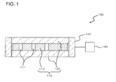
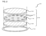
- the electro-acoustic transducer 100 which is an oscillator device of the embodiment will be described with reference to FIGS. 1 and 2 .
- the electro-acoustic transducer 100 of the embodiment includes a piezoelectric vibrator 130 and a supporting member 140.
- the piezoelectric vibrator 130 includes an elastic member 110 and a piezoelectric film 120.
- the elastic member 110 includes a plurality of holes 111.
- the holes 111 vertically penetrate the elastic member 110.
- the piezoelectric film 120 is disposed on one surface of the elastic member 110, and moves expansively and contractively through the application of an electric field.
- the supporting member 140 supports an outer circumferential portion of the piezoelectric vibrator 130. In the examples illustrated in FIGS. 1 and 2 , the supporting member 140 has a frame shape and supports the whole outer circumference of the elastic member 110.
- the elastic member 110 is, for example, phosphor bronze or stainless steel.
- the thickness of the elastic member 10 is preferably equal to or more than 5 ⁇ m and equal to or less than 1000 ⁇ m.
- the elastic member 110 has a longitudinal elastic modulus, which is an index indicating stiffness, of equal to or more than 1 Gpa and equal to or less than 500 GPa.
- At least one of the holes 111 overlaps with the piezoelectric film 120.
- the piezoelectric film 120 covers substantially the entire surface of the elastic member 110.
- all the holes 111 overlap with the piezoelectric film 120.
- the stiffness impedance of the elastic member 110 with respect to the piezoelectric film 120 is adjusted according to the sizes, number, and positions of the holes 111.
- the diameter of the hole 111 is determined in response to various conditions.
- a ratio of the total areas of the holes 111 to an area of a principal surface of the elastic member 110 is also determined in response to various conditions.
- the holes 111 are arranged at equal intervals along the same circular ring.
- the holes 111 are equally dispersed on the entire surface of the elastic member 110, but the holes 111 may be formed so as to be biased to a specific region.
- the elastic member 110 and the piezoelectric film 120 are formed in the form of a disk, and the supporting member 140 is formed in an annular shape.
- the supporting member 140 may be formed in a rectangular shape after the elastic member 110 and the piezoelectric film 120 are formed in a rectangular shape (for example, oblong shape or square shape).
- the piezoelectric film 120 is disposed on both surfaces of the elastic member 110.
- An electrode layer (not shown) is also formed on both surfaces of the piezoelectric film 120, and thus the piezoelectric vibrator 130 is constituted by the electrode layer, the piezoelectric films 120, and the elastic member 110.
- the piezoelectric film 120 is formed of, for example, a polyvinylidene fluoride (PVDF) resin.
- PVDF polyvinylidene fluoride
- a material of the electrode layer formed in the piezoelectric film 120 is not particularly limited, the material is, for example, silver or silver/palladium. Since silver is used as a low-resistance versatile electrode material, there is an advantage in a manufacturing process or cost and the like. Since silver/palladium is a low-resistance material excellent in oxidation resistance, there is an advantage from the viewpoint of reliability.
- the thickness of the electrode layer is not particularly limited, the thickness is preferably 1 ⁇ m to 100 ⁇ m. In the thickness of less than 1 ⁇ m, since a film thickness is thin, it is difficult to uniformly form the electrode layer, and thus there is a possibility of the conversion efficiency decreasing. In addition, when the thickness of the electrode layer exceeds 100 ⁇ m, there is no particular manufacturing problem, but the electrode layer serves as a constraint surface with respect to the piezoelectric film 120, and thus there is a possibility of the energy conversion efficiency being caused to decrease.
- a driver circuit 150 which is an oscillation driving unit is connected to the piezoelectric vibrator 130.
- the driver circuit 150 causes the piezoelectric vibrator 130 to output sound waves by inputting an oscillation signal.
- the oscillation signal has the same frequency as a fundamental resonance frequency of the piezoelectric vibrator 130.
- a signal is input to the piezoelectric film 120 of the piezoelectric vibrator 130, an expansion and contraction motion occurs in the piezoelectric film 120 and the elastic member 110. Sound waves are generated by the expansion and contraction vibration.
- the piezoelectric vibrator 130 oscillates ultrasonic waves.
- the frequency of the ultrasonic waves is, for example, 20 kHz or more.
- the fundamental resonance frequency of the piezoelectric vibrator 130 is influenced by the shape and size of the piezoelectric film 120. It is preferable that the size of the piezoelectric film 120 be reduced in order to adjust a resonance frequency in a high frequency band, for example, an ultrasonic wave band. Thus, it is likely to reduce the size of the electro-acoustic transducer 100.
- the driver circuit 150 causes the piezoelectric film 120 to oscillate ultrasonic waves on which, for example, FM (Frequency Modulation) or AM (Amplitude Modulation) is performed.
- the ultrasonic waves are demodulated into audible sounds through a non-linear state (sparse and dense state) of air.
- the plurality of holes 111 are formed in the elastic member 110.
- the stiffness impedance with respect to the piezoelectric film 120 can be matched optimally by controlling the number, positions, areas, and the like of the holes 111. Therefore, it is possible to increase a sound pressure level of the sound waves oscillated by the electro-acoustic transducer 100.
- the piezoelectric film 120 is provided on both surfaces of the elastic member 110.
- the piezoelectric vibrator 130 has a bimorph structure, the sound pressure level of the sound waves oscillated by the electro-acoustic transducer 100 further increases.
- the invention is not limited to the embodiment, and allows various modifications thereof without departing from the scope of the invention.
- a bimorph structure has been exemplified in which a respective one of a pair of piezoelectric films 120 is disposed on the both surfaces of the elastic member 110.
- a unimorph structure in which the piezoelectric film 120 is disposed on only a single-sided surface of the elastic member 110.
- the elastic member 110 and the piezoelectric film 120 are formed in the form of a disk, and the supporting member 140 is formed in an annular shape.
- a supporting member 230 may be formed in a rectangular frame shape after the plane surfaces of the elastic member 210 and the piezoelectric film 220 are formed in a rectangular shape, for example, an oblong shape or a square shape.
- holes 211 of the elastic member 210 are formed at positions serving as, for example, grid points.
- the electronic instrument in which the driver circuit 150 which is an oscillation driving unit is connected to the electro-acoustic transducer 100 has been assumed.
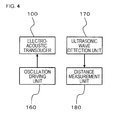
- the electronic instrument may be a sonar including the electro-acoustic transducer 100, an oscillation driving unit 160 that causes the electro-acoustic transducer 100 to output ultrasonic waves, an ultrasonic wave detection unit 170 that detects sound waves (for example, ultrasonic waves reflected by an object to be measured) having the same frequency as the ultrasonic waves oscillated from the electro-acoustic transducer 100, and a distance measurement unit 180 that measures a distance to the object to be measured on the basis of the detected ultrasonic waves.
Landscapes
- Physics & Mathematics (AREA)
- Engineering & Computer Science (AREA)
- Acoustics & Sound (AREA)
- Signal Processing (AREA)
- Transducers For Ultrasonic Waves (AREA)
- Circuit For Audible Band Transducer (AREA)
- Piezo-Electric Transducers For Audible Bands (AREA)
Abstract
Description
- The present invention relates to an oscillator device including a piezoelectric film, and an electronic instrument using the oscillator device.
- In cellular phones, sound functions such as music reproduction or hands-free are required to be enhanced. Accordingly, there is increasing demand for cellular phones that are made small and thin and that has a high-quality sound. As means to respond to the demand, piezoelectric electro-acoustic transducers using a piezoelectric element as an oscillation source have been developed. Since the piezoelectric electro-acoustic transducers use a self-expansion and contraction motion of the piezoelectric element, the piezoelectric electro-acoustic transducers are thinner than electrodynamic electro-acoustic transducers constituted by a magnetic circuit.
- At present, various types of electro-acoustic transducers have been proposed (for example, Patent Document 1).
-
- [Patent Document 1] Japanese Unexamined Patent Publication No.
2006-287480 - Generally, piezoelectric ceramics which are brittle material are used as a piezoelectric element. The piezoelectric ceramics have many problems, such as processing costs and mechanical strength, in order to be used as an audio component for a cellular phone. As means for solving these problems, a piezoelectric film formed of a polymer material is used. Since the piezoelectric film is formed of a resin material rich in flexibility, the piezoelectric film has a high drop impact stability. However, the conversion efficiency of the piezoelectric film is lower than that of piezoelectric ceramics. Thus, in electro-acoustic transducers using the piezoelectric film, a technique to achieve a high sound pressure level is required.
- The invention is contrived in view of such circumstances, and an object of thereof is to provide a piezoelectric oscillator device capable of increasing a sound pressure level while using a piezoelectric film, and an electronic instrument using the oscillator device.
- An oscillator device of the invention includes a piezoelectric vibrator that includes an elastic member having a plurality of through holes and a piezoelectric film that is disposed on one surface of the elastic member and is formed of a polymer material, and a supporting member that supports an outer circumferential portion of the piezoelectric vibrator.
- A first electronic instrument of the invention includes the oscillator device of the invention, and an oscillation driving unit that causes the oscillator device to output ultrasonic waves demodulated into sound waves of an audible zone.
- A second electronic instrument of the invention includes the oscillator device of the invention, an oscillation driving unit that causes the oscillator device to output the ultrasonic waves, an ultrasonic wave detection unit that detects sound waves having the same frequency as the ultrasonic waves, and a distance measurement unit that measures a distance to an object to be measured on the basis of the detected ultrasonic waves.
- According to the oscillator device of the invention, it is possible to increase a sound pressure level while using a piezoelectric film.
- The above-described objects, other objects, features and advantages will be further apparent from the preferred embodiments described below, and the accompanying drawings as follows.
-
-
FIG. 1 is a schematic vertical cross-sectional front view illustrating a structure of an electro-acoustic transducer which is an oscillator device of an embodiment of the invention. -
FIG. 2 is a schematic exploded perspective view illustrating a structure of the electro-acoustic transducer. -
FIG. 3 is a schematic exploded perspective view illustrating a structure of an electro-acoustic transducer according to a modified example. -
FIG. 4 is a diagram illustrating a configuration of an electronic instrument according to a modified example. - Hereinafter, an electro-
acoustic transducer 100 which is an oscillator device of the embodiment will be described with reference toFIGS. 1 and2 . The electro-acoustic transducer 100 of the embodiment includes apiezoelectric vibrator 130 and a supportingmember 140. Thepiezoelectric vibrator 130 includes anelastic member 110 and apiezoelectric film 120. Theelastic member 110 includes a plurality ofholes 111. Theholes 111 vertically penetrate theelastic member 110. Thepiezoelectric film 120 is disposed on one surface of theelastic member 110, and moves expansively and contractively through the application of an electric field. The supportingmember 140 supports an outer circumferential portion of thepiezoelectric vibrator 130. In the examples illustrated inFIGS. 1 and2 , the supportingmember 140 has a frame shape and supports the whole outer circumference of theelastic member 110. - The
elastic member 110 is, for example, phosphor bronze or stainless steel. The thickness of the elastic member 10 is preferably equal to or more than 5 µm and equal to or less than 1000 µm. When the thickness of theelastic member 110 is less than 5 µm, mechanical strength is low, and thus there is a possibility that functions as a constraint member may be damaged. In addition, there is a possibility that variation in machinery vibration characteristics of a vibrator occurs between production lots due to a reduction in processing accuracy. In addition, it is preferable that theelastic member 110 have a longitudinal elastic modulus, which is an index indicating stiffness, of equal to or more than 1 Gpa and equal to or less than 500 GPa. - At least one of the
holes 111 overlaps with thepiezoelectric film 120. For example, in the examples illustrated inFIGS. 1 and2 , thepiezoelectric film 120 covers substantially the entire surface of theelastic member 110. Thus, all theholes 111 overlap with thepiezoelectric film 120. The stiffness impedance of theelastic member 110 with respect to thepiezoelectric film 120 is adjusted according to the sizes, number, and positions of theholes 111. The diameter of thehole 111 is determined in response to various conditions. In addition, a ratio of the total areas of theholes 111 to an area of a principal surface of theelastic member 110 is also determined in response to various conditions. When the plane surface of theelastic member 110 has a circular shape, at least some of theholes 111 are arranged at equal intervals along the same circular ring. For example, theholes 111 are equally dispersed on the entire surface of theelastic member 110, but theholes 111 may be formed so as to be biased to a specific region. - Meanwhile, in the example illustrated in
FIG. 2 , theelastic member 110 and thepiezoelectric film 120 are formed in the form of a disk, and the supportingmember 140 is formed in an annular shape. However, the supportingmember 140 may be formed in a rectangular shape after theelastic member 110 and thepiezoelectric film 120 are formed in a rectangular shape (for example, oblong shape or square shape). - In the
piezoelectric vibrator 130 of the embodiment, thepiezoelectric film 120 is disposed on both surfaces of theelastic member 110. An electrode layer (not shown) is also formed on both surfaces of thepiezoelectric film 120, and thus thepiezoelectric vibrator 130 is constituted by the electrode layer, thepiezoelectric films 120, and theelastic member 110. - The
piezoelectric film 120 is formed of, for example, a polyvinylidene fluoride (PVDF) resin. Although a material of the electrode layer formed in thepiezoelectric film 120 is not particularly limited, the material is, for example, silver or silver/palladium. Since silver is used as a low-resistance versatile electrode material, there is an advantage in a manufacturing process or cost and the like. Since silver/palladium is a low-resistance material excellent in oxidation resistance, there is an advantage from the viewpoint of reliability. - In addition, although the thickness of the electrode layer is not particularly limited, the thickness is preferably 1 µm to 100 µm. In the thickness of less than 1 µm, since a film thickness is thin, it is difficult to uniformly form the electrode layer, and thus there is a possibility of the conversion efficiency decreasing. In addition, when the thickness of the electrode layer exceeds 100 µm, there is no particular manufacturing problem, but the electrode layer serves as a constraint surface with respect to the
piezoelectric film 120, and thus there is a possibility of the energy conversion efficiency being caused to decrease. - A
driver circuit 150 which is an oscillation driving unit is connected to thepiezoelectric vibrator 130. Thedriver circuit 150 causes thepiezoelectric vibrator 130 to output sound waves by inputting an oscillation signal. For example, the oscillation signal has the same frequency as a fundamental resonance frequency of thepiezoelectric vibrator 130. In detail, when a signal is input to thepiezoelectric film 120 of thepiezoelectric vibrator 130, an expansion and contraction motion occurs in thepiezoelectric film 120 and theelastic member 110. Sound waves are generated by the expansion and contraction vibration. When the electro-acoustic transducer 100 is used as a parametric speaker, thepiezoelectric vibrator 130 oscillates ultrasonic waves. The frequency of the ultrasonic waves is, for example, 20 kHz or more. - The fundamental resonance frequency of the
piezoelectric vibrator 130 is influenced by the shape and size of thepiezoelectric film 120. It is preferable that the size of thepiezoelectric film 120 be reduced in order to adjust a resonance frequency in a high frequency band, for example, an ultrasonic wave band. Thus, it is likely to reduce the size of the electro-acoustic transducer 100. - Meanwhile, when the oscillator device functions as a parametric speaker, the
driver circuit 150 causes thepiezoelectric film 120 to oscillate ultrasonic waves on which, for example, FM (Frequency Modulation) or AM (Amplitude Modulation) is performed. The ultrasonic waves are demodulated into audible sounds through a non-linear state (sparse and dense state) of air. - Next, operations and effects of the embodiment will be described. In the electro-
acoustic transducer 100 of the embodiment, the plurality ofholes 111 are formed in theelastic member 110. Thus, the stiffness impedance with respect to thepiezoelectric film 120 can be matched optimally by controlling the number, positions, areas, and the like of theholes 111. Therefore, it is possible to increase a sound pressure level of the sound waves oscillated by the electro-acoustic transducer 100. - In addition, the
piezoelectric film 120 is provided on both surfaces of theelastic member 110. In other words, since thepiezoelectric vibrator 130 has a bimorph structure, the sound pressure level of the sound waves oscillated by the electro-acoustic transducer 100 further increases. - Meanwhile, the invention is not limited to the embodiment, and allows various modifications thereof without departing from the scope of the invention. For example, in the above embodiment, a bimorph structure has been exemplified in which a respective one of a pair of
piezoelectric films 120 is disposed on the both surfaces of theelastic member 110. However, it is also possible to implement a unimorph structure in which thepiezoelectric film 120 is disposed on only a single-sided surface of theelastic member 110. - In addition, in the above embodiment, as illustrated in
FIG. 2 , theelastic member 110 and thepiezoelectric film 120 are formed in the form of a disk, and the supportingmember 140 is formed in an annular shape. However, like an electro-acoustic transducer 200 illustrated inFIG. 3 as the oscillator device, a supportingmember 230 may be formed in a rectangular frame shape after the plane surfaces of theelastic member 210 and thepiezoelectric film 220 are formed in a rectangular shape, for example, an oblong shape or a square shape. In the electro-acoustic transducer 200,holes 211 of theelastic member 210 are formed at positions serving as, for example, grid points. - Further, in the above embodiment, the electronic instrument in which the
driver circuit 150 which is an oscillation driving unit is connected to the electro-acoustic transducer 100 has been assumed. However, as illustrated inFIG. 4 , the electronic instrument may be a sonar including the electro-acoustic transducer 100, anoscillation driving unit 160 that causes the electro-acoustic transducer 100 to output ultrasonic waves, an ultrasonicwave detection unit 170 that detects sound waves (for example, ultrasonic waves reflected by an object to be measured) having the same frequency as the ultrasonic waves oscillated from the electro-acoustic transducer 100, and adistance measurement unit 180 that measures a distance to the object to be measured on the basis of the detected ultrasonic waves. - Meanwhile, as a matter of course, the above-described embodiments and the above-described modified examples can be combined within a range in which contents thereof do not conflict with each other. Additionally, in the above-described embodiments and the above-described modified examples, structures and the like of components have been described in detail, but the structures can be changed in various ways within a range satisfying the invention.
- The application claims the priority based on Japanese Patent Application No.
2010-282674 filed on December 20, 2010
Claims (7)
- An oscillator device comprising:a piezoelectric vibrator that includes an elastic member having a plurality of through holes, and a piezoelectric film that is disposed on one surface of the elastic member and is formed of a polymer material; anda supporting member that supports an outer circumferential portion of the piezoelectric vibrator.
- The oscillator device according to claim 1, wherein the piezoelectric film is disposed on each of both surfaces of the elastic member.
- The oscillator device according to claim 1 or 2, wherein the elastic member is formed of a metal.
- The oscillator device according to any one of claims 1 to 3, wherein the stiffness impedance of the elastic member with respect to the piezoelectric film is adjusted by the formed holes.
- The oscillator device according to any one of claims 1 to 4, wherein at least one of the through holes overlaps with the piezoelectric film.
- An electronic instrument comprising:the oscillator device according to any one of claims 1 to 5; andan oscillation driving unit that causes the oscillator device to output ultrasonic waves demodulated into sound waves of an audible zone.
- An electronic instrument comprising:the oscillator device according to any one of claims 1 to 5;an oscillation driving unit that causes the oscillator device to output the ultrasonic waves;an ultrasonic wave detection unit that detects sound waves having the same frequency as the ultrasonic waves; anda distance measurement unit that measures a distance to an object to be measured on the basis of the detected ultrasonic waves.
Applications Claiming Priority (2)
| Application Number | Priority Date | Filing Date | Title |
|---|---|---|---|
| JP2010282674 | 2010-12-20 | ||
| PCT/JP2011/006521 WO2012086125A1 (en) | 2010-12-20 | 2011-11-24 | Oscillator device and electronic instrument |
Publications (2)
| Publication Number | Publication Date |
|---|---|
| EP2658283A1 true EP2658283A1 (en) | 2013-10-30 |
| EP2658283A4 EP2658283A4 (en) | 2014-06-18 |
Family
ID=46313420
Family Applications (1)
| Application Number | Title | Priority Date | Filing Date |
|---|---|---|---|
| EP11851270.6A Withdrawn EP2658283A4 (en) | 2010-12-20 | 2011-11-24 | Oscillator device and electronic instrument |
Country Status (5)
| Country | Link |
|---|---|
| US (1) | US20130257551A1 (en) |
| EP (1) | EP2658283A4 (en) |
| JP (1) | JP6107138B2 (en) |
| CN (1) | CN103262575B (en) |
| WO (1) | WO2012086125A1 (en) |
Families Citing this family (6)
| Publication number | Priority date | Publication date | Assignee | Title |
|---|---|---|---|---|
| EP2568720A4 (en) * | 2010-07-23 | 2013-11-06 | Nec Corp | Vibration device and electronic device |
| CN103701361A (en) * | 2013-12-19 | 2014-04-02 | 北京京东方光电科技有限公司 | Mobile communication terminal |
| US9378714B1 (en) * | 2015-02-10 | 2016-06-28 | Kevin L. Baldwin, Sr. | Electronic drum |
| TWI644575B (en) * | 2017-06-23 | 2018-12-11 | 英屬開曼群島商智動全球股份有限公司 | Electro-acoustic transducer |
| JP2021190932A (en) * | 2020-06-03 | 2021-12-13 | セイコーエプソン株式会社 | Vibrator and oscillator |
| JP7777752B2 (en) * | 2021-10-01 | 2025-12-01 | パナソニックIpマネジメント株式会社 | Vibration transmission member, and vibration transducer, measuring instrument, and concentration meter using the same |
Family Cites Families (21)
| Publication number | Priority date | Publication date | Assignee | Title |
|---|---|---|---|---|
| JPS4829420A (en) * | 1971-08-20 | 1973-04-19 | ||
| GB1515287A (en) * | 1974-05-30 | 1978-06-21 | Plessey Co Ltd | Piezoelectric transducers |
| JPS553759Y2 (en) * | 1976-04-30 | 1980-01-29 | ||
| JPS5919680B2 (en) * | 1979-02-02 | 1984-05-08 | 呉羽化学工業株式会社 | Variable curvature sound wave transmitter/receiver |
| JPH06275884A (en) * | 1993-03-19 | 1994-09-30 | Casio Comput Co Ltd | Piezoelectric element |
| JPH0715798A (en) * | 1993-06-21 | 1995-01-17 | Matsushita Electric Ind Co Ltd | Piezoelectric electroacoustic transducer |
| WO1998035529A2 (en) * | 1997-02-07 | 1998-08-13 | Sri International | Elastomeric dielectric polymer film sonic actuator |
| US6775388B1 (en) * | 1998-07-16 | 2004-08-10 | Massachusetts Institute Of Technology | Ultrasonic transducers |
| JP2000050387A (en) * | 1998-07-16 | 2000-02-18 | Massachusetts Inst Of Technol <Mit> | Parametric audio system |
| US6321428B1 (en) * | 2000-03-28 | 2001-11-27 | Measurement Specialties, Inc. | Method of making a piezoelectric transducer having protuberances for transmitting acoustic energy |
| JP2004023436A (en) * | 2002-06-17 | 2004-01-22 | Nihon Ceratec Co Ltd | Piezoelectric loudspeaker |
| US6924584B2 (en) * | 2002-12-13 | 2005-08-02 | Palo Alto Research Center Inc. | Piezoelectric transducers utilizing sub-diaphragms |
| JP2005286690A (en) * | 2004-03-30 | 2005-10-13 | Mitsubishi Electric Engineering Co Ltd | Piezoelectric film speaker and parametric speaker employing the same |
| JP2006287480A (en) * | 2005-03-31 | 2006-10-19 | Taiyo Yuden Co Ltd | Piezoelectric laminate, manufacturing method, piezoelectric speaker, and electronic apparatus |
| KR100642913B1 (en) * | 2005-10-29 | 2006-11-10 | 드림 소닉 테크놀러지 리미티드 | Low bass reinforcement thin speaker using piezoelectric film as vibrating element |
| JP2007300426A (en) * | 2006-04-28 | 2007-11-15 | Sony Corp | Piezoelectric vibrator and piezoelectric vibration generator provided with the same |
| JP2007329431A (en) * | 2006-06-09 | 2007-12-20 | Citizen Electronics Co Ltd | Piezoelectric exciter |
| JP2008279912A (en) * | 2007-05-11 | 2008-11-20 | Bosch Corp | Object detection device for vehicle |
| CN201314953Y (en) * | 2008-09-27 | 2009-09-23 | 北京竞业达数字系统科技有限公司 | Ultrasonic ranging system |
| CN102460938B (en) * | 2009-05-11 | 2015-04-01 | 日本电气株式会社 | Piezo Actuators and Audio Components |
| JP2010282674A (en) | 2009-06-02 | 2010-12-16 | Hitachi Ltd | Magnetic disk medium and magnetic disk device |
-
2011
- 2011-11-24 JP JP2012549608A patent/JP6107138B2/en not_active Expired - Fee Related
- 2011-11-24 US US13/991,210 patent/US20130257551A1/en not_active Abandoned
- 2011-11-24 WO PCT/JP2011/006521 patent/WO2012086125A1/en not_active Ceased
- 2011-11-24 CN CN201180061413.5A patent/CN103262575B/en not_active Expired - Fee Related
- 2011-11-24 EP EP11851270.6A patent/EP2658283A4/en not_active Withdrawn
Also Published As
| Publication number | Publication date |
|---|---|
| EP2658283A4 (en) | 2014-06-18 |
| JPWO2012086125A1 (en) | 2014-05-22 |
| JP6107138B2 (en) | 2017-04-05 |
| CN103262575A (en) | 2013-08-21 |
| US20130257551A1 (en) | 2013-10-03 |
| WO2012086125A1 (en) | 2012-06-28 |
| CN103262575B (en) | 2017-05-31 |
Similar Documents
| Publication | Publication Date | Title |
|---|---|---|
| US8891333B2 (en) | Oscillator and electronic device | |
| US9179214B2 (en) | Audio equipment and oscillation unit | |
| US9337773B2 (en) | Oscillation device and electronic apparatus | |
| JP5682973B2 (en) | Oscillator and electronic device | |
| US9306148B2 (en) | Oscillator device and electronic apparatus | |
| US20130257551A1 (en) | Oscillator device and electronic instrument | |
| CN102959992B (en) | Agitator and electronic equipment | |
| JP2012015758A (en) | Oscillator, method for manufacturing the same and electronic device | |
| JP2012015755A (en) | Oscillation device and electronic equipment | |
| JP6156387B2 (en) | Electroacoustic transducer, manufacturing method thereof, and electronic apparatus using the electroacoustic transducer | |
| JP2012134597A (en) | Oscillation device and electronic apparatus | |
| JP2012134596A (en) | Oscillation device and electronic apparatus | |
| JP2012134595A (en) | Oscillation device and electronic apparatus | |
| JP5505165B2 (en) | Oscillator | |
| JP2012029104A (en) | Oscillator and electronic apparatus | |
| JP2012134599A (en) | Oscillation device and electronic apparatus | |
| JP2012134593A (en) | Oscillation device and electronic apparatus | |
| JP2012134594A (en) | Oscillation device and electronic apparatus | |
| JP2012134598A (en) | Oscillator and electronic apparatus | |
| JP2012015756A (en) | Electronic apparatus and oscillation unit | |
| JPWO2014097863A1 (en) | SOUND GENERATOR, SOUND GENERATOR, AND ELECTRONIC DEVICE |
Legal Events
| Date | Code | Title | Description |
|---|---|---|---|
| PUAI | Public reference made under article 153(3) epc to a published international application that has entered the european phase |
Free format text: ORIGINAL CODE: 0009012 |
|
| 17P | Request for examination filed |
Effective date: 20130620 |
|
| AK | Designated contracting states |
Kind code of ref document: A1 Designated state(s): AL AT BE BG CH CY CZ DE DK EE ES FI FR GB GR HR HU IE IS IT LI LT LU LV MC MK MT NL NO PL PT RO RS SE SI SK SM TR |
|
| DAX | Request for extension of the european patent (deleted) | ||
| A4 | Supplementary search report drawn up and despatched |
Effective date: 20140516 |
|
| RIC1 | Information provided on ipc code assigned before grant |
Ipc: H04R 3/00 20060101ALI20140512BHEP Ipc: G01S 7/521 20060101ALI20140512BHEP Ipc: G01S 15/08 20060101ALI20140512BHEP Ipc: H04R 17/00 20060101AFI20140512BHEP |
|
| RAP1 | Party data changed (applicant data changed or rights of an application transferred) |
Owner name: NEC CORPORATION |
|
| 17Q | First examination report despatched |
Effective date: 20160707 |
|
| STAA | Information on the status of an ep patent application or granted ep patent |
Free format text: STATUS: THE APPLICATION IS DEEMED TO BE WITHDRAWN |
|
| 18D | Application deemed to be withdrawn |
Effective date: 20180306 |