EP2658224A2 - Terminal apparatus, backlight control method, and backlight control program - Google Patents
Terminal apparatus, backlight control method, and backlight control program Download PDFInfo
- Publication number
- EP2658224A2 EP2658224A2 EP13163761.3A EP13163761A EP2658224A2 EP 2658224 A2 EP2658224 A2 EP 2658224A2 EP 13163761 A EP13163761 A EP 13163761A EP 2658224 A2 EP2658224 A2 EP 2658224A2
- Authority
- EP
- European Patent Office
- Prior art keywords
- terminal apparatus
- determination unit
- proximity
- holding
- backlight
- Prior art date
- Legal status (The legal status is an assumption and is not a legal conclusion. Google has not performed a legal analysis and makes no representation as to the accuracy of the status listed.)
- Granted
Links
Images





Classifications
-
- H—ELECTRICITY
- H04—ELECTRIC COMMUNICATION TECHNIQUE
- H04M—TELEPHONIC COMMUNICATION
- H04M1/00—Substation equipment, e.g. for use by subscribers
- H04M1/02—Constructional features of telephone sets
- H04M1/22—Illumination; Arrangements for improving the visibility of characters on dials
-
- H—ELECTRICITY
- H04—ELECTRIC COMMUNICATION TECHNIQUE
- H04W—WIRELESS COMMUNICATION NETWORKS
- H04W52/00—Power management, e.g. Transmission Power Control [TPC] or power classes
- H04W52/02—Power saving arrangements
- H04W52/0209—Power saving arrangements in terminal devices
- H04W52/0251—Power saving arrangements in terminal devices using monitoring of local events, e.g. events related to user activity
- H04W52/0254—Power saving arrangements in terminal devices using monitoring of local events, e.g. events related to user activity detecting a user operation or a tactile contact or a motion of the device
-
- H—ELECTRICITY
- H04—ELECTRIC COMMUNICATION TECHNIQUE
- H04W—WIRELESS COMMUNICATION NETWORKS
- H04W52/00—Power management, e.g. Transmission Power Control [TPC] or power classes
- H04W52/02—Power saving arrangements
- H04W52/0209—Power saving arrangements in terminal devices
- H04W52/0261—Power saving arrangements in terminal devices managing power supply demand, e.g. depending on battery level
- H04W52/0267—Power saving arrangements in terminal devices managing power supply demand, e.g. depending on battery level by controlling user interface components
- H04W52/027—Power saving arrangements in terminal devices managing power supply demand, e.g. depending on battery level by controlling user interface components by controlling a display operation or backlight unit
-
- H—ELECTRICITY
- H05—ELECTRIC TECHNIQUES NOT OTHERWISE PROVIDED FOR
- H05B—ELECTRIC HEATING; ELECTRIC LIGHT SOURCES NOT OTHERWISE PROVIDED FOR; CIRCUIT ARRANGEMENTS FOR ELECTRIC LIGHT SOURCES, IN GENERAL
- H05B47/00—Circuit arrangements for operating light sources in general, i.e. where the type of light source is not relevant
- H05B47/10—Controlling the light source
- H05B47/105—Controlling the light source in response to determined parameters
- H05B47/115—Controlling the light source in response to determined parameters by determining the presence or movement of objects or living beings
-
- H—ELECTRICITY
- H04—ELECTRIC COMMUNICATION TECHNIQUE
- H04M—TELEPHONIC COMMUNICATION
- H04M2250/00—Details of telephonic subscriber devices
- H04M2250/12—Details of telephonic subscriber devices including a sensor for measuring a physical value, e.g. temperature or motion
-
- H—ELECTRICITY
- H04—ELECTRIC COMMUNICATION TECHNIQUE
- H04M—TELEPHONIC COMMUNICATION
- H04M2250/00—Details of telephonic subscriber devices
- H04M2250/52—Details of telephonic subscriber devices including functional features of a camera
-
- H—ELECTRICITY
- H05—ELECTRIC TECHNIQUES NOT OTHERWISE PROVIDED FOR
- H05B—ELECTRIC HEATING; ELECTRIC LIGHT SOURCES NOT OTHERWISE PROVIDED FOR; CIRCUIT ARRANGEMENTS FOR ELECTRIC LIGHT SOURCES, IN GENERAL
- H05B47/00—Circuit arrangements for operating light sources in general, i.e. where the type of light source is not relevant
- H05B47/10—Controlling the light source
- H05B47/105—Controlling the light source in response to determined parameters
- H05B47/115—Controlling the light source in response to determined parameters by determining the presence or movement of objects or living beings
- H05B47/125—Controlling the light source in response to determined parameters by determining the presence or movement of objects or living beings by using cameras
-
- Y—GENERAL TAGGING OF NEW TECHNOLOGICAL DEVELOPMENTS; GENERAL TAGGING OF CROSS-SECTIONAL TECHNOLOGIES SPANNING OVER SEVERAL SECTIONS OF THE IPC; TECHNICAL SUBJECTS COVERED BY FORMER USPC CROSS-REFERENCE ART COLLECTIONS [XRACs] AND DIGESTS
- Y02—TECHNOLOGIES OR APPLICATIONS FOR MITIGATION OR ADAPTATION AGAINST CLIMATE CHANGE
- Y02B—CLIMATE CHANGE MITIGATION TECHNOLOGIES RELATED TO BUILDINGS, e.g. HOUSING, HOUSE APPLIANCES OR RELATED END-USER APPLICATIONS
- Y02B20/00—Energy efficient lighting technologies, e.g. halogen lamps or gas discharge lamps
- Y02B20/40—Control techniques providing energy savings, e.g. smart controller or presence detection
-
- Y—GENERAL TAGGING OF NEW TECHNOLOGICAL DEVELOPMENTS; GENERAL TAGGING OF CROSS-SECTIONAL TECHNOLOGIES SPANNING OVER SEVERAL SECTIONS OF THE IPC; TECHNICAL SUBJECTS COVERED BY FORMER USPC CROSS-REFERENCE ART COLLECTIONS [XRACs] AND DIGESTS
- Y02—TECHNOLOGIES OR APPLICATIONS FOR MITIGATION OR ADAPTATION AGAINST CLIMATE CHANGE
- Y02D—CLIMATE CHANGE MITIGATION TECHNOLOGIES IN INFORMATION AND COMMUNICATION TECHNOLOGIES [ICT], I.E. INFORMATION AND COMMUNICATION TECHNOLOGIES AIMING AT THE REDUCTION OF THEIR OWN ENERGY USE
- Y02D30/00—Reducing energy consumption in communication networks
- Y02D30/70—Reducing energy consumption in communication networks in wireless communication networks
Definitions
- the embodiments discussed herein are related to a terminal apparatus, a backlight control method, and a backlight control program that are capable of controlling a backlight of a display.
- a function of setting a lighting time period of a backlight in advance is implemented.
- this function when this function is used, in such a terminal apparatus, for example, when the lighting time period is set to be short, the backlight is automatically turned off although a user is looking at a display.
- the lighting time period when the lighting time period is set to be long, in the terminal apparatus, the backlight is continuously turned on although the user is not looking at the display. Accordingly, the power is wastefully consumed.
- a terminal apparatus in which a function of turning on and off the backlight in accordance with an inclination obtained using an acceleration sensor is implemented. By using this function, performing control so that the backlight of the display is not turned off when the user is holding the terminal apparatus in his or her hand and looking at the display is made possible.
- Japanese Laid-open Patent Publication No. 2011-142497 is an example of the related art.
- the disclosed embodiments aim to provide a terminal apparatus, a backlight control method, and a backlight control program that are capable of efficiently reducing the power consumption even though accidental turning off of the backlight is avoided.
- a terminal apparatus includes a display device; a first sensor configured to detect a proximity state of being in proximity to an object different from the terminal apparatus; a second sensor configured to detect vibrations; and a processor, wherein the processor determines whether or not a first detection value acquired from the first sensor indicates that the terminal apparatus is in the proximity state, turns off a backlight of the display device in accordance with the first detection value, and acquires, when it is determined that the first detection value does not indicate that the terminal apparatus is in the proximity state, a second detection value from the second sensor, determines whether or not the second detection value, which has been acquired, indicates that the terminal apparatus is vibrating, and turns off the backlight of the display device in accordance with the second detection value.
- FIG. 1 is a diagram illustrating an example of a hardware configuration of a terminal apparatus according to a present embodiment.
- a terminal apparatus 1 includes a processor 11 that is a central processing unit (CPU) or a field programmable gate array (FPGA).
- the terminal apparatus 1 further includes a microcomputer 12 that controls various types of sensors, such as an acceleration sensor 13 and a proximity sensor 14, and a storage section 15 that includes various types of memories, such as a read only memory (ROM) 16 and a random access memory (RAM) 17.
- ROM read only memory
- RAM random access memory
- the terminal apparatus 1 further includes a timer section 18, a display section 19, a key input section 20, a camera 21, a voice input and output section 22 that controls a speaker and a microphone, and a wireless section 23 that performs transmission and reception of a signal via an antenna.
- the processor 11 is connected to various types of hardware included in the terminal apparatus 1. Accordingly, the processor 11 controls overall control of the apparatus, and executes, for example, a backlight control program according to the present embodiment.
- a backlight control program for example, various types of programs, such as the backlight control program according to the present embodiment, are stored.
- the RAM 17 for example, data that is obtained in the course of a process is stored.
- the processor 11 reads the backlight control program according to the present embodiment from the ROM 16, and performs control of a backlight.
- the timer section 18 includes multiple timers, and is controlled by the processor 11 so as to cause each of the timers to start and stop counting.
- the microcomputer 12 detects, using the acceleration sensor 13, an inclination and vibrations of the terminal apparatus 1.
- the acceleration sensor 13 may be a gyro sensor.
- the terminal apparatus 1 may include both an acceleration sensor and a gyro sensor so as to function as a sensor that detects an inclination and vibrations. Additionally, when the acceleration sensor 13 is driven, a current of about 200 ⁇ A is consumed.
- the acceleration sensor 13 is used as a sensor that detects an inclination and vibrations will be described.
- the microcomputer 12 detects, using the proximity sensor 14, whether an object is in proximity to the terminal apparatus 1.
- Examples of the proximity sensor 14 include an optical sensor, an infrared sensor, and an ultrasonic sensor. When the proximity sensor 14 is driven, a current of about 3 ⁇ A is consumed.
- the microcomputer 12 and the processor 11 are individually disposed in the present embodiment, the disposition of the microcomputer 12 and the processor 11 is not limited thereto.
- the microcomputer 12 and the processor 11 may be formed as one piece.
- the display section 19 is a display, and is controlled by the processor 11 so as to perform a process of displaying a screen.
- the key input section 20 is an operation keypad or the like.
- the camera 21 is controlled by the processor 11 so as to be capable of capturing a moving image and a still image.
- the voice input and output section 22 is controlled by the processor 11 so as to perform a process of outputting a voice to the speaker and a process of inputting a voice from the microphone.
- the wireless section 23 is controlled by the processor 11 so as to transmit and receive voice-call data or the like via the antenna.
- the terminal apparatus 1 is capable of operating as a mobile information terminal such as a mobile phone, a smartphone, a PDA, or a mobile PC.
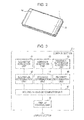
- FIG. 2 is a perspective view of the terminal apparatus 1.
- the terminal apparatus 1 according to the present embodiment is configured so that the proximity sensor 14 is able to emit light, such as infrared light, so as to cause the light to travel from a hole, which is provided in a housing, to the outside of the housing, and is able to receive reflected light of the light.
- light such as infrared light
- FIG. 3 is a diagram illustrating an example of a functional block configuration of the terminal apparatus according to the present embodiment.
- the processor 11 executes the backlight control program according to the first embodiment, thereby operating as a control section 31A.
- the control section 31A includes an inclination acquisition unit 41, an inclination determination unit 42, a vibration acquisition unit 43, a stillness determination unit 44, a proximity-information acquisition unit 45, a proximity determination unit 46, a holding-in-hand determination unit 47, and a display control unit 48.
- the inclination acquisition unit 41 acquires a value indicating an inclination of the terminal apparatus 1, which has been detected by the microcomputer 12 using the acceleration sensor 13.
- the inclination determination unit 42 smoothes the value indicating an inclination, which has been obtained from the inclination acquisition unit 41, and determines whether the terminal apparatus 1 is inclined. For example, a reference value that is used to determine whether the terminal apparatus 1 is inclined is provided, and the inclination determination unit 42 determines, using this reference value, whether the terminal apparatus 1 is inclined. Note that the reference value may be appropriately changed by a user.
- the vibration acquisition unit 43 acquires a value indicating vibrations of the terminal apparatus 1, which have been detected by the microcomputer 12 using the acceleration sensor 13.
- the stillness determination unit 44 smoothes the value indicating vibrations, which has been obtained from the vibration acquisition unit 43, and determines whether the terminal apparatus 1 is still. For example, a reference value that is used to determine whether the terminal apparatus 1 is still without vibrating is provided, and the stillness determination unit 44 determines, using this reference value, whether the terminal apparatus 1 is still. Note that the reference value may be appropriately changed by the user.
- the proximity-information acquisition unit 45 acquires proximity information that has been detected by the microcomputer 12 using the proximity sensor 14, that is, information indicating whether the terminal apparatus 1 is in proximity to a certain object.
- the proximity determination unit 46 determines, based on the proximity information obtained from the proximity-information acquisition unit 45, whether the terminal apparatus 1 is in proximity to a certain object.
- the holding-in-hand determination unit 47 determines, based on at least any one of results of determination performed by the inclination determination unit 42, the stillness determination unit 44, and the proximity determination unit 46, whether the user is holding the terminal apparatus 1 in his or her hand. Then, the holding-in-hand determination unit 47 instructs the display control unit 48 to set and cancel a continuous lighting state.
- the display control unit 48 performs control so that the backlight of the display section 19 is turned on and turned off. Furthermore, the display control unit 48 displays an icon on the screen or turns on a light emitting diode (LED), thereby notifying the user that the backlight is in the continuous lighting state.
- LED light emitting diode
- FIG. 4 is a flowchart illustrating a process performed by the control section 31A.
- the control section 31A operates so that the backlight enters, using turning on of the backlight as a trigger, the continuous lighting state. In this state, the control section 31A starts performing control of the backlight in the present embodiment.
- a lighting time period is set in advance by the above-described "function of setting the lighting time period of the backlight in advance".
- the holding-in-hand determination unit 47 of the control section 31A transmits, using turning on of the backlight as a trigger, to the microcomputer 12, an instruction to turn on the proximity sensor 14 (step S1).
- the proximity-information acquisition unit 45 transfers, to the proximity determination unit 46, the proximity information transmitted from the microcomputer 12.
- the proximity determination unit 46 determines, based on the proximity information transferred from the proximity-information acquisition unit 45, whether the terminal apparatus 1 is in proximity to a certain object (step S2).
- the proximity determination unit 46 determines that the terminal apparatus 1 is not in proximity to any object (NO in step S2)
- the proximity determination unit 46 notifies the holding-in-hand determination unit 47 of information indicating that the terminal apparatus 1 is not in proximity to any object.
- the proximity determination unit 46 resets the proximity timer, thereby causing the proximity timer to stop counting (step S3).
- the holding-in-hand determination unit 47 which has been notified of the information indicating that the terminal apparatus 1 is not in proximity to any object, transmits, to the microcomputer 12, an instruction to turn on the acceleration sensor 13 that serves as an inclination sensor (step S4). Note that, when the acceleration sensor 13 has already been turned on, the process of step S4 is skipped.
- step S2 when the proximity determination unit 46 determines that the terminal apparatus 1 is in proximity to a certain object (YES in S2), the proximity determination unit 46 starts the proximity timer included in the timer section 18 (step S5). Note that, when the proximity timer has already started counting, the process of step S5 is skipped. Then, the holding-in-hand determination unit 47 determines whether the proximity timer has expired (step S6). When the holding-in-hand determination unit 47 determines that the proximity timer has not expired (NO in step S6), the holding-in-hand determination unit 47 transmits, to the microcomputer 12, an instruction to turn on the acceleration sensor 13 that serves as an inclination sensor (step S4). Note that, when the acceleration sensor 13 has already been turned on, the process of step S4 is skipped.
- the inclination acquisition unit 41 transfers, to the inclination determination unit 42, a value that indicates an inclination and that is periodically transmitted from the microcomputer 12.
- the inclination determination unit 42 smoothes the value indicating an inclination, which has been transferred from the inclination acquisition unit 41, and determines, using the smoothed value, whether the terminal apparatus 1 is inclined (step S7). For example, when the inclination determination unit 42 determines that the terminal apparatus 1 is inclined (YES in step S7), the inclination determination unit 42 notifies the holding-in-hand determination unit 47 of information indicating that the terminal apparatus 1 is inclined.
- step S8 the holding-in-hand determination unit 47, which has been notified of the information indicating that the terminal apparatus 1 is inclined, transmits, to the microcomputer 12, an instruction to turn on the acceleration sensor 13 that serves as a vibration sensor (step S8).
- the acceleration sensor 13 has already been turned on, the process of step S8 is skipped.
- the vibration acquisition unit 43 transfers, to the stillness determination unit 44, a value that indicates vibrations and that is periodically transmitted from the microcomputer 12.
- the stillness determination unit 44 smoothes the value indicating vibrations, which has been transferred from the vibration acquisition unit 43, and determines, using the smoothed value, whether the terminal apparatus 1 is vibrating, that is, whether the terminal apparatus 1 is shaking (step S9).
- the stillness determination unit 44 determines that the terminal apparatus 1 is vibrating (YES in step S9)
- the stillness determination unit 44 notifies the holding-in-hand determination unit 47 of information indicating that the terminal apparatus 1 is vibrating.
- the stillness determination unit 44 resets the stillness timer, thereby causing the stillness timer to stop counting (step S10).
- the holding-in-hand determination unit 47 which has been notified of the information indicating that the terminal apparatus 1 is vibrating, instructs the display control unit 48 to maintain the continuous lighting state (step S11).
- step S9 when the stillness determination unit 44 determines that the terminal apparatus 1 is not vibrating (NO in step S9), the stillness determination unit 44 starts the stillness timer included in the timer section 18 (step S12). Note that, when the stillness timer has already started counting, the process of step S12 is skipped. Then, the holding-in-hand determination unit 47 determines whether the stillness timer has expired (step S13). When the holding-in-hand determination unit 47 determines that the stillness timer has not expired (NO in step S13), the holding-in-hand determination unit 47 instructs the display control unit 48 to maintain the continuous lighting state (step S11).
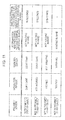
- FIG. 5 is a table listing conditions under which determination of whether the user is holding the terminal apparatus 1 in his or her hand is performed, and time periods taken to determine that the user is not holding the terminal apparatus 1 in his or her hand. For example, the above-mentioned case in which the holding-in-hand determination unit 47 determines that the user is holding the terminal apparatus 1 in his or her hand corresponds to the first case from the bottom in FIG. 5 .
- the holding-in-hand determination unit 47 determines that the proximity determination unit 46 is determining whether the terminal apparatus 1 has been in proximity to a certain object for a fixed time period, and instructs the display control unit 48 to maintain the continuous lighting state (step S11).
- the fixed time period is a time period indicating the expiry of the proximity timer.
- the fixed time period is, for example, 10 seconds.
- the holding-in-hand determination unit 47 determines that the stillness determination unit 44 is determining whether the terminal apparatus 1 has remained still for a fixed time period, and instructs the display control unit 48 to maintain the continuous lighting state (step S11).
- the fixed time period is a time period indicating the expiry of the stillness timer.
- the fixed time period is, for example, 60 seconds.
- step S7 when the inclination determination unit 42 determines that the terminal apparatus 1 is not inclined (NO in step S7), the inclination determination unit 42 notifies the holding-in-hand determination unit 47 of information indicating that the terminal apparatus 1 is not inclined.
- the holding-in-hand determination unit 47 which has been notified of the information indicating that the terminal apparatus 1 is not inclined, determines that the user is not holding the terminal apparatus 1 in his or her hand. This case corresponds to the first case from the top in FIG. 5 . In other words, the holding-in-hand determination unit 47 may determine that the user is not holding the terminal apparatus 1 in his or her hand immediately after the inclination sensor has been turned on.
- the holding-in-hand determination unit 47 determines that the user is not holding the terminal apparatus 1 in his or her hand. This case corresponds to the second case from the top in FIG. 5 . In other words, at a point in time when 10 seconds, which is the time period indicating the expiry of the proximity timer, have elapsed since the proximity timer started, the holding-in-hand determination unit 47 may determine that the user is not holding the terminal apparatus 1 in his or her hand.
- the holding-in-hand determination unit 47 determines that the user is not holding the terminal apparatus 1 in his or her hand. This case corresponds to the third case from the top in FIG. 5 . In other words, at a point in time when 60 seconds, which is the time period indicating the expiry of the stillness timer, have elapsed since the stillness timer started, the holding-in-hand determination unit 47 may determine that the user is not holding the terminal apparatus 1 in his or her hand.
- the holding-in-hand determination unit 47 which has determined that the user is not holding the terminal apparatus 1 in his or her hand, resets all timers that are counting among the timers included in the timer section 18, thereby causing the timers to stop counting (step S14). Moreover, the holding-in-hand determination unit 47 transmits, to the microcomputer 12, an instruction to turn off all sensors that are operating (step S15). Finally, the holding-in-hand determination unit 47 instructs the display control unit 48 to cancel the continuous lighting state (step S16).
- the display control unit 48 turns off the backlight of the display section 19.
- the holding-in-hand determination unit 47 determines, based on at least any one of results of determination performed by the inclination determination unit 42, the stillness determination unit 44, and the proximity determination unit 46, whether the user is holding the terminal apparatus 1 in his or her hand. Then, the holding-in-hand determination unit 47 determines, based on a result of determination of whether the user is holding the terminal apparatus 1 in his or her hand, whether the continuous lighting state is to be maintained or cancelled. Accordingly, even though accidental turning off of the backlight is avoided, the backlight may be appropriately turned off when the backlight is unnecessary. Thus, the power consumption may be efficiently reduced.
- time periods of 0 seconds, 10 seconds, and 60 seconds which are time periods taken to determine that the user is not holding the terminal apparatus 1 in his or her hand and which are illustrated in FIG. 5 , are examples, and any time periods may be set as the time periods by the user of the terminal apparatus 1.
- the display control unit 48 displays an icon on the screen or turns on an LED, whereby the user may be notified that the backlight is in the continuous lighting state.
- the holding-in-hand determination unit 47 provides, using turning on of the backlight as a trigger, an instruction to display an icon indicating that the backlight is in the continuous lighting state on the screen, and provides an instruction to delete the icon several seconds before any one of the timers expires. Accordingly, the user of the terminal apparatus 1 may recognize that the continuous lighting state is to be cancelled in several seconds. For example, the continuous lighting state may be maintained by inclining, shaking, or moving the terminal apparatus 1.
- the inclination determination unit 42 determines whether the terminal apparatus 1 is inclined (step S7).
- control of the backlight may be performed without performing this process.
- control of the backlight is performed based on results of determination performed by the stillness determination unit 44 and the proximity determination unit 46.
- FIG. 4 becomes a diagram in which steps S4 and S7 are removed, in which steps S3 and S8 are directly connected, and in which steps S6 (NO) and S8 are directly connected.
- the proximity sensor 14 is turned on using as turning on of the backlight as a trigger (step S1).
- this trigger is not limited thereto.
- the holding-in-hand determination unit 47 may start, using turning on of the backlight as a trigger, monitoring the lighting time period. Further, the holding-in-hand determination unit 47 may transmit, using a lapse of the lighting time period as a trigger, to the microcomputer 12, an instruction to turn on the proximity sensor 14 (step S1). In this case, in the process of step S16, the holding-in-hand determination unit 47 instructs the display control unit 48 to turn off the backlight (step S16).
- FIG. 6 is a diagram illustrating an example of a functional block configuration of the terminal apparatus according to the present embodiment.
- the processor 11 illustrated in FIG. 1 executes a backlight control program according to the second embodiment, thereby operating as a control section 31B.
- the control section 31B includes an inclination acquisition unit 41, an inclination determination unit 42B, a vibration acquisition unit 43B, a stillness determination unit 44, a proximity-information acquisition unit 45B, a proximity determination unit 46, a holding-in-hand determination unit 47, and a display control unit 48.
- elements of the control section 31B that are the same as the elements of the control section 31A described above are denoted by the same reference numerals, and a description of the same elements is omitted.
- the inclination determination unit 42B has a function of notifying, in the case where the inclination determination unit 42 determines that the terminal apparatus 1 is inclined, the vibration acquisition unit 43B and the proximity-information acquisition unit 45B that the terminal apparatus 1 is inclined.
- the vibration acquisition unit 43B has received the notification from the inclination determination unit 42B
- the vibration acquisition unit 43B is enabled to acquire a value indicating vibrations of the terminal apparatus 1, which have been detected by the microcomputer 12 using the acceleration sensor 13.
- the proximity-information acquisition unit 45B has received the notification from the inclination determination unit 42B
- the proximity-information acquisition unit 45B is enabled to acquire the proximity information that has been detected by the microcomputer 12 using the proximity sensor 14.
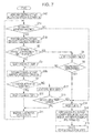
- FIG. 7 is a flowchart illustrating a process performed by the control section 31B.
- the control section 31B operates so that the backlight enters, using turning on of the backlight as a trigger, the continuous lighting state. In this state, the control section 31B starts performing control of the backlight in the present embodiment.
- a lighting time period is set in advance by the above-described "function of setting the lighting time period of the backlight in advance".
- the holding-in-hand determination unit 47 of the control section 31B transmits, using turning on of the backlight as a trigger, to the microcomputer 12, an instruction to turn on the acceleration sensor 13 (step S4B).
- the inclination acquisition unit 41 transfers, to the inclination determination unit 42B, a value that indicates an inclination and that is periodically transmitted from the microcomputer 12.
- the inclination determination unit 42B smoothes the value indicating an inclination, which has been transferred from the inclination acquisition unit 41, and determines, using the smoothed value, whether the terminal apparatus 1 is inclined (step S7B). For example, when the inclination determination unit 42B determines that the terminal apparatus 1 is inclined (YES in step S7B), the inclination determination unit 42 notifies the holding-in-hand determination unit 47, the vibration acquisition unit 43B, and the proximity-information acquisition unit 45B of information indicating that the terminal apparatus 1 is inclined.
- the holding-in-hand determination unit 47 which has been notified of the information indicating that the terminal apparatus 1 is inclined, transmits, to the microcomputer 12, an instruction to turn on the proximity sensor 14 (step S1B).
- the vibration acquisition unit 43B receives, from the inclination determination unit 42B, the information indicating that the terminal apparatus 1 is inclined, whereby the vibration acquisition unit 43B is enabled to acquire the value indicating an inclination.
- the proximity-information acquisition unit 45B receives, from the inclination determination unit 42B, the information indicating that the terminal apparatus 1 is inclined, whereby the proximity-information acquisition unit 45B is enabled to acquire proximity information.
- the proximity-information acquisition unit 45B transfers, to the proximity determination unit 46, the proximity information transmitted from the microcomputer 12.
- the proximity determination unit 46 determines, based on the proximity information transferred from the proximity-information acquisition unit 45B, whether the terminal apparatus 1 is in proximity to a certain object (step S2).
- the proximity determination unit 46 determines that the terminal apparatus 1 is not in proximity to any object (NO in step S2)
- the proximity determination unit 46 notifies the holding-in-hand determination unit 47 of information indicating that the terminal apparatus 1 is not in proximity to any object.
- the proximity determination unit 46 resets the proximity timer, thereby causing the proximity timer to stop counting (step S3).
- the holding-in-hand determination unit 47 which has been notified of the information indicating that the terminal apparatus 1 is not in proximity to any object, transmits, to the microcomputer 12, an instruction to turn on the acceleration sensor 13 that serves as a vibration sensor (step S8B).
- the acceleration sensor 13 has already been turned on, the process of step S8B is skipped.
- step S2 when the proximity determination unit 46 determines that the terminal apparatus 1 is in proximity to a certain object (YES in S2), the proximity determination unit 46 starts the proximity timer included in the timer section 18 (step S5). Note that, when the proximity timer has already started counting, the process of step S5 is skipped. Then, the holding-in-hand determination unit 47 determines whether the proximity timer has expired (step S6). When the holding-in-hand determination unit 47 determines that the proximity timer has not expired (NO in step S6), the holding-in-hand determination unit 47 transmits, to the microcomputer 12, an instruction to turn on the acceleration sensor 13 that serves as a vibration sensor (step S8B). Here, because the acceleration sensor 13 has already been turned on, the process of step S8B is skipped.
- the vibration acquisition unit 43B transfers, to the stillness determination unit 44, a value that indicates vibrations and that is periodically transmitted from the microcomputer 12.
- the stillness determination unit 44 smoothes the value indicating vibrations, which has been transferred from the vibration acquisition unit 43B, and determines, using the smoothed value, whether the terminal apparatus 1 is vibrating, that is, whether the terminal apparatus 1 is shaking (step S9).
- the stillness determination unit 44 determines that the terminal apparatus 1 is vibrating (YES in step S9)
- the stillness determination unit 44 notifies the holding-in-hand determination unit 47 of information indicating that the terminal apparatus 1 is vibrating.
- the stillness determination unit 44 resets the stillness timer, thereby causing the stillness timer to stop counting (step S10).
- the holding-in-hand determination unit 47 which has been notified of the information indicating that the terminal apparatus 1 is vibrating, instructs the display control unit 48 to maintain the continuous lighting state (step S11).
- step S9 when the stillness determination unit 44 determines that the terminal apparatus 1 is not vibrating (NO in step S9), the stillness determination unit 44 starts the stillness timer included in the timer section 18 (step S12). Note that, when the stillness timer has already started counting, the process of step S12 is skipped. Then, the holding-in-hand determination unit 47 determines whether the stillness timer has expired (step S13). When the holding-in-hand determination unit 47 determines that the stillness timer has not expired (NO in step S13), the holding-in-hand determination unit 47 instructs the display control unit 48 to maintain the continuous lighting state (step S11).
- the holding-in-hand determination unit 47 determines that the user is holding the terminal apparatus 1 in his or her hand, and instructs the display control unit 48 to maintain the continuous lighting state (step S11).
- the above-mentioned case in which the holding-in-hand determination unit 47 determines that the user is holding the terminal apparatus 1 in his or her hand corresponds to the first case from the bottom in FIG. 5 .
- the terminal apparatus 1 is inclined and the proximity timer is operating (NO in step S6)
- the continuous lighting state is maintained as in the foregoing first embodiment.
- the terminal apparatus 1 is inclined and the stillness timer is operating (NO in step S13)
- the continuous lighting state is maintained as in the foregoing first embodiment.
- the holding-in-hand determination unit 47 determines that the user is not holding the terminal apparatus 1 in his or her hand, as in the foregoing first embodiment. Additionally, also when it is determined that the proximity timer has expired (YES in step S6), the holding-in-hand determination unit 47 determines that the user is not holding the terminal apparatus 1 in his or her hand, as in the foregoing first embodiment. Moreover, also when it is determined that the stillness timer has expired (YES in step S13), the holding-in-hand determination unit 47 determines that the user is not holding the terminal apparatus 1 in his or her hand, as in the foregoing first embodiment. Thereafter, the holding-in-hand determination unit 47 sequentially performs the processes of steps S14, S15, and S16.
- the holding-in-hand determination unit 47 determines, based on at least any one of results of determination performed by the inclination determination unit 42B, the stillness determination unit 44, and the proximity determination unit 46, whether the user is holding the terminal apparatus 1 in his or her hand. Then, the holding-in-hand determination unit 47 determines, based on a result of determination of whether the user is holding the terminal apparatus 1 in his or her hand, whether the continuous lighting state is to be maintained or cancelled. Accordingly, even though accidental turning off of the backlight is avoided, the backlight may be appropriately turned off when the backlight is unnecessary. Thus, the power consumption may be efficiently reduced. Moreover, when the terminal apparatus 1 is not inclined, cancellation of the continuous lighting state is made possible without driving the proximity sensor 14. Thus, the power consumption may be more efficiently reduced.
- control is performed, using turning on of the backlight as a trigger, so that the inclination sensor is turned on (step S4B).
- this trigger is not limited thereto.
- the holding-in-hand determination unit 47 may start, using turning on of the backlight as a trigger, monitoring the lighting time period. Further, the holding-in-hand determination unit 47 may perform, using a lapse of the lighting time period as a trigger, control so that the inclination sensor is turned on (step S4B). In this case, in the process of step S16, the holding-in-hand determination unit 47 instructs the display control unit 48 to turn off the backlight (step S16).
- a third embodiment when it is determined that the user is not holding the terminal apparatus 1 in his or her hand, whether the user is using the terminal apparatus 1 while not holding the terminal apparatus 1 is further determined using a face image. Note that, because a hardware configuration of a terminal apparatus 1 according to the third embodiment is the same as that illustrated in FIG. 1 in the foregoing first embodiment, a description thereof is omitted.
- FIG. 8 is a diagram illustrating an example of a functional block configuration of the terminal apparatus according to the present embodiment.
- the processor 11 illustrated in FIG. 1 executes a backlight control program according to the third embodiment, thereby operating as a control section 31C.
- the control section 31C includes, in addition to the configuration of the control section 31B in the second embodiment, an image acquisition unit 51C and a face-image determination unit 52C. Note that elements of the control section 31C that are the same as the elements of the control section 31B described above are denoted by the same reference numerals, and a description of the same elements is omitted.
- the image acquisition unit 51C acquires an image captured by an in-camera.
- the face-image determination unit 52C determines whether a face image is included in the image obtained from the image acquisition unit 51C.
- the holding-in-hand determination unit 47C determines, based on a result of determination performed by the face-image determination unit 52C, whether the user is using the terminal apparatus 1 while not holding the terminal apparatus 1 in his or her hand.
- FIG. 9 is a flowchart illustrating a process performed by the control section 31C. Processes different from those in the second embodiment will be described below.
- the holding-in-hand determination unit 47C of the control section 31C determines that the user is not holding the terminal apparatus 1 in his or her hand, and, in step S15, transmits an instruction to turn off all sensors that are operating. After that, the holding-in-hand determination unit 47C performs control so that the in-camera is turned on (step S21C).
- the image acquisition unit 51C acquires an image captured by the in-camera, and transfers the image to the face-image determination unit 52C.
- the face-image determination unit 52C determines whether a face image is included in the image obtained from the image acquisition unit 51C (step S22C). For example, when a face image is included in the image (YES in step S22C), the face-image determination unit 52C notifies the holding-in-hand determination unit 47C that a face image is included in the image.
- the holding-in-hand determination unit 47C which has been notified that a face image is included in the image, determines that the user is using the terminal apparatus 1 while not holding the terminal apparatus 1 in his or her hand.
- the holding-in-hand determination unit 47C performs control so that the in-camera is turned off (step S23C). After that, the holding-in-hand determination unit 47C transmits, again, to the microcomputer 12, an instruction to turn on the acceleration sensor 13 that serves as an inclination sensor (step S4B).
- step S22C it is determined that no face image is included in the image (NO in S22C), the face-image determination unit 52C notifies the holding-in-hand determination unit 47C that no face image is included in the image.
- the holding-in-hand determination unit 47C which has been notified that no face image is included in the image, determines that the user is not using the terminal apparatus 1. Then, the holding-in-hand determination unit 47C performs control so that the in-camera is turned off (step S24C). After that, the holding-in-hand determination unit 47C instructs the display control unit 48 to cancel the continuous lighting state (step S16).
- the holding-in-hand determination unit 47C determines, based on at least any one of results of determination performed by the inclination determination unit 42B, the stillness determination unit 44, and the proximity determination unit 46, whether the user is holding the terminal apparatus 1 in his or her hand. Then, the holding-in-hand determination unit 47 determines, based on a result of determination of whether the user is holding the terminal apparatus 1 in his or her hand, whether the continuous lighting state is to be maintained or cancelled. Accordingly, even though accidental turning off of the backlight is avoided, the backlight may be appropriately turned off when the backlight is unnecessary. Thus, the power consumption may be efficiently reduced. Moreover, when the terminal apparatus 1 is not inclined, cancellation of the continuous lighting state is made possible without driving the proximity sensor 14. Thus, the power consumption may be more efficiently reduced.
- whether the user is using the terminal apparatus 1 while not holding the terminal apparatus 1 in his or her hand is detected, based on an image captured by the in-camera. Accordingly, automatic turning off of the backlight may be avoided when the user is looking at the display while not holding the terminal apparatus 1 in his or her hand.
- control section 31C is configured by adding the image acquisition unit 51C and the face-image determination unit 52C to the control section 31B in the second embodiment.
- the control section 31C is not limited thereto.
- the control section 31C may be configured by adding the image acquisition unit 51C and the face-image determination unit 52C to the control section 31A in the first embodiment.
- a fourth embodiment cancellation of the continuous lighting state is made possible without driving the acceleration sensor 13, thereby realizing a further reduction in the power consumption.
- a hardware configuration of a terminal apparatus 1 according to the fourth embodiment is the same as that illustrated in FIG. 1 in the foregoing first embodiment, a description thereof is omitted.
- the processor 11 illustrated in FIG. 1 executes a backlight control program according to the fourth embodiment, thereby operating as the control section 31A.
- FIG. 10 is a flowchart illustrating a process performed by the control section 31A. Processes different from those in the first embodiment will be described below.
- step S2 when the proximity determination unit 46 determines that the terminal apparatus 1 is in proximity to a certain object (YES in S2), the proximity determination unit 46 starts the proximity timer included in the timer section 18 (step S5). Note that, when the proximity timer has already started counting, the process of step S5 is skipped. Then, the holding-in-hand determination unit 47 determines whether the proximity timer has expired (step S6D). For example, when the holding-in-hand determination unit 47 determines that the proximity timer has not expired (NO in step S6D), the proximity determination unit 46 proceeds to the process of step S2 again. Note that, operations other than this operation are the same as those in the foregoing first embodiment.
- FIG. 11 is a table illustrating conditions under which determination of whether the user is holding the terminal apparatus 1 in his or her hand is performed, and time periods taken to determine that the user is not holding the terminal apparatus 1 in his or her hand.
- the holding-in-hand determination unit 47 determines that the user is not holding the terminal apparatus 1 in his or her hand. This case corresponds to the first case from the top in FIG. 11 . In other words, at a point in time when 10 seconds, which is the time period indicating the expiry of the proximity timer, have elapsed since the proximity timer started, the holding-in-hand determination unit 47 may determine that the user is not holding the terminal apparatus 1 in his or her hand.
- the holding-in-hand determination unit 47 determines that the user is not holding the terminal apparatus 1 in his or her hand. This case corresponds to the second case from the top in FIG. 11 . In other words, the holding-in-hand determination unit 47 may determine that the user is not holding the terminal apparatus 1 in his or her hand immediately after the proximity sensor 14 has been turned on.
- the holding-in-hand determination unit 47 determines that the user is not holding the terminal apparatus 1 in his or her hand. This case corresponds to the third case from the top in FIG. 11 . In other words, at a point in time 60 seconds, which is the time period indicating the expiry of the stillness timer, have elapsed since the stillness timer started, the holding-in-hand determination unit 47 may determine that the user is not holding the terminal apparatus 1 in his or her hand.
- the holding-in-hand determination unit 47 determines that the user is holding the terminal apparatus 1 in his or her hand. This case corresponds to the first case from the bottom in FIG. 11 .
- the holding-in-hand determination unit 47 determines, based on at least any one of results of determination performed by the inclination determination unit 42, the stillness determination unit 44, and the proximity determination unit 46, whether the user is holding the terminal apparatus 1 in his or her hand. Then, the holding-in-hand determination unit 47 determines, based on a result of determination of whether the user is holding the terminal apparatus 1 in his or her hand, whether the continuous lighting state is to be maintained or cancelled. Accordingly, even though accidental turning off of the backlight is being avoided, the backlight may be appropriately turned off when the backlight is unnecessary. Thus, the power consumption may be efficiently reduced. Furthermore, cancellation of the continuous lighting state is made possible without driving the acceleration sensor 13, thereby realizing a further reduction in the power consumption.
- the inclination determination unit 42 determines whether the terminal apparatus 1 is inclined (step S7).
- control of the backlight may be performed without performing this process.
- control of the backlight is performed based on results of determination performed by the stillness determination unit 44 and the proximity determination unit 46.
- FIG. 10 becomes a diagram in which steps S4 and S7 are removed, and in which steps S3 and S8 are directly connected.
- the various features may be implemented in hardware, or as software modules running on one or more processors. Features of one aspect may be applied to any of the other aspects.
- the invention also provides a computer program or a computer program product for carrying out any of the methods described herein, and a computer readable medium having stored thereon a program for carrying out any of the methods described herein.
- a computer program embodying the invention may be stored on a computer-readable medium, or it could, for example, be in the form of a signal such as a downloadable data signal provided from an Internet website, or it could be in any other form.
Landscapes
- Engineering & Computer Science (AREA)
- Signal Processing (AREA)
- Computer Networks & Wireless Communication (AREA)
- Human Computer Interaction (AREA)
- Telephone Function (AREA)
- User Interface Of Digital Computer (AREA)
- Circuit Arrangement For Electric Light Sources In General (AREA)
Abstract
Description
- The embodiments discussed herein are related to a terminal apparatus, a backlight control method, and a backlight control program that are capable of controlling a backlight of a display.
- In recent years, regarding terminal apparatuses such as mobile phones, smartphones, personal digital assistants (PDAs), and mobile personal computers (PCs), the size of the displays thereof has been increased. As the size of the display of such a terminal apparatus is increased as mentioned above, the visibility and operability are improved. Meanwhile, the current consumption increases. Accordingly, a problem that the time period for which the terminal apparatus is used decreases occurs.
- In order to avoid the above-mentioned problem, in terminal apparatuses of the related art, a function of setting a lighting time period of a backlight in advance is implemented. However, when this function is used, in such a terminal apparatus, for example, when the lighting time period is set to be short, the backlight is automatically turned off although a user is looking at a display. In contrast, when the lighting time period is set to be long, in the terminal apparatus, the backlight is continuously turned on although the user is not looking at the display. Accordingly, the power is wastefully consumed.
- For such an issue, among the terminal apparatuses of the related art, there is a terminal apparatus in which a function of turning on and off the backlight in accordance with an inclination obtained using an acceleration sensor is implemented. By using this function, performing control so that the backlight of the display is not turned off when the user is holding the terminal apparatus in his or her hand and looking at the display is made possible.
- Japanese Laid-open Patent Publication No.
2011-142497 - However, in the terminal apparatus of the related art, when the function of performing control so that the backlight is turned on and off in accordance with the inclination of the terminal apparatus is used, this causes the acceleration sensor to continuously operate.
- Accordingly, a current of about 200 µA is continuously consumed. Thus, in the terminal apparatus of the related art, the continuous operation of the acceleration sensor is not desired.
- The disclosed embodiments aim to provide a terminal apparatus, a backlight control method, and a backlight control program that are capable of efficiently reducing the power consumption even though accidental turning off of the backlight is avoided.
- According to an aspect of the invention, a terminal apparatus includes a display device; a first sensor configured to detect a proximity state of being in proximity to an object different from the terminal apparatus; a second sensor configured to detect vibrations; and a processor, wherein the processor determines whether or not a first detection value acquired from the first sensor indicates that the terminal apparatus is in the proximity state, turns off a backlight of the display device in accordance with the first detection value, and acquires, when it is determined that the first detection value does not indicate that the terminal apparatus is in the proximity state, a second detection value from the second sensor, determines whether or not the second detection value, which has been acquired, indicates that the terminal apparatus is vibrating, and turns off the backlight of the display device in accordance with the second detection value.
-
-
FIG. 1 is a diagram illustrating an example of a hardware configuration of a terminal apparatus; -
FIG. 2 is a perspective view of the terminal apparatus; -
FIG. 3 is a diagram illustrating an example of a functional block configuration of the terminal apparatus; -
FIG. 4 is a flowchart illustrating a process performed by a control section in a first embodiment; -
FIG. 5 is a table listing examples of conditions under which determination of whether a user is holding the terminal apparatus in his or her hand is performed; -
FIG. 6 is a diagram illustrating an example of a functional block configuration of a terminal apparatus; -
FIG. 7 is a flowchart illustrating a process performed by a control section in a second embodiment; -
FIG. 8 is a diagram illustrating an example of a functional block configuration of a terminal apparatus; -
FIG. 9 is a flowchart illustrating a process performed by a control section in a third embodiment; -
FIG. 10 is a flowchart illustrating a process performed by the control section in a fourth embodiment; and -
FIG. 11 is a table listing examples of conditions under which determination of whether the user is holding the terminal apparatus in his or her hand is performed. - Hereinafter, embodiments of a terminal apparatus, a backlight control method, and a backlight control program that are disclosed in this application will be described in detail with reference to the drawings. Note that the present disclosure is not limited by the embodiments.
-
FIG. 1 is a diagram illustrating an example of a hardware configuration of a terminal apparatus according to a present embodiment. Referring toFIG. 1 , aterminal apparatus 1 includes aprocessor 11 that is a central processing unit (CPU) or a field programmable gate array (FPGA). Furthermore, theterminal apparatus 1 further includes amicrocomputer 12 that controls various types of sensors, such as anacceleration sensor 13 and aproximity sensor 14, and astorage section 15 that includes various types of memories, such as a read only memory (ROM) 16 and a random access memory (RAM) 17. Moreover, theterminal apparatus 1 further includes atimer section 18, adisplay section 19, akey input section 20, acamera 21, a voice input andoutput section 22 that controls a speaker and a microphone, and awireless section 23 that performs transmission and reception of a signal via an antenna. - The
processor 11 is connected to various types of hardware included in theterminal apparatus 1. Accordingly, theprocessor 11 controls overall control of the apparatus, and executes, for example, a backlight control program according to the present embodiment. Regarding thestorage section 15, in theROM 16, various types of programs, such as the backlight control program according to the present embodiment, are stored. Furthermore, in theRAM 17, for example, data that is obtained in the course of a process is stored. Theprocessor 11 reads the backlight control program according to the present embodiment from theROM 16, and performs control of a backlight. Note that thetimer section 18 includes multiple timers, and is controlled by theprocessor 11 so as to cause each of the timers to start and stop counting. - Furthermore, the
microcomputer 12 detects, using theacceleration sensor 13, an inclination and vibrations of theterminal apparatus 1. Note that theacceleration sensor 13 may be a gyro sensor. Moreover, theterminal apparatus 1 may include both an acceleration sensor and a gyro sensor so as to function as a sensor that detects an inclination and vibrations. Additionally, when theacceleration sensor 13 is driven, a current of about 200 µA is consumed. Hereinafter, in the present embodiment, a case where, for example, theacceleration sensor 13 is used as a sensor that detects an inclination and vibrations will be described. - Furthermore, the
microcomputer 12 detects, using theproximity sensor 14, whether an object is in proximity to theterminal apparatus 1. Examples of theproximity sensor 14 include an optical sensor, an infrared sensor, and an ultrasonic sensor. When theproximity sensor 14 is driven, a current of about 3 µA is consumed. Note that, although themicrocomputer 12 and theprocessor 11 are individually disposed in the present embodiment, the disposition of themicrocomputer 12 and theprocessor 11 is not limited thereto. Themicrocomputer 12 and theprocessor 11 may be formed as one piece. - Moreover, the
display section 19 is a display, and is controlled by theprocessor 11 so as to perform a process of displaying a screen. Thekey input section 20 is an operation keypad or the like. Thecamera 21 is controlled by theprocessor 11 so as to be capable of capturing a moving image and a still image. The voice input andoutput section 22 is controlled by theprocessor 11 so as to perform a process of outputting a voice to the speaker and a process of inputting a voice from the microphone. Thewireless section 23 is controlled by theprocessor 11 so as to transmit and receive voice-call data or the like via the antenna. - Note that the
terminal apparatus 1 according to the present embodiment is capable of operating as a mobile information terminal such as a mobile phone, a smartphone, a PDA, or a mobile PC. -
FIG. 2 is a perspective view of theterminal apparatus 1. Theterminal apparatus 1 according to the present embodiment is configured so that theproximity sensor 14 is able to emit light, such as infrared light, so as to cause the light to travel from a hole, which is provided in a housing, to the outside of the housing, and is able to receive reflected light of the light. - Furthermore,
FIG. 3 is a diagram illustrating an example of a functional block configuration of the terminal apparatus according to the present embodiment. Theprocessor 11 executes the backlight control program according to the first embodiment, thereby operating as acontrol section 31A. Referring toFIG. 3 , thecontrol section 31A includes aninclination acquisition unit 41, aninclination determination unit 42, avibration acquisition unit 43, astillness determination unit 44, a proximity-information acquisition unit 45, aproximity determination unit 46, a holding-in-hand determination unit 47, and adisplay control unit 48. - The
inclination acquisition unit 41 acquires a value indicating an inclination of theterminal apparatus 1, which has been detected by themicrocomputer 12 using theacceleration sensor 13. Theinclination determination unit 42 smoothes the value indicating an inclination, which has been obtained from theinclination acquisition unit 41, and determines whether theterminal apparatus 1 is inclined. For example, a reference value that is used to determine whether theterminal apparatus 1 is inclined is provided, and theinclination determination unit 42 determines, using this reference value, whether theterminal apparatus 1 is inclined. Note that the reference value may be appropriately changed by a user. - The
vibration acquisition unit 43 acquires a value indicating vibrations of theterminal apparatus 1, which have been detected by themicrocomputer 12 using theacceleration sensor 13. Thestillness determination unit 44 smoothes the value indicating vibrations, which has been obtained from thevibration acquisition unit 43, and determines whether theterminal apparatus 1 is still. For example, a reference value that is used to determine whether theterminal apparatus 1 is still without vibrating is provided, and thestillness determination unit 44 determines, using this reference value, whether theterminal apparatus 1 is still. Note that the reference value may be appropriately changed by the user. - The proximity-
information acquisition unit 45 acquires proximity information that has been detected by themicrocomputer 12 using theproximity sensor 14, that is, information indicating whether theterminal apparatus 1 is in proximity to a certain object. Theproximity determination unit 46 determines, based on the proximity information obtained from the proximity-information acquisition unit 45, whether theterminal apparatus 1 is in proximity to a certain object. - The holding-in-
hand determination unit 47 determines, based on at least any one of results of determination performed by theinclination determination unit 42, thestillness determination unit 44, and theproximity determination unit 46, whether the user is holding theterminal apparatus 1 in his or her hand. Then, the holding-in-hand determination unit 47 instructs thedisplay control unit 48 to set and cancel a continuous lighting state. Thedisplay control unit 48 performs control so that the backlight of thedisplay section 19 is turned on and turned off. Furthermore, thedisplay control unit 48 displays an icon on the screen or turns on a light emitting diode (LED), thereby notifying the user that the backlight is in the continuous lighting state. - Next, control of the backlight performed by the
control section 31A, that is, a process performed in accordance with the backlight control program according to the first embodiment, will be described in detail with reference to the drawings.FIG. 4 is a flowchart illustrating a process performed by thecontrol section 31A. Note that it is assumed that thecontrol section 31A operates so that the backlight enters, using turning on of the backlight as a trigger, the continuous lighting state. In this state, thecontrol section 31A starts performing control of the backlight in the present embodiment. Furthermore, in theterminal apparatus 1, separately from control of the backlight in the present embodiment, it is supposed that a lighting time period is set in advance by the above-described "function of setting the lighting time period of the backlight in advance". - The holding-in-
hand determination unit 47 of thecontrol section 31A transmits, using turning on of the backlight as a trigger, to themicrocomputer 12, an instruction to turn on the proximity sensor 14 (step S1). - The proximity-
information acquisition unit 45 transfers, to theproximity determination unit 46, the proximity information transmitted from themicrocomputer 12. Theproximity determination unit 46 determines, based on the proximity information transferred from the proximity-information acquisition unit 45, whether theterminal apparatus 1 is in proximity to a certain object (step S2). - For example, when the
proximity determination unit 46 determines that theterminal apparatus 1 is not in proximity to any object (NO in step S2), theproximity determination unit 46 notifies the holding-in-hand determination unit 47 of information indicating that theterminal apparatus 1 is not in proximity to any object. Moreover, in the case where a proximity timer included in thetimer section 18 is counting, theproximity determination unit 46 resets the proximity timer, thereby causing the proximity timer to stop counting (step S3). After that, the holding-in-hand determination unit 47, which has been notified of the information indicating that theterminal apparatus 1 is not in proximity to any object, transmits, to themicrocomputer 12, an instruction to turn on theacceleration sensor 13 that serves as an inclination sensor (step S4). Note that, when theacceleration sensor 13 has already been turned on, the process of step S4 is skipped. - Moreover, in the determination process of step S2, when the
proximity determination unit 46 determines that theterminal apparatus 1 is in proximity to a certain object (YES in S2), theproximity determination unit 46 starts the proximity timer included in the timer section 18 (step S5). Note that, when the proximity timer has already started counting, the process of step S5 is skipped. Then, the holding-in-hand determination unit 47 determines whether the proximity timer has expired (step S6). When the holding-in-hand determination unit 47 determines that the proximity timer has not expired (NO in step S6), the holding-in-hand determination unit 47 transmits, to themicrocomputer 12, an instruction to turn on theacceleration sensor 13 that serves as an inclination sensor (step S4). Note that, when theacceleration sensor 13 has already been turned on, the process of step S4 is skipped. - After that, the
inclination acquisition unit 41 transfers, to theinclination determination unit 42, a value that indicates an inclination and that is periodically transmitted from themicrocomputer 12. Theinclination determination unit 42 smoothes the value indicating an inclination, which has been transferred from theinclination acquisition unit 41, and determines, using the smoothed value, whether theterminal apparatus 1 is inclined (step S7). For example, when theinclination determination unit 42 determines that theterminal apparatus 1 is inclined (YES in step S7), theinclination determination unit 42 notifies the holding-in-hand determination unit 47 of information indicating that theterminal apparatus 1 is inclined. After that, the holding-in-hand determination unit 47, which has been notified of the information indicating that theterminal apparatus 1 is inclined, transmits, to themicrocomputer 12, an instruction to turn on theacceleration sensor 13 that serves as a vibration sensor (step S8). Here, because theacceleration sensor 13 has already been turned on, the process of step S8 is skipped. - Next, the
vibration acquisition unit 43 transfers, to thestillness determination unit 44, a value that indicates vibrations and that is periodically transmitted from themicrocomputer 12. Thestillness determination unit 44 smoothes the value indicating vibrations, which has been transferred from thevibration acquisition unit 43, and determines, using the smoothed value, whether theterminal apparatus 1 is vibrating, that is, whether theterminal apparatus 1 is shaking (step S9). - For example, when the
stillness determination unit 44 determines that theterminal apparatus 1 is vibrating (YES in step S9), thestillness determination unit 44 notifies the holding-in-hand determination unit 47 of information indicating that theterminal apparatus 1 is vibrating. Furthermore, when a stillness timer included in thetimer section 18 is counting, thestillness determination unit 44 resets the stillness timer, thereby causing the stillness timer to stop counting (step S10). Then, the holding-in-hand determination unit 47, which has been notified of the information indicating that theterminal apparatus 1 is vibrating, instructs thedisplay control unit 48 to maintain the continuous lighting state (step S11). - Moreover, in the determination process of step S9, when the
stillness determination unit 44 determines that theterminal apparatus 1 is not vibrating (NO in step S9), thestillness determination unit 44 starts the stillness timer included in the timer section 18 (step S12). Note that, when the stillness timer has already started counting, the process of step S12 is skipped. Then, the holding-in-hand determination unit 47 determines whether the stillness timer has expired (step S13). When the holding-in-hand determination unit 47 determines that the stillness timer has not expired (NO in step S13), the holding-in-hand determination unit 47 instructs thedisplay control unit 48 to maintain the continuous lighting state (step S11). - In other words, when the
terminal apparatus 1 is not in proximity to any object, is inclined, and vibrating (NO in step S2, YES in step S7, and YES in step S9), the holding-in-hand determination unit 47 determines that the user is holding theterminal apparatus 1 in his or her hand, and instructs thedisplay control unit 48 to maintain the continuous lighting state (step S11).FIG. 5 is a table listing conditions under which determination of whether the user is holding theterminal apparatus 1 in his or her hand is performed, and time periods taken to determine that the user is not holding theterminal apparatus 1 in his or her hand. For example, the above-mentioned case in which the holding-in-hand determination unit 47 determines that the user is holding theterminal apparatus 1 in his or her hand corresponds to the first case from the bottom inFIG. 5 . - Furthermore, when the
terminal apparatus 1 is inclined and the proximity timer is operating (NO in step S6), the holding-in-hand determination unit 47 determines that theproximity determination unit 46 is determining whether theterminal apparatus 1 has been in proximity to a certain object for a fixed time period, and instructs thedisplay control unit 48 to maintain the continuous lighting state (step S11). Note that the fixed time period is a time period indicating the expiry of the proximity timer. Here, it is assumed that the fixed time period is, for example, 10 seconds. - Additionally, when the
terminal apparatus 1 is inclined and the stillness timer is operating (NO in step S13), the holding-in-hand determination unit 47 determines that thestillness determination unit 44 is determining whether theterminal apparatus 1 has remained still for a fixed time period, and instructs thedisplay control unit 48 to maintain the continuous lighting state (step S11). Note that the fixed time period is a time period indicating the expiry of the stillness timer. Here, it is assumed that the fixed time period is, for example, 60 seconds. - In contrast, in the determination process of step S7, when the
inclination determination unit 42 determines that theterminal apparatus 1 is not inclined (NO in step S7), theinclination determination unit 42 notifies the holding-in-hand determination unit 47 of information indicating that theterminal apparatus 1 is not inclined. The holding-in-hand determination unit 47, which has been notified of the information indicating that theterminal apparatus 1 is not inclined, determines that the user is not holding theterminal apparatus 1 in his or her hand. This case corresponds to the first case from the top inFIG. 5 . In other words, the holding-in-hand determination unit 47 may determine that the user is not holding theterminal apparatus 1 in his or her hand immediately after the inclination sensor has been turned on. - Furthermore, it is determined that the
terminal apparatus 1 is inclined and the proximity timer has expired (YES in step S6), the holding-in-hand determination unit 47 determines that the user is not holding theterminal apparatus 1 in his or her hand. This case corresponds to the second case from the top inFIG. 5 . In other words, at a point in time when 10 seconds, which is the time period indicating the expiry of the proximity timer, have elapsed since the proximity timer started, the holding-in-hand determination unit 47 may determine that the user is not holding theterminal apparatus 1 in his or her hand. - Furthermore, when it is determined that the
terminal apparatus 1 is inclined and the stillness timer has expired (YES in step S13), the holding-in-hand determination unit 47 determines that the user is not holding theterminal apparatus 1 in his or her hand. This case corresponds to the third case from the top inFIG. 5 . In other words, at a point in time when 60 seconds, which is the time period indicating the expiry of the stillness timer, have elapsed since the stillness timer started, the holding-in-hand determination unit 47 may determine that the user is not holding theterminal apparatus 1 in his or her hand. - Then, the holding-in-
hand determination unit 47, which has determined that the user is not holding theterminal apparatus 1 in his or her hand, resets all timers that are counting among the timers included in thetimer section 18, thereby causing the timers to stop counting (step S14). Moreover, the holding-in-hand determination unit 47 transmits, to themicrocomputer 12, an instruction to turn off all sensors that are operating (step S15). Finally, the holding-in-hand determination unit 47 instructs thedisplay control unit 48 to cancel the continuous lighting state (step S16). - After that, for example, after the lighting time period, which has been set by the "function of setting the lighting time period of the backlight in advance", has elapsed since the
display control unit 48 was instructed to cancel the continuous lighting state, thedisplay control unit 48 turns off the backlight of thedisplay section 19. - As described above, in the
terminal apparatus 1 according to the present embodiment, the holding-in-hand determination unit 47 determines, based on at least any one of results of determination performed by theinclination determination unit 42, thestillness determination unit 44, and theproximity determination unit 46, whether the user is holding theterminal apparatus 1 in his or her hand. Then, the holding-in-hand determination unit 47 determines, based on a result of determination of whether the user is holding theterminal apparatus 1 in his or her hand, whether the continuous lighting state is to be maintained or cancelled. Accordingly, even though accidental turning off of the backlight is avoided, the backlight may be appropriately turned off when the backlight is unnecessary. Thus, the power consumption may be efficiently reduced. - Note that the time periods of 0 seconds, 10 seconds, and 60 seconds, which are time periods taken to determine that the user is not holding the
terminal apparatus 1 in his or her hand and which are illustrated inFIG. 5 , are examples, and any time periods may be set as the time periods by the user of theterminal apparatus 1. - Furthermore, in the
terminal apparatus 1 according to the present embodiment, in accordance with an instruction provided from the holding-in-hand determination unit 47, thedisplay control unit 48 displays an icon on the screen or turns on an LED, whereby the user may be notified that the backlight is in the continuous lighting state. For example, the holding-in-hand determination unit 47 provides, using turning on of the backlight as a trigger, an instruction to display an icon indicating that the backlight is in the continuous lighting state on the screen, and provides an instruction to delete the icon several seconds before any one of the timers expires. Accordingly, the user of theterminal apparatus 1 may recognize that the continuous lighting state is to be cancelled in several seconds. For example, the continuous lighting state may be maintained by inclining, shaking, or moving theterminal apparatus 1. - Moreover, in the present embodiment, the
inclination determination unit 42 determines whether theterminal apparatus 1 is inclined (step S7). However, control of the backlight may be performed without performing this process. In the case where determination of whether theterminal apparatus 1 is inclined is not performed, control of the backlight is performed based on results of determination performed by thestillness determination unit 44 and theproximity determination unit 46. In this case,FIG. 4 becomes a diagram in which steps S4 and S7 are removed, in which steps S3 and S8 are directly connected, and in which steps S6 (NO) and S8 are directly connected. - Additionally, in the present embodiment, the
proximity sensor 14 is turned on using as turning on of the backlight as a trigger (step S1). However, this trigger is not limited thereto. For example, in the case where the lighting time period is set in advance by the above-described "function of setting the lighting time period of the backlight in advance", the holding-in-hand determination unit 47 may start, using turning on of the backlight as a trigger, monitoring the lighting time period. Further, the holding-in-hand determination unit 47 may transmit, using a lapse of the lighting time period as a trigger, to themicrocomputer 12, an instruction to turn on the proximity sensor 14 (step S1). In this case, in the process of step S16, the holding-in-hand determination unit 47 instructs thedisplay control unit 48 to turn off the backlight (step S16). - In the first embodiment, a case is described, in which the
acceleration sensor 13 is driven after theproximity sensor 14 has been driven. However, in a second embodiment, control of the backlight in the case where detection of an inclination by theacceleration sensor 13 is performed before theproximity sensor 14 is driven will be described. Note that, because a hardware configuration of aterminal apparatus 1 according to the second embodiment is the same as that illustrated inFIG. 1 in the foregoing first embodiment, a description thereof is omitted. -
FIG. 6 is a diagram illustrating an example of a functional block configuration of the terminal apparatus according to the present embodiment. Theprocessor 11 illustrated inFIG. 1 executes a backlight control program according to the second embodiment, thereby operating as acontrol section 31B. Referring toFIG. 6 , thecontrol section 31B includes aninclination acquisition unit 41, aninclination determination unit 42B, avibration acquisition unit 43B, astillness determination unit 44, a proximity-information acquisition unit 45B, aproximity determination unit 46, a holding-in-hand determination unit 47, and adisplay control unit 48. Note that elements of thecontrol section 31B that are the same as the elements of thecontrol section 31A described above are denoted by the same reference numerals, and a description of the same elements is omitted. - In addition to the function of the
inclination determination unit 42 in the first embodiment, theinclination determination unit 42B has a function of notifying, in the case where theinclination determination unit 42 determines that theterminal apparatus 1 is inclined, thevibration acquisition unit 43B and the proximity-information acquisition unit 45B that theterminal apparatus 1 is inclined. When thevibration acquisition unit 43B has received the notification from theinclination determination unit 42B, thevibration acquisition unit 43B is enabled to acquire a value indicating vibrations of theterminal apparatus 1, which have been detected by themicrocomputer 12 using theacceleration sensor 13. Furthermore, when the proximity-information acquisition unit 45B has received the notification from theinclination determination unit 42B, the proximity-information acquisition unit 45B is enabled to acquire the proximity information that has been detected by themicrocomputer 12 using theproximity sensor 14. - Next, control of the backlight performed by the
control section 31B, that is, a process performed in accordance with the backlight control program according to the second embodiment, will be described in detail with reference to the drawings.FIG. 7 is a flowchart illustrating a process performed by thecontrol section 31B. Note that it is assumed that thecontrol section 31B operates so that the backlight enters, using turning on of the backlight as a trigger, the continuous lighting state. In this state, thecontrol section 31B starts performing control of the backlight in the present embodiment. Furthermore, in theterminal apparatus 1, separately from control of the backlight in the present embodiment, it is supposed that a lighting time period is set in advance by the above-described "function of setting the lighting time period of the backlight in advance". - The holding-in-
hand determination unit 47 of thecontrol section 31B transmits, using turning on of the backlight as a trigger, to themicrocomputer 12, an instruction to turn on the acceleration sensor 13 (step S4B). - The
inclination acquisition unit 41 transfers, to theinclination determination unit 42B, a value that indicates an inclination and that is periodically transmitted from themicrocomputer 12. Theinclination determination unit 42B smoothes the value indicating an inclination, which has been transferred from theinclination acquisition unit 41, and determines, using the smoothed value, whether theterminal apparatus 1 is inclined (step S7B). For example, when theinclination determination unit 42B determines that theterminal apparatus 1 is inclined (YES in step S7B), theinclination determination unit 42 notifies the holding-in-hand determination unit 47, thevibration acquisition unit 43B, and the proximity-information acquisition unit 45B of information indicating that theterminal apparatus 1 is inclined. After that, the holding-in-hand determination unit 47, which has been notified of the information indicating that theterminal apparatus 1 is inclined, transmits, to themicrocomputer 12, an instruction to turn on the proximity sensor 14 (step S1B). Note that, in the case where theproximity sensor 14 has already been turned on, the process of step S1B is skipped. Moreover, thevibration acquisition unit 43B receives, from theinclination determination unit 42B, the information indicating that theterminal apparatus 1 is inclined, whereby thevibration acquisition unit 43B is enabled to acquire the value indicating an inclination. Additionally, the proximity-information acquisition unit 45B receives, from theinclination determination unit 42B, the information indicating that theterminal apparatus 1 is inclined, whereby the proximity-information acquisition unit 45B is enabled to acquire proximity information. - After that, the proximity-
information acquisition unit 45B transfers, to theproximity determination unit 46, the proximity information transmitted from themicrocomputer 12. Theproximity determination unit 46 determines, based on the proximity information transferred from the proximity-information acquisition unit 45B, whether theterminal apparatus 1 is in proximity to a certain object (step S2). - For example, when the
proximity determination unit 46 determines that theterminal apparatus 1 is not in proximity to any object (NO in step S2), theproximity determination unit 46 notifies the holding-in-hand determination unit 47 of information indicating that theterminal apparatus 1 is not in proximity to any object. Moreover, in the case where a proximity timer included in thetimer section 18 is counting, theproximity determination unit 46 resets the proximity timer, thereby causing the proximity timer to stop counting (step S3). After that, the holding-in-hand determination unit 47, which has been notified of the information indicating that theterminal apparatus 1 is not in proximity to any object, transmits, to themicrocomputer 12, an instruction to turn on theacceleration sensor 13 that serves as a vibration sensor (step S8B). Here, because theacceleration sensor 13 has already been turned on, the process of step S8B is skipped. - Moreover, in the determination process of step S2, when the
proximity determination unit 46 determines that theterminal apparatus 1 is in proximity to a certain object (YES in S2), theproximity determination unit 46 starts the proximity timer included in the timer section 18 (step S5). Note that, when the proximity timer has already started counting, the process of step S5 is skipped. Then, the holding-in-hand determination unit 47 determines whether the proximity timer has expired (step S6). When the holding-in-hand determination unit 47 determines that the proximity timer has not expired (NO in step S6), the holding-in-hand determination unit 47 transmits, to themicrocomputer 12, an instruction to turn on theacceleration sensor 13 that serves as a vibration sensor (step S8B). Here, because theacceleration sensor 13 has already been turned on, the process of step S8B is skipped. - Next, the
vibration acquisition unit 43B transfers, to thestillness determination unit 44, a value that indicates vibrations and that is periodically transmitted from themicrocomputer 12. Thestillness determination unit 44 smoothes the value indicating vibrations, which has been transferred from thevibration acquisition unit 43B, and determines, using the smoothed value, whether theterminal apparatus 1 is vibrating, that is, whether theterminal apparatus 1 is shaking (step S9). - For example, when the
stillness determination unit 44 determines that theterminal apparatus 1 is vibrating (YES in step S9), thestillness determination unit 44 notifies the holding-in-hand determination unit 47 of information indicating that theterminal apparatus 1 is vibrating. Furthermore, when a stillness timer included in thetimer section 18 is counting, thestillness determination unit 44 resets the stillness timer, thereby causing the stillness timer to stop counting (step S10). Then, the holding-in-hand determination unit 47, which has been notified of the information indicating that theterminal apparatus 1 is vibrating, instructs thedisplay control unit 48 to maintain the continuous lighting state (step S11). - Moreover, in the determination process of step S9, when the
stillness determination unit 44 determines that theterminal apparatus 1 is not vibrating (NO in step S9), thestillness determination unit 44 starts the stillness timer included in the timer section 18 (step S12). Note that, when the stillness timer has already started counting, the process of step S12 is skipped. Then, the holding-in-hand determination unit 47 determines whether the stillness timer has expired (step S13). When the holding-in-hand determination unit 47 determines that the stillness timer has not expired (NO in step S13), the holding-in-hand determination unit 47 instructs thedisplay control unit 48 to maintain the continuous lighting state (step S11). - In other words, when the
terminal apparatus 1 is inclined, is not in proximity to any object, and vibrating (YES in step S7B, NO in step S2, and YES in step S9), the holding-in-hand determination unit 47 determines that the user is holding theterminal apparatus 1 in his or her hand, and instructs thedisplay control unit 48 to maintain the continuous lighting state (step S11). For example, the above-mentioned case in which the holding-in-hand determination unit 47 determines that the user is holding theterminal apparatus 1 in his or her hand corresponds to the first case from the bottom inFIG. 5 . Note that, when theterminal apparatus 1 is inclined and the proximity timer is operating (NO in step S6), the continuous lighting state is maintained as in the foregoing first embodiment. Furthermore, also when theterminal apparatus 1 is inclined and the stillness timer is operating (NO in step S13), the continuous lighting state is maintained as in the foregoing first embodiment. - Additionally, when it is determined that the
terminal apparatus 1 is not inclined (NO in step S7B), the holding-in-hand determination unit 47 determines that the user is not holding theterminal apparatus 1 in his or her hand, as in the foregoing first embodiment. Additionally, also when it is determined that the proximity timer has expired (YES in step S6), the holding-in-hand determination unit 47 determines that the user is not holding theterminal apparatus 1 in his or her hand, as in the foregoing first embodiment. Moreover, also when it is determined that the stillness timer has expired (YES in step S13), the holding-in-hand determination unit 47 determines that the user is not holding theterminal apparatus 1 in his or her hand, as in the foregoing first embodiment. Thereafter, the holding-in-hand determination unit 47 sequentially performs the processes of steps S14, S15, and S16. - As described above, in the
terminal apparatus 1 according to the present embodiment, the holding-in-hand determination unit 47 determines, based on at least any one of results of determination performed by theinclination determination unit 42B, thestillness determination unit 44, and theproximity determination unit 46, whether the user is holding theterminal apparatus 1 in his or her hand. Then, the holding-in-hand determination unit 47 determines, based on a result of determination of whether the user is holding theterminal apparatus 1 in his or her hand, whether the continuous lighting state is to be maintained or cancelled. Accordingly, even though accidental turning off of the backlight is avoided, the backlight may be appropriately turned off when the backlight is unnecessary. Thus, the power consumption may be efficiently reduced. Moreover, when theterminal apparatus 1 is not inclined, cancellation of the continuous lighting state is made possible without driving theproximity sensor 14. Thus, the power consumption may be more efficiently reduced. - Note that, in the present embodiment, control is performed, using turning on of the backlight as a trigger, so that the inclination sensor is turned on (step S4B). However, this trigger is not limited thereto. For example, in the case where the lighting time period is set in advance by the above-described function of setting the lighting time period of the backlight in advance, the holding-in-
hand determination unit 47 may start, using turning on of the backlight as a trigger, monitoring the lighting time period. Further, the holding-in-hand determination unit 47 may perform, using a lapse of the lighting time period as a trigger, control so that the inclination sensor is turned on (step S4B). In this case, in the process of step S16, the holding-in-hand determination unit 47 instructs thedisplay control unit 48 to turn off the backlight (step S16). - In a third embodiment, when it is determined that the user is not holding the
terminal apparatus 1 in his or her hand, whether the user is using theterminal apparatus 1 while not holding theterminal apparatus 1 is further determined using a face image. Note that, because a hardware configuration of aterminal apparatus 1 according to the third embodiment is the same as that illustrated inFIG. 1 in the foregoing first embodiment, a description thereof is omitted. -
FIG. 8 is a diagram illustrating an example of a functional block configuration of the terminal apparatus according to the present embodiment. Theprocessor 11 illustrated inFIG. 1 executes a backlight control program according to the third embodiment, thereby operating as acontrol section 31C. Referring toFIG. 8 , thecontrol section 31C includes, in addition to the configuration of thecontrol section 31B in the second embodiment, animage acquisition unit 51C and a face-image determination unit 52C. Note that elements of thecontrol section 31C that are the same as the elements of thecontrol section 31B described above are denoted by the same reference numerals, and a description of the same elements is omitted. - The
image acquisition unit 51C acquires an image captured by an in-camera. The face-image determination unit 52C determines whether a face image is included in the image obtained from theimage acquisition unit 51C. The holding-in-hand determination unit 47C determines, based on a result of determination performed by the face-image determination unit 52C, whether the user is using theterminal apparatus 1 while not holding theterminal apparatus 1 in his or her hand. - Next, control of the backlight performed by the
control section 31C, that is, a process performed in accordance with the backlight control program according to the third embodiment, will be described in detail with reference to the drawings.FIG. 9 is a flowchart illustrating a process performed by thecontrol section 31C. Processes different from those in the second embodiment will be described below. - The holding-in-
hand determination unit 47C of thecontrol section 31C determines that the user is not holding theterminal apparatus 1 in his or her hand, and, in step S15, transmits an instruction to turn off all sensors that are operating. After that, the holding-in-hand determination unit 47C performs control so that the in-camera is turned on (step S21C). - The
image acquisition unit 51C acquires an image captured by the in-camera, and transfers the image to the face-image determination unit 52C. The face-image determination unit 52C determines whether a face image is included in the image obtained from theimage acquisition unit 51C (step S22C). For example, when a face image is included in the image (YES in step S22C), the face-image determination unit 52C notifies the holding-in-hand determination unit 47C that a face image is included in the image. The holding-in-hand determination unit 47C, which has been notified that a face image is included in the image, determines that the user is using theterminal apparatus 1 while not holding theterminal apparatus 1 in his or her hand. Then, the holding-in-hand determination unit 47C performs control so that the in-camera is turned off (step S23C). After that, the holding-in-hand determination unit 47C transmits, again, to themicrocomputer 12, an instruction to turn on theacceleration sensor 13 that serves as an inclination sensor (step S4B). - Moreover, in the process of step S22C, it is determined that no face image is included in the image (NO in S22C), the face-
image determination unit 52C notifies the holding-in-hand determination unit 47C that no face image is included in the image. The holding-in-hand determination unit 47C, which has been notified that no face image is included in the image, determines that the user is not using theterminal apparatus 1. Then, the holding-in-hand determination unit 47C performs control so that the in-camera is turned off (step S24C). After that, the holding-in-hand determination unit 47C instructs thedisplay control unit 48 to cancel the continuous lighting state (step S16). - As described above, in the
terminal apparatus 1 according to the present embodiment, the holding-in-hand determination unit 47C determines, based on at least any one of results of determination performed by theinclination determination unit 42B, thestillness determination unit 44, and theproximity determination unit 46, whether the user is holding theterminal apparatus 1 in his or her hand. Then, the holding-in-hand determination unit 47 determines, based on a result of determination of whether the user is holding theterminal apparatus 1 in his or her hand, whether the continuous lighting state is to be maintained or cancelled. Accordingly, even though accidental turning off of the backlight is avoided, the backlight may be appropriately turned off when the backlight is unnecessary. Thus, the power consumption may be efficiently reduced. Moreover, when theterminal apparatus 1 is not inclined, cancellation of the continuous lighting state is made possible without driving theproximity sensor 14. Thus, the power consumption may be more efficiently reduced. - Furthermore, in the present embodiment, whether the user is using the
terminal apparatus 1 while not holding theterminal apparatus 1 in his or her hand is detected, based on an image captured by the in-camera. Accordingly, automatic turning off of the backlight may be avoided when the user is looking at the display while not holding theterminal apparatus 1 in his or her hand. - Note that, in the present embodiment, the
control section 31C is configured by adding theimage acquisition unit 51C and the face-image determination unit 52C to thecontrol section 31B in the second embodiment. Thecontrol section 31C is not limited thereto. Thecontrol section 31C may be configured by adding theimage acquisition unit 51C and the face-image determination unit 52C to thecontrol section 31A in the first embodiment. - In a fourth embodiment, cancellation of the continuous lighting state is made possible without driving the
acceleration sensor 13, thereby realizing a further reduction in the power consumption. Note that, because a hardware configuration of aterminal apparatus 1 according to the fourth embodiment is the same as that illustrated inFIG. 1 in the foregoing first embodiment, a description thereof is omitted. Furthermore, theprocessor 11 illustrated inFIG. 1 executes a backlight control program according to the fourth embodiment, thereby operating as thecontrol section 31A. - Next, a process performed in accordance with the backlight control program according to the fourth embodiment will be described in detail with reference to the drawings.
FIG. 10 is a flowchart illustrating a process performed by thecontrol section 31A. Processes different from those in the first embodiment will be described below. - In the determination process of step S2, when the
proximity determination unit 46 determines that theterminal apparatus 1 is in proximity to a certain object (YES in S2), theproximity determination unit 46 starts the proximity timer included in the timer section 18 (step S5). Note that, when the proximity timer has already started counting, the process of step S5 is skipped. Then, the holding-in-hand determination unit 47 determines whether the proximity timer has expired (step S6D). For example, when the holding-in-hand determination unit 47 determines that the proximity timer has not expired (NO in step S6D), theproximity determination unit 46 proceeds to the process of step S2 again. Note that, operations other than this operation are the same as those in the foregoing first embodiment. -
FIG. 11 is a table illustrating conditions under which determination of whether the user is holding theterminal apparatus 1 in his or her hand is performed, and time periods taken to determine that the user is not holding theterminal apparatus 1 in his or her hand. - In other words, it is determined that the proximity timer has expired (YES in step S2 and YES in step S6D), the holding-in-
hand determination unit 47 determines that the user is not holding theterminal apparatus 1 in his or her hand. This case corresponds to the first case from the top inFIG. 11 . In other words, at a point in time when 10 seconds, which is the time period indicating the expiry of the proximity timer, have elapsed since the proximity timer started, the holding-in-hand determination unit 47 may determine that the user is not holding theterminal apparatus 1 in his or her hand. - Furthermore, when the
terminal apparatus 1 is not in proximity to any object and is not inclined (NO in step S2 and NO in step S7), the holding-in-hand determination unit 47 determines that the user is not holding theterminal apparatus 1 in his or her hand. This case corresponds to the second case from the top inFIG. 11 . In other words, the holding-in-hand determination unit 47 may determine that the user is not holding theterminal apparatus 1 in his or her hand immediately after theproximity sensor 14 has been turned on. - Moreover, when it is determined that the
terminal apparatus 1 is not in proximity to any object and is inclined and the stillness timer has expired (NO in step S2, YES in step S7, NO in step S9, and YES in step S13), the holding-in-hand determination unit 47 determines that the user is not holding theterminal apparatus 1 in his or her hand. This case corresponds to the third case from the top inFIG. 11 . In other words, at a point intime 60 seconds, which is the time period indicating the expiry of the stillness timer, have elapsed since the stillness timer started, the holding-in-hand determination unit 47 may determine that the user is not holding theterminal apparatus 1 in his or her hand. - Additionally, when it is determined that the
terminal apparatus 1 is not in proximity to any object, is inclined, and is vibrating (NO in step S2, YES in step S7, and YES in step S9), the holding-in-hand determination unit 47 determines that the user is holding theterminal apparatus 1 in his or her hand. This case corresponds to the first case from the bottom inFIG. 11 . - As described above, in the
terminal apparatus 1 according to the present embodiment, the holding-in-hand determination unit 47 determines, based on at least any one of results of determination performed by theinclination determination unit 42, thestillness determination unit 44, and theproximity determination unit 46, whether the user is holding theterminal apparatus 1 in his or her hand. Then, the holding-in-hand determination unit 47 determines, based on a result of determination of whether the user is holding theterminal apparatus 1 in his or her hand, whether the continuous lighting state is to be maintained or cancelled. Accordingly, even though accidental turning off of the backlight is being avoided, the backlight may be appropriately turned off when the backlight is unnecessary. Thus, the power consumption may be efficiently reduced. Furthermore, cancellation of the continuous lighting state is made possible without driving theacceleration sensor 13, thereby realizing a further reduction in the power consumption. - Note that, in the present embodiment, the
inclination determination unit 42 determines whether theterminal apparatus 1 is inclined (step S7). However, control of the backlight may be performed without performing this process. In the case where determination of whether theterminal apparatus 1 is inclined is not performed, control of the backlight is performed based on results of determination performed by thestillness determination unit 44 and theproximity determination unit 46. In this case,FIG. 10 becomes a diagram in which steps S4 and S7 are removed, and in which steps S3 and S8 are directly connected.
In any of the above aspects, the various features may be implemented in hardware, or as software modules running on one or more processors. Features of one aspect may be applied to any of the other aspects.
The invention also provides a computer program or a computer program product for carrying out any of the methods described herein, and a computer readable medium having stored thereon a program for carrying out any of the methods described herein. A computer program embodying the invention may be stored on a computer-readable medium, or it could, for example, be in the form of a signal such as a downloadable data signal provided from an Internet website, or it could be in any other form.
Claims (5)
- A terminal apparatus comprising:a display device;a first sensor configured to detect a proximity state of being in proximity to an object different from the terminal apparatus;a second sensor configured to detect vibrations; anda processor,wherein the processordetermines whether or not a first detection value acquired from the first sensor indicates that the terminal apparatus is in the proximity state,turns off a backlight of the display device when it is determined that the first detection value indicates that the terminal apparatus is in the proximity state, andacquires, when it is determined that the first detection value does not indicate that the terminal apparatus is in the proximity state, a second detection value from the second sensor, determines whether or not the second detection value, which has been acquired, indicates that the terminal apparatus is vibrating, and turns off, when it is determined that the second detection value does not indicate that the terminal apparatus is vibrating, the backlight of the display device.
- The terminal apparatus according to claim 1,
wherein the second sensor is further configured to be capable of detecting an inclination, and
wherein the processor furtherdetermines whether or not the second detection value indicates that the terminal apparatus is inclined, and turns off, when it is determined that the second detection value does not indicate that the terminal apparatus is inclined, the backlight of the display device. - The terminal apparatus according to claim 1 or 2,
wherein the processor furtherdetermines, when it is determined that the first detection value indicates that the terminal apparatus is in the proximity state or when it is determined that the second detection value does not indicate that the terminal apparatus is vibrating, whether a face image is included in an image captured by an in-camera, andturns off, when no face image is included in the image, the backlight of the display device. - A backlight control method for a terminal apparatus that includes a display device, a first sensor configured to detect a state of being in proximity to an object different from the terminal apparatus, a second sensor configured to detect vibrations, and a processor, the method comprising:with the processor,determining whether or not a first detection value acquired from the first sensor indicates that the terminal apparatus is in the proximity state;turning off a backlight of the display device when it is determined that the first detection value indicates that the terminal apparatus is in the proximity state; andacquiring, when it is determined that the first detection value does not indicate that the terminal apparatus is in the proximity state, a second detection value from the second sensor, determining whether or not the second detection value, which has been acquired, indicates that the terminal apparatus is vibrating, and turning off, when it is determined that the second detection value does not indicate that the terminal apparatus is vibrating, the backlight of the display device.
- A backlight control program causing, in a terminal apparatus that includes a display device, a first sensor configured to detect a state of being in proximity to an object different from the terminal apparatus, a second sensor configured to detect vibrations, and a processor, the processor to execute a process, the process comprising:determining whether or not a first detection value acquired from the first sensor indicates that the terminal apparatus is in the proximity state;turning off a backlight of the display device when it is determined that the first detection value indicates that the terminal apparatus is in the proximity state; andacquiring, when it is determined that the first detection value does not indicate that the terminal apparatus is in the proximity state, a second detection value from the second sensor, determining whether or not the second detection value, which has been acquired, indicates that the terminal apparatus is vibrating, and turning off, when it is determined that the second detection value does not indicate that the terminal apparatus is vibrating, the backlight of the display device.
Applications Claiming Priority (1)
| Application Number | Priority Date | Filing Date | Title |
|---|---|---|---|
| JP2012104040A JP2013232804A (en) | 2012-04-27 | 2012-04-27 | Terminal device, backlight control method, and backlight control program |
Publications (3)
| Publication Number | Publication Date |
|---|---|
| EP2658224A2 true EP2658224A2 (en) | 2013-10-30 |
| EP2658224A3 EP2658224A3 (en) | 2014-03-19 |
| EP2658224B1 EP2658224B1 (en) | 2016-06-22 |
Family
ID=48520676
Family Applications (1)
| Application Number | Title | Priority Date | Filing Date |
|---|---|---|---|
| EP13163761.3A Not-in-force EP2658224B1 (en) | 2012-04-27 | 2013-04-15 | Terminal apparatus, backlight control method, and backlight control program |
Country Status (4)
| Country | Link |
|---|---|
| US (1) | US9179525B2 (en) |
| EP (1) | EP2658224B1 (en) |
| JP (1) | JP2013232804A (en) |
| CN (1) | CN103379222B (en) |
Families Citing this family (3)
| Publication number | Priority date | Publication date | Assignee | Title |
|---|---|---|---|---|
| CN105094281A (en) * | 2015-07-20 | 2015-11-25 | 京东方科技集团股份有限公司 | Control method and control module used for controlling display device and display device |
| JP6910870B2 (en) * | 2017-07-03 | 2021-07-28 | キヤノン株式会社 | Display control device, control method and program |
| US11371709B2 (en) * | 2020-06-30 | 2022-06-28 | General Electric Company | Combustor air flow path |
Citations (1)
| Publication number | Priority date | Publication date | Assignee | Title |
|---|---|---|---|---|
| JP2011142497A (en) | 2010-01-07 | 2011-07-21 | Fujitsu Toshiba Mobile Communications Ltd | Portable terminal |
Family Cites Families (21)
| Publication number | Priority date | Publication date | Assignee | Title |
|---|---|---|---|---|
| JP3813867B2 (en) * | 2001-12-12 | 2006-08-23 | 埼玉日本電気株式会社 | Portable device and lighting control method for portable device |
| US7016705B2 (en) * | 2002-04-17 | 2006-03-21 | Microsoft Corporation | Reducing power consumption in a networked battery-operated device using sensors |
| US7076675B2 (en) | 2003-05-06 | 2006-07-11 | Motorola, Inc. | Display power management of a portable communication device that detects a continuous talk condition based on a push-to-talk button being activated a predetermined number of times |
| US20040233153A1 (en) * | 2003-05-22 | 2004-11-25 | Heber Robinson | Communication device with automatic display and lighting activation and method therefore |
| JP4025752B2 (en) * | 2004-06-28 | 2007-12-26 | 埼玉日本電気株式会社 | Mobile phone and backlight control method thereof |
| JP2006050505A (en) * | 2004-08-09 | 2006-02-16 | Nec Access Technica Ltd | Electronic device, power-saving method, and power-saving program |
| US7633076B2 (en) * | 2005-09-30 | 2009-12-15 | Apple Inc. | Automated response to and sensing of user activity in portable devices |
| US8004493B2 (en) * | 2007-06-08 | 2011-08-23 | Apple Inc. | Methods and systems for providing sensory information to devices and peripherals |
| EP2096624A1 (en) * | 2008-02-28 | 2009-09-02 | Mobinnova Corp | Portable electronic device automatically controlling back light unit thereof and method for the same |
| JP4571198B2 (en) * | 2008-03-07 | 2010-10-27 | 京セラ株式会社 | Mobile communication terminal |
| TWI397898B (en) * | 2008-04-22 | 2013-06-01 | Htc Corp | Portable electronic apparatus and backlight control method thereof |
| US20100079508A1 (en) * | 2008-09-30 | 2010-04-01 | Andrew Hodge | Electronic devices with gaze detection capabilities |
| CN101739116B (en) | 2008-11-21 | 2012-09-05 | 纬创资通股份有限公司 | Backlight module control method and its application |
| CN101515195A (en) * | 2009-03-09 | 2009-08-26 | 深圳华为通信技术有限公司 | Method for controlling shutting of display device backlight and device thereof |
| JP2011013735A (en) * | 2009-06-30 | 2011-01-20 | Panasonic Corp | Information processor and method for controlling information processor |
| JP5399880B2 (en) * | 2009-12-11 | 2014-01-29 | レノボ・シンガポール・プライベート・リミテッド | Power control apparatus, power control method, and computer-executable program |
| US8963845B2 (en) * | 2010-05-05 | 2015-02-24 | Google Technology Holdings LLC | Mobile device with temperature sensing capability and method of operating same |
| CN102298162B (en) * | 2010-06-28 | 2014-03-05 | 深圳富泰宏精密工业有限公司 | Backlight regulating system and method |
| JP5567422B2 (en) * | 2010-07-27 | 2014-08-06 | 京セラ株式会社 | Mobile terminal device |
| JP2012065127A (en) * | 2010-09-16 | 2012-03-29 | Rohm Co Ltd | Portable apparatus |
| US8320970B2 (en) * | 2011-02-16 | 2012-11-27 | Google Inc. | Mobile device display management |
-
2012
- 2012-04-27 JP JP2012104040A patent/JP2013232804A/en active Pending
-
2013
- 2013-04-15 US US13/863,288 patent/US9179525B2/en not_active Expired - Fee Related
- 2013-04-15 EP EP13163761.3A patent/EP2658224B1/en not_active Not-in-force
- 2013-04-25 CN CN201310148460.4A patent/CN103379222B/en not_active Expired - Fee Related
Patent Citations (1)
| Publication number | Priority date | Publication date | Assignee | Title |
|---|---|---|---|---|
| JP2011142497A (en) | 2010-01-07 | 2011-07-21 | Fujitsu Toshiba Mobile Communications Ltd | Portable terminal |
Also Published As
| Publication number | Publication date |
|---|---|
| JP2013232804A (en) | 2013-11-14 |
| CN103379222A (en) | 2013-10-30 |
| CN103379222B (en) | 2015-11-18 |
| US20130285560A1 (en) | 2013-10-31 |
| EP2658224A3 (en) | 2014-03-19 |
| US9179525B2 (en) | 2015-11-03 |
| EP2658224B1 (en) | 2016-06-22 |
Similar Documents
| Publication | Publication Date | Title |
|---|---|---|
| US8594720B2 (en) | Electronic device provided with wireless communication function, detection of whether the electronic device is in a used condition or an unused condition function, and shifting the electronic device to a power-saving mode function | |
| EP2561423B1 (en) | Adjusting backlight intensity based on a progress of a task | |
| EP3320832A1 (en) | Electronic apparatus and operating method thereof | |
| EP3340009A1 (en) | Electronic device and heat control method based on temperature of battery in electronic device | |
| EP3173017B1 (en) | Sleep state detection method, apparatus and system | |
| EP3101958A1 (en) | Mobile terminal and method for controlling the same | |
| KR20180011458A (en) | Techniques for controlling haptic feedback strength | |
| RU2646363C2 (en) | Method, device and system for setting device working state | |
| US20120169594A1 (en) | Electronic device and method for backlight control | |
| KR102691363B1 (en) | Wearable device location accuracy systems | |
| KR102686279B1 (en) | Wearable device location systems | |
| CN108391002A (en) | Display control method and device, terminal and computer readable storage medium | |
| US20160011662A1 (en) | Electronic device, method, and computer program product | |
| EP2658224B1 (en) | Terminal apparatus, backlight control method, and backlight control program | |
| US10341955B2 (en) | Mobile terminal and method for controlling same | |
| JP2019007818A (en) | Electronic device, program, and clock display control method | |
| JP6016670B2 (en) | Mobile terminal device | |
| US20160147300A1 (en) | Supporting Activation of Function of Device | |
| US11212190B2 (en) | Communication apparatus and control method for the same | |
| US20180136742A1 (en) | Information processing device, electronic apparatus, method of controlling information processing device, and control program | |
| CN114849215B (en) | Rope skipping counting method and device based on intelligent wearable equipment | |
| JP5291538B2 (en) | COMMUNICATION DEVICE AND COMMUNICATION DEVICE CONTROL METHOD | |
| CN111240456A (en) | Power saving setting method, power saving setting device, and computer storage medium | |
| JP2018006145A (en) | Electronic equipment, communication device, method for controlling the same, system, program, and storage medium | |
| CN113194404A (en) | Low-power-consumption positioning method and device and computer readable storage medium |
Legal Events
| Date | Code | Title | Description |
|---|---|---|---|
| PUAI | Public reference made under article 153(3) epc to a published international application that has entered the european phase |
Free format text: ORIGINAL CODE: 0009012 |
|
| AK | Designated contracting states |
Kind code of ref document: A2 Designated state(s): AL AT BE BG CH CY CZ DE DK EE ES FI FR GB GR HR HU IE IS IT LI LT LU LV MC MK MT NL NO PL PT RO RS SE SI SK SM TR |
|
| AX | Request for extension of the european patent |
Extension state: BA ME |
|
| REG | Reference to a national code |
Ref country code: DE Ref legal event code: R079 Ref document number: 602013008697 Country of ref document: DE Free format text: PREVIOUS MAIN CLASS: H04M0001220000 Ipc: H04W0052020000 |
|
| PUAL | Search report despatched |
Free format text: ORIGINAL CODE: 0009013 |
|
| AK | Designated contracting states |
Kind code of ref document: A3 Designated state(s): AL AT BE BG CH CY CZ DE DK EE ES FI FR GB GR HR HU IE IS IT LI LT LU LV MC MK MT NL NO PL PT RO RS SE SI SK SM TR |
|
| AX | Request for extension of the european patent |
Extension state: BA ME |
|
| RIC1 | Information provided on ipc code assigned before grant |
Ipc: H04W 52/02 20090101AFI20140213BHEP Ipc: H04M 1/22 20060101ALI20140213BHEP |
|
| 17P | Request for examination filed |
Effective date: 20140618 |
|
| RBV | Designated contracting states (corrected) |
Designated state(s): AL AT BE BG CH CY CZ DE DK EE ES FI FR GB GR HR HU IE IS IT LI LT LU LV MC MK MT NL NO PL PT RO RS SE SI SK SM TR |
|
| GRAP | Despatch of communication of intention to grant a patent |
Free format text: ORIGINAL CODE: EPIDOSNIGR1 |
|
| INTG | Intention to grant announced |
Effective date: 20160115 |
|
| GRAS | Grant fee paid |
Free format text: ORIGINAL CODE: EPIDOSNIGR3 |
|
| GRAA | (expected) grant |
Free format text: ORIGINAL CODE: 0009210 |
|
| AK | Designated contracting states |
Kind code of ref document: B1 Designated state(s): AL AT BE BG CH CY CZ DE DK EE ES FI FR GB GR HR HU IE IS IT LI LT LU LV MC MK MT NL NO PL PT RO RS SE SI SK SM TR |
|
| REG | Reference to a national code |
Ref country code: GB Ref legal event code: FG4D |
|
| REG | Reference to a national code |
Ref country code: CH Ref legal event code: EP |
|
| REG | Reference to a national code |
Ref country code: IE Ref legal event code: FG4D |
|
| REG | Reference to a national code |
Ref country code: AT Ref legal event code: REF Ref document number: 808285 Country of ref document: AT Kind code of ref document: T Effective date: 20160715 |
|
| REG | Reference to a national code |
Ref country code: DE Ref legal event code: R096 Ref document number: 602013008697 Country of ref document: DE |
|
| REG | Reference to a national code |
Ref country code: LT Ref legal event code: MG4D |
|
| REG | Reference to a national code |
Ref country code: NL Ref legal event code: MP Effective date: 20160622 |
|
| PG25 | Lapsed in a contracting state [announced via postgrant information from national office to epo] |
Ref country code: LT Free format text: LAPSE BECAUSE OF FAILURE TO SUBMIT A TRANSLATION OF THE DESCRIPTION OR TO PAY THE FEE WITHIN THE PRESCRIBED TIME-LIMIT Effective date: 20160622 Ref country code: FI Free format text: LAPSE BECAUSE OF FAILURE TO SUBMIT A TRANSLATION OF THE DESCRIPTION OR TO PAY THE FEE WITHIN THE PRESCRIBED TIME-LIMIT Effective date: 20160622 Ref country code: NO Free format text: LAPSE BECAUSE OF FAILURE TO SUBMIT A TRANSLATION OF THE DESCRIPTION OR TO PAY THE FEE WITHIN THE PRESCRIBED TIME-LIMIT Effective date: 20160922 |
|
| REG | Reference to a national code |
Ref country code: AT Ref legal event code: MK05 Ref document number: 808285 Country of ref document: AT Kind code of ref document: T Effective date: 20160622 |
|
| PG25 | Lapsed in a contracting state [announced via postgrant information from national office to epo] |
Ref country code: LV Free format text: LAPSE BECAUSE OF FAILURE TO SUBMIT A TRANSLATION OF THE DESCRIPTION OR TO PAY THE FEE WITHIN THE PRESCRIBED TIME-LIMIT Effective date: 20160622 Ref country code: NL Free format text: LAPSE BECAUSE OF FAILURE TO SUBMIT A TRANSLATION OF THE DESCRIPTION OR TO PAY THE FEE WITHIN THE PRESCRIBED TIME-LIMIT Effective date: 20160622 Ref country code: HR Free format text: LAPSE BECAUSE OF FAILURE TO SUBMIT A TRANSLATION OF THE DESCRIPTION OR TO PAY THE FEE WITHIN THE PRESCRIBED TIME-LIMIT Effective date: 20160622 Ref country code: SE Free format text: LAPSE BECAUSE OF FAILURE TO SUBMIT A TRANSLATION OF THE DESCRIPTION OR TO PAY THE FEE WITHIN THE PRESCRIBED TIME-LIMIT Effective date: 20160622 Ref country code: GR Free format text: LAPSE BECAUSE OF FAILURE TO SUBMIT A TRANSLATION OF THE DESCRIPTION OR TO PAY THE FEE WITHIN THE PRESCRIBED TIME-LIMIT Effective date: 20160923 Ref country code: RS Free format text: LAPSE BECAUSE OF FAILURE TO SUBMIT A TRANSLATION OF THE DESCRIPTION OR TO PAY THE FEE WITHIN THE PRESCRIBED TIME-LIMIT Effective date: 20160622 |
|
| PG25 | Lapsed in a contracting state [announced via postgrant information from national office to epo] |
Ref country code: CZ Free format text: LAPSE BECAUSE OF FAILURE TO SUBMIT A TRANSLATION OF THE DESCRIPTION OR TO PAY THE FEE WITHIN THE PRESCRIBED TIME-LIMIT Effective date: 20160622 Ref country code: IS Free format text: LAPSE BECAUSE OF FAILURE TO SUBMIT A TRANSLATION OF THE DESCRIPTION OR TO PAY THE FEE WITHIN THE PRESCRIBED TIME-LIMIT Effective date: 20161022 Ref country code: RO Free format text: LAPSE BECAUSE OF FAILURE TO SUBMIT A TRANSLATION OF THE DESCRIPTION OR TO PAY THE FEE WITHIN THE PRESCRIBED TIME-LIMIT Effective date: 20160622 Ref country code: EE Free format text: LAPSE BECAUSE OF FAILURE TO SUBMIT A TRANSLATION OF THE DESCRIPTION OR TO PAY THE FEE WITHIN THE PRESCRIBED TIME-LIMIT Effective date: 20160622 Ref country code: SK Free format text: LAPSE BECAUSE OF FAILURE TO SUBMIT A TRANSLATION OF THE DESCRIPTION OR TO PAY THE FEE WITHIN THE PRESCRIBED TIME-LIMIT Effective date: 20160622 Ref country code: IT Free format text: LAPSE BECAUSE OF FAILURE TO SUBMIT A TRANSLATION OF THE DESCRIPTION OR TO PAY THE FEE WITHIN THE PRESCRIBED TIME-LIMIT Effective date: 20160622 |
|
| PG25 | Lapsed in a contracting state [announced via postgrant information from national office to epo] |
Ref country code: SM Free format text: LAPSE BECAUSE OF FAILURE TO SUBMIT A TRANSLATION OF THE DESCRIPTION OR TO PAY THE FEE WITHIN THE PRESCRIBED TIME-LIMIT Effective date: 20160622 Ref country code: PL Free format text: LAPSE BECAUSE OF FAILURE TO SUBMIT A TRANSLATION OF THE DESCRIPTION OR TO PAY THE FEE WITHIN THE PRESCRIBED TIME-LIMIT Effective date: 20160622 Ref country code: BE Free format text: LAPSE BECAUSE OF FAILURE TO SUBMIT A TRANSLATION OF THE DESCRIPTION OR TO PAY THE FEE WITHIN THE PRESCRIBED TIME-LIMIT Effective date: 20160622 Ref country code: ES Free format text: LAPSE BECAUSE OF FAILURE TO SUBMIT A TRANSLATION OF THE DESCRIPTION OR TO PAY THE FEE WITHIN THE PRESCRIBED TIME-LIMIT Effective date: 20160622 Ref country code: AT Free format text: LAPSE BECAUSE OF FAILURE TO SUBMIT A TRANSLATION OF THE DESCRIPTION OR TO PAY THE FEE WITHIN THE PRESCRIBED TIME-LIMIT Effective date: 20160622 Ref country code: PT Free format text: LAPSE BECAUSE OF FAILURE TO SUBMIT A TRANSLATION OF THE DESCRIPTION OR TO PAY THE FEE WITHIN THE PRESCRIBED TIME-LIMIT Effective date: 20161024 |
|
| REG | Reference to a national code |
Ref country code: DE Ref legal event code: R097 Ref document number: 602013008697 Country of ref document: DE |
|
| PLBE | No opposition filed within time limit |
Free format text: ORIGINAL CODE: 0009261 |
|
| STAA | Information on the status of an ep patent application or granted ep patent |
Free format text: STATUS: NO OPPOSITION FILED WITHIN TIME LIMIT |
|
| 26N | No opposition filed |
Effective date: 20170323 |
|
| PG25 | Lapsed in a contracting state [announced via postgrant information from national office to epo] |
Ref country code: DK Free format text: LAPSE BECAUSE OF FAILURE TO SUBMIT A TRANSLATION OF THE DESCRIPTION OR TO PAY THE FEE WITHIN THE PRESCRIBED TIME-LIMIT Effective date: 20160622 |
|
| PG25 | Lapsed in a contracting state [announced via postgrant information from national office to epo] |
Ref country code: SI Free format text: LAPSE BECAUSE OF FAILURE TO SUBMIT A TRANSLATION OF THE DESCRIPTION OR TO PAY THE FEE WITHIN THE PRESCRIBED TIME-LIMIT Effective date: 20160622 |
|
| REG | Reference to a national code |
Ref country code: DE Ref legal event code: R119 Ref document number: 602013008697 Country of ref document: DE |
|
| REG | Reference to a national code |
Ref country code: CH Ref legal event code: PL |
|
| GBPC | Gb: european patent ceased through non-payment of renewal fee |
Effective date: 20170415 |
|
| REG | Reference to a national code |
Ref country code: IE Ref legal event code: MM4A |
|
| REG | Reference to a national code |
Ref country code: FR Ref legal event code: ST Effective date: 20171229 |
|
| PG25 | Lapsed in a contracting state [announced via postgrant information from national office to epo] |
Ref country code: MC Free format text: LAPSE BECAUSE OF FAILURE TO SUBMIT A TRANSLATION OF THE DESCRIPTION OR TO PAY THE FEE WITHIN THE PRESCRIBED TIME-LIMIT Effective date: 20160622 Ref country code: DE Free format text: LAPSE BECAUSE OF NON-PAYMENT OF DUE FEES Effective date: 20171103 Ref country code: FR Free format text: LAPSE BECAUSE OF NON-PAYMENT OF DUE FEES Effective date: 20170502 |
|
| PG25 | Lapsed in a contracting state [announced via postgrant information from national office to epo] |
Ref country code: GB Free format text: LAPSE BECAUSE OF NON-PAYMENT OF DUE FEES Effective date: 20170415 Ref country code: LU Free format text: LAPSE BECAUSE OF NON-PAYMENT OF DUE FEES Effective date: 20170415 Ref country code: CH Free format text: LAPSE BECAUSE OF NON-PAYMENT OF DUE FEES Effective date: 20170430 Ref country code: LI Free format text: LAPSE BECAUSE OF NON-PAYMENT OF DUE FEES Effective date: 20170430 |
|
| PG25 | Lapsed in a contracting state [announced via postgrant information from national office to epo] |
Ref country code: IE Free format text: LAPSE BECAUSE OF NON-PAYMENT OF DUE FEES Effective date: 20170415 |
|
| PG25 | Lapsed in a contracting state [announced via postgrant information from national office to epo] |
Ref country code: MT Free format text: LAPSE BECAUSE OF NON-PAYMENT OF DUE FEES Effective date: 20170415 |
|
| PG25 | Lapsed in a contracting state [announced via postgrant information from national office to epo] |
Ref country code: AL Free format text: LAPSE BECAUSE OF FAILURE TO SUBMIT A TRANSLATION OF THE DESCRIPTION OR TO PAY THE FEE WITHIN THE PRESCRIBED TIME-LIMIT Effective date: 20160622 |
|
| PG25 | Lapsed in a contracting state [announced via postgrant information from national office to epo] |
Ref country code: HU Free format text: LAPSE BECAUSE OF FAILURE TO SUBMIT A TRANSLATION OF THE DESCRIPTION OR TO PAY THE FEE WITHIN THE PRESCRIBED TIME-LIMIT; INVALID AB INITIO Effective date: 20130415 |
|
| PG25 | Lapsed in a contracting state [announced via postgrant information from national office to epo] |
Ref country code: BG Free format text: LAPSE BECAUSE OF FAILURE TO SUBMIT A TRANSLATION OF THE DESCRIPTION OR TO PAY THE FEE WITHIN THE PRESCRIBED TIME-LIMIT Effective date: 20160622 |
|
| PG25 | Lapsed in a contracting state [announced via postgrant information from national office to epo] |
Ref country code: CY Free format text: LAPSE BECAUSE OF NON-PAYMENT OF DUE FEES Effective date: 20160622 |
|
| PG25 | Lapsed in a contracting state [announced via postgrant information from national office to epo] |
Ref country code: MK Free format text: LAPSE BECAUSE OF FAILURE TO SUBMIT A TRANSLATION OF THE DESCRIPTION OR TO PAY THE FEE WITHIN THE PRESCRIBED TIME-LIMIT Effective date: 20160622 |
|
| PG25 | Lapsed in a contracting state [announced via postgrant information from national office to epo] |
Ref country code: TR Free format text: LAPSE BECAUSE OF FAILURE TO SUBMIT A TRANSLATION OF THE DESCRIPTION OR TO PAY THE FEE WITHIN THE PRESCRIBED TIME-LIMIT Effective date: 20160622 |