EP2658155A2 - Procédé pour rapporter des données d'état de canal dans un système de communication sans fil et appareil pour mettre en uvre ce procédé - Google Patents
Procédé pour rapporter des données d'état de canal dans un système de communication sans fil et appareil pour mettre en uvre ce procédé Download PDFInfo
- Publication number
- EP2658155A2 EP2658155A2 EP11851478.5A EP11851478A EP2658155A2 EP 2658155 A2 EP2658155 A2 EP 2658155A2 EP 11851478 A EP11851478 A EP 11851478A EP 2658155 A2 EP2658155 A2 EP 2658155A2
- Authority
- EP
- European Patent Office
- Prior art keywords
- csi
- enb
- cqi
- subband
- base station
- Prior art date
- Legal status (The legal status is an assumption and is not a legal conclusion. Google has not performed a legal analysis and makes no representation as to the accuracy of the status listed.)
- Granted
Links
Images


Classifications
-
- H—ELECTRICITY
- H04—ELECTRIC COMMUNICATION TECHNIQUE
- H04W—WIRELESS COMMUNICATION NETWORKS
- H04W24/00—Supervisory, monitoring or testing arrangements
- H04W24/10—Scheduling measurement reports ; Arrangements for measurement reports
-
- H—ELECTRICITY
- H04—ELECTRIC COMMUNICATION TECHNIQUE
- H04B—TRANSMISSION
- H04B7/00—Radio transmission systems, i.e. using radiation field
- H04B7/02—Diversity systems; Multi-antenna system, i.e. transmission or reception using multiple antennas
- H04B7/04—Diversity systems; Multi-antenna system, i.e. transmission or reception using multiple antennas using two or more spaced independent antennas
- H04B7/06—Diversity systems; Multi-antenna system, i.e. transmission or reception using multiple antennas using two or more spaced independent antennas at the transmitting station
- H04B7/0613—Diversity systems; Multi-antenna system, i.e. transmission or reception using multiple antennas using two or more spaced independent antennas at the transmitting station using simultaneous transmission
- H04B7/0615—Diversity systems; Multi-antenna system, i.e. transmission or reception using multiple antennas using two or more spaced independent antennas at the transmitting station using simultaneous transmission of weighted versions of same signal
- H04B7/0619—Diversity systems; Multi-antenna system, i.e. transmission or reception using multiple antennas using two or more spaced independent antennas at the transmitting station using simultaneous transmission of weighted versions of same signal using feedback from receiving side
- H04B7/0621—Feedback content
- H04B7/0626—Channel coefficients, e.g. channel state information [CSI]
-
- H—ELECTRICITY
- H04—ELECTRIC COMMUNICATION TECHNIQUE
- H04B—TRANSMISSION
- H04B7/00—Radio transmission systems, i.e. using radiation field
- H04B7/02—Diversity systems; Multi-antenna system, i.e. transmission or reception using multiple antennas
- H04B7/04—Diversity systems; Multi-antenna system, i.e. transmission or reception using multiple antennas using two or more spaced independent antennas
- H04B7/06—Diversity systems; Multi-antenna system, i.e. transmission or reception using multiple antennas using two or more spaced independent antennas at the transmitting station
- H04B7/0613—Diversity systems; Multi-antenna system, i.e. transmission or reception using multiple antennas using two or more spaced independent antennas at the transmitting station using simultaneous transmission
- H04B7/0615—Diversity systems; Multi-antenna system, i.e. transmission or reception using multiple antennas using two or more spaced independent antennas at the transmitting station using simultaneous transmission of weighted versions of same signal
- H04B7/0619—Diversity systems; Multi-antenna system, i.e. transmission or reception using multiple antennas using two or more spaced independent antennas at the transmitting station using simultaneous transmission of weighted versions of same signal using feedback from receiving side
- H04B7/0621—Feedback content
- H04B7/0632—Channel quality parameters, e.g. channel quality indicator [CQI]
-
- H—ELECTRICITY
- H04—ELECTRIC COMMUNICATION TECHNIQUE
- H04B—TRANSMISSION
- H04B7/00—Radio transmission systems, i.e. using radiation field
- H04B7/02—Diversity systems; Multi-antenna system, i.e. transmission or reception using multiple antennas
- H04B7/04—Diversity systems; Multi-antenna system, i.e. transmission or reception using multiple antennas using two or more spaced independent antennas
- H04B7/06—Diversity systems; Multi-antenna system, i.e. transmission or reception using multiple antennas using two or more spaced independent antennas at the transmitting station
- H04B7/0613—Diversity systems; Multi-antenna system, i.e. transmission or reception using multiple antennas using two or more spaced independent antennas at the transmitting station using simultaneous transmission
- H04B7/0615—Diversity systems; Multi-antenna system, i.e. transmission or reception using multiple antennas using two or more spaced independent antennas at the transmitting station using simultaneous transmission of weighted versions of same signal
- H04B7/0619—Diversity systems; Multi-antenna system, i.e. transmission or reception using multiple antennas using two or more spaced independent antennas at the transmitting station using simultaneous transmission of weighted versions of same signal using feedback from receiving side
- H04B7/0636—Feedback format
- H04B7/0639—Using selective indices, e.g. of a codebook, e.g. pre-distortion matrix index [PMI] or for beam selection
-
- H—ELECTRICITY
- H04—ELECTRIC COMMUNICATION TECHNIQUE
- H04L—TRANSMISSION OF DIGITAL INFORMATION, e.g. TELEGRAPHIC COMMUNICATION
- H04L5/00—Arrangements affording multiple use of the transmission path
- H04L5/003—Arrangements for allocating sub-channels of the transmission path
- H04L5/0053—Allocation of signaling, i.e. of overhead other than pilot signals
- H04L5/0057—Physical resource allocation for CQI
-
- H—ELECTRICITY
- H04—ELECTRIC COMMUNICATION TECHNIQUE
- H04L—TRANSMISSION OF DIGITAL INFORMATION, e.g. TELEGRAPHIC COMMUNICATION
- H04L5/00—Arrangements affording multiple use of the transmission path
- H04L5/0001—Arrangements for dividing the transmission path
- H04L5/0003—Two-dimensional division
- H04L5/0005—Time-frequency
- H04L5/0007—Time-frequency the frequencies being orthogonal, e.g. OFDM(A), DMT
Definitions
- the present invention relates to a wireless communication system and, more particularly, to a method and device for reporting channel state information in a wireless communication system.
- 3GPP LTE (3 rd Generation Partnership Project Long Term Evolution, referred to as 'LTE' hereinafter) will now be described as an exemplary wireless communication system to which the present invention is applicable.
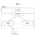
- FIG. 1 illustrates an E-UMTS (Evolved Universal Mobile Telecommunications System) as a wireless communication system.
- the E-UMTS is a system evolved from UMTS (Universal Mobile Telecommunications System) and currently standardized in 3GPP.
- the E-UMTS may be referred to as an LTE (Long Term Evolution) system.
- LTE Long Term Evolution
- the E-UMTS includes a user terminal (UE), an eNode B (eNB), and an access gateway (AG) located at the end of the network (E-UMTS) and connected to an external network.
- the eNB can simultaneously transmit multiple data streams for a broadcast service, multicast service and/or unicast service.
- a cell sets one of bandwidths of 1.25MHz, 2.5MHz, 5MHz, 10MHz, 15MHz and 20MHz for a carrier and provides downlink/uplink transmission service to a plurality of UEs. Different cells may provide different bandwidths.
- An eNB controls data transmission/reception to/from a plurality of UEs. The eNB transmits downlink scheduling information about downlink data to a UE to inform the UE of a time/frequency region in which the downlink data will be transmitted, coding information, data size, hybrid automatic repeat and request (HARQ) related information, etc.
- HARQ hybrid automatic repeat and request
- the eNB transmits uplink scheduling information about uplink data to the UE to inform the UE of a time/frequency region that can be used by the UE, coding information, data size, HARQ related information, etc.
- An interface for user traffic or control traffic transmission may be used between eNBs.
- An object of the present invention devised to solve the problem lies in a method and device for reporting channel state information in a wireless communication system.
- the object of the present invention can be achieved by providing a method for reporting Channel State Information (CSI) at a User Equipment (UE) in a wireless communication system, the method including: measuring downlink signals from a plurality of base stations; feeding back first CSI for a first base station in units of a subband, wherein the first CSI includes identification information for indicating a corresponding subband; and feeding back second CSI for a second base station in units of a subband, wherein the subband corresponding to the second CSI is configured to be identical to the subband corresponding to the first CSI, and the second CSI excludes identification information for indicating a corresponding subband.
- CSI Channel State Information
- a UE configured to transmit CSI in a wireless communication system
- the UE including a radio frequency (RF) module and a processor
- the processor is configured to measure downlink signals from a plurality of base stations, to feed back first CSI for a first base station in units of a subband, and to feed back second CSI for a second base station in units of a subband
- the first CSI includes identification information for indicating a corresponding subband
- the subband corresponding to the second CSI is configured to be identical to the subband corresponding to the first CSI
- the second CSI excludes identification information for indicating a corresponding subband.
- the second CSI may include phase correction information for adjusting a phase between the downlink signal of the first base station and the downlink signal of the second base station.
- the first CSI may be calculated assuming a non-CoMP mode, and wherein the second CSI is calculated assuming a CoMP mode.
- the first CSI and the second CSI may be transmitted through a plurality of neighboring subframes in a subframe set configured for CSI feed-back.
- the first base station may be a serving base station and the second base station may be a cooperative base station.
- FIG. 2 illustrates a control plane and a user plane of a radio interface protocol between a UE and E-UMTS based on the 3GPP wireless access network specification.
- the control plane refers to a path through which control messages that a UE and a network use to manage a call are transmitted.
- the user plane refers to a path through which data generated in an application layer, for example, audio data or Internet packet data is transmitted.
- a physical layer a first layer, provides an information transfer service to a higher layer using a physical channel.
- the physical layer is linked to a medium access control (MAC) layer corresponding to a higher layer through a transport channel.
- Data is transmitted between the MAC layer and the physical layer through the transport channel.
- Data is transmitted between physical layers of a transmitter and a receiver through a physical channel.
- the physical channel uses time and frequency as radio resources.
- the physical layer is modulated according to OFDMA (Orthogonal Frequency Division Multiple Access) on downlink and modulated according to SC-FDMA (Single Carrier Frequency division Multiple Access) on uplink.
- OFDMA Orthogonal Frequency Division Multiple Access
- SC-FDMA Single Carrier Frequency division Multiple Access
- the MAC layer provides a service to a radio link control (RLC) layer corresponding to a higher layer through a logical channel.
- RLC radio link control
- the RLC layer supports reliable data transmission. Functions of the RLC layer may be implemented as functional blocks in the MAC layer.
- a PDCP (Packet Data Convergence Protocol) layer a second layer, performs a header compression function of reducing unnecessary control information to efficiently transmit an IP packet such as IPv4 or IPv6 in a radio interface having a narrow bandwidth.
- RRC Radio Resource Control
- the RRC layer controls logical channels, transport channels and physical channels with respect to configuration, reconfiguration and release of radio bearers (RBs).
- An RB refers to a service provided by the second layer for data transmission between a UE and a network.
- RRC layers of the UE and network exchange RRC messages.
- the UE is in an RRC connected mode when the RRC layers of the UE and network are RRC connected and is otherwise in an idle mode.
- a NAS (Non-Access Stratum) layer higher than the RRC layer performs session management and mobility management.
- a cell constituting an eNB is set to one of bandwidths of 1.25MHz, 2.5MHz, 5MHz, 10MHz, 15MHz and 20MHz and provides a downlink or uplink transmission service to a plurality of UEs. Different cells may provide different bandwidths.
- Downlink transport channels for transmitting data from a network to a UE include a broadcast channel (BCH) for transmitting system information, a paging channel (PCH) for transmitting a paging message, a downlink shared channel (SCH) for transmitting a user traffic or control message, etc.
- BCH broadcast channel
- PCH paging channel
- SCH downlink shared channel
- a traffic or control message of downlink multicast or broadcast service may be transmitted through the downlink SCH or a downlink multicast channel (MCH).
- Uplink transport channels for transmitting data from a UE to a network include a random access channel (RACH) for transmitting an initial control message and an uplink SCH for transmitting a user traffic or control message.
- RACH random access channel
- Logical channels which are higher than transport channels and are mapped to the transport channels include a broadcast control channel (BCCH), a paging control channel (PCCH), a common control channel (CCCH), a multicast control channel (MCCH), a multicast traffic channel (MTCH), etc.
- BCCH broadcast control channel
- PCCH paging control channel
- CCCH common control channel
- MCCH multicast control channel
- MTCH multicast traffic channel
- FIG. 3 illustrates physical channels used for a 3GPP system and a method of transmitting a signal using the physical channels.
- the UE When powered on or when a UE initially enters a cell, the UE performs initial cell search involving synchronization with an eNB (S301). For initial cell search, the UE is synchronized with the eNB and acquires information such as a cell ID by receiving a primary synchronization channel (P-SCH) and a secondary synchronization channel (S-SCH) from the eNB. Then the UE may receive broadcast information from the eNB on a physical broadcast channel. The UE may determine a downlink channel status by receiving a downlink reference signal (DL RS) during initial cell search.
- DL RS downlink reference signal
- the UE may acquire more specific system information by receiving a physical downlink control channel (PDCCH) and receiving a physical downlink shared channel (PDSCH) based on information of the PDCCH (S302).
- PDCCH physical downlink control channel
- PDSCH physical downlink shared channel
- the UE may perform a random access procedure (RACH) to access the eNB (S303 to S306).
- RACH random access procedure
- the UE may transmit a preamble to the eNB on a physical random access channel (PRACH) (S303 and S305) and receive a response message for preamble on a PDCCH and a PDSCH corresponding to the PDCCH (S304 and S306).
- PRACH physical random access channel
- the UE may additionally perform a contention resolution procedure.
- the UE may receive a PDCCH/PDSCH (S307) and transmit a physical uplink shared channel (PUSCH)/physical uplink control channel (PUCCH) (S308), as a general downlink/uplink signal transmission procedure.
- PUSCH physical uplink shared channel
- PUCCH physical uplink control channel
- the UE receives downlink control information (DCI) through a PDCCH.
- the DCI includes control information such as information about allocation or resources to the UE and a format thereof is designed according to application.
- Control information transmitted from the UE to the eNB or control information transmitted from the eNB to the UE through uplink includes a downlink/uplink ACK/NACK signal, a channel quality indicator (CQI), a precoding matrix index (PMI), a rank indicator (RI), etc.
- CQI channel quality indicator
- PMI precoding matrix index
- RI rank indicator
- the UE can transmit the CQI/PMI/RI on a PUSCH and/or a PUCCH.
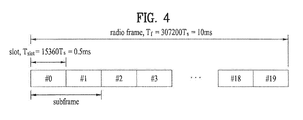
- FIG. 4 illustrates a radio frame structure used in LTE.
- a radio frame has a length of 10ms (307200 ⁇ Ts) and includes 10 subframes of equal size.
- Each subframe has a length of 1ms and includes two slots.
- Each slot has a length of 0.5ms (15360 ⁇ Ts).
- Each slot includes a plurality of OFDM symbols in the time domain and a plurality of resource blocks in the frequency domain.
- one resource block (RB) includes (12 subcarriers ⁇ 7 (or 6) OFDM symbols).
- a unit time for transmitting data, a transmission time interval (TTI), may be defined based on one or more subframes.
- TTI transmission time interval
- FIG. 5 illustrates control channels included in a control region of a subframe in a downlink radio frame.
- a subframe includes 14 OFDM symbols.
- One to three OFDM symbols located in a front portion of the subframe are used as a control region and the remaining eleven to thirteen OFDM symbols are used as a data region.
- R1 to R4 denote reference signals (RSs) or pilot signals with respect to antennas #0 to #3.
- RSs are fixed in a predetermined pattern within the subframe irrespective of the control region and the data region.
- Control channels are allocated to resources to which RSs are not assigned in the control region and traffic channels are allocated to resources to which RSs are not assigned in the data region.
- Control channels allocated to the control region include a physical control format indicator channel (PCFICH), a physical hybrid-ARQ indicator channel (PHICH), a physical downlink control channel (PDCCH), etc.
- PCFICH physical control format indicator channel
- PHICH physical hybrid-ARQ indicator channel
- PDCCH physical downlink control channel
- the PCFICH informs a UE of information regarding the number of OFDM symbols used for a PDCCH for each subframe.
- the PCFICH is transmitted at the first OFDM symbol and set prior to the PHICH and PDCCH.
- the PHICH is composed of 4 resource element groups (REGs) which are dispersed in the control region based on cell ID.
- REG resource element groups
- One REG includes 4 resource elements (REs).
- An RE is a minimum physical resource defined by (a subcarrier ⁇ an OFDM symbol).
- PCFICH values indicate 1 to 3 or 2 to 4 and modulated according to quadrature phase shift keying (QPSK).
- QPSK quadrature phase shift keying
- the PHICH is a HARQ indicator channel and is used to carry HARQ acknowledgment (ACK)/negative-acknowledgment (NACK) signal for uplink transmission. That is, DL ACK/NACK information for UL HARQ is transmitted on the PHICH.
- the PHICH is composed of one REG and is cell-specifically scrambled.
- ACK/NACK is a 1-bit signal and is modulated according to binary phase shift keying (BPSK). Modulated ACK/NACK is spread with a spreading factor (SF) of 2 or 4.
- SF spreading factor
- a plurality of PHICHs mapped to the same resource form a PHICH group. The number of PHICHs multiplexed to the PHICH group is determined by the number of spreading codes.
- the PHICH (group) is repeated three times to obtain diversity gain in the frequency domain and/or time domain.
- the PDCCH is allocated to n OFDM symbols located in the front portion of the subframe.
- n is an integer greater than 1 and is indicated by the PCFICH.
- the PDCCH is composed of one or more CCEs.
- the PDCCH carries information regarding resource allocation of a PCH and DL-SCH, uplink scheduling grant, HARQ information, etc. to each UE or UE group.
- the PCH and DL-SCH are transmitted on a PDSCH. Accordingly, an eNB and a UE generally transmit and receive data through the PDSCH except for specific control information or specific service data.
- Information about one or more UEs to which data of the PDSCH will be transmitted and information about how the UEs receive and decode the PDSCH data are included in a PDCCH and transmitted. For example, if a specific PDCCH is CRC-masked with a radio network temporary identity (RNTI) "A" and information about data transmitted using a radio resource (e.g. frequency position) "B” and a DCI format "C", that is, transport format information (e.g. transport block size, modulation scheme, coding information, etc.) is transmitted through a specific subframe, a UE in a cell monitors the PDCCH using RNTI information included therein. If one or more UEs include the RNTI "A”, the UEs receive the PDCCH and receive a PDSCH indicated by "B” and "C" through information of the received PDCCH.
- RNTI radio network temporary identity
- FIG. 6 illustrates an uplink subframe structure used in LTE.
- an uplink subframe can be divided into a region to which a physical uplink control channel (PUCCH) carrying control information is allocated and a region to which a physical uplink shared channel (PUSCH) carrying user data is allocated.
- the middle part of the subframe is allocated to the PUSCH and both sides of the data region in the frequency domain are allocated to the PUCCH.
- Control information transmitted on the PUCCH includes ACK/NACK used for HARQ, a CQI indicating a downlink channel state, an RI for MIMO, a scheduling request (SR) corresponding to an uplink resource allocation request, etc.
- a PUCCH for one UE uses a resource block occupying different frequencies in slots within the subframe.
- MIMO multiple-input multiple-output
- MIMO uses plural transmit antennas and plural receive antennas and can improve data transmission/reception efficiency. That is, the throughput and performance of a wireless communication system can be improved by using a plurality of antennas at a transmitter or a receiver of the wireless communication system.
- MIMO may be referred to as 'multi-antenna'.
- MIMO does not depend on a single antenna path to receive a whole message. Rather, MIMO completes the message by combining data fragments received through a plurality of antennas. MIMO can increase data rate within a cell area having a specific size or extend system coverage at a given data rate. MIMO is broadly applicable to mobile terminals, relays, etc. It is possible to overcome the limit of throughput of conventional mobile communication sing a single antenna through MIMO.
- FIG. 7 illustrates a configuration of a typical MIMO communication system.
- Tx transmit
- Rx receive
- a theoretical channel transmission capacity is increased, compared to use of a plurality of antennas at only one of the transmitter and the receiver.
- Channel transmission capacity is increased in proportion to the number of antennas. Therefore, transmission rate and frequency efficiency can be increased.
- R o a transmission rate increase rate
- R i corresponds to the smaller of N T and N R .
- R i min N T ⁇ N R
- a MIMO communication system with 4 Tx antennas and 4 Rx antennas may theoretically achieve a four-fold increase in transmission rate, relative to a single-antenna system.
- the theoretical increase in transmission rate of MIMO communication was demonstrated in the mid-1990s, various technologies for improving data rate have been actively studied since then and are now employed in various wireless communication standards such as 3 rd generation mobile communication and next-generation wireless LAN.
- a different transmission power may be applied to each piece of transmission information, s 1 , s 2 , ⁇ , s N T .
- N T transmitted signals x 1 , x 2 , ⁇ ,x N T may be generated by multiplying the transmission power-controlled information vector ⁇ by a weight matrix W.
- the weight matrix W functions to appropriately distribute the transmission information to the Tx antennas according to transmission channel states, etc.
- These N T transmitted signals x 1 , x 2 , ⁇ , x N T are represented as a vector X, which may be determined by Equation 5.
- w ij denotes a weight between an i th Tx antenna and a j th piece of information.
- W is called a weight matrix or a precoding matrix.
- the rank of a channel matrix physically means a maximum number of given channels through which different pieces of information can be transmitted. Accordingly, the rank of the channel matrix is defined as the lesser of the numbers of independent rows and columns. Accordingly, the rank of the channel matrix is not larger than the number of rows or columns.
- the rank of the channel matrix H, rank(H) is limited by Equation 6.
- Equation 7 #of streams ⁇ rank H ⁇ min N T ⁇ N R
- # of streams denotes the number of streams. It is noted that one stream can be transmitted through one or more antennas.
- transmission of one stream through a plurality of antennas can be considered as a spatial diversity scheme and transmission of a plurality of streams through a plurality of antennas can be considered as a spatial multiplexing scheme.
- a hybrid of the spatial diversity and spatial multiplexing is possible.
- CSI channel state information reporting.
- Open-loop MIMO operating without CSI and closed-loop MIMO operating based on CSI are present in LTE.
- each of an eNB and a UE can perform beamforming based on CSI to obtain MIMO antenna multiplexing gain.
- the eNB instructs the UE to feed back CSI with respect to a downlink signal by allocating a PUCCH or a PUSCH to the UE.
- the CSI is categorized into an RI, PMI and CQI.
- the RI indicates rank information of a channel, as described above, and represents the number of streams that can be received by a UE through the same time-frequency resource.
- the RI is determined by long term fading of the channel, and thus the RI is fed back to an eNB at a longer period than PMI and CQI.
- the PMI is a value in which spatial characteristics of a channel are reflected and indicates a precoding matrix index of an eNB preferred by a UE based on a metric such as SINR.
- the CQI indicates channel intensity and represents a reception SINR that can be obtained by the eNB using the PMI.
- CSI includes a CQI, PMI and RI although it is not limited thereto in LTE, and all or some of the CQI, PMI and RI are transmitted according to the transmission mode of each UE.
- Periodic transmission of CSI is referred to as periodic reporting and transmission of CSI at the request of an eNB is referred to as aperiodic reporting.
- a request bit included in uplink scheduling information transmitted from the eNB is sent to a UE. Then, the UE transmits CSI considering a transmission mode thereof to the eNB through a PUSCH.
- a period and an offset of the period are semi-statically signaled to each UE through a higher layer signal on a subframe basis.
- Each UE delivers CSI considering the transmission mode thereof to the eNB through a PUCCH in a predetermined period. If uplink data is present in a subframe in which CSI is transmitted, the CSI is transmitted with the uplink data through a PUSCH.
- the eNB transmits transmission timing information suitable for each UE to each UE in consideration of channel state of each UE, UE distribution in a cell, etc.
- the transmission timing information includes a period in which CSI is transmitted, an offset, etc. and may be transmitted to each UE through an RRC message.
- FIGS. 8 to 11 illustrate periodic CSI reporting in LTE.
- the CQI reporting modes are categorized into a wideband (WB) CQI mode and a subband (SB) CQI mode according to CQI feedback type and into a no PI mode and a single PMI mode according to whether a PMI is transmitted.
- WB wideband
- SB subband
- Each UE receives information composed of a combination of a period and an offset through RRC signaling for periodic CQI reporting.
- FIG. 9 illustrates an example of transmitting CSI when information representing ⁇ period '5', offset '1' ⁇ is signaled to a UE.
- the UE upon reception of the information representing a period of '5' and an offset of '1', the UE transmits CSI in 5 subframes with an offset corresponding to one subframe from subframe #0 in a direction in which the subframe index increases. While the CSI is basically transmitted through a PUCCH, when a PUSCH for transmitting data is present in the same time, the CSI is transmitted with the data through the PUSCH.
- the subframe index is composed of a system frame number n f and a slot index n s (0 to 19). Since a subframe includes two slots, the subframe index can be defined by 10*n f +floor(n s /2).
- floor() denotes a floor function.
- a scheme of transmitting a WB CQI only and a scheme of transmitting both the WB CQI and SB CQI are present.
- CQI information about the overall band is transmitted in subframes corresponding to a CQI transmission period.
- PMI feedback type as illustrated in FIG. 8
- the PMI and CQI are transmitted together.
- the WB CQI and SB CQI are alternately transmitted.
- FIG. 10 illustrates a system having a system bandwidth corresponding to 16 RBs.
- the system bandwidth is composed of two bandwidth parts (BPs) BP0 and BP1 each of which includes two subbands (SBs) SB0 and SB1 each of which is composed of 4 RBs.
- BPs bandwidth parts
- SBs subbands
- the number of BPs and the size of each SB may be varied according to system bandwidth.
- the number of SBs constituting each BP may depend on the number of RBs, the number of BPs and SB size.
- the WB CQI is transmitted in a first CQI transmission subframe and a CQI corresponding to the SB having a good channel state between SB0 and SB1 belonging to BP0 and the index of the corresponding SB are transmitted in the next CQI transmission subframe. Then, a CQI corresponding to the SB in good channel state between SB0 and SB1 belonging to BP1 and the index of the corresponding SB are transmitted in the next CQI transmission subframe.
- the WB CQI is transmitted and then CQI information about respective BPs is sequentially transmitted.
- CQI information about BPs can be sequentially transmitted one to four times between two WB CQIs.
- Information about how many times each BP CQI is sequentially transmitted is signaled by a higher layer (e.g. RRC layer).
- FIG. 11 (a) illustrates an example of transmitting both the WB CQI and SB CQI when information representing ⁇ period '5', offset '1' ⁇ is signaled to a UE.
- a CQI can be transmitted only in subframes corresponding to a signaled period and offset irrespective of CQI type.
- FIG. 11(b) illustrates a case in which an RI is additionally transmitted.
- the RI can be signaled by a higher layer (e.g. RRC layer) as a combination of information about a multiple of the WB CQI transmission period, which corresponds to an RI transmission period, and an offset in the RI transmission period.
- RRC layer e.g. RRC layer
- the offset of the RI is signaled as a value relative to the offset of the CQI. For example, if the offset of the CQI is '1' and the offset of the RI is '0', the RI has the same offset as that of the CQI.
- the offset of the RI is defined as 0 or a negative value.
- FIG. 11(b) assumes a case in which the RI transmission period is equal to the WB CQI transmission period and the offset of the RI is '-1' in the same environment as FIG. 11(a) .
- the RI transmission period is identical to the WB CQI transmission period since the RI transmission period is equal to the WB CQI transmission period.
- the offset of the RI is '-1', and thus the RI is transmitted on the basis of '-1' (i.e. subframe #0) with respect to the CQI offset '1'.
- '-1' i.e. subframe #0
- the WB CQI transmission subframe and RI transmission subframe overlap. In this case, the WB CQI is dropped and the RI is transmitted.
- MU-MIMO multi-user MIMO
- MU-MIMO multi-user MIMO
- accuracy of CSI may largely affect not only a UE that reports the CSI but also interference of other multiplexed UEs. Accordingly, MU-MIMO requires more accurate CSI reporting than SU-MIMO.
- a final PMI is divided into W1 corresponding to a long-term and/or wideband PMI and W2 corresponding to a short-term and/or subband PMI.
- a long-term covariance matrix of a channel can be used as a hierarchical codebook transformation constituting a final PMI based on W1 and W2.
- W norm W ⁇ 1 ⁇ W ⁇ 2
- W2 corresponds to a short-term PMI and is a codeword of a codebook configured to reflect short-term channel state information
- W is a codeword (in other words, precoding matrix) of a final codebook
- norm (A) denotes a matrix in which the norm of each column of matrix A is normalized to 1.
- W1 and W2 have structures as represented by Equation 9.
- W ⁇ 1 i X i 0 0 X i , where X i is Nt / 2 by M matrix .
- Nt denotes the number of Tx antennas
- M is the number of columns of a matrix X i and represents that the matrix X i includes M candidate column vectors
- e M k , e M l and e M m respectively indicate k-th, l-th and m-th column vectors in which only k-th, 1-th and m-th elements from among M elements are 1 and the remaining elements are 0.
- ⁇ j , ⁇ j and ⁇ j are complex values having unit norm and represent application of phase rotation to the k-th, 1-th and m-th column vectors of the matrix X i .
- i is an integer greater than 0 and denotes a PMI indicating W1
- j is an integer greater than 0 and denotes a PMI indicating W2.
- cross polarized antennas are used.
- antenna spacing is narrow, for example, when a distance between neighboring antennas is less than half a signal wavelength, correlation characteristics of a channel are reflected in the codeword structure.
- the cross polarized antennas can be categorized into a horizontal antenna group and a vertical antenna group which have uniform linear array (ULA) antenna characteristics and are co-located.
- ULA uniform linear array
- rank-1 codeword generated in the above-described structure is represented in Equation 10.
- W ⁇ 1 i * W ⁇ 2 j X i k ⁇ j ⁇ X i k
- the codeword is represented by a vector of N T (the number of Tx antennas) ⁇ 1 and is composed of an upper vector X i ( k ) and a lower vector ⁇ j X i ( k ) which respectively represent correlations between horizontal antenna groups and vertical antenna groups.
- X i ( k ) is preferably represented as a vector having linear phase increment in which correlation between antennas in each antenna group is reflected and can use a DFT matrix.
- FIG. 12 illustrates periodic CSI reporting, which is being discussed in LTE-A.
- LTE-A sets a precoder type indication (PTI) parameter which is a 1-bit indicator and considers two types of subdivided periodic reporting modes according to PTI values, as illustrated in FIG. 12 .
- PTI precoder type indication
- W1 and W2 are codewords constituting a hierarchical codebook described with reference to Equations 8 and 9. Both W1 and W2 need to be determined in order to set a precoding matrix W accomplished by combining W1 and W2.
- Report 1 reports an RI and a 1-bit PTI value.
- N offset,CQI corresponds to the offset value illustrated in FIG. 9 and N c denotes a subframe spacing between neighboring Reports 2 or Reports 3.
- the first subframe set is composed of subframes having odd-numbered indices.
- n f denotes a system frame number (or radio frame index)
- n s denotes a slot index in a radio frame
- floor() represents a floor function
- 'A mod B' represents the remainder obtained by dividing A by B.
- K is determined by higher layer signaling and J denotes the number of BPs.
- M RI is determined by higher layer signaling.
- N offset,RI denotes a relative offset value for an RI.
- the RI, W1 and W2 are related to one another. For example, W1 and W2 are calculated based on the RI and W2 is calculated based on W1.
- the corresponding eNB can be aware of a final W from W1 and W2.
- LTE-A is expected to support coordinated multi-point (CoMP) transmission, which was not supported in any legacy standards, in order to improve data rate.
- CoMP transmission refers to a scheme through which two or more eNBs or cells cooperatively communicate with UEs to improve the performance of communication between a UE and an eNB (cell or sector) located in a shadow area.
- CoMP transmission schemes may be categorized into joint processing (CoMP-JP) in the form of coordinated MIMO through data sharing and scheduling/beamforming (CoMP-CS/CB).
- CoMP-JP joint processing
- CoMP-CS/CB data sharing and scheduling/beamforming
- a UE can simultaneously receive data from plural eNBs that perform CoMP transmission and improve reception performance by combining signals received from the eNBs according to CoMP-JP (Joint transmission (JT)).
- CoMP-JP Joint transmission
- a method by which one of eNBs that perform CoMP transmission transmits data to the UE at a specific time may be considered.
- DPS dynamic point selection
- the UE can instantaneously receive data from an eNB, that is, a serving eNB through beamforming.
- CoMP-JP When CoMP-JP is applied to uplink transmission, eNBs can simultaneously receive a PUSCH signal from a UE (Joint Reception (JR)). In the case of CoMP-CS/CB, only one eNB can receive a PUSCH. Employment of CoMP-CS/CB can be determined by coordinated cells (or eNBs).
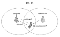
- FIG. 13 illustrates an exemplary CoMP CB operation.
- a UE i.e., a CoMP UE receives control information from a serving eNB (s-eNB) to operate and receives data only from the s-eNB.
- the CoMP UE can estimate radio channels from a c-eNB as well as the s-eNB and report CSI feedback for each eNB to the s-eNB.
- the s-eNB can transmit PMI recommendation information to the c-eNB on the basis of a reported PMI for the c-eNB.
- the c-eNB can perform beam avoidance and precoding for the same to minimize interference applied to the CoMP UE using the PMI recommendation information.
- FIG. 13 illustrates only one c-eNB
- the present invention is applicable to a coordinating set including a plurality of c-eNBs.
- the present invention can be applied to not only inter-site CoMP in which an s-eNB and a c-eNB are located at a distance from each other, as illustrated in FIG. 13 , but also intra-site CoMP in which eNBs in a coordinating set are geographically co-located or heterogeneous networks including a hybrid of inter-site CoMP and intra-site CoMP.
- CoMP transmission higher CSI accuracy is required.
- multiple eNBs cooperatively transmit the same data to a specific UE in the CoMP JT system, and thus the CoMP JT system can be regarded as a MIMO system in which antennas are geographically distributed.
- JT based MU-MIMO requires high CSI accuracy like single-cell MU-MIMO.
- accurate CSI is needed in order to avoid interference of a neighboring cell, applied to a serving cell.
- the present invention proposes a periodic CSI reporting method by which a UE periodically feeds back channel state information (CSI) on each base station (or cell) in a coordinating set for CoMP (e.g. CS/CB, JP, etc) operation.
- the periodic CSI feedback method proposed by the present invention is applicable to non-CoMP operation and dynamic cell selection (DCS) as well as CoMP operation, as necessary.
- DCS dynamic cell selection
- the present invention is applicable to a case in which channel information on each cell in a coordinating set is fed back as subband (SB) CSI as well as wideband (WB) CSI.
- SB subband
- WB wideband
- a CoMP UE feeds back WB CSI for each of an s-eNB and a c-eNB. Since all feedback content for the s-eNB and c-eNB is WB CSI, the UE can transmit a report for the s-eNB (e.g. s-eNB WB PMI + WB CQI) first and then transmit a report for the c-eNBs (e.g., c-eNB WB PMI + WB CQI). If plural c-eNBs are present in a CoMP coordinating set, the reporting order of CSI for the c-eNBs can be sequentially defined.
- s-eNB e.g. s-eNB WB PMI + WB CQI
- the reporting order of CSI for the c-eNBs can be defined in various manners according to a predetermined rule.
- the UE can report WB CSI for the c-eNBs prior to WB CSI for the s-eNB.
- the frequency of reporting CSI for the s-eNB may be set to higher than the frequency of reporting CSI for a c-eNB.
- the reporting order of CSI for eNBs may be appropriately determined according to various conditions, for example, a feedback period, number of c-eNBs, etc. in combination with or separately from the above examples.
- RIs Prior to reporting of PMIs/CQIs for eNBs in the CoMP coordinating set, RIs can be fed back. If the same RI is configured for all eNBs in the CoMP coordinating set (e.g., an RI suitable for the channel of the s-eNB is commonly used for all eNBs in the CoMP coordinating set, an RI capable of representing RIs suitable for channels of eNBs in the coordinating set is used, etc.), the UE can transmit the common RI in a first reporting instance (e.g. subframe) and report PMIs/CQIs calculated based on the RI in a cyclic manner until a period in which a new RI is reported.
- a first reporting instance e.g. subframe
- RIs may be independently reported for respective eNBs in the CoMP coordinating set.
- the RIs for the respective eNBs in the coordinating set can be reported in a predefined order prior to cyclic reporting of PMIs/CQIs for the eNBs in the CoMP coordinating set or the RIs can be reported in predefined instances prior to reporting of the first PMI/CQI based on a feedback chain for the eNBs.
- a relative phase corrector may be added to feedback information on a c-eNB. That is, only PMI + CQI (which can be defined as a CQI in the case of non-CoMP) can be reported as feedback information for the s-eNB and PMI + CQI (which can be defined as a CQI in the case of CoMP) + RPC can be reported as feedback information for a c-eNB.
- the RPC can be used to adjust a relative phase between signals from eNBs in the CoMP coordinating set such that the sum of the signals from the eNBs becomes a constructive sum when the signals are summed at a UE.
- a feedback instance may have an insufficient bit width for adding RPC information (or an additional coding gain may be needed).
- PMI sub-sampling may be employed to reduce the number of bits for PMI feedback.
- PMI sub-sampling is a method for decreasing the number of bits for PMI feedback by limiting a target of PMI feedback to some subsets of a PMI set.
- a CQI for a c-eNB may be transmitted in the form of a delta CQI with respect to the CQI for the s-eNB.
- RI>1 for the non-CoMP CQI with respect to the s-eNB, a CQI corresponding to codeword 0 and a CQI corresponding to codeword 1 can be separately calculated and consecutively transmitted.
- a non-CoMP CQI refers to a CQI on the assumption that CoMP is not applied, that is, CQI feedback is performed in the single-cell mode and a CoMP CQI refers to a CQI on the assumption that CQI feedback is performed in the CoMP mode.
- PMI + CQI reporting for each eNB (PMI + CQI + RPC in the case of a c-eNB)
- a hierarchical codebook in which PMIs are categorized into long term and/or wideband PMI (W1) and short tem and/or subband PMI (W2) may be used.
- Reports of PMIs + CQIs (+ RPCs) for eNBs may be transmitted through two or more reporting instances due to limited payload size per reporting instance according to characteristics of periodic reporting.
- CSI feedback for eNBs in the CoMP coordinating set may be reported by eNBs in a cyclic manner.
- cyclic CSI reporting by eNBs can be performed in such a manner that full information (e.g. PMI + CQI (+ RPC)) about each eNB is reported.
- full information e.g. PMI + CQI (+ RPC)
- plural consecutive reporting instances are grouped for each eNB.
- cyclic CSI reporting by eNBs may be performed based on reporting instance.
- CSI feedback can be performed in such a manner that feedback information regarding eNBs is reported in a cyclic manner in a reporting instance and feedback information regarding the eNBs is reported in a circulative manner in the next reporting instance.
- FIGS. 14 and 15 illustrate cases in which a CoMP UE reports wideband (WB) CSI for each of an s-eNB and a c-eNB according to the present embodiment. While FIGS. 14 and 15 assume that three c-eNBs (c-eNB 1 , c-eNB 2 and c-eNB 3 ) are present, the number of c-eNBs is not limited thereto.
- WB wideband
- FIG. 14 illustrates a case in which a non-hierarchical codebook is used.
- CSI e.g. PMIs and/or CQIs
- the CQI for the s-eNB may be defined as a non-CoMP CQI.
- a CQI for a c-eNB can be defined as a CoMP CQI in which a gain obtained when the c-eNB and the s-eNB perform CoMP is reflected.
- CSI e.g. WB PMIs and WB CQIs
- CSI e.g. WB PMIs and WB CQIs
- the CSI for c-eNB 2 may include an RPC.
- the RPC may be reported along with the PMI/CQI or reported in a separate reporting instance.
- the bit width of the PMI/CQI can be reduced using PMI sub-sampling or a delta CQI to secure a bit width for the RPC.
- FIG. 15 illustrates a case in which a hierarchical codebook is used.
- the case of FIG. 15 is distinguished from the case of FIG. 14 in that CSI feedback for each eNB in the CoMP coordinating set is transmitted through plural (e.g. two) reporting instances.
- the CQI for the s-eNB can be defined as a non-CoMP CQI.
- the delta CQI represents a difference between the non-CoMP CQI for the s-eNB and a CQI for a c-eNB.
- rank of 2 or more it is possible to reduce bit width of a CQI report for a c-eNB by feeding back a common delta CQI only on the assumption that non-CoMP CQIs are changed by the delta CQI through CoMP for all codewords.
- a method of reducing the number of bits necessary for PMI transmission using PMI sub-sampling may be considered.
- BP bandwidth
- PMI + CQI corresponding to the selected subband are fed back. If a selected subband is not predefined, a best subband is selected from each BP and an L-bit subband selection indicator (SSI) indicating the selected subband is additionally fed back. Accordingly, PMI + CQI + SSI are transmitted in the case of subband CSI reporting.
- wideband CSI for c-eNBs is reported first and subband PMI + subband CQI + SSI for the s-eNB can be selected based on the reported wideband CSI for the c-eNBs such that CoMP performance is maximized.
- the subband CQI for the s-eNB is preferably defined as a CQI (i.e. CoMP CQI) expected when the s-eNB and the c-eNBs perform CoMP.
- wideband CSI for a c-eNB estimated to have the highest CoMP gain can be reported first and then as many subband PMIs + subband CQIs + SSIs as the number of subbands to be transmitted, for the s-eNB, which are appropriately matched with the wideband CSI for the c-eNB, can be reported. Subsequently, wideband CSI for a c-eNB estimated to have the second highest CoMP gain can be reported and then as many s-eNB subband PMIs + subband CQIs + SSIs as the number of subbands to be transmitted, which are appropriately matched with the wideband CSI for the c-eNB, can be reported.
- c-eNB indices arranged in descending order of CoMP gain need to be signaled.
- an RI reported prior to PMI + CQI may be reported along with c-eNB index information in a reporting instance of the RI or the c-eNB index information may be predefined through other methods.
- the RI and c-eNB index information can be joint-coded.
- wideband CSI for c-eNBs may be sequentially reported based on c-eNB (or cell) index instead of CoMP gain.
- the c-eNB index information need not be included in feedback information.
- RPC information may be added to the subband report for the s-eNB.
- RPC information may be added to the subband report for the s-eNB.
- a subband can be selected in a predetermined pattern according to predefined cycling.
- a subband selection pattern may be previously provided through higher layer signaling.
- a reporting instance for CSI feedback for an eNB may be M (>1) subframes.
- the above-described schemes can be extended in such a manner that report content in the M subframes is distributed according to a rule determined for a subframe based reporting instance and transmitted.
- FIGS. 16 and 17 illustrate cases in which a CoMP UE reports SB CSI for the s-eNB and reports WB CSI for c-eNBs according to the present embodiment.
- FIG. 16 illustrates a case in which a non-hierarchical codebook is used. While FIG. 16 assumes two c-eNBs (c-eNB 1 and c-eNB 2 ), the number of c-eNBs is not limited thereto. In this case, the CoMP UE reports WB CSI for each of c-eNB 1 and c-eNB 2 and reports SB SCI for the s-eNB.
- the CQI may be defined as a non-CoMP CQI when c-eNB 1 is selected according to dynamic cell selection.
- the SB CSI for the s-eNB includes at least one of a SB PMI, a SB delta CQI, an SSI and an RPC.
- the delta CQI may be defined as a CQI gain varied during CoMP with respect to a non-CoMP CQI reported prior thereto and may be commonly applied to two codewords.
- the SSI and RPC can be transmitted through a bit width secured using the delta CQI.
- the SSI can be omitted and thus a bit width for RPC information can be additionally secured.
- FIG. 17 illustrates a case in which a hierarchical codebook is used. While FIG. 17 assumes three c-eNBs (c-eNB 1 , c-eNB 2 and c-eNB 3 ), the number of c-eNBs is not limited thereto.
- the case of FIG. 17 is distinguished from the case of FIG. 16 in that CSI feedback for each eNB in the CoMP coordinating set is transmitted through plural (e.g. two) reporting instances.
- FIG. 17 illustrates an example of transmission of report content before transmission of the next RI and PTI according to a predetermined rule when the 1-bit indicator PTI, which is discussed in LTE-A, and RI are simultaneously transmitted.
- the CQI can be defined as a non-CoMP CQI.
- WB W2 for c-eNBs can be additionally sub-sampled. Accordingly, additional bit width can be secured to transmit RPC information along with CSI.
- W2 may be additionally sub-sampled in order to include RPC information.
- Subband selection may be defined according to predetermined cycling.
- SB PMIs + SB CQIs (non-CoMP/CoMP CQIs, preferably, non-CoMP CQIs) + SSIs for the c-eNBs can be selected such that CoMP performance is maximized on the basis of previously reported s-eNB wideband CSI.
- a subband CQI for a c-eNB can be defined as a CQI (i.e. CoMP CQI) expected when the c-eNB performs CoMP with the s-eNB.
- RPC information may be added to subband reports for the c-eNBs in the same manner as the above embodiment.
- the subband PMIs can be sub-sampled or the subband CQIs can be defined as delta CQIs to reduce bit widths and RPC information can be added to the subband PMIs and subband CQIs.
- a subband selection information bit SSI can be omitted and a subband predetermined according to predefined cycling can be selected to transmit RPC information instead of the SSI.
- a reporting instance of CSI feedback for an eNB may correspond to M (>1) subframes.
- the above-described schemes may be extended in such a manner that report content through M subframes is distributed to subframe-based reporting instances according to a predetermined rule and transmitted.
- FIG. 18 illustrates a case in which s-eNB CSI is WB CSI and c-eNB CSI is SB CSI.
- the present embodiment proposes a feedback scheme by which the s-eNB and c-eNBs can perform subband CSI based CoMP by applying a periodic subband CSI feedback mode, which is actively discussed in LTE-A, to CSI reporting for c-eNBs as well as CSI reporting for the s-eNB.
- the proposed feedback scheme can maximize frequency diversity and provide more accurate channel information in the frequency domain.
- SB PMIs + SB CQIs (non-CoMP/CoMP CQIs, preferably, non-CoMP CQIs) + SSIs for the s-eNBs as the number of subbands to be transmitted can be reported and as many SB PMIs + SB CQIs (non-CoMP/CoMP CQIs) + RPCs for each c-eNB in a predefined specific order as the number of subbands to be transmitted can be reported.
- CSI feedback may be performed in a cyclic manner for the c-eNBs.
- feedback information about a c-eNB includes an RPC instead of an SSI.
- a subband selection order of a c-eNB may be identical to a subband selection order of the s-eNB according to SSI. Since CoMP transmission can be performed on the same subband, the subband selection order of the c-eNB can correspond to the subband selection order of the s-eNB.
- CSI feedback may be transmitted in a cyclic manner for selected subband indices in such a manner that all s-eNB SB CSI and c-eNB SB CSI with respect to a subband index are reported for all eNBs in the coordinating set and then all s-eNB SB CSI and c-eNB SB CSI with respect to the next subband index are reported for all eNBs in the coordinating set.
- the SB CSI for the c-eNB refers to CSI in a subband indicated by the SSI of SB CSI of the s-eNB, which is paired with the SB CSI of the c-eNB.
- 'pair' means that an SB report of a c-eNB is predefined according to a predetermined rule such that the SB report of the c-eNB conforms to an SSI of an SB report of a specific s-eNB.
- FIG. 19 illustrates a case in which all CSI reports for the s-eNB and c-eNBs correspond to SB CSI. While the case of FIG. 19 is based on the assumption that one c-eNB (c-eNB 1 ) is present, the number of c-eNBs is not limited thereto.
- s-eNB SB CSI can be transmitted in a reporting instance and then SB CSI of c-eNB 1 , which corresponds to the same SB index as that of the s-eNB SB CSI can be transmitted in the next reporting instance.
- An appropriate scheme can be selected from among the above-described CSI feedback schemes according to the above embodiments according to frequency characteristics of a channel for each eNB in the coordinating set, estimated by the UE, (and/or antenna correlation information about each eNB). For example, WB CSI feedback is preferable when frequency selectivity is low or antenna correlation is high for each eNB and frequency diversity gain can be advantageously maximized through SB CSI feedback when frequency selectivity is high and antenna correlation is low and thus beam direction selectivity is sufficient.
- the present embodiment proposes a scheme by which the UE dynamically selects a feedback scheme for different report content according to channel characteristics per eNB.
- a specific parameter referred to as a feedback mode parameter for convenience
- the UE can determine the parameter according to a channel state thereof to dynamically select a feedback mode.
- the 1-bit PTI parameter currently discussed in LTE-A
- the number of bits allocated to the PTI can be increased to enable dynamic selection of more CoMP feedback modes.
- an eNB may set the purpose (e.g.
- the feedback mode parameter may be reported along with an RI in an RI feedback reporting instance or reported in a separate instance.
- mapping tables showing mapping relations between a 2-bit PTI and a 1-bit PTI and feedback schemes to be dynamically selected when the parameter for dynamic selection of a CoMP mode is referred to as a PTI in the same manner as in LTE-A.
- a PTI in the same manner as in LTE-A.
- 2-bit bitmap (PTI) Feedback report content 00 s-eNB WB CSI report and c-eNB WB CSI report (Refer to embodiment 1) 01 s-eNB SB CSI report and c-eNB WB CSI report (Refer to embodiment 2) 10 s-eNB SB CSI report and c-eNB SB CSI report (Refer to embodiment 3) 11 Single cell (WB and SB reports)
- Table 1 shows an example of dynamic selection of report content when a 2-bit PTI is used. The number of bits of the PTI can be further increased. In this case, a feedback report such as an s-eNB WB CSI report and c-eNB SB CSI report (refer to embodiment 4) can be added to report content to be dynamically selected.
- a feedback report such as an s-eNB WB CSI report and c-eNB SB CSI report (refer to embodiment 4) can be added to report content to be dynamically selected.
- PTI 1-bit bitmap
- Feedback report content 0 CoMP (WB report) 1 Single cell (SB report)
- Table 2 shows an example of utilization of a 1-bit PTI.
- Table 2 shows a modification of the PTI for the purpose of CoMP operation.
- a CoMP feedback mode used for CSI reporting can be pre-designated through L1/L2 signaling or higher layer signaling or fixed to a specific feedback mode.
- FIG. 20 illustrates a case in which report content is dynamically selected according to the scheme of Table 2.
- reporting for respective eNBs can be performed in a cyclic manner according to the number of c-eNBs.
- the UE can transmits a PTI of 1 and then feed back CSI in the single-cell reporting mode (e.g. SB CSI).
- SB CSI single-cell reporting mode
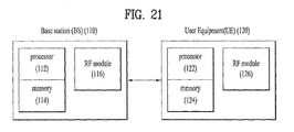
- FIG. 21 illustrates a BS and a UE applicable to an embodiment of the present invention.
- a wireless communication system including a relay communication is performed between a BS and the relay in a backhaul link and between the relay and a UE in an access link. Accordingly, the BS or UE can be replaced by a relay as necessary.
- an RF communication system includes a BS 110 and a UE 120.
- the BS 110 includes a processor 112, a memory 114 and an RF unit 116.
- the processor 112 may be configured to implement the procedures and/or methods proposed by the present invention.
- the memory 114 is connected to the processor 112 and stores various types of information relating to operations of the processor 112.
- the RF unit 116 is connected to the processor 112 and transmits and/or receives RF signals.
- the UE 120 includes a processor 122, a memory 124 and an RF unit 126.
- the processor 122 may be configured to implement the procedures and/or methods proposed by the present invention.
- the memory 124 is connected to the processor 122 and stores various types of information relating to operations of the processor 122.
- the RF unit 126 is connected to the processor 122 and transmits and/or receives RF signals.
- the BS 110 and the UE 120 may have a single antenna or multiple antennas.
- a specific operation described as performed by the BS may be performed by an upper node of the BS. Namely, it is apparent that, in a network comprised of a plurality of network nodes including a BS, various operations performed for communication with an MS may be performed by the BS, or network nodes other than the BS.
- the term 'eNB' may be replaced with the term 'fixed station', 'Node B', 'Base Station (BS)', 'access point', etc.
- the embodiments of the present invention may be achieved by various means, for example, hardware, firmware, software, or a combination thereof.
- the methods according to the embodiments of the present invention may be achieved by one or more Application Specific Integrated Circuits (ASICs), Digital Signal Processors (DSPs), Digital Signal Processing Devices (DSPDs), Programmable Logic Devices (PLDs), Field Programmable Gate Arrays (FPGAs), processors, controllers, microcontrollers, microprocessors, etc.
- ASICs Application Specific Integrated Circuits
- DSPs Digital Signal Processors
- DSPDs Digital Signal Processing Devices
- PLDs Programmable Logic Devices
- FPGAs Field Programmable Gate Arrays
- processors controllers, microcontrollers, microprocessors, etc.
- the embodiments of the present invention may be implemented in the form of a module, a procedure, a function, etc.
- software code may be stored in a memory unit and executed by a processor.
- the memory unit is located at the interior or exterior of the processor and may transmit and receive data to and from the processor via various known means.
- the method and device for reporting channel state information in a wireless communication system can be applied to various wireless communication systems other than 3GPP LTE.
Applications Claiming Priority (2)
| Application Number | Priority Date | Filing Date | Title |
|---|---|---|---|
| US201061427101P | 2010-12-23 | 2010-12-23 | |
| PCT/KR2011/009987 WO2012087046A2 (fr) | 2010-12-23 | 2011-12-22 | Procédé pour rapporter des données d'état de canal dans un système de communication sans fil et appareil pour mettre en œuvre ce procédé |
Publications (3)
| Publication Number | Publication Date |
|---|---|
| EP2658155A2 true EP2658155A2 (fr) | 2013-10-30 |
| EP2658155A4 EP2658155A4 (fr) | 2017-08-16 |
| EP2658155B1 EP2658155B1 (fr) | 2018-10-10 |
Family
ID=46314647
Family Applications (1)
| Application Number | Title | Priority Date | Filing Date |
|---|---|---|---|
| EP11851478.5A Not-in-force EP2658155B1 (fr) | 2010-12-23 | 2011-12-22 | Procédé pour rapporter des données d'état de canal dans un système de communication sans fil et appareil pour mettre en oeuvre ce procédé |
Country Status (4)
| Country | Link |
|---|---|
| US (1) | US9357419B2 (fr) |
| EP (1) | EP2658155B1 (fr) |
| KR (1) | KR101769382B1 (fr) |
| WO (1) | WO2012087046A2 (fr) |
Cited By (3)
| Publication number | Priority date | Publication date | Assignee | Title |
|---|---|---|---|---|
| EP2753002A4 (fr) * | 2011-09-02 | 2015-04-29 | Lg Electronics Inc | Procédé et appareil de transmission d'informations d'état de canal dans un système de communication sans fil |
| CN108029028A (zh) * | 2015-08-06 | 2018-05-11 | 夏普株式会社 | 终端装置、基站装置、通信方法以及集成电路 |
| EP3366064A4 (fr) * | 2015-10-21 | 2018-12-05 | Telefonaktiebolaget LM Ericsson (PUBL) | Diffusion optimisée de messages d'informations système |
Families Citing this family (15)
| Publication number | Priority date | Publication date | Assignee | Title |
|---|---|---|---|---|
| WO2012094803A1 (fr) * | 2011-01-10 | 2012-07-19 | Nokia Siemens Networks Oy | Indication de sets de transmission dynamique |
| US20130083681A1 (en) * | 2011-09-30 | 2013-04-04 | Research In Motion Limited | Methods of Channel State Information Feedback and Transmission in Coordinated Multi-Point Wireless Communications System |
| CN102957515B (zh) * | 2011-08-22 | 2018-09-25 | 索尼公司 | 信道信息反馈方法、用户设备、发送数据方法和基站 |
| US8797966B2 (en) | 2011-09-23 | 2014-08-05 | Ofinno Technologies, Llc | Channel state information transmission |
| US8885569B2 (en) | 2011-12-19 | 2014-11-11 | Ofinno Technologies, Llc | Beamforming signaling in a wireless network |
| US8953478B2 (en) * | 2012-01-27 | 2015-02-10 | Intel Corporation | Evolved node B and method for coherent coordinated multipoint transmission with per CSI-RS feedback |
| CN104106282B (zh) * | 2012-01-30 | 2018-11-30 | 日本电气株式会社 | 无线通信系统和用于控制报告设定的方法 |
| CN112954741B (zh) * | 2013-12-26 | 2024-03-15 | 索尼公司 | 移动终端、以及移动终端之间协作传输的实现方法 |
| WO2016137061A1 (fr) * | 2015-02-26 | 2016-09-01 | 엘지전자 주식회사 | Procédé de rétroaction de csi dans un système de communication sans fil, et appareil associé |
| US10097254B2 (en) * | 2016-04-18 | 2018-10-09 | Qualcomm Incorporated | Channel state information estimation and channel information reporting |
| BR112019014029A2 (pt) * | 2017-01-06 | 2020-02-04 | Guangdong Oppo Mobile Telecommunications Corp Ltd | método de medição, estação-base e dispositivo de terminal |
| WO2018126456A1 (fr) * | 2017-01-06 | 2018-07-12 | 广东欧珀移动通信有限公司 | Procédé de mesurage, station de base, et terminal |
| MX2019002549A (es) * | 2017-03-25 | 2019-06-17 | Lg Electronics Inc | Metodo para que una terminal reciba una señal de referencia de seguimiento de fase en un sistema de comunicacion inalambrico y un dispositivo que soporta al mismo. |
| US10554359B2 (en) | 2017-03-25 | 2020-02-04 | Lg Electronics Inc. | Method of receiving phase tracking reference signal by user equipment in wireless communication system and device for supporting same |
| CN109150411B (zh) * | 2017-06-16 | 2021-06-18 | 北京紫光展锐通信技术有限公司 | 信道状态信息上报方法、装置及用户设备 |
Family Cites Families (4)
| Publication number | Priority date | Publication date | Assignee | Title |
|---|---|---|---|---|
| KR101481166B1 (ko) * | 2007-06-25 | 2015-01-28 | 엘지전자 주식회사 | 다중안테나 시스템에서의 귀환데이터 전송 방법 |
| US8964656B2 (en) | 2009-04-02 | 2015-02-24 | Lg Electronics Inc. | Method of transmitting channel state information in wireless communication system |
| US8917707B2 (en) * | 2009-04-24 | 2014-12-23 | Samsung Electronics Co., Ltd. | Techniques for channel state information feedback in wireless communication system |
| CN103262601B (zh) * | 2010-12-13 | 2016-09-14 | 诺基亚通信公司 | 用于在多小区通信中提供信道反馈的机制 |
-
2011
- 2011-12-22 KR KR1020137016603A patent/KR101769382B1/ko active IP Right Grant
- 2011-12-22 WO PCT/KR2011/009987 patent/WO2012087046A2/fr active Application Filing
- 2011-12-22 US US13/993,000 patent/US9357419B2/en active Active
- 2011-12-22 EP EP11851478.5A patent/EP2658155B1/fr not_active Not-in-force
Non-Patent Citations (1)
| Title |
|---|
| See references of WO2012087046A2 * |
Cited By (8)
| Publication number | Priority date | Publication date | Assignee | Title |
|---|---|---|---|---|
| EP2753002A4 (fr) * | 2011-09-02 | 2015-04-29 | Lg Electronics Inc | Procédé et appareil de transmission d'informations d'état de canal dans un système de communication sans fil |
| CN108029028A (zh) * | 2015-08-06 | 2018-05-11 | 夏普株式会社 | 终端装置、基站装置、通信方法以及集成电路 |
| EP3334205A4 (fr) * | 2015-08-06 | 2019-03-13 | Sharp Kabushiki Kaisha | Dispositif terminal, dispositif de station de base, procédé de communication et circuit intégré |
| US11178562B2 (en) | 2015-08-06 | 2021-11-16 | Sharp Kabushiki Kaisha | Terminal device, base station device, and communication method with multiple CSI processing |
| CN108029028B (zh) * | 2015-08-06 | 2022-04-08 | 夏普株式会社 | 终端装置、基站装置、通信方法以及集成电路 |
| EP4117218A1 (fr) * | 2015-08-06 | 2023-01-11 | Sharp Kabushiki Kaisha | Dispositif de terminal, dispositif de station de base et procédé de communication |
| EP3366064A4 (fr) * | 2015-10-21 | 2018-12-05 | Telefonaktiebolaget LM Ericsson (PUBL) | Diffusion optimisée de messages d'informations système |
| US10757633B2 (en) | 2015-10-21 | 2020-08-25 | Telefonaktiebolaget Lm Ericsson (Publ) | Optimized broadcasting of system information messages |
Also Published As
| Publication number | Publication date |
|---|---|
| EP2658155A4 (fr) | 2017-08-16 |
| US20130258897A1 (en) | 2013-10-03 |
| EP2658155B1 (fr) | 2018-10-10 |
| WO2012087046A8 (fr) | 2013-07-25 |
| WO2012087046A3 (fr) | 2012-08-23 |
| US9357419B2 (en) | 2016-05-31 |
| KR20130143618A (ko) | 2013-12-31 |
| KR101769382B1 (ko) | 2017-08-21 |
| WO2012087046A2 (fr) | 2012-06-28 |
Similar Documents
| Publication | Publication Date | Title |
|---|---|---|
| EP2658155B1 (fr) | Procédé pour rapporter des données d'état de canal dans un système de communication sans fil et appareil pour mettre en oeuvre ce procédé | |
| US20190372643A1 (en) | Method for feeding back channel state information in wireless communication system and apparatus therefor | |
| US9438395B2 (en) | Method for feeding back channel state information in wireless communication system and apparatus therefor | |
| EP2824849B1 (fr) | Procédé pour rapporter des données d'état de canal dans un système de communication sans fil, et appareil associé | |
| CN107104717B (zh) | 在无线通信系统中发送信道状态信息的方法和装置 | |
| EP2661000B1 (fr) | Procédé de rapport d'informations d'état de canal dans un système de communication sans fil, et appareil correspondant | |
| US20150036610A1 (en) | Method for providing feedback of channel state information in wireless communication system and apparatus for same | |
| US9154988B2 (en) | Method for reporting channel state information in wireless communication system, and device therefor | |
| US9614655B2 (en) | Method and apparatus for feeding back channel state information in wireless communication system | |
| US9179448B2 (en) | Method for reporting channel state information in wireless communication system and device therefor | |
| WO2012102479A2 (fr) | Procédé servant à communiquer des informations d'état de canal dans un système de communication sans fil et appareil associé | |
| WO2012081843A1 (fr) | Procédé permettant de communiquer des informations d'état de canal dans un système de communication sans fil à plusieurs antennes et dispositif conçu dans ce but | |
| US9621319B2 (en) | Method for feeding back channel state information in wireless communication system and apparatus therefor | |
| CN107431514B (zh) | 无线通信系统中报告用于3d mimo的信道质量信息的方法和装置 |
Legal Events
| Date | Code | Title | Description |
|---|---|---|---|
| PUAI | Public reference made under article 153(3) epc to a published international application that has entered the european phase |
Free format text: ORIGINAL CODE: 0009012 |
|
| 17P | Request for examination filed |
Effective date: 20130717 |
|
| AK | Designated contracting states |
Kind code of ref document: A2 Designated state(s): AL AT BE BG CH CY CZ DE DK EE ES FI FR GB GR HR HU IE IS IT LI LT LU LV MC MK MT NL NO PL PT RO RS SE SI SK SM TR |
|
| DAX | Request for extension of the european patent (deleted) | ||
| A4 | Supplementary search report drawn up and despatched |
Effective date: 20170717 |
|
| RIC1 | Information provided on ipc code assigned before grant |
Ipc: H04B 7/26 20060101ALI20170711BHEP Ipc: H04B 7/04 20170101ALI20170711BHEP Ipc: H04W 24/10 20090101ALI20170711BHEP Ipc: H04J 11/00 20060101AFI20170711BHEP |
|
| GRAP | Despatch of communication of intention to grant a patent |
Free format text: ORIGINAL CODE: EPIDOSNIGR1 |
|
| INTG | Intention to grant announced |
Effective date: 20180518 |
|
| RIN1 | Information on inventor provided before grant (corrected) |
Inventor name: LEE, DAEWON Inventor name: SEO, HANBYUL Inventor name: KIM, HYUNGTAE Inventor name: KIM, KIJUN Inventor name: PARK, JONGHYUN |
|
| GRAS | Grant fee paid |
Free format text: ORIGINAL CODE: EPIDOSNIGR3 |
|
| GRAA | (expected) grant |
Free format text: ORIGINAL CODE: 0009210 |
|
| AK | Designated contracting states |
Kind code of ref document: B1 Designated state(s): AL AT BE BG CH CY CZ DE DK EE ES FI FR GB GR HR HU IE IS IT LI LT LU LV MC MK MT NL NO PL PT RO RS SE SI SK SM TR |
|
| REG | Reference to a national code |
Ref country code: GB Ref legal event code: FG4D |
|
| REG | Reference to a national code |
Ref country code: CH Ref legal event code: EP Ref country code: AT Ref legal event code: REF Ref document number: 1052476 Country of ref document: AT Kind code of ref document: T Effective date: 20181015 |
|
| REG | Reference to a national code |
Ref country code: IE Ref legal event code: FG4D |
|
| REG | Reference to a national code |
Ref country code: DE Ref legal event code: R096 Ref document number: 602011052866 Country of ref document: DE |
|
| REG | Reference to a national code |
Ref country code: NL Ref legal event code: MP Effective date: 20181010 |
|
| REG | Reference to a national code |
Ref country code: LT Ref legal event code: MG4D |
|
| REG | Reference to a national code |
Ref country code: AT Ref legal event code: MK05 Ref document number: 1052476 Country of ref document: AT Kind code of ref document: T Effective date: 20181010 |
|
| PG25 | Lapsed in a contracting state [announced via postgrant information from national office to epo] |
Ref country code: NL Free format text: LAPSE BECAUSE OF FAILURE TO SUBMIT A TRANSLATION OF THE DESCRIPTION OR TO PAY THE FEE WITHIN THE PRESCRIBED TIME-LIMIT Effective date: 20181010 |
|
| PG25 | Lapsed in a contracting state [announced via postgrant information from national office to epo] |
Ref country code: LV Free format text: LAPSE BECAUSE OF FAILURE TO SUBMIT A TRANSLATION OF THE DESCRIPTION OR TO PAY THE FEE WITHIN THE PRESCRIBED TIME-LIMIT Effective date: 20181010 Ref country code: AT Free format text: LAPSE BECAUSE OF FAILURE TO SUBMIT A TRANSLATION OF THE DESCRIPTION OR TO PAY THE FEE WITHIN THE PRESCRIBED TIME-LIMIT Effective date: 20181010 Ref country code: ES Free format text: LAPSE BECAUSE OF FAILURE TO SUBMIT A TRANSLATION OF THE DESCRIPTION OR TO PAY THE FEE WITHIN THE PRESCRIBED TIME-LIMIT Effective date: 20181010 Ref country code: LT Free format text: LAPSE BECAUSE OF FAILURE TO SUBMIT A TRANSLATION OF THE DESCRIPTION OR TO PAY THE FEE WITHIN THE PRESCRIBED TIME-LIMIT Effective date: 20181010 Ref country code: BG Free format text: LAPSE BECAUSE OF FAILURE TO SUBMIT A TRANSLATION OF THE DESCRIPTION OR TO PAY THE FEE WITHIN THE PRESCRIBED TIME-LIMIT Effective date: 20190110 Ref country code: PL Free format text: LAPSE BECAUSE OF FAILURE TO SUBMIT A TRANSLATION OF THE DESCRIPTION OR TO PAY THE FEE WITHIN THE PRESCRIBED TIME-LIMIT Effective date: 20181010 Ref country code: HR Free format text: LAPSE BECAUSE OF FAILURE TO SUBMIT A TRANSLATION OF THE DESCRIPTION OR TO PAY THE FEE WITHIN THE PRESCRIBED TIME-LIMIT Effective date: 20181010 Ref country code: IS Free format text: LAPSE BECAUSE OF FAILURE TO SUBMIT A TRANSLATION OF THE DESCRIPTION OR TO PAY THE FEE WITHIN THE PRESCRIBED TIME-LIMIT Effective date: 20190210 Ref country code: FI Free format text: LAPSE BECAUSE OF FAILURE TO SUBMIT A TRANSLATION OF THE DESCRIPTION OR TO PAY THE FEE WITHIN THE PRESCRIBED TIME-LIMIT Effective date: 20181010 Ref country code: NO Free format text: LAPSE BECAUSE OF FAILURE TO SUBMIT A TRANSLATION OF THE DESCRIPTION OR TO PAY THE FEE WITHIN THE PRESCRIBED TIME-LIMIT Effective date: 20190110 |
|
| PG25 | Lapsed in a contracting state [announced via postgrant information from national office to epo] |
Ref country code: RS Free format text: LAPSE BECAUSE OF FAILURE TO SUBMIT A TRANSLATION OF THE DESCRIPTION OR TO PAY THE FEE WITHIN THE PRESCRIBED TIME-LIMIT Effective date: 20181010 Ref country code: GR Free format text: LAPSE BECAUSE OF FAILURE TO SUBMIT A TRANSLATION OF THE DESCRIPTION OR TO PAY THE FEE WITHIN THE PRESCRIBED TIME-LIMIT Effective date: 20190111 Ref country code: PT Free format text: LAPSE BECAUSE OF FAILURE TO SUBMIT A TRANSLATION OF THE DESCRIPTION OR TO PAY THE FEE WITHIN THE PRESCRIBED TIME-LIMIT Effective date: 20190210 Ref country code: AL Free format text: LAPSE BECAUSE OF FAILURE TO SUBMIT A TRANSLATION OF THE DESCRIPTION OR TO PAY THE FEE WITHIN THE PRESCRIBED TIME-LIMIT Effective date: 20181010 Ref country code: SE Free format text: LAPSE BECAUSE OF FAILURE TO SUBMIT A TRANSLATION OF THE DESCRIPTION OR TO PAY THE FEE WITHIN THE PRESCRIBED TIME-LIMIT Effective date: 20181010 |
|
| REG | Reference to a national code |
Ref country code: DE Ref legal event code: R097 Ref document number: 602011052866 Country of ref document: DE |
|
| PG25 | Lapsed in a contracting state [announced via postgrant information from national office to epo] |
Ref country code: DK Free format text: LAPSE BECAUSE OF FAILURE TO SUBMIT A TRANSLATION OF THE DESCRIPTION OR TO PAY THE FEE WITHIN THE PRESCRIBED TIME-LIMIT Effective date: 20181010 Ref country code: IT Free format text: LAPSE BECAUSE OF FAILURE TO SUBMIT A TRANSLATION OF THE DESCRIPTION OR TO PAY THE FEE WITHIN THE PRESCRIBED TIME-LIMIT Effective date: 20181010 Ref country code: CZ Free format text: LAPSE BECAUSE OF FAILURE TO SUBMIT A TRANSLATION OF THE DESCRIPTION OR TO PAY THE FEE WITHIN THE PRESCRIBED TIME-LIMIT Effective date: 20181010 |
|
| REG | Reference to a national code |
Ref country code: CH Ref legal event code: PL |
|
| PLBE | No opposition filed within time limit |
Free format text: ORIGINAL CODE: 0009261 |
|
| STAA | Information on the status of an ep patent application or granted ep patent |
Free format text: STATUS: NO OPPOSITION FILED WITHIN TIME LIMIT |
|
| PG25 | Lapsed in a contracting state [announced via postgrant information from national office to epo] |
Ref country code: MC Free format text: LAPSE BECAUSE OF FAILURE TO SUBMIT A TRANSLATION OF THE DESCRIPTION OR TO PAY THE FEE WITHIN THE PRESCRIBED TIME-LIMIT Effective date: 20181010 Ref country code: LU Free format text: LAPSE BECAUSE OF NON-PAYMENT OF DUE FEES Effective date: 20181222 Ref country code: SK Free format text: LAPSE BECAUSE OF FAILURE TO SUBMIT A TRANSLATION OF THE DESCRIPTION OR TO PAY THE FEE WITHIN THE PRESCRIBED TIME-LIMIT Effective date: 20181010 Ref country code: EE Free format text: LAPSE BECAUSE OF FAILURE TO SUBMIT A TRANSLATION OF THE DESCRIPTION OR TO PAY THE FEE WITHIN THE PRESCRIBED TIME-LIMIT Effective date: 20181010 Ref country code: SM Free format text: LAPSE BECAUSE OF FAILURE TO SUBMIT A TRANSLATION OF THE DESCRIPTION OR TO PAY THE FEE WITHIN THE PRESCRIBED TIME-LIMIT Effective date: 20181010 Ref country code: RO Free format text: LAPSE BECAUSE OF FAILURE TO SUBMIT A TRANSLATION OF THE DESCRIPTION OR TO PAY THE FEE WITHIN THE PRESCRIBED TIME-LIMIT Effective date: 20181010 |
|
| 26N | No opposition filed |
Effective date: 20190711 |
|
| REG | Reference to a national code |
Ref country code: IE Ref legal event code: MM4A |
|
| GBPC | Gb: european patent ceased through non-payment of renewal fee |
Effective date: 20190110 |
|
| REG | Reference to a national code |
Ref country code: BE Ref legal event code: MM Effective date: 20181231 |
|
| PG25 | Lapsed in a contracting state [announced via postgrant information from national office to epo] |
Ref country code: IE Free format text: LAPSE BECAUSE OF NON-PAYMENT OF DUE FEES Effective date: 20181222 Ref country code: FR Free format text: LAPSE BECAUSE OF NON-PAYMENT OF DUE FEES Effective date: 20181231 Ref country code: SI Free format text: LAPSE BECAUSE OF FAILURE TO SUBMIT A TRANSLATION OF THE DESCRIPTION OR TO PAY THE FEE WITHIN THE PRESCRIBED TIME-LIMIT Effective date: 20181010 |
|
| PG25 | Lapsed in a contracting state [announced via postgrant information from national office to epo] |
Ref country code: BE Free format text: LAPSE BECAUSE OF NON-PAYMENT OF DUE FEES Effective date: 20181231 |
|
| PG25 | Lapsed in a contracting state [announced via postgrant information from national office to epo] |
Ref country code: CH Free format text: LAPSE BECAUSE OF NON-PAYMENT OF DUE FEES Effective date: 20181231 Ref country code: GB Free format text: LAPSE BECAUSE OF NON-PAYMENT OF DUE FEES Effective date: 20190110 Ref country code: LI Free format text: LAPSE BECAUSE OF NON-PAYMENT OF DUE FEES Effective date: 20181231 |
|
| PG25 | Lapsed in a contracting state [announced via postgrant information from national office to epo] |
Ref country code: MT Free format text: LAPSE BECAUSE OF NON-PAYMENT OF DUE FEES Effective date: 20181222 |
|
| PG25 | Lapsed in a contracting state [announced via postgrant information from national office to epo] |
Ref country code: TR Free format text: LAPSE BECAUSE OF FAILURE TO SUBMIT A TRANSLATION OF THE DESCRIPTION OR TO PAY THE FEE WITHIN THE PRESCRIBED TIME-LIMIT Effective date: 20181010 |
|
| PG25 | Lapsed in a contracting state [announced via postgrant information from national office to epo] |
Ref country code: HU Free format text: LAPSE BECAUSE OF FAILURE TO SUBMIT A TRANSLATION OF THE DESCRIPTION OR TO PAY THE FEE WITHIN THE PRESCRIBED TIME-LIMIT; INVALID AB INITIO Effective date: 20111222 Ref country code: MK Free format text: LAPSE BECAUSE OF NON-PAYMENT OF DUE FEES Effective date: 20181010 Ref country code: CY Free format text: LAPSE BECAUSE OF FAILURE TO SUBMIT A TRANSLATION OF THE DESCRIPTION OR TO PAY THE FEE WITHIN THE PRESCRIBED TIME-LIMIT Effective date: 20181010 |
|
| PGFP | Annual fee paid to national office [announced via postgrant information from national office to epo] |
Ref country code: DE Payment date: 20201106 Year of fee payment: 10 |
|
| REG | Reference to a national code |
Ref country code: DE Ref legal event code: R119 Ref document number: 602011052866 Country of ref document: DE |
|
| PG25 | Lapsed in a contracting state [announced via postgrant information from national office to epo] |
Ref country code: DE Free format text: LAPSE BECAUSE OF NON-PAYMENT OF DUE FEES Effective date: 20220701 |