EP2658076A1 - Discharge controller - Google Patents
Discharge controller Download PDFInfo
- Publication number
- EP2658076A1 EP2658076A1 EP11851038.7A EP11851038A EP2658076A1 EP 2658076 A1 EP2658076 A1 EP 2658076A1 EP 11851038 A EP11851038 A EP 11851038A EP 2658076 A1 EP2658076 A1 EP 2658076A1
- Authority
- EP
- European Patent Office
- Prior art keywords
- cells
- discharge
- cell
- remaining capacity
- remaining
- Prior art date
- Legal status (The legal status is an assumption and is not a legal conclusion. Google has not performed a legal analysis and makes no representation as to the accuracy of the status listed.)
- Granted
Links
Images


Classifications
-
- H—ELECTRICITY
- H01—ELECTRIC ELEMENTS
- H01M—PROCESSES OR MEANS, e.g. BATTERIES, FOR THE DIRECT CONVERSION OF CHEMICAL ENERGY INTO ELECTRICAL ENERGY
- H01M10/00—Secondary cells; Manufacture thereof
- H01M10/42—Methods or arrangements for servicing or maintenance of secondary cells or secondary half-cells
- H01M10/44—Methods for charging or discharging
- H01M10/441—Methods for charging or discharging for several batteries or cells simultaneously or sequentially
-
- H—ELECTRICITY
- H01—ELECTRIC ELEMENTS
- H01M—PROCESSES OR MEANS, e.g. BATTERIES, FOR THE DIRECT CONVERSION OF CHEMICAL ENERGY INTO ELECTRICAL ENERGY
- H01M10/00—Secondary cells; Manufacture thereof
- H01M10/42—Methods or arrangements for servicing or maintenance of secondary cells or secondary half-cells
- H01M10/48—Accumulators combined with arrangements for measuring, testing or indicating the condition of cells, e.g. the level or density of the electrolyte
- H01M10/482—Accumulators combined with arrangements for measuring, testing or indicating the condition of cells, e.g. the level or density of the electrolyte for several batteries or cells simultaneously or sequentially
-
- H—ELECTRICITY
- H02—GENERATION; CONVERSION OR DISTRIBUTION OF ELECTRIC POWER
- H02J—ELECTRIC POWER NETWORKS; CIRCUIT ARRANGEMENTS OR SYSTEMS FOR SUPPLYING OR DISTRIBUTING ELECTRIC POWER; SYSTEMS FOR STORING ELECTRIC ENERGY
- H02J7/00—Circuit arrangements for charging or discharging batteries or for supplying loads from batteries
- H02J7/50—Circuit arrangements for charging or discharging batteries or for supplying loads from batteries acting upon multiple batteries simultaneously or sequentially
- H02J7/585—Sequential battery discharge in systems with a plurality of batteries
-
- H—ELECTRICITY
- H02—GENERATION; CONVERSION OR DISTRIBUTION OF ELECTRIC POWER
- H02J—ELECTRIC POWER NETWORKS; CIRCUIT ARRANGEMENTS OR SYSTEMS FOR SUPPLYING OR DISTRIBUTING ELECTRIC POWER; SYSTEMS FOR STORING ELECTRIC ENERGY
- H02J7/00—Circuit arrangements for charging or discharging batteries or for supplying loads from batteries
- H02J7/80—Circuit arrangements for charging or discharging batteries or for supplying loads from batteries including monitoring or indicating arrangements
- H02J7/82—Control of state of charge [SOC]
-
- H—ELECTRICITY
- H02—GENERATION; CONVERSION OR DISTRIBUTION OF ELECTRIC POWER
- H02J—ELECTRIC POWER NETWORKS; CIRCUIT ARRANGEMENTS OR SYSTEMS FOR SUPPLYING OR DISTRIBUTING ELECTRIC POWER; SYSTEMS FOR STORING ELECTRIC ENERGY
- H02J7/00—Circuit arrangements for charging or discharging batteries or for supplying loads from batteries
- H02J7/855—Circuit arrangements for charging or discharging batteries or for supplying loads from batteries with circuits adapted for supplying loads from the battery
-
- H—ELECTRICITY
- H02—GENERATION; CONVERSION OR DISTRIBUTION OF ELECTRIC POWER
- H02J—ELECTRIC POWER NETWORKS; CIRCUIT ARRANGEMENTS OR SYSTEMS FOR SUPPLYING OR DISTRIBUTING ELECTRIC POWER; SYSTEMS FOR STORING ELECTRIC ENERGY
- H02J7/00—Circuit arrangements for charging or discharging batteries or for supplying loads from batteries
- H02J7/90—Regulation of charging or discharging current or voltage
- H02J7/96—Regulation of charging or discharging current or voltage in response to battery voltage
-
- H—ELECTRICITY
- H01—ELECTRIC ELEMENTS
- H01M—PROCESSES OR MEANS, e.g. BATTERIES, FOR THE DIRECT CONVERSION OF CHEMICAL ENERGY INTO ELECTRICAL ENERGY
- H01M2220/00—Batteries for particular applications
- H01M2220/20—Batteries in motive systems, e.g. vehicle, ship, plane
-
- Y—GENERAL TAGGING OF NEW TECHNOLOGICAL DEVELOPMENTS; GENERAL TAGGING OF CROSS-SECTIONAL TECHNOLOGIES SPANNING OVER SEVERAL SECTIONS OF THE IPC; TECHNICAL SUBJECTS COVERED BY FORMER USPC CROSS-REFERENCE ART COLLECTIONS [XRACs] AND DIGESTS
- Y02—TECHNOLOGIES OR APPLICATIONS FOR MITIGATION OR ADAPTATION AGAINST CLIMATE CHANGE
- Y02E—REDUCTION OF GREENHOUSE GAS [GHG] EMISSIONS, RELATED TO ENERGY GENERATION, TRANSMISSION OR DISTRIBUTION
- Y02E60/00—Enabling technologies; Technologies with a potential or indirect contribution to GHG emissions mitigation
- Y02E60/10—Energy storage using batteries
-
- Y—GENERAL TAGGING OF NEW TECHNOLOGICAL DEVELOPMENTS; GENERAL TAGGING OF CROSS-SECTIONAL TECHNOLOGIES SPANNING OVER SEVERAL SECTIONS OF THE IPC; TECHNICAL SUBJECTS COVERED BY FORMER USPC CROSS-REFERENCE ART COLLECTIONS [XRACs] AND DIGESTS
- Y02—TECHNOLOGIES OR APPLICATIONS FOR MITIGATION OR ADAPTATION AGAINST CLIMATE CHANGE
- Y02T—CLIMATE CHANGE MITIGATION TECHNOLOGIES RELATED TO TRANSPORTATION
- Y02T10/00—Road transport of goods or passengers
- Y02T10/60—Other road transportation technologies with climate change mitigation effect
- Y02T10/70—Energy storage systems for electromobility, e.g. batteries
Definitions
- the present invention relates to a discharge controller, a discharge control method and a program for controlling discharge of cells.
- Lithium-ion secondary cells are considered promising in such secondary cells. It is expected that lead storage cells will be replaced with Lithium-ion secondary cells in response to widespread use thereof in the future.
- a system has therefore been devised in which respective switches for making connection/disconnection are provided for a plurality of cells connected in parallel with each other, and a switch that is provided only for the cell that has a higher voltage than that of the other cells is connected (maintained in the on state) at the time of discharge until the differences between the voltages of the cells become equal to or smaller than a predetermined value (see, for example, Patent Literature 1).
- Patent Literature 1 Even when the technique described in Patent Literature 1 is used, an extension of the life of the cell cannot be achieved since discharge considering this degradation region cannot be performed.
- An object of the present invention is to provide a discharge controller, a discharge control method and a program as a solution to the above-described problem.
- a discharge controller is a discharge controller for controlling discharge of a plurality of cells connected in parallel with each other, the controller including:
- a discharge control method is a discharge control method for controlling discharge of a plurality of cells connected in parallel with each other, the method including the steps of:
- a program according to the present invention is a program for making a controller that controls discharge of a plurality of cells connected in parallel with each other execute a process that consists of the steps of:
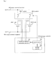
- Figure 1 is a diagram showing an exemplary embodiment of a discharge controller of the present invention.
- the present exemplary embodiment includes discharge controller 100, cells 300-1 and 300-2, switches 400-1 and 400-2, output terminal (positive) 500 and output terminal (negative) 501.
- Cells 300-1 and 300-2 are lithium-ion cells connected in parallel with each other. Negative electrode sides of cells 300-1 and 300-2 are connected to output terminal (negative) 501. Positive electrode sides of cells 300-1 and 300-2 are connected to switches 400-1 and 400-2, respectively, via discharge controller 100.
- the number of cells connected in parallel with each other is not limited to two.
- Switches 400-1 and 400-2 are switches to be closed/opened to establish or break connections between cells 300-1 and 300-2 and output terminal (positive) 500 through which cells 300-1 and 300-2 are externally discharged. This closing/opening is controlled by discharge controller 100.
- the number of switches is the same as the number of cells.
- Discharge controller 100 controls discharge of cells 300-1 and 300-2 by controlling closing/opening of switches 400-1 and 400-2 based on remaining capacities of cells 300-1 and 300-2.
- remaining capacity calculation section 110 In discharge controller 100, remaining capacity calculation section 110, storage section 120 and control section 130 are provided, as shown in Figure 1 .
- Remaining capacity calculation section 110 calculates remaining capacities of cells 300-1 and 300-2. Remaining capacity calculation section 110 calculates, as remaining capacities, values which are the results of subtraction of values obtained by measuring currents flowing from cells 300-1 and 300-2 and the time from a start of discharge of cells 300-1 and 300-2 and by multiplying the measured currents and time from the full-charge capacities of cells 300-1 and 300-2.
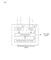
- Figure 2 is a diagram showing an example of an internal configuration of remaining capacity calculation section 110 shown in Figure 1 .
- ammeters 111-1 and 111-2, full-charge capacity hold section 112 and calculation section 113 are provided, as shown in Figure 2 .
- Ammeter 111-1 measures a current flowing from cell 300-1. Ammeter 111-1 outputs the measured current value of cell 300-1 to calculation section 113.
- Ammeter 111-2 measures a current flowing from cell 300-2. Ammeter 111-2 outputs the measured current value of cell 300-2 to calculation section 113.
- Full-charge capacity hold section 112 stores in advance the capacities of cells 300-1 and 300-2 when the capacities are fully charged.
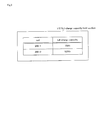
- Figure 3 is a diagram showing an example of the full-charge capacity stored in full-charge capacity hold section 112 shown in Figure 2 .
- cell 300-1 and a full-charge capacity 10 Ah are stored while being associated with each other. This indicates that the capacity of cell 300-1, when the cell is fully charged, is 10 Ah.
- cell 300-2 and a full-charge capacity 9.6 Ah are stored while being associated with each other. This indicates that the capacity of cell 300-2 when the cell is fully charged is 9.6 Ah.
- Calculation section 113 calculates remaining capacities of cells 300-1 and 300-2 based on the current values output from ammeters 111-1 and 111-2 and the full-charge capacities stored in full-charge capacity hold section 112.
- calculation section 113 multiplies the current value output from ammeter 111-1 and the time from a start of discharge (measured with a timer (not illustrated)) together and subtracts the product of multiplication from the full-charge capacity associated with cell 300-1 in full-charge capacity hold section 112 (10 Ah in the example shown in Figure 3 ). The value thereby obtained is the remaining capacity of cell 300-1.
- calculation section 113 multiplies the current value output from ammeter 111-2 and the time from the start of discharge (measured with the timer) together and subtracts the product of multiplication from the full-charge capacity associated with cell 300-2 in full-charge capacity hold section 112 (9.6 Ah in the example shown in Figure 3 ). The value thereby obtained is the remaining capacity of cell 300-2.
- Calculation section 113 outputs the calculated remaining capacities of cells 300-1 and 300-2 to control section 130.
- Storage section 120 stores a first threshold value and a second threshold value in advance.
- the first threshold value is the value at the upper side (upper limit) of the above-described “degradation region”.
- the second threshold value is the value at the lower side (lower limit) of the above-described "degradation region”.
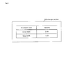
- Figure 4 is a diagram showing an example of threshold values stored in storage section 120 shown in Figure 1 .
- the upper limit and the lower limit of the degradation region are stored as threshold values, as shown in Figure 4 .
- 6 Ah is stored as a threshold value corresponding to the upper limit of the degradation region (first threshold value).
- 4 Ah is stored as a threshold value corresponding to the lower limit of the degradation region (second threshold value). This indicates that the range of remaining capacity of the cell from 6 Ah to 4 Ah is the degradation region.
- Control section 130 reads out the upper and lower limits of the degradation region stored in storage section 120, and compares the read upper and lower limits of the degradation region with the remaining capacities of cells 300-1 and 300-2 output from calculation section 113. If the remaining capacity of one of cells 300-1 and 300-2 is equal to the upper limit of the degradation region, control section 130 discharges only this cell until the remaining capacity of this cell becomes equal to the lower limit of the degradation region. At this time, priority may be giving discharging this cell. That is, in a case where three cells are connected in parallel with each other, the two-cell operation (discharge) of one of the cells whose remaining capacity is in the degradation region and one of the other two cells, two of these cells in all, may be performed.
- control section 130 maintains switch 400-1 in the closed state and maintains switch 400-2 in the open state until the remaining capacity of cell 300-1 becomes equal to the lower limit of the degradation region.
- control section 130 maintains switch 400-2 in the closed state and maintains switch 400-1 in the open state until the remaining capacity of cell 300-2 becomes equal to the lower limit of the degradation region.
- control section 130 may operate cells 300-1 and 300-2 in an ordinary two-cell parallel operation manner or may perform rotation discharge (discharge performed by control section 130 alternately repeating opening and closing of switches 400-1 and 400-2).
- control section 130 controls discharge and non-discharge of cells 300-1 and 300-2 by opening and closing switches 400-1 and 400-2.
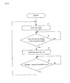
- Figure 5 is a flowchart showing a method of discharge control in the exemplary embodiment shown in Figure 1 .
- step 1 the two-cell operation (discharge) of cells 300-1 and 300-2 is started.
- discharge the above-described timer starts operating.
- control section 130 determines whether or not the remaining capacity of one of the cells is equal to the upper limit of the degradation region stored in storage section 120.
- This determination is realized by calculation in calculation section 113 multiplying together the current values measured and output by ammeters 111-1 and 111-2 and the time measured with the timer and subtracting the products of multiplication from the full-charge capacities of cells 300-1 and 300-2 stored in full-charge capacity hold section 112, and by comparing the results of subtraction with the upper limit of the degradation region stored as the first threshold value in storage section 120.
- the remaining capacity of cell 300-1 is 6.8 Ah from (Equation 1) and the upper limit of the degradation region stored in storage section 120 is 6 Ah, so that the remaining capacity of cell 300-1 and the upper limit of the degradation region are not equal to each other.
- the remaining capacity of cell 300-2 is 6 Ah from (Equation 2) and the upper limit of the degradation region stored in storage section 120 is 6 Ah, so that the remaining capacity of cell 300-2 and the upper limit of the degradation region are equal to each other.
- the cell whose remaining capacity is equal to the upper limit of the degradation region is cell 300-2.
- control section 130 does not determine in step 2 that the remaining capacity of one of the cells is equal to the upper limit of the degradation region, discharge of cells 300-1 and 300-2 is further continued.
- control section 130 determines in step 2 that the remaining capacity of one of the cells is equal to the upper limit of the degradation region, discharge of only the cell whose remaining capacity is equal to the upper limit of the degradation region is performed in step 3.
- Control section 130 performs this discharge control by using closing/opening of switches 400-1 and 400-2, as described above.
- control section 130 sets switch 400-1 in the open state. Cell 300-1 that is connected to switch 400-1 is not discharged thereafter. On the other hand, control section 130 sets switch 400-2 in the closed (connected) state. Discharge of cell 300-2 that is connected to switch 400-2 is performed thereby.
- control section 130 determines in step 4 whether or not the remaining capacity of the cell presently discharged is equal to the lower limit of the degradation region stored in storage section 120.
- the remaining capacity of cell 300-2 is calculated by remaining capacity calculation section 110, and the calculated remaining capacity and the lower limit of the degradation region stored in storage section 120 (4 Ah in the example shown in Figure 4 ) are compared.
- This remaining capacity calculation method uses the equation shown above.
- control section 130 does not determine in step 4 that the remaining capacity of the cell presently discharged is equal to the lower limit of the degradation region, that is, control section 130 determines that the remaining capacity of the cell presently discharged is not equal to the lower limit of the degradation region, discharge of this cell is further continued.
- discharge of only cell 300-2 since discharge of only cell 300-2 is performed, discharge of only cell 300-2 is continued if control section 130 determines that the remaining capacity of cell 300-2 is not equal to the lower limit of the degradation region.
- control section 130 determines in step 4 that the remaining capacity of the cell presently discharged is equal to the lower limit of the degradation region, processing in step 1 is performed.
- the two-cell operation (discharge) of cells 300-1 and 300-2 is performed (restarted) if control section 130 determines that the remaining capacity of cell 300-2 is equal to the lower limit of the degradation region.
- the remaining capacity of cell 300-1 also becomes equal to the upper limit of the degradation region stored in storage section 120. In that case, the same processing is also performed for discharge of only cell 300-1.
- Figure 6 is a diagram showing another exemplary embodiment of the discharge controller of the present invention.
- the present exemplary embodiment includes discharge controller 200, cells 300-1 and 300-2, switches 400-1 and 400-2, output terminal (positive) 500 and output terminal (negative) 501.
- Cells 300-1 and 300-2, switches 400-1 and 400-2, output terminal (positive) 500 and output terminal (negative) 501 are the same as those used in the exemplary embodiment shown in Figure 1 .
- the positive electrode side of cell 300-1 and switch 400-1 are directly connected to each other.
- the positive electrode side of cell 300-2 and switch 400-2 are directly connected to each other.
- Discharge controller 200 controls discharge of cells 300-1 and 300-2 by controlling closing/opening of switches 400-1 and 400-2 based on remaining capacities of cells 300-1 and 300-2.
- remaining capacity calculation section 210 In discharge controller 200, remaining capacity calculation section 210, storage section 220 and control section 230 are provided, as shown in Figure 6 .
- Remaining capacity calculation section 210 calculates remaining capacities of cells 300-1 and 300-2. Remaining capacity calculation section 210 calculates as remaining capacities the values of voltages across cells 300-1 and 300-2. Strictly speaking, in the case of using the voltage value as a remaining capacity as described above, the present resistance value is calculated from the present current and voltage values, and a voltage value estimated based on them by an open voltage method is calculated as the remaining capacity.
- Figure 7 is a diagram showing an example of an internal configuration of remaining capacity calculation section 210 shown in Figure 6 .
- voltmeters 211-1 and 211-2 are provided, as shown in Figure 7 .
- Voltmeter 211-1 measures the voltage across cell 300-1. Voltmeter 211-1 outputs the measured value of voltage across cell 300-1 to control section 230.
- Voltmeter 211-2 measures the voltage across cell 300-2. Voltmeter 211-2 outputs the measured value of voltage across cell 300-2 to control section 230.
- a method of calculating, when cells 300-1 and 300-2 shown in Figure 6 are discharged, remaining cell capacities, with respect to time, based upon changes in the values of voltages across cells 300-1 and 300-2 respectively measured by voltmeters 211-1 and 211-2 will be described below.
- a method of calculating a remaining capacity, with respect to time, based upon a change with respect to time in the value of voltage across cell 300-1 measured by voltmeter 211-1 when cell 300-1 is discharged will be described hereinbelow by way of example.
- a method of calculating a remaining capacity, with respect to time, based upon a change with respect to time in the value of voltage across cell 300-2 measured by voltmeter 211-2 when cell 300-2 is discharged is the same as the method of calculation with respect to cell 300-1.
- Figure 8 is a diagram showing an example of changes with respect to time in the value of voltage across cell 300-1 measured by voltmeter 211-1 when cell 300-1 shown in Figure 6 is discharged.
- the value of voltage across cell 300-1 measured by voltmeter 211-1 is lower than the actual capacity-dependent voltage indicated by the broken line because an external impedance, which is an external cause that is separate from the internal impedance of cell 300-1, is added as a causal resistance value (impedance) to the internal impedance of cell 300-1.
- the voltage value is estimated (corrected) by using the above-mentioned open voltage method.
- A shown in Figure 8 denotes a time at which discharge starts (point A)
- E shown in Figure 8 denotes a time at which discharge ends (point E).
- Point B is a point one second after point A
- point C is a point nine seconds after point B.
- a one-second average impedance between point A and point B is first calculated. Since the time period from point A to point B is one second, the impedance calculated at one point (point A) is the one-second average impedance between point A and point B. The calculated impedance is expressed as a ⁇ . This impedance a ⁇ is the sum of the internal impedance of the above-described cell 300-1 and the other external impedance.
- a one-second average impedance between point B and point C is thereafter calculated. Since the time period from point B to point C is nine seconds, impedance calculation is performed nine times at intervals of one second to obtain a one-second average value.
- the calculated impedance is expressed as b ⁇ . This b ⁇ is the internal impedance of the above-described cell 300-1.
- c ⁇ which is the external impedance
- impedance is calculated from the value of voltage across cell 300-1 measured by voltmeter 211-1.
- the voltage at point F can be obtained by adding the voltage drop that corresponds to b ⁇ from the calculated impedance at point E.
- Storage section 220 stores a first threshold value and a second threshold value in advance.
- the first threshold value is the value at the upper side (upper limit) of the above-described “degradation region”.
- the second threshold value is the value at the lower side (lower limit) of "the degradation region”.
- Figure 9 is a diagram showing an example of the threshold values stored in storage section 220 shown in Figure 6 .
- the upper limit and the lower limit are stored as threshold values in storage section 220 shown in Figure 6 .
- 2.4 V is stored as a threshold value corresponding to the upper limit of the degradation region (first threshold value).
- 1.6 V is stored as a threshold value corresponding to the lower limit of the degradation region (second threshold value). This indicates that the range of voltage value of the cell from 2.4 V to 1.6 V that corresponds to remaining capacities of the cell is the degradation region.
- Control section 230 reads out the upper and lower limits of the degradation region stored in storage section 220, and compares the read upper and lower limits of the degradation region with the voltage values output from voltmeters 211-1 and 211-2 as remaining capacities of cells 300-1 and 300-2. If the voltage value of one of cells 300-1 and 300-2 is equal to the upper limit of the degradation region, control section 230 discharges only this cell until the voltage value of this cell becomes equal to the lower limit of the degradation region.
- control section 230 maintains switch 400-1 in the closed state and maintains switch 400-2 in the open state until the voltage value of cell 300-1 becomes equal to the lower limit of the degradation region.
- control section 230 maintains switch 400-2 in the closed state and maintains switch 400-1 in the open state until the voltage value of cell 300-2 becomes equal to the lower limit of the degradation region.
- control section 230 may operate cells 300-1 and 300-2 in an ordinary two-cell parallel operation manner or may perform rotation discharge of cells 300-1 and 300-2.
- control section 230 may repeat alternately opening and closing switches 400-1 and 400-2.
- control section 230 controls discharge and non-discharge of cells 300-1 and 300-2 by opening and closing switches 400-1 and 400-2.
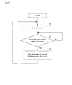
- Figure 10 is a flowchart showing a method of discharge control in the exemplary embodiment shown in Figure 6 .
- step 11 the two-cell operation (discharge) of cells 300-1 and 300-2 is started.
- control section 230 determines whether or not the voltage value of one of the cells measured by voltmeter 211-1 or 211-2 is equal to the upper limit of the degradation region stored in storage section 220.
- This determination is made based on the result comparing the voltage value measured by voltmeter 211-1 or 211-2 with the value equal to the upper limit of the degradation region stored in storage section 220.
- control section 230 determines that the voltage value of cell 300-1 measured by voltmeter 211-1 is equal to the upper limit of the degradation region.
- control section 230 does not determine in step 12 that the voltage value of one of the cells is equal to the upper limit of the degradation region, discharge of cells 300-1 and 300-2 is further continued.
- control section 230 determines in step 12 that the voltage value of one of the cells is equal to the upper limit of the degradation region, discharge of only the cell whose voltage value is equal to the upper limit of the degradation region is performed in step 13. Control section 230 performs this discharge control by using closing/opening of switches 400-1 and 400-2, as described above.
- control section 230 sets switch 400-2 in the open state. Cell 300-2 that is connected to switch 400-2 is not discharged thereafter. On the other hand, control section 230 sets switch 400-1 in the closed (connected) state. Discharge of cell 300-1 that is connected to switch 400-1 is performed thereby.
- control section 230 determines in step 14 whether or not the voltage value of the cell presently discharged is equal to the lower limit of the degradation region stored in the storage section 220.
- control section 230 determines that the voltage value of the cell presently discharged is not equal to the lower limit of the degradation region, discharge of this cell is further continued. Since discharge of only cell 300-1 is performed in the above-described example, discharge of only cell 300-1 is continued if control section 230 determines that the voltage value of cell 300-1 that is measured by voltmeter 211-1 is not equal to the lower limit of the degradation region.
- control section 230 determines in step 14 that the voltage value of the cell presently discharged is equal to the lower limit of the degradation region, processing in step 11 is performed. Since discharge of only cell 300-1 is performed in the above-described example, the two-cell operation (discharge) of cells 300-1 and 300-2 is performed (restarted) if control section 230 determines that the voltage value of cell 300-1 that is measured by voltmeter 211-1 is equal to the lower limit of the degradation region.
- the voltage value of cell 300-2 measured by voltmeter 211-2 also becomes equal to the upper limit of the degradation region stored in storage section 220. In that case, the same processing is also performed for discharge of only cell 300-2.
- Figure 11 is a graph showing change in remaining capacity of an ordinary cell with respect to time as the cell is discharged.
- Figure 12 is a graph showing an example of change in remaining capacity of a cell with respect to time as the cell is discharged according to the present invention.
- the degradation region passage time is reduced to 1/3 in a case where three cells are connected in parallel with each other, and the degradation region passage time is reduced to 1/4 in a case where four cells are connected in parallel with each other.
- the above-described method of calculating the remaining capacity of the cell is not exclusively used.
- Figure 13 is a diagram showing another exemplary embodiment of the discharge controller of the present invention.
- the present exemplary embodiment includes discharge controller 600, cells 300-1 and 300-2, switches 400-1 and 400-2, output terminal (positive) 500 and output terminal (negative) 501.
- Cells 300-1 and 300-2, switches 400-1 and 400-2, output terminal (positive) 500 and output terminal (negative) 501 are the same as those used in the exemplary embodiment shown in Figure 6 .
- the positive electrode side of cell 300-1 and switch 400-1 are directly connected to each other as in the exemplary embodiment shown in Figure 6 .
- the positive electrode side of cell 300-2 and switch 400-2 are directly connected to each other.
- Discharge controller 600 controls discharge of cells 300-1 and 300-2 by controlling closing/opening of switches 400-1 and 400-2 based on remaining capacities of cells 300-1 and 300-2.
- remaining capacity calculation section 210 In discharge controller 600, remaining capacity calculation section 210, storage section 620 and control section 630 are provided, as shown in Figure 13 .
- Remaining capacity calculation section 210 is the same as that shown in Figure 6 (the internal configuration is the same as that shown in Figure 7 ).
- Storage section 620 stores a threshold value in advance.
- the threshold value stored in storage section 620 is a value larger by a predetermined value than the value at the upper side (upper limit) of the above-described "degradation region”. That is, this threshold value is stored as a value on the verge of the "degradation region".
- Figure 14 is a diagram showing an example of the threshold value stored in storage section 620 shown in Figure 13 .
- a threshold value is stored in storage section 620 shown in Figure 13 .
- 2.4 V is stored as the threshold value (capacity), as shown in Figure 14 . This indicates that when the voltage value of the cell, or a remaining capacity of the cell, reaches 2.4 V, it also reaches a value on the border of the degradation region.
- Control section 630 reads out the threshold value stored in storage section 620 after starting discharge of cells 300-1 and 300-2, and compares the read threshold value and the voltage values output from voltmeters 211-1 and 211-2 as remaining capacities of cells 300-1 and 300-2. Control section 630 stops discharge of the first cell from cells 300-1 and 300-2 whose voltage value becomes equal to the threshold value. At this time, control section 630 continues discharge of the other cell - cell 300-1 or cell 300-2 - whose voltage value has not become equal to the threshold value.
- control section 630 sets switch 400-1 in the open state while maintaining switch 400-2 in the closed state.
- control section 630 sets switch 400-2 in the open state while maintaining switch 400-1 in the open state.
- Control section 630 may operate cells 300-1 and 300-2 in an ordinary two-cell parallel operation manner or may perform rotation discharge of cells 300-1 and 300-2 when the voltage value of cell 300-1 and the voltage value of cell 300-2 are each not equal to the threshold value. Specifically, in such a case, control section 630 may alternately perform opening and closing of switches 400-1 and 400-2.
- control section 630 controls discharge and non-discharge of cells 300-1 and 300-2 by opening and closing switches 400-1 and 400-2.
- Figure 15 is a flowchart showing a method of discharge control in the exemplary embodiment shown in Figure 13 .
- step 21 the two-cell operation (discharge) of cells 300-1 and 300-2 is started.
- control section 630 determines whether or not the voltage value of one of the cells measured by voltmeter 211-1 or 211-2 is equal to the threshold value stored in storage section 620.
- This determination is made based on the result of comparing the voltage value measured by voltmeter 211-1 or 211-2 with the threshold value stored in storage section 620.
- This voltage value may be a value calculated by using the above-described open voltage method.
- control section 630 determines that the voltage value of cell 300-1 measured by voltmeter 211-1 is equal to the threshold value.
- control section 630 does not determine in step 22 that the voltage value of one of the cells is equal to the threshold value, that is, the remaining capacities of cells 300-1 and 300-2 are each larger than the threshold value, discharge of cells 300-1 and 300-2 is continued.
- control section 630 determines in step 22 that the voltage value of one of the cells is equal to the threshold value, it stops discharge of the cell whose voltage value is equal to the threshold value, and only discharge of the other cell is performed in step 23. Control section 630 performs this discharge control by using closing/opening of switches 400-1 and 400-2, as described above.
- control section 630 sets switch 400-1 in the open state. Cell 300-1 that is connected to switch 400-1 is not discharged thereafter. On the other hand, control section 630 maintains switch 400-2 in the closed (connected) state. Discharge of cell 300-2 that is connected to switch 400-2 is continued thereby.
- the voltage value of cell 300-2 measured by voltmeter 211-2 also becomes equal to the threshold value stored in storage section 620. In that case, discharge of cell 300-2 is also stopped.
- the method of calculating the remaining capacity of the cell is not limited to that described above.
- a method using (full-charge capacity) - (current value) x (discharge time), as described above with reference to Figures 1 to 5 may alternatively be used.
- Processing operations performed by the components provided in the above-described discharge controller 100 or 200 may be performed by logic circuits made according to the purpose. Also, a program in which details of the processing operations are described may be recorded on a recording medium readable in discharge controller 100 or 200, and the program recorded on this recording medium may be read by discharge controller 100 or 200 to be executed.
- "Recording medium readable in discharge controller 100 or 200" denotes a removable recording medium such as a floppy (trademark) disk, a magneto-optical disk, a DVD or a CD, or a memory such as a ROM or a RAM, an HDD or the like incorporated in discharge controller 100 or 200.
- the program recorded on this recording medium is read by a CPU (not shown in the drawings) provided in discharge controller 100 or 200 and processing operations similar to those described above are performed under the control of the CPU.
- the CPU operates as a computer to execute the program read from the recording medium on which the program is recorded.
Landscapes
- Engineering & Computer Science (AREA)
- Power Engineering (AREA)
- Manufacturing & Machinery (AREA)
- Chemical & Material Sciences (AREA)
- Chemical Kinetics & Catalysis (AREA)
- Electrochemistry (AREA)
- General Chemical & Material Sciences (AREA)
- Secondary Cells (AREA)
- Charge And Discharge Circuits For Batteries Or The Like (AREA)
- Battery Mounting, Suspending (AREA)
Abstract
Description
- The present invention relates to a discharge controller, a discharge control method and a program for controlling discharge of cells.
- In recent years, in various fields, there have been growing concerns about environmental problems.
- With these concerns, in the field of electric power supply therein, certain approaches to power supply such as photovoltaic (PV) power generation and use of secondary cells used in electric vehicles (EVs) and hybrid EVs (HEVs) have attracted attention. Lithium-ion secondary cells are considered promising in such secondary cells. It is expected that lead storage cells will be replaced with Lithium-ion secondary cells in response to widespread use thereof in the future.
- As a rule, connecting an old cell (having a small discharge capacity) and a new cell (having a large discharge capacity) in parallel with each other should be avoided. This is for the purpose of avoiding a cross current caused by a difference between the voltages of the cells. A large cross current can cause excess current or abnormal heat generation. The same can also be said with respect to the above-described secondary cells.
- A system has therefore been devised in which respective switches for making connection/disconnection are provided for a plurality of cells connected in parallel with each other, and a switch that is provided only for the cell that has a higher voltage than that of the other cells is connected (maintained in the on state) at the time of discharge until the differences between the voltages of the cells become equal to or smaller than a predetermined value (see, for example, Patent Literature 1).
-
- Patent Literature 1:
JP2009-033936A - In recent years, a "degradation region" in which degradation of a cell is promoted in an intermediate region of a lithium-ion cell such as described above (the region from the upper limit to the lower limit of the discharge capacity in which the cell can supply power) has been discovered. Such a degradation region is noticeably recognized in lithium-ion cells having manganese-based positive electrodes in particular. Degradation of a cell is promoted by passage through the degradation region if a substantial length of time is taken to pass through the degradation region while the discharge capacity remaining in the cell is being reduced by discharge of the cell. It is, therefore, best to prohibit passage through this region to ensure long life for the cell. In a case where passage through the degradation region is required, however, there is a need to complete passage through the degradation region as fast as possible. There is the risk that degradation of a plurality of cells connected in parallel with each other will be particularly pronounced due to the low rate of reduction in discharge capacity for each cell.
- Even when the technique described in
Patent Literature 1 is used, an extension of the life of the cell cannot be achieved since discharge considering this degradation region cannot be performed. - An object of the present invention is to provide a discharge controller, a discharge control method and a program as a solution to the above-described problem.
- A discharge controller according to the present invention is a discharge controller for controlling discharge of a plurality of cells connected in parallel with each other, the controller including:
- a remaining capacity calculation section that calculates remaining capacities for each of the plurality of cells; and
- a control section that, after starting discharge of the plurality of cells, stops discharge of one of the cells whose remaining capacity calculated by the remaining capacity calculation section has become equal to a threshold value set in advance.
- A discharge control method according to the present invention is a discharge control method for controlling discharge of a plurality of cells connected in parallel with each other, the method including the steps of:
- discharging the plurality of cells;
- calculating remaining capacities for each of the plurality of cells; and
- stopping, after starting discharge of the plurality of cells, discharge of one of the plurality of cells whose remaining capacity calculated has become equal to a threshold value set in advance.
- A program according to the present invention is a program for making a controller that controls discharge of a plurality of cells connected in parallel with each other execute a process that consists of the steps of:
- discharging the plurality of cells;
- calculating remaining capacities for each of the plurality of cells; and
- stopping, after starting discharge of the plurality of cells, discharge of one of the plurality of cells whose remaining capacity calculated has become equal to a threshold value set in advance.
- As described above, according to the present invention, extension of the life of cells can be achieved.
-
-
Figure 1 is a diagram showing an exemplary embodiment of a discharge controller of the present invention. -
Figure 2 is a diagram showing an example of an internal configuration of a remaining capacity calculation section shown inFigure 1 . -
Figure 3 is a diagram showing an example of a full-charge capacity stored in a full-charge capacity hold section shown inFigure 2 . -
Figure 4 is a diagram showing an example of threshold values stored in a storage section shown inFigure 1 . -
Figure 5 is a flowchart for explaining a method of discharge control in the exemplary embodiment shown inFigure 1 . -
Figure 6 is a diagram showing another exemplary embodiment of the discharge controller of the present invention. -
Figure 7 is a diagram showing an example of an internal configuration of a remaining capacity calculation section shown inFigure 6 . -
Figure 8 is a diagram showing an example of changes with respect to time in the value of voltage across a cell shown inFigure 6 measured by a voltmeter when the cell is discharged. -
Figure 9 is a diagram showing an example of threshold values stored in a storage section shown inFigure 6 . -
Figure 10 is a flowchart for explaining a method of discharge control in the exemplary embodiment shown inFigure 6 . -
Figure 11 is a graph showing change in remaining capacity of an ordinary cell with respect to time as the cell is discharged. -
Figure 12 is a graph showing an example of change in remaining capacity of a cell with respect to time as the cell is discharged according to the present invention. -
Figure 13 is a diagram showing still another exemplary embodiment of the discharge controller of the present invention. - [Figure
Figure 14 is a diagram showing an example of threshold values stored in a storage section shown inFigure 13 . -
Figure 15 is a flowchart for explaining a method of discharge control in the exemplary embodiment shown inFigure 13 . - Exemplary embodiments will be described below with reference to the drawings.
-
Figure 1 is a diagram showing an exemplary embodiment of a discharge controller of the present invention. - As shown in
Figure 1 , the present exemplary embodiment includesdischarge controller 100, cells 300-1 and 300-2, switches 400-1 and 400-2, output terminal (positive) 500 and output terminal (negative) 501. - Cells 300-1 and 300-2 are lithium-ion cells connected in parallel with each other. Negative electrode sides of cells 300-1 and 300-2 are connected to output terminal (negative) 501. Positive electrode sides of cells 300-1 and 300-2 are connected to switches 400-1 and 400-2, respectively, via
discharge controller 100. The number of cells connected in parallel with each other is not limited to two. - Switches 400-1 and 400-2 are switches to be closed/opened to establish or break connections between cells 300-1 and 300-2 and output terminal (positive) 500 through which cells 300-1 and 300-2 are externally discharged. This closing/opening is controlled by
discharge controller 100. The number of switches is the same as the number of cells. -
Discharge controller 100 controls discharge of cells 300-1 and 300-2 by controlling closing/opening of switches 400-1 and 400-2 based on remaining capacities of cells 300-1 and 300-2. - In
discharge controller 100, remainingcapacity calculation section 110,storage section 120 andcontrol section 130 are provided, as shown inFigure 1 . - Remaining
capacity calculation section 110 calculates remaining capacities of cells 300-1 and 300-2. Remainingcapacity calculation section 110 calculates, as remaining capacities, values which are the results of subtraction of values obtained by measuring currents flowing from cells 300-1 and 300-2 and the time from a start of discharge of cells 300-1 and 300-2 and by multiplying the measured currents and time from the full-charge capacities of cells 300-1 and 300-2. -
Figure 2 is a diagram showing an example of an internal configuration of remainingcapacity calculation section 110 shown inFigure 1 . - In remaining
capacity calculation section 110 shown inFigure 1 , ammeters 111-1 and 111-2, full-chargecapacity hold section 112 andcalculation section 113 are provided, as shown inFigure 2 . - Ammeter 111-1 measures a current flowing from cell 300-1. Ammeter 111-1 outputs the measured current value of cell 300-1 to
calculation section 113. - Ammeter 111-2 measures a current flowing from cell 300-2. Ammeter 111-2 outputs the measured current value of cell 300-2 to
calculation section 113. - Full-charge
capacity hold section 112 stores in advance the capacities of cells 300-1 and 300-2 when the capacities are fully charged. -
Figure 3 is a diagram showing an example of the full-charge capacity stored in full-chargecapacity hold section 112 shown inFigure 2 . - In the full-charge
capacity hold section 112 shown inFigure 2 , the capacities of cells 300-1 and 300-2 when the cells are fully charged are stored as full-charge capacities, as shown inFigure 3 . This information is written in advance. - For example, as shown in
Figure 3 , cell 300-1 and a full-charge capacity 10 Ah are stored while being associated with each other. This indicates that the capacity of cell 300-1, when the cell is fully charged, is 10 Ah. - Also, as shown in
Figure 3 , cell 300-2 and a full-charge capacity 9.6 Ah are stored while being associated with each other. This indicates that the capacity of cell 300-2 when the cell is fully charged is 9.6 Ah. -
Calculation section 113 calculates remaining capacities of cells 300-1 and 300-2 based on the current values output from ammeters 111-1 and 111-2 and the full-charge capacities stored in full-chargecapacity hold section 112. - A concrete calculation method will be described below.
- With respect to a remaining capacity of cell 300-1,
calculation section 113 multiplies the current value output from ammeter 111-1 and the time from a start of discharge (measured with a timer (not illustrated)) together and subtracts the product of multiplication from the full-charge capacity associated with cell 300-1 in full-charge capacity hold section 112 (10 Ah in the example shown inFigure 3 ). The value thereby obtained is the remaining capacity of cell 300-1. - With respect to the remaining capacity of cell 300-2,
calculation section 113 multiplies the current value output from ammeter 111-2 and the time from the start of discharge (measured with the timer) together and subtracts the product of multiplication from the full-charge capacity associated with cell 300-2 in full-charge capacity hold section 112 (9.6 Ah in the example shown inFigure 3 ). The value thereby obtained is the remaining capacity of cell 300-2. -
Calculation section 113 outputs the calculated remaining capacities of cells 300-1 and 300-2 to controlsection 130. -
Storage section 120 stores a first threshold value and a second threshold value in advance. - The first threshold value is the value at the upper side (upper limit) of the above-described "degradation region". The second threshold value is the value at the lower side (lower limit) of the above-described "degradation region".
-
Figure 4 is a diagram showing an example of threshold values stored instorage section 120 shown inFigure 1 . - In
storage section 120 shown inFigure 1 , the upper limit and the lower limit of the degradation region are stored as threshold values, as shown inFigure 4 . - For example, as shown in
Figure 4 ,6 Ah is stored as a threshold value corresponding to the upper limit of the degradation region (first threshold value). Also, 4 Ah is stored as a threshold value corresponding to the lower limit of the degradation region (second threshold value). This indicates that the range of remaining capacity of the cell from 6 Ah to 4 Ah is the degradation region. -
Control section 130 reads out the upper and lower limits of the degradation region stored instorage section 120, and compares the read upper and lower limits of the degradation region with the remaining capacities of cells 300-1 and 300-2 output fromcalculation section 113. If the remaining capacity of one of cells 300-1 and 300-2 is equal to the upper limit of the degradation region,control section 130 discharges only this cell until the remaining capacity of this cell becomes equal to the lower limit of the degradation region. At this time, priority may be giving discharging this cell. That is, in a case where three cells are connected in parallel with each other, the two-cell operation (discharge) of one of the cells whose remaining capacity is in the degradation region and one of the other two cells, two of these cells in all, may be performed. - For example, if the remaining capacity of cell 300-1 becomes equal to the upper limit of the degradation region,
control section 130 maintains switch 400-1 in the closed state and maintains switch 400-2 in the open state until the remaining capacity of cell 300-1 becomes equal to the lower limit of the degradation region. - If the remaining capacity of cell 300-2 becomes equal to the upper limit of the degradation region,
control section 130 maintains switch 400-2 in the closed state and maintains switch 400-1 in the open state until the remaining capacity of cell 300-2 becomes equal to the lower limit of the degradation region. - When the remaining capacity of cell 300-1 and the remaining capacity of cell 300-2 is out of the range from the upper limit to the lower limit of the degradation region, that is, when each remaining capacity is not in the degradation region,
control section 130 may operate cells 300-1 and 300-2 in an ordinary two-cell parallel operation manner or may perform rotation discharge (discharge performed bycontrol section 130 alternately repeating opening and closing of switches 400-1 and 400-2). - Thus,
control section 130 controls discharge and non-discharge of cells 300-1 and 300-2 by opening and closing switches 400-1 and 400-2. - A method of discharge control in the exemplary embodiment shown in
Figure 1 will be described below. -
Figure 5 is a flowchart showing a method of discharge control in the exemplary embodiment shown inFigure 1 . - First, in
step 1, the two-cell operation (discharge) of cells 300-1 and 300-2 is started. When discharge is started, the above-described timer starts operating. - When discharge is started, measurement of the currents flowing from cells 300-1 and 300-2 by ammeters 111-1 and 111-2 is started.
- Thereafter, in
step 2,control section 130 determines whether or not the remaining capacity of one of the cells is equal to the upper limit of the degradation region stored instorage section 120. - This determination is realized by calculation in
calculation section 113 multiplying together the current values measured and output by ammeters 111-1 and 111-2 and the time measured with the timer and subtracting the products of multiplication from the full-charge capacities of cells 300-1 and 300-2 stored in full-chargecapacity hold section 112, and by comparing the results of subtraction with the upper limit of the degradation region stored as the first threshold value instorage section 120. - Description will be made concretely by way of example with respect to a case where, for example, the full-charge capacities of cells 300-1 and 300-2 stored in full-charge
capacity hold section 112 have the values shown inFigure 3 (10 Ah and 9.6 Ah); the upper limit of the degradation region (first threshold value) stored instorage section 120 is the value shown inFigure 4 , i.e., 6 Ah; and the lower limit of the degradation region (second threshold value) is the value shown inFigure 4 , i.e., 4 Ah. - In a case where when the timer measures two hours, the current value measured and output by ammeter 111-1 is 1.6 A and the current value measured and output by ammeter 111-2 is 1.8 A, calculations described below are performed.
- A calculation by (Equation 1) is made with respect to cell 300-1.
-

A calculation by (Equation 2) is made with respect to cell 300-2. - 9.6 Ah (full-charge capacity) - 1.8 A (current value) x 2h (hours) = 6 Ah (remaining capacity) (Equation 2)
The remaining capacities calculated with respect to cells 300-1 and 300-2 are compared with the upper limit of the degradation region stored instorage section 120. - The remaining capacity of cell 300-1 is 6.8 Ah from (Equation 1) and the upper limit of the degradation region stored in
storage section 120 is 6 Ah, so that the remaining capacity of cell 300-1 and the upper limit of the degradation region are not equal to each other. - On the other hand, the remaining capacity of cell 300-2 is 6 Ah from (Equation 2) and the upper limit of the degradation region stored in
storage section 120 is 6 Ah, so that the remaining capacity of cell 300-2 and the upper limit of the degradation region are equal to each other. - As a result, the cell whose remaining capacity is equal to the upper limit of the degradation region is cell 300-2.
- If
control section 130 does not determine instep 2 that the remaining capacity of one of the cells is equal to the upper limit of the degradation region, discharge of cells 300-1 and 300-2 is further continued. - On the other hand, if
control section 130 determines instep 2 that the remaining capacity of one of the cells is equal to the upper limit of the degradation region, discharge of only the cell whose remaining capacity is equal to the upper limit of the degradation region is performed instep 3.Control section 130 performs this discharge control by using closing/opening of switches 400-1 and 400-2, as described above. - In the above-described example (the case where cell 300-2 is the cell whose remaining capacity became equal to the upper limit of the degradation region),
control section 130 sets switch 400-1 in the open state. Cell 300-1 that is connected to switch 400-1 is not discharged thereafter. On the other hand,control section 130 sets switch 400-2 in the closed (connected) state. Discharge of cell 300-2 that is connected to switch 400-2 is performed thereby. - Thereafter,
control section 130 determines instep 4 whether or not the remaining capacity of the cell presently discharged is equal to the lower limit of the degradation region stored instorage section 120. - In the above-described example (discharge of only cell 300-2 is performed), the remaining capacity of cell 300-2 is calculated by remaining
capacity calculation section 110, and the calculated remaining capacity and the lower limit of the degradation region stored in storage section 120 (4 Ah in the example shown inFigure 4 ) are compared. This remaining capacity calculation method uses the equation shown above. - If
control section 130 does not determine instep 4 that the remaining capacity of the cell presently discharged is equal to the lower limit of the degradation region, that is,control section 130 determines that the remaining capacity of the cell presently discharged is not equal to the lower limit of the degradation region, discharge of this cell is further continued. In the above-described example, since discharge of only cell 300-2 is performed, discharge of only cell 300-2 is continued ifcontrol section 130 determines that the remaining capacity of cell 300-2 is not equal to the lower limit of the degradation region. - On the other hand, if
control section 130 determines instep 4 that the remaining capacity of the cell presently discharged is equal to the lower limit of the degradation region, processing instep 1 is performed. In the above-described example, since discharge of only cell 300-2 is performed, the two-cell operation (discharge) of cells 300-1 and 300-2 is performed (restarted) ifcontrol section 130 determines that the remaining capacity of cell 300-2 is equal to the lower limit of the degradation region. - Thereafter, the remaining capacity of cell 300-1 also becomes equal to the upper limit of the degradation region stored in
storage section 120. In that case, the same processing is also performed for discharge of only cell 300-1. - A case where (full-charge capacity) - (current value) x (discharge time), as described by using (Equation 1) and (Equation 2), is used as the remaining capacity of each cell has been described. However, the value of voltage across each cell may alternatively be used.
-
Figure 6 is a diagram showing another exemplary embodiment of the discharge controller of the present invention. - As shown in
Figure 6 , the present exemplary embodiment includesdischarge controller 200, cells 300-1 and 300-2, switches 400-1 and 400-2, output terminal (positive) 500 and output terminal (negative) 501. - Cells 300-1 and 300-2, switches 400-1 and 400-2, output terminal (positive) 500 and output terminal (negative) 501 are the same as those used in the exemplary embodiment shown in
Figure 1 . In the present exemplary embodiment, the positive electrode side of cell 300-1 and switch 400-1 are directly connected to each other. Also, the positive electrode side of cell 300-2 and switch 400-2 are directly connected to each other. -
Discharge controller 200 controls discharge of cells 300-1 and 300-2 by controlling closing/opening of switches 400-1 and 400-2 based on remaining capacities of cells 300-1 and 300-2. - In
discharge controller 200, remainingcapacity calculation section 210,storage section 220 andcontrol section 230 are provided, as shown inFigure 6 . - Remaining
capacity calculation section 210 calculates remaining capacities of cells 300-1 and 300-2. Remainingcapacity calculation section 210 calculates as remaining capacities the values of voltages across cells 300-1 and 300-2. Strictly speaking, in the case of using the voltage value as a remaining capacity as described above, the present resistance value is calculated from the present current and voltage values, and a voltage value estimated based on them by an open voltage method is calculated as the remaining capacity. -
Figure 7 is a diagram showing an example of an internal configuration of remainingcapacity calculation section 210 shown inFigure 6 . - In remaining
capacity calculation section 210 shown inFigure 6 , voltmeters 211-1 and 211-2 are provided, as shown inFigure 7 . - Voltmeter 211-1 measures the voltage across cell 300-1. Voltmeter 211-1 outputs the measured value of voltage across cell 300-1 to control
section 230. - Voltmeter 211-2 measures the voltage across cell 300-2. Voltmeter 211-2 outputs the measured value of voltage across cell 300-2 to control
section 230. - A method of calculating, when cells 300-1 and 300-2 shown in
Figure 6 are discharged, remaining cell capacities, with respect to time, based upon changes in the values of voltages across cells 300-1 and 300-2 respectively measured by voltmeters 211-1 and 211-2 will be described below. A method of calculating a remaining capacity, with respect to time, based upon a change with respect to time in the value of voltage across cell 300-1 measured by voltmeter 211-1 when cell 300-1 is discharged will be described hereinbelow by way of example. A method of calculating a remaining capacity, with respect to time, based upon a change with respect to time in the value of voltage across cell 300-2 measured by voltmeter 211-2 when cell 300-2 is discharged is the same as the method of calculation with respect to cell 300-1. -
Figure 8 is a diagram showing an example of changes with respect to time in the value of voltage across cell 300-1 measured by voltmeter 211-1 when cell 300-1 shown inFigure 6 is discharged. - As shown in
Figure 8 , the value of voltage across cell 300-1 measured by voltmeter 211-1 ("actual discharge voltage" indicated by the solid line inFigure 8 ) is lower than the actual capacity-dependent voltage indicated by the broken line because an external impedance, which is an external cause that is separate from the internal impedance of cell 300-1, is added as a causal resistance value (impedance) to the internal impedance of cell 300-1. - Therefore, the voltage value is estimated (corrected) by using the above-mentioned open voltage method.
- "A" shown in
Figure 8 denotes a time at which discharge starts (point A), and "E" shown inFigure 8 denotes a time at which discharge ends (point E). Point B is a point one second after point A, and point C is a point nine seconds after point B. - A one-second average impedance between point A and point B is first calculated. Since the time period from point A to point B is one second, the impedance calculated at one point (point A) is the one-second average impedance between point A and point B. The calculated impedance is expressed as a Ω. This impedance a Ω is the sum of the internal impedance of the above-described cell 300-1 and the other external impedance.
- A one-second average impedance between point B and point C is thereafter calculated. Since the time period from point B to point C is nine seconds, impedance calculation is performed nine times at intervals of one second to obtain a one-second average value. The calculated impedance is expressed as b Ω. This b Ω is the internal impedance of the above-described cell 300-1.
- Therefore, c Ω, which is the external impedance, can be calculated by subtracting b Ω from a Ω (a - b = c).
- Thereafter, as discharge end point E is being reached, a one-second average impedance for one second (between point D and point F) and a one-second average impedance for nine seconds (between point F and point G) are also calculated.
- At point E, impedance is calculated from the value of voltage across cell 300-1 measured by voltmeter 211-1. The voltage at point F can be obtained by adding the voltage drop that corresponds to b Ω from the calculated impedance at point E.
- Subsequently, the actual capacity-dependent voltage (remaining capacity) can be calculated by adding the external impedance c Ω to the average of the one-second average impedance between point D and point F (1D Ω) and the one-second average impedance between point F and point G (9D Ω), and by multiplying the value obtained by this addition by the current value (I). That is, if the remaining capacity is CAPV,

If the value of the external impedance c Ω is set in advance, it may be used. Remainingcapacity calculation section 210 may calculate remaining capacities of cells 300-1 and 300-2 in this way. -
Storage section 220 stores a first threshold value and a second threshold value in advance. - The first threshold value is the value at the upper side (upper limit) of the above-described "degradation region". The second threshold value is the value at the lower side (lower limit) of "the degradation region".
-
Figure 9 is a diagram showing an example of the threshold values stored instorage section 220 shown inFigure 6 . - As shown in
Figure 9 , the upper limit and the lower limit are stored as threshold values instorage section 220 shown inFigure 6 . - For example, as shown in
Figure 9 , 2.4 V is stored as a threshold value corresponding to the upper limit of the degradation region (first threshold value). Also, 1.6 V is stored as a threshold value corresponding to the lower limit of the degradation region (second threshold value). This indicates that the range of voltage value of the cell from 2.4 V to 1.6 V that corresponds to remaining capacities of the cell is the degradation region. -
Control section 230 reads out the upper and lower limits of the degradation region stored instorage section 220, and compares the read upper and lower limits of the degradation region with the voltage values output from voltmeters 211-1 and 211-2 as remaining capacities of cells 300-1 and 300-2. If the voltage value of one of cells 300-1 and 300-2 is equal to the upper limit of the degradation region,control section 230 discharges only this cell until the voltage value of this cell becomes equal to the lower limit of the degradation region. - For example, if the voltage value of cell 300-1 becomes equal to the upper limit of the degradation region,
control section 230 maintains switch 400-1 in the closed state and maintains switch 400-2 in the open state until the voltage value of cell 300-1 becomes equal to the lower limit of the degradation region. - If the voltage value of cell 300-2 becomes equal to the upper limit of the degradation region,
control section 230 maintains switch 400-2 in the closed state and maintains switch 400-1 in the open state until the voltage value of cell 300-2 becomes equal to the lower limit of the degradation region. - When the voltage value of cell 300-1 and the voltage value of cell 300-2 are out of the range from the upper limit to the lower limit of the degradation region, that is, each voltage value is not in the degradation region,
control section 230 may operate cells 300-1 and 300-2 in an ordinary two-cell parallel operation manner or may perform rotation discharge of cells 300-1 and 300-2. - Specifically, in such a case,
control section 230 may repeat alternately opening and closing switches 400-1 and 400-2. - Thus,
control section 230 controls discharge and non-discharge of cells 300-1 and 300-2 by opening and closing switches 400-1 and 400-2. - A method of discharge control in the exemplary embodiment shown in
Figure 6 will be described below. -
Figure 10 is a flowchart showing a method of discharge control in the exemplary embodiment shown inFigure 6 . - First, in
step 11, the two-cell operation (discharge) of cells 300-1 and 300-2 is started. - When discharge is started, measurement of the values of voltages across cells 300-1 and 300-2 by voltmeters 211-1 and 211-2 is started.
- Thereafter, in
step 12,control section 230 determines whether or not the voltage value of one of the cells measured by voltmeter 211-1 or 211-2 is equal to the upper limit of the degradation region stored instorage section 220. - This determination is made based on the result comparing the voltage value measured by voltmeter 211-1 or 211-2 with the value equal to the upper limit of the degradation region stored in
storage section 220. - For example, in a case where threshold values that corresponds to the upper limit (2.4 V) and the lower limit (1.6 V) of the degradation region as shown in
Figure 9 are stored instorage section 220, if the voltage value measured by voltmeter 211-1 is 2.4 V, and if the voltage value measured by voltmeter 211-2 is 2.5 V,control section 230 determines that the voltage value of cell 300-1 measured by voltmeter 211-1 is equal to the upper limit of the degradation region. - If
control section 230 does not determine instep 12 that the voltage value of one of the cells is equal to the upper limit of the degradation region, discharge of cells 300-1 and 300-2 is further continued. - On the other hand, if
control section 230 determines instep 12 that the voltage value of one of the cells is equal to the upper limit of the degradation region, discharge of only the cell whose voltage value is equal to the upper limit of the degradation region is performed instep 13.Control section 230 performs this discharge control by using closing/opening of switches 400-1 and 400-2, as described above. - In the above-described example (the case where cell 300-1 is the cell whose voltage value became equal to the upper limit of the degradation region),
control section 230 sets switch 400-2 in the open state. Cell 300-2 that is connected to switch 400-2 is not discharged thereafter. On the other hand,control section 230 sets switch 400-1 in the closed (connected) state. Discharge of cell 300-1 that is connected to switch 400-1 is performed thereby. - Thereafter,
control section 230 determines instep 14 whether or not the voltage value of the cell presently discharged is equal to the lower limit of the degradation region stored in thestorage section 220. - In the above-described example (discharge of only cell 300-1 is performed), the voltage value of cell 300-1 measured by voltmeter 211-1 and the lower limit of the degradation region stored in storage section 220 (1.6 V in the example shown in
Figure 9 ) are compared. - If
control section 230 does not determine instep 14 that the voltage value of the cell presently discharged is equal to the lower limit of the degradation region, that is,control section 230 determines that the voltage value of the cell presently discharged is not equal to the lower limit of the degradation region, discharge of this cell is further continued. Since discharge of only cell 300-1 is performed in the above-described example, discharge of only cell 300-1 is continued ifcontrol section 230 determines that the voltage value of cell 300-1 that is measured by voltmeter 211-1 is not equal to the lower limit of the degradation region. - If
control section 230 determines instep 14 that the voltage value of the cell presently discharged is equal to the lower limit of the degradation region, processing instep 11 is performed. Since discharge of only cell 300-1 is performed in the above-described example, the two-cell operation (discharge) of cells 300-1 and 300-2 is performed (restarted) ifcontrol section 230 determines that the voltage value of cell 300-1 that is measured by voltmeter 211-1 is equal to the lower limit of the degradation region. - Thereafter, the voltage value of cell 300-2 measured by voltmeter 211-2 also becomes equal to the upper limit of the degradation region stored in
storage section 220. In that case, the same processing is also performed for discharge of only cell 300-2. - As described above, only the cell whose remaining capacity has entered the degradation region during discharge of the plurality of cells that are connected in parallel with each other is discharged, thus enabling fast passage through the degradation region. This effect will be described below with reference to the drawings. A case where two cells are connected in parallel with each other will be described below by way of example.
-
Figure 11 is a graph showing change in remaining capacity of an ordinary cell with respect to time as the cell is discharged. -
Figure 12 is a graph showing an example of change in remaining capacity of a cell with respect to time as the cell is discharged according to the present invention. - In ordinary cases, as shown in
Figure 11 , the remaining capacity of a cell decreases at a generally constant rate with respect to discharge time. The time period taken for passage through the degradation region from a capacity of 6 Ah to a capacity of 4 Ah is assumed to be Ta. - On the other hand, as shown in
Figure 12 , since discharge of only one cell is performed from the remaining capacity 6A that corresponds to the upper limit of the degradation region to 4 Ah, the rate of reduction in remaining capacity of the cell with respect to time in the degradation region is increased. That is, the time taken for passage through the degradation region in discharge of the cell is reduced. As shown inFigure 12 , in the case described here by way of example, where two cells are connected in parallel with each other, the time taken for passage through the degradation region is reduced to Ta/2, i.e., to half of the time in the case shown inFigure 11 . - Needless to say, the degradation region passage time is reduced to 1/3 in a case where three cells are connected in parallel with each other, and the degradation region passage time is reduced to 1/4 in a case where four cells are connected in parallel with each other.
- The above-described method of calculating the remaining capacity of the cell is not exclusively used.
- Thus, when a cell has a remaining capacity in a degradation region by discharge, the time taken for passage through the degradation region can be reduced by discharging only this cell. As a result, an extension of the life of the cell can be achieved. This effect is particularly high when discharge control is performed on lithium-ion cells that have manganese-based positive poles in which a degradation region is noticeably recognized.
- While a process in which when a cell has a remaining capacity in a degradation region by discharge, only this cell is discharged has been described, a process may alternatively be performed in which discharge of one of cells having a remaining capacity immediately before its reaching the degradation region is stopped while discharge of the other cells is performed.
-
Figure 13 is a diagram showing another exemplary embodiment of the discharge controller of the present invention. - As shown in
Figure 13 , the present exemplary embodiment includesdischarge controller 600, cells 300-1 and 300-2, switches 400-1 and 400-2, output terminal (positive) 500 and output terminal (negative) 501. - Cells 300-1 and 300-2, switches 400-1 and 400-2, output terminal (positive) 500 and output terminal (negative) 501 are the same as those used in the exemplary embodiment shown in
Figure 6 . In the present exemplary embodiment, the positive electrode side of cell 300-1 and switch 400-1 are directly connected to each other as in the exemplary embodiment shown inFigure 6 . Also, the positive electrode side of cell 300-2 and switch 400-2 are directly connected to each other. -
Discharge controller 600 controls discharge of cells 300-1 and 300-2 by controlling closing/opening of switches 400-1 and 400-2 based on remaining capacities of cells 300-1 and 300-2. - In
discharge controller 600, remainingcapacity calculation section 210,storage section 620 andcontrol section 630 are provided, as shown inFigure 13 . - Remaining
capacity calculation section 210 is the same as that shown inFigure 6 (the internal configuration is the same as that shown inFigure 7 ). -
Storage section 620 stores a threshold value in advance. - The threshold value stored in
storage section 620 is a value larger by a predetermined value than the value at the upper side (upper limit) of the above-described "degradation region". That is, this threshold value is stored as a value on the verge of the "degradation region". -
Figure 14 is a diagram showing an example of the threshold value stored instorage section 620 shown inFigure 13 . - As shown in
Figure 14 , a threshold value is stored instorage section 620 shown inFigure 13 . - For example, 2.4 V is stored as the threshold value (capacity), as shown in
Figure 14 . This indicates that when the voltage value of the cell, or a remaining capacity of the cell, reaches 2.4 V, it also reaches a value on the border of the degradation region. -
Control section 630 reads out the threshold value stored instorage section 620 after starting discharge of cells 300-1 and 300-2, and compares the read threshold value and the voltage values output from voltmeters 211-1 and 211-2 as remaining capacities of cells 300-1 and 300-2.Control section 630 stops discharge of the first cell from cells 300-1 and 300-2 whose voltage value becomes equal to the threshold value. At this time,control section 630 continues discharge of the other cell - cell 300-1 or cell 300-2 - whose voltage value has not become equal to the threshold value. - For example, when the voltage value of cell 300-1 becomes equal to the threshold value after
control section 630 has started discharge by closing switches 400-1 and 400-2,control section 630 sets switch 400-1 in the open state while maintaining switch 400-2 in the closed state. - When the voltage value of cell 300-2 thereafter becomes equal to the threshold value,
control section 630 sets switch 400-2 in the open state while maintaining switch 400-1 in the open state. -
Control section 630 may operate cells 300-1 and 300-2 in an ordinary two-cell parallel operation manner or may perform rotation discharge of cells 300-1 and 300-2 when the voltage value of cell 300-1 and the voltage value of cell 300-2 are each not equal to the threshold value. Specifically, in such a case,control section 630 may alternately perform opening and closing of switches 400-1 and 400-2. - Thus,
control section 630 controls discharge and non-discharge of cells 300-1 and 300-2 by opening and closing switches 400-1 and 400-2. - A method of discharge control in the exemplary embodiment shown in
Figure 13 will be described below. -
Figure 15 is a flowchart showing a method of discharge control in the exemplary embodiment shown inFigure 13 . - First, in
step 21, the two-cell operation (discharge) of cells 300-1 and 300-2 is started. - When discharge is started, measurement of the values of voltages across cells 300-1 and 300-2 by voltmeters 211-1 and 211-2 is started.
- Thereafter, in
step 22,control section 630 determines whether or not the voltage value of one of the cells measured by voltmeter 211-1 or 211-2 is equal to the threshold value stored instorage section 620. - This determination is made based on the result of comparing the voltage value measured by voltmeter 211-1 or 211-2 with the threshold value stored in
storage section 620. This voltage value may be a value calculated by using the above-described open voltage method. - For example, in a case where a threshold value (2.4 V) such as shown in
Figure 14 is stored instorage section 620, if the voltage value measured by voltmeter 211-1 is 2.4 V while the voltage value measured by voltmeter 211-2 is 2.5 V,control section 630 determines that the voltage value of cell 300-1 measured by voltmeter 211-1 is equal to the threshold value. - If
control section 630 does not determine instep 22 that the voltage value of one of the cells is equal to the threshold value, that is, the remaining capacities of cells 300-1 and 300-2 are each larger than the threshold value, discharge of cells 300-1 and 300-2 is continued. - On the other hand, if
control section 630 determines instep 22 that the voltage value of one of the cells is equal to the threshold value, it stops discharge of the cell whose voltage value is equal to the threshold value, and only discharge of the other cell is performed instep 23.Control section 630 performs this discharge control by using closing/opening of switches 400-1 and 400-2, as described above. - In the above-described example (the case where cell 300-1 is the cell whose voltage value became equal to the threshold value),
control section 630 sets switch 400-1 in the open state. Cell 300-1 that is connected to switch 400-1 is not discharged thereafter. On the other hand,control section 630 maintains switch 400-2 in the closed (connected) state. Discharge of cell 300-2 that is connected to switch 400-2 is continued thereby. - Thereafter, the voltage value of cell 300-2 measured by voltmeter 211-2 also becomes equal to the threshold value stored in
storage section 620. In that case, discharge of cell 300-2 is also stopped. - As described above, in the course of discharging a plurality of cells connected in parallel with each other, discharge of one of the cells whose remaining capacity becomes equal to a value on the border of the degradation region is stopped, thus enabling avoiding passage of the cell through the degradation region.
- The method of calculating the remaining capacity of the cell is not limited to that described above. For example, a method using (full-charge capacity) - (current value) x (discharge time), as described above with reference to
Figures 1 to 5 , may alternatively be used. - Thus, when the remaining capacity of a cell approaches the degradation region, discharge of the cell is stopped. Passage through the degradation region can be avoided by stopping discharge of the cell. As a result, extension of the cell life can be achieved. This effect is particularly high when discharge control is performed on lithium-ion cells that have manganese-based positive poles in which a degradation region is noticeably recognized.
- Easily understandable numeric values including capacities have been used in the above text or the drawings for ease of description. Not all of them are the same as the actual values.
- Processing operations performed by the components provided in the above-described
discharge controller discharge controller discharge controller discharge controller discharge controller discharge controller - The invention of the present application has been described by referring to the exemplary embodiments. However, the invention of the present application is not limited to the above-described exemplary embodiments. Various changes and modifications understandable by those skilled in the art can be made to the configuration and details of the invention of the present application within the scope of the invention of the present application.
- This application is based upon and claims the benefit of priority from the prior Japanese Application No.
2010-287837 filed on December 24, 2010
Claims (14)
- A discharge controller for controlling discharge of a plurality of cells connected in parallel with each other, the controller comprising:a remaining capacity calculation section that calculates remaining capacities for each of the plurality of cells; anda control section that, after starting discharge of the plurality of cells, stops discharge of one of the cells whose remaining capacity calculated by said remaining capacity calculation section has become equal to a threshold value set in advance.
- The discharge controller according to Claim 1, wherein said remaining capacity calculation section measures currents flowing from the cells and the time from the start of discharge of the cells, and obtains, as the remaining capacities, values calculated by respectively subtracting the products of multiplication of the measured currents and time from the full-charge capacities of the cells.
- The discharge controller according to Claim 1, wherein said remaining capacity calculation section measures voltages across the cells and obtains the measured voltages as the remaining capacities.
- The discharge controller according to Claim 1, further comprising a storage section that stores the threshold value in advance,
wherein said control section reads out the threshold value stored in said storage section and compares the threshold values with the remaining capacities. - The discharge controller according to Claim 1, wherein said control section controls discharge and non-discharge of the plurality of cells by opening and closing a plurality of switches for establishing or breaking connections between the plurality of cells and an output terminal through which cells are externally discharged.
- The discharge controller according to Claim 1, wherein said control section performs rotation discharge of the plurality of cells if each of the remaining capacities of the plurality of cells is larger than the threshold value.
- A discharge control method for controlling discharge of a plurality of cells connected in parallel with each other, the method comprising the steps of:discharging the plurality of cells;calculating remaining capacities for each of the plurality of cells; andstopping, after starting discharge of the plurality of cells, discharge of one of the plurality of cells whose remaining capacity calculated has become equal to a threshold value set in advance.
- The discharge control method according to Claim 7, wherein said calculation step includes measuring currents flowing from the cells and the time from the start of discharge of the cells, and obtaining, as the remaining capacities, values calculated by respectively subtracting the products of multiplication of the measured currents and time from the full-charge capacities of the cells.
- The discharge control method according to Claim 7, wherein said calculation step includes measuring voltages across the cells and obtaining the measured voltages as the remaining capacities.
- The discharge control method according to Claim 7, further comprising the step of performing rotation discharge of the plurality of cells if each of the remaining capacities of the plurality of cells is larger than the threshold value.
- A program for making a controller that controls discharge of a plurality of cells connected in parallel with each other execute a process that consists of the steps of:discharging the plurality of cells;calculating remaining capacities for each of the plurality of cells; andstopping, after starting discharge of the plurality of cells, discharge of one of the plurality of cells whose remaining capacity calculated has become equal to a threshold value set in advance.
- The program according to Claim 11, wherein said calculation process step includes measuring currents flowing from the cells and the time from the start of discharge of the cells, and obtaining, as the remaining capacities, values calculated by respectively subtracting the products of multiplication of the measured currents and time from the full-charge capacities of the cells.
- The program according to Claim 11, wherein said calculation process step includes measuring voltages across the cells and obtaining the measured voltages as the remaining capacities.
- The program according to Claim 11 of executing a process consisting of the step of performing rotation discharge of the plurality of cells if each of the remaining capacities of the plurality of cells is larger than the threshold value.
Applications Claiming Priority (2)
| Application Number | Priority Date | Filing Date | Title |
|---|---|---|---|
| JP2010287837A JP2012138981A (en) | 2010-12-24 | 2010-12-24 | Discharge controller, discharge control method, and program |
| PCT/JP2011/077353 WO2012086369A1 (en) | 2010-12-24 | 2011-11-28 | Discharge controller |
Publications (3)
| Publication Number | Publication Date |
|---|---|
| EP2658076A1 true EP2658076A1 (en) | 2013-10-30 |
| EP2658076A4 EP2658076A4 (en) | 2018-02-14 |
| EP2658076B1 EP2658076B1 (en) | 2020-11-11 |
Family
ID=46313651
Family Applications (1)
| Application Number | Title | Priority Date | Filing Date |
|---|---|---|---|
| EP11851038.7A Active EP2658076B1 (en) | 2010-12-24 | 2011-11-28 | Discharge controller |
Country Status (5)
| Country | Link |
|---|---|
| US (1) | US20130265008A1 (en) |
| EP (1) | EP2658076B1 (en) |
| JP (1) | JP2012138981A (en) |
| CN (1) | CN103262381B (en) |
| WO (1) | WO2012086369A1 (en) |
Cited By (1)
| Publication number | Priority date | Publication date | Assignee | Title |
|---|---|---|---|---|
| EP2816701A4 (en) * | 2012-02-16 | 2015-10-28 | Nec Corp | ADJUSTING DEVICE, BATTERY ASSEMBLY, AND ADJUSTING METHOD |
Families Citing this family (1)
| Publication number | Priority date | Publication date | Assignee | Title |
|---|---|---|---|---|
| US10522881B1 (en) * | 2018-01-12 | 2019-12-31 | Cora Aero Llc | Estimation of self discharge rate as a measure of battery health |
Family Cites Families (13)
| Publication number | Priority date | Publication date | Assignee | Title |
|---|---|---|---|---|
| JPS62181632A (en) * | 1986-01-31 | 1987-08-10 | 日本電気株式会社 | Battery saving circuit |
| JP3580123B2 (en) * | 1998-03-20 | 2004-10-20 | 富士通株式会社 | Battery device |
| JP5045156B2 (en) * | 2007-03-09 | 2012-10-10 | 株式会社日立製作所 | Charge / discharge control device and railway vehicle using the same |
| JP5017009B2 (en) | 2007-07-30 | 2012-09-05 | 株式会社東芝 | Parallel connection power storage system |
| JP5376364B2 (en) * | 2008-03-07 | 2013-12-25 | 公立大学法人首都大学東京 | Solid electrolyte structure manufacturing method, all solid state battery manufacturing method, solid electrolyte structure and all solid state battery |
| JP2009240078A (en) * | 2008-03-27 | 2009-10-15 | Yokogawa Electric Corp | Power supply controller |
| JP5478870B2 (en) * | 2008-10-15 | 2014-04-23 | 三菱重工業株式会社 | Power storage system and power storage system |
| JP5371462B2 (en) * | 2009-02-04 | 2013-12-18 | 三菱重工業株式会社 | Power supply system and power supply method thereof |
| US20100213897A1 (en) * | 2009-02-23 | 2010-08-26 | Lawrence Tze-Leung Tse | Battery-Cell Converter Management Systems |
| JP4635094B2 (en) * | 2009-04-30 | 2011-02-16 | 株式会社東芝 | Information processing device |
| JP2010273519A (en) * | 2009-05-25 | 2010-12-02 | Nippon Telegr & Teleph Corp <Ntt> | Charge / discharge control method |
| JP5665285B2 (en) | 2009-06-15 | 2015-02-04 | 日立化成株式会社 | Optical semiconductor element mounting member and optical semiconductor device |
| CN102388499B (en) * | 2010-03-23 | 2014-06-18 | 日本电气株式会社 | Method for charging/discharging lithium-ion secondary battery, and charging/discharging system |
-
2010
- 2010-12-24 JP JP2010287837A patent/JP2012138981A/en active Pending
-
2011
- 2011-11-28 WO PCT/JP2011/077353 patent/WO2012086369A1/en not_active Ceased
- 2011-11-28 US US13/991,329 patent/US20130265008A1/en not_active Abandoned
- 2011-11-28 EP EP11851038.7A patent/EP2658076B1/en active Active
- 2011-11-28 CN CN201180062342.0A patent/CN103262381B/en active Active
Non-Patent Citations (1)
| Title |
|---|
| See references of WO2012086369A1 * |
Cited By (2)
| Publication number | Priority date | Publication date | Assignee | Title |
|---|---|---|---|---|
| EP2816701A4 (en) * | 2012-02-16 | 2015-10-28 | Nec Corp | ADJUSTING DEVICE, BATTERY ASSEMBLY, AND ADJUSTING METHOD |
| US9570923B2 (en) | 2012-02-16 | 2017-02-14 | Nec Corporation | Adjusting device, battery pack, and adjusting method |
Also Published As
| Publication number | Publication date |
|---|---|
| WO2012086369A1 (en) | 2012-06-28 |
| CN103262381B (en) | 2017-08-01 |
| CN103262381A (en) | 2013-08-21 |
| EP2658076A4 (en) | 2018-02-14 |
| EP2658076B1 (en) | 2020-11-11 |
| US20130265008A1 (en) | 2013-10-10 |
| JP2012138981A (en) | 2012-07-19 |
Similar Documents
| Publication | Publication Date | Title |
|---|---|---|
| EP3982140B1 (en) | Device for managing battery and method for managing battery | |
| KR102259967B1 (en) | Apparatus and method for managing charging of battery | |
| JP7145865B2 (en) | Rechargeable battery short-circuit prediction device and rechargeable battery short-circuit prediction method | |
| EP2690454B1 (en) | Device for measuring degradation, rechargeable battery pack, method for measuring degradation, and program | |
| CN101960691B (en) | Charging device and quality judging device of pack cell | |
| US20070222418A1 (en) | Method for Managing a Pool or Rechargeable Batteries | |
| JP2011520408A (en) | Method for detecting branch of cell charge and discharge states of series or group of batteries or capacitors | |
| EP3006946B1 (en) | Storage battery monitoring device | |
| CN111164824B (en) | Battery pack management device and battery pack system | |
| EP2658075A1 (en) | Discharge controller | |
| JP2020079764A (en) | Secondary battery status determination method | |
| CN104113101A (en) | Battery system with battery module and method for determining operating parameters | |
| KR100964316B1 (en) | Battery cell balancing system, method and recording medium recording the same | |
| Coleman et al. | State of health determination: Two pulse load test for a VRLA battery | |
| WO2022091673A1 (en) | Abnormality detection method, abnormality detection device, power storage device, and computer program | |
| EP2658076B1 (en) | Discharge controller | |
| EP2658074B1 (en) | Discharge controller | |
| JP2003243017A (en) | Electric equivalent circuit model forming method for secondary battery and simulation method and program using this | |
| US20120146589A1 (en) | Method and Device For Charging Lithium-Cobalt Cells | |
| Thakur et al. | State of Charge Estimation and Constant Current Constant Voltage Charging of Lithium Ion Battery for Electric Vehicle Applications | |
| US20260098909A1 (en) | Intelligent power management system and method for monitoring battery integrity | |
| CN119482863A (en) | Multi-battery charging method, device, power-consuming device, electronic device and storage medium | |
| Miller | Minimization of Circuitry in Large Format Lithium-ion Battery Management Systems |
Legal Events
| Date | Code | Title | Description |
|---|---|---|---|
| PUAI | Public reference made under article 153(3) epc to a published international application that has entered the european phase |
Free format text: ORIGINAL CODE: 0009012 |
|
| 17P | Request for examination filed |
Effective date: 20130710 |
|
| AK | Designated contracting states |
Kind code of ref document: A1 Designated state(s): AL AT BE BG CH CY CZ DE DK EE ES FI FR GB GR HR HU IE IS IT LI LT LU LV MC MK MT NL NO PL PT RO RS SE SI SK SM TR |
|
| DAX | Request for extension of the european patent (deleted) | ||
| RA4 | Supplementary search report drawn up and despatched (corrected) |
Effective date: 20180112 |
|
| RIC1 | Information provided on ipc code assigned before grant |
Ipc: H01M 2/10 20060101ALI20180108BHEP Ipc: H01M 10/48 20060101ALI20180108BHEP Ipc: H01M 10/44 20060101ALI20180108BHEP Ipc: H02J 7/00 20060101AFI20180108BHEP |
|
| STAA | Information on the status of an ep patent application or granted ep patent |
Free format text: STATUS: EXAMINATION IS IN PROGRESS |
|
| 17Q | First examination report despatched |
Effective date: 20190802 |
|
| RAP1 | Party data changed (applicant data changed or rights of an application transferred) |
Owner name: ENVISION AESC ENERGY DEVICES LTD. |
|
| GRAP | Despatch of communication of intention to grant a patent |
Free format text: ORIGINAL CODE: EPIDOSNIGR1 |
|
| STAA | Information on the status of an ep patent application or granted ep patent |
Free format text: STATUS: GRANT OF PATENT IS INTENDED |
|
| INTG | Intention to grant announced |
Effective date: 20200616 |
|
| GRAS | Grant fee paid |
Free format text: ORIGINAL CODE: EPIDOSNIGR3 |
|
| GRAA | (expected) grant |
Free format text: ORIGINAL CODE: 0009210 |
|
| STAA | Information on the status of an ep patent application or granted ep patent |
Free format text: STATUS: THE PATENT HAS BEEN GRANTED |
|
| AK | Designated contracting states |
Kind code of ref document: B1 Designated state(s): AL AT BE BG CH CY CZ DE DK EE ES FI FR GB GR HR HU IE IS IT LI LT LU LV MC MK MT NL NO PL PT RO RS SE SI SK SM TR |
|
| REG | Reference to a national code |
Ref country code: GB Ref legal event code: FG4D |
|
| REG | Reference to a national code |
Ref country code: CH Ref legal event code: EP |
|
| REG | Reference to a national code |
Ref country code: AT Ref legal event code: REF Ref document number: 1334369 Country of ref document: AT Kind code of ref document: T Effective date: 20201115 |
|
| REG | Reference to a national code |
Ref country code: DE Ref legal event code: R096 Ref document number: 602011069293 Country of ref document: DE |
|
| REG | Reference to a national code |
Ref country code: IE Ref legal event code: FG4D |
|
| REG | Reference to a national code |
Ref country code: NL Ref legal event code: MP Effective date: 20201111 |
|
| REG | Reference to a national code |
Ref country code: AT Ref legal event code: MK05 Ref document number: 1334369 Country of ref document: AT Kind code of ref document: T Effective date: 20201111 |
|
| PG25 | Lapsed in a contracting state [announced via postgrant information from national office to epo] |
Ref country code: FI Free format text: LAPSE BECAUSE OF FAILURE TO SUBMIT A TRANSLATION OF THE DESCRIPTION OR TO PAY THE FEE WITHIN THE PRESCRIBED TIME-LIMIT Effective date: 20201111 Ref country code: RS Free format text: LAPSE BECAUSE OF FAILURE TO SUBMIT A TRANSLATION OF THE DESCRIPTION OR TO PAY THE FEE WITHIN THE PRESCRIBED TIME-LIMIT Effective date: 20201111 Ref country code: NO Free format text: LAPSE BECAUSE OF FAILURE TO SUBMIT A TRANSLATION OF THE DESCRIPTION OR TO PAY THE FEE WITHIN THE PRESCRIBED TIME-LIMIT Effective date: 20210211 Ref country code: PT Free format text: LAPSE BECAUSE OF FAILURE TO SUBMIT A TRANSLATION OF THE DESCRIPTION OR TO PAY THE FEE WITHIN THE PRESCRIBED TIME-LIMIT Effective date: 20210311 Ref country code: GR Free format text: LAPSE BECAUSE OF FAILURE TO SUBMIT A TRANSLATION OF THE DESCRIPTION OR TO PAY THE FEE WITHIN THE PRESCRIBED TIME-LIMIT Effective date: 20210212 |
|
| PG25 | Lapsed in a contracting state [announced via postgrant information from national office to epo] |
Ref country code: AT Free format text: LAPSE BECAUSE OF FAILURE TO SUBMIT A TRANSLATION OF THE DESCRIPTION OR TO PAY THE FEE WITHIN THE PRESCRIBED TIME-LIMIT Effective date: 20201111 Ref country code: BG Free format text: LAPSE BECAUSE OF FAILURE TO SUBMIT A TRANSLATION OF THE DESCRIPTION OR TO PAY THE FEE WITHIN THE PRESCRIBED TIME-LIMIT Effective date: 20210211 Ref country code: IS Free format text: LAPSE BECAUSE OF FAILURE TO SUBMIT A TRANSLATION OF THE DESCRIPTION OR TO PAY THE FEE WITHIN THE PRESCRIBED TIME-LIMIT Effective date: 20210311 Ref country code: LV Free format text: LAPSE BECAUSE OF FAILURE TO SUBMIT A TRANSLATION OF THE DESCRIPTION OR TO PAY THE FEE WITHIN THE PRESCRIBED TIME-LIMIT Effective date: 20201111 Ref country code: PL Free format text: LAPSE BECAUSE OF FAILURE TO SUBMIT A TRANSLATION OF THE DESCRIPTION OR TO PAY THE FEE WITHIN THE PRESCRIBED TIME-LIMIT Effective date: 20201111 Ref country code: SE Free format text: LAPSE BECAUSE OF FAILURE TO SUBMIT A TRANSLATION OF THE DESCRIPTION OR TO PAY THE FEE WITHIN THE PRESCRIBED TIME-LIMIT Effective date: 20201111 |
|
| REG | Reference to a national code |
Ref country code: LT Ref legal event code: MG9D |
|
| PG25 | Lapsed in a contracting state [announced via postgrant information from national office to epo] |
Ref country code: HR Free format text: LAPSE BECAUSE OF FAILURE TO SUBMIT A TRANSLATION OF THE DESCRIPTION OR TO PAY THE FEE WITHIN THE PRESCRIBED TIME-LIMIT Effective date: 20201111 |
|
| REG | Reference to a national code |
Ref country code: CH Ref legal event code: PL |
|
| PG25 | Lapsed in a contracting state [announced via postgrant information from national office to epo] |
Ref country code: LT Free format text: LAPSE BECAUSE OF FAILURE TO SUBMIT A TRANSLATION OF THE DESCRIPTION OR TO PAY THE FEE WITHIN THE PRESCRIBED TIME-LIMIT Effective date: 20201111 Ref country code: SK Free format text: LAPSE BECAUSE OF FAILURE TO SUBMIT A TRANSLATION OF THE DESCRIPTION OR TO PAY THE FEE WITHIN THE PRESCRIBED TIME-LIMIT Effective date: 20201111 Ref country code: RO Free format text: LAPSE BECAUSE OF FAILURE TO SUBMIT A TRANSLATION OF THE DESCRIPTION OR TO PAY THE FEE WITHIN THE PRESCRIBED TIME-LIMIT Effective date: 20201111 Ref country code: SM Free format text: LAPSE BECAUSE OF FAILURE TO SUBMIT A TRANSLATION OF THE DESCRIPTION OR TO PAY THE FEE WITHIN THE PRESCRIBED TIME-LIMIT Effective date: 20201111 Ref country code: EE Free format text: LAPSE BECAUSE OF FAILURE TO SUBMIT A TRANSLATION OF THE DESCRIPTION OR TO PAY THE FEE WITHIN THE PRESCRIBED TIME-LIMIT Effective date: 20201111 Ref country code: CZ Free format text: LAPSE BECAUSE OF FAILURE TO SUBMIT A TRANSLATION OF THE DESCRIPTION OR TO PAY THE FEE WITHIN THE PRESCRIBED TIME-LIMIT Effective date: 20201111 Ref country code: LU Free format text: LAPSE BECAUSE OF NON-PAYMENT OF DUE FEES Effective date: 20201128 |
|
| REG | Reference to a national code |
Ref country code: BE Ref legal event code: MM Effective date: 20201130 |
|
| REG | Reference to a national code |
Ref country code: DE Ref legal event code: R097 Ref document number: 602011069293 Country of ref document: DE |
|
| PG25 | Lapsed in a contracting state [announced via postgrant information from national office to epo] |
Ref country code: LI Free format text: LAPSE BECAUSE OF NON-PAYMENT OF DUE FEES Effective date: 20201130 Ref country code: CH Free format text: LAPSE BECAUSE OF NON-PAYMENT OF DUE FEES Effective date: 20201130 Ref country code: DK Free format text: LAPSE BECAUSE OF FAILURE TO SUBMIT A TRANSLATION OF THE DESCRIPTION OR TO PAY THE FEE WITHIN THE PRESCRIBED TIME-LIMIT Effective date: 20201111 Ref country code: MC Free format text: LAPSE BECAUSE OF FAILURE TO SUBMIT A TRANSLATION OF THE DESCRIPTION OR TO PAY THE FEE WITHIN THE PRESCRIBED TIME-LIMIT Effective date: 20201111 |
|
| PLBE | No opposition filed within time limit |
Free format text: ORIGINAL CODE: 0009261 |
|
| STAA | Information on the status of an ep patent application or granted ep patent |
Free format text: STATUS: NO OPPOSITION FILED WITHIN TIME LIMIT |
|
| 26N | No opposition filed |
Effective date: 20210812 |
|
| PG25 | Lapsed in a contracting state [announced via postgrant information from national office to epo] |
Ref country code: AL Free format text: LAPSE BECAUSE OF FAILURE TO SUBMIT A TRANSLATION OF THE DESCRIPTION OR TO PAY THE FEE WITHIN THE PRESCRIBED TIME-LIMIT Effective date: 20201111 Ref country code: IE Free format text: LAPSE BECAUSE OF NON-PAYMENT OF DUE FEES Effective date: 20201128 Ref country code: IT Free format text: LAPSE BECAUSE OF FAILURE TO SUBMIT A TRANSLATION OF THE DESCRIPTION OR TO PAY THE FEE WITHIN THE PRESCRIBED TIME-LIMIT Effective date: 20201111 Ref country code: NL Free format text: LAPSE BECAUSE OF FAILURE TO SUBMIT A TRANSLATION OF THE DESCRIPTION OR TO PAY THE FEE WITHIN THE PRESCRIBED TIME-LIMIT Effective date: 20201111 |
|
| PG25 | Lapsed in a contracting state [announced via postgrant information from national office to epo] |
Ref country code: ES Free format text: LAPSE BECAUSE OF FAILURE TO SUBMIT A TRANSLATION OF THE DESCRIPTION OR TO PAY THE FEE WITHIN THE PRESCRIBED TIME-LIMIT Effective date: 20201111 Ref country code: SI Free format text: LAPSE BECAUSE OF FAILURE TO SUBMIT A TRANSLATION OF THE DESCRIPTION OR TO PAY THE FEE WITHIN THE PRESCRIBED TIME-LIMIT Effective date: 20201111 |
|
| PG25 | Lapsed in a contracting state [announced via postgrant information from national office to epo] |
Ref country code: IS Free format text: LAPSE BECAUSE OF FAILURE TO SUBMIT A TRANSLATION OF THE DESCRIPTION OR TO PAY THE FEE WITHIN THE PRESCRIBED TIME-LIMIT Effective date: 20210311 Ref country code: TR Free format text: LAPSE BECAUSE OF FAILURE TO SUBMIT A TRANSLATION OF THE DESCRIPTION OR TO PAY THE FEE WITHIN THE PRESCRIBED TIME-LIMIT Effective date: 20201111 Ref country code: MT Free format text: LAPSE BECAUSE OF FAILURE TO SUBMIT A TRANSLATION OF THE DESCRIPTION OR TO PAY THE FEE WITHIN THE PRESCRIBED TIME-LIMIT Effective date: 20201111 Ref country code: CY Free format text: LAPSE BECAUSE OF FAILURE TO SUBMIT A TRANSLATION OF THE DESCRIPTION OR TO PAY THE FEE WITHIN THE PRESCRIBED TIME-LIMIT Effective date: 20201111 |
|
| PG25 | Lapsed in a contracting state [announced via postgrant information from national office to epo] |
Ref country code: MK Free format text: LAPSE BECAUSE OF FAILURE TO SUBMIT A TRANSLATION OF THE DESCRIPTION OR TO PAY THE FEE WITHIN THE PRESCRIBED TIME-LIMIT Effective date: 20201111 |
|
| PG25 | Lapsed in a contracting state [announced via postgrant information from national office to epo] |
Ref country code: BE Free format text: LAPSE BECAUSE OF NON-PAYMENT OF DUE FEES Effective date: 20201130 |
|
| P01 | Opt-out of the competence of the unified patent court (upc) registered |
Effective date: 20230517 |
|
| PGFP | Annual fee paid to national office [announced via postgrant information from national office to epo] |
Ref country code: FR Payment date: 20250930 Year of fee payment: 15 |
|
| PGFP | Annual fee paid to national office [announced via postgrant information from national office to epo] |
Ref country code: DE Payment date: 20250930 Year of fee payment: 15 |
|
| PGFP | Annual fee paid to national office [announced via postgrant information from national office to epo] |
Ref country code: GB Payment date: 20251001 Year of fee payment: 15 |