EP2658072A2 - System for contactless transfer of energy and data and vehicle with such a system - Google Patents
System for contactless transfer of energy and data and vehicle with such a system Download PDFInfo
- Publication number
- EP2658072A2 EP2658072A2 EP13165568.0A EP13165568A EP2658072A2 EP 2658072 A2 EP2658072 A2 EP 2658072A2 EP 13165568 A EP13165568 A EP 13165568A EP 2658072 A2 EP2658072 A2 EP 2658072A2
- Authority
- EP
- European Patent Office
- Prior art keywords
- alternating
- line
- frequency range
- filter
- primary
- Prior art date
- Legal status (The legal status is an assumption and is not a legal conclusion. Google has not performed a legal analysis and makes no representation as to the accuracy of the status listed.)
- Granted
Links
Images
Classifications
-
- H—ELECTRICITY
- H04—ELECTRIC COMMUNICATION TECHNIQUE
- H04B—TRANSMISSION
- H04B5/00—Near-field transmission systems, e.g. inductive or capacitive transmission systems
- H04B5/70—Near-field transmission systems, e.g. inductive or capacitive transmission systems specially adapted for specific purposes
- H04B5/79—Near-field transmission systems, e.g. inductive or capacitive transmission systems specially adapted for specific purposes for data transfer in combination with power transfer
-
- B—PERFORMING OPERATIONS; TRANSPORTING
- B60—VEHICLES IN GENERAL
- B60R—VEHICLES, VEHICLE FITTINGS, OR VEHICLE PARTS, NOT OTHERWISE PROVIDED FOR
- B60R16/00—Electric or fluid circuits specially adapted for vehicles and not otherwise provided for; Arrangement of elements of electric or fluid circuits specially adapted for vehicles and not otherwise provided for
- B60R16/02—Electric or fluid circuits specially adapted for vehicles and not otherwise provided for; Arrangement of elements of electric or fluid circuits specially adapted for vehicles and not otherwise provided for electric constitutive elements
- B60R16/023—Electric or fluid circuits specially adapted for vehicles and not otherwise provided for; Arrangement of elements of electric or fluid circuits specially adapted for vehicles and not otherwise provided for electric constitutive elements for transmission of signals between vehicle parts or subsystems
- B60R16/0239—Electronic boxes
-
- B—PERFORMING OPERATIONS; TRANSPORTING
- B60—VEHICLES IN GENERAL
- B60R—VEHICLES, VEHICLE FITTINGS, OR VEHICLE PARTS, NOT OTHERWISE PROVIDED FOR
- B60R16/00—Electric or fluid circuits specially adapted for vehicles and not otherwise provided for; Arrangement of elements of electric or fluid circuits specially adapted for vehicles and not otherwise provided for
- B60R16/02—Electric or fluid circuits specially adapted for vehicles and not otherwise provided for; Arrangement of elements of electric or fluid circuits specially adapted for vehicles and not otherwise provided for electric constitutive elements
- B60R16/023—Electric or fluid circuits specially adapted for vehicles and not otherwise provided for; Arrangement of elements of electric or fluid circuits specially adapted for vehicles and not otherwise provided for electric constitutive elements for transmission of signals between vehicle parts or subsystems
- B60R16/027—Electric or fluid circuits specially adapted for vehicles and not otherwise provided for; Arrangement of elements of electric or fluid circuits specially adapted for vehicles and not otherwise provided for electric constitutive elements for transmission of signals between vehicle parts or subsystems between relatively movable parts of the vehicle, e.g. between steering wheel and column
-
- H—ELECTRICITY
- H02—GENERATION; CONVERSION OR DISTRIBUTION OF ELECTRIC POWER
- H02J—ELECTRIC POWER NETWORKS; CIRCUIT ARRANGEMENTS OR SYSTEMS FOR SUPPLYING OR DISTRIBUTING ELECTRIC POWER; SYSTEMS FOR STORING ELECTRIC ENERGY
- H02J50/00—Circuit arrangements or systems for wireless supply or distribution of electric power
- H02J50/10—Circuit arrangements or systems for wireless supply or distribution of electric power using inductive coupling
-
- H—ELECTRICITY
- H02—GENERATION; CONVERSION OR DISTRIBUTION OF ELECTRIC POWER
- H02J—ELECTRIC POWER NETWORKS; CIRCUIT ARRANGEMENTS OR SYSTEMS FOR SUPPLYING OR DISTRIBUTING ELECTRIC POWER; SYSTEMS FOR STORING ELECTRIC ENERGY
- H02J50/00—Circuit arrangements or systems for wireless supply or distribution of electric power
- H02J50/80—Circuit arrangements or systems for wireless supply or distribution of electric power involving the exchange of data, concerning supply or distribution of electric power, between transmitting devices and receiving devices
-
- H—ELECTRICITY
- H04—ELECTRIC COMMUNICATION TECHNIQUE
- H04B—TRANSMISSION
- H04B5/00—Near-field transmission systems, e.g. inductive or capacitive transmission systems
- H04B5/20—Near-field transmission systems, e.g. inductive or capacitive transmission systems characterised by the transmission technique; characterised by the transmission medium
- H04B5/24—Inductive coupling
-
- H—ELECTRICITY
- H04—ELECTRIC COMMUNICATION TECHNIQUE
- H04B—TRANSMISSION
- H04B5/00—Near-field transmission systems, e.g. inductive or capacitive transmission systems
- H04B5/20—Near-field transmission systems, e.g. inductive or capacitive transmission systems characterised by the transmission technique; characterised by the transmission medium
- H04B5/24—Inductive coupling
- H04B5/26—Inductive coupling using coils
- H04B5/266—One coil at each side, e.g. with primary and secondary coils
-
- B—PERFORMING OPERATIONS; TRANSPORTING
- B64—AIRCRAFT; AVIATION; COSMONAUTICS
- B64D—EQUIPMENT FOR FITTING IN OR TO AIRCRAFT; FLIGHT SUITS; PARACHUTES; ARRANGEMENT OR MOUNTING OF POWER PLANTS OR PROPULSION TRANSMISSIONS IN AIRCRAFT
- B64D11/00—Passenger or crew accommodation; Flight-deck installations not otherwise provided for
- B64D11/0015—Arrangements for entertainment or communications, e.g. radio, television
-
- B—PERFORMING OPERATIONS; TRANSPORTING
- B64—AIRCRAFT; AVIATION; COSMONAUTICS
- B64D—EQUIPMENT FOR FITTING IN OR TO AIRCRAFT; FLIGHT SUITS; PARACHUTES; ARRANGEMENT OR MOUNTING OF POWER PLANTS OR PROPULSION TRANSMISSIONS IN AIRCRAFT
- B64D2221/00—Electric power distribution systems onboard aircraft
-
- B—PERFORMING OPERATIONS; TRANSPORTING
- B64—AIRCRAFT; AVIATION; COSMONAUTICS
- B64D—EQUIPMENT FOR FITTING IN OR TO AIRCRAFT; FLIGHT SUITS; PARACHUTES; ARRANGEMENT OR MOUNTING OF POWER PLANTS OR PROPULSION TRANSMISSIONS IN AIRCRAFT
- B64D2231/00—Emergency oxygen systems
- B64D2231/02—Supply or distribution systems
- B64D2231/025—Oxygen masks; Mask storages; Features related to mask deployment
-
- H—ELECTRICITY
- H02—GENERATION; CONVERSION OR DISTRIBUTION OF ELECTRIC POWER
- H02J—ELECTRIC POWER NETWORKS; CIRCUIT ARRANGEMENTS OR SYSTEMS FOR SUPPLYING OR DISTRIBUTING ELECTRIC POWER; SYSTEMS FOR STORING ELECTRIC ENERGY
- H02J2105/00—Networks for supplying or distributing electric power characterised by their spatial reach or by the load
- H02J2105/30—Networks for supplying or distributing electric power characterised by their spatial reach or by the load the load networks being external to vehicles, i.e. exchanging power with vehicles
- H02J2105/32—Networks for supplying or distributing electric power characterised by their spatial reach or by the load the load networks being external to vehicles, i.e. exchanging power with vehicles for aircrafts
-
- H—ELECTRICITY
- H04—ELECTRIC COMMUNICATION TECHNIQUE
- H04B—TRANSMISSION
- H04B5/00—Near-field transmission systems, e.g. inductive or capacitive transmission systems
- H04B5/40—Near-field transmission systems, e.g. inductive or capacitive transmission systems characterised by components specially adapted for near-field transmission
Definitions
- the invention relates to a system for the contactless transfer of energy and data and to a vehicle with such a system.
- DALs design assurance levels
- DE 10 2008 024 217 A1 discloses a system for contactless energy and data transfer, in which system a transducer/transformer is formed between the first vehicle part and the second vehicle part. Apart from the transfer of energy, data is transferred as alternating-voltage signals that are modulated onto a carrier signal with a carrier frequency.
- the electrical connection of devices with stringent safety requirements, for example of release mechanisms of compartments for oxygen masks, on board commercial aircraft is usually implemented by separate cabling arrangements in order to achieve a high DAL level.
- devices in a passenger service unit (PSU) which devices are located above seats whose positions are variable, may be electrically connected, by means of a system for contactless energy and data transfer, to a higher-level system of the commercial aircraft. Since in a PSU the loudspeakers, lights or operating buttons have only relatively low application criticality, the contactless data and energy transfer system used for this may have a relatively low DAL level. However, this excludes the connection of critical devices, for example the release mechanisms for mask compartments, to such a system. However, adapting conventional cabling arrangements after reconfiguration of the cabin would result in additional cabling effort and expenditure.
- a system for the contactless transfer of energy and data comprises a transfer path with a primary coil, connected by way of a primary line to a primary control unit, and a secondary coil, connected by way of a secondary line to a secondary control unit, wherein the primary control unit is designed to lead data-modulated first alternating-voltage signals of a first frequency range into the primary coil, and the secondary control unit is designed to receive alternating-voltage signals of the first frequency range from the secondary coil, and to demodulate the modulated-on data.
- the system according to the invention further comprises a feed-in line connected to the primary line, an activation line connected to the secondary line, and a first filter arranged between the activation line and an activation connection, which first filter is permeable to second alternating-voltage signals of a second frequency range while blocking the first alternating-voltage signals of the first frequency range.
- a system for contactless energy and data transfer which system is for example known from DE 10 2008 024 217 A1 , may be modified to such an extent that despite the primary control units and secondary control units necessary for data transfer, which primary control units and secondary control units in a conventional design for use in non-critical functions have an inferior DAL level than do devices for critical functions, may nevertheless be used for the transfer of an additional signal or of an alternating voltage for controlling devices with significantly more critical safety requirements.
- the reliability of transfer of the second alternating-voltage signal is very high, because exclusively passive components are used that are technically mature and that preclude the occurrence of logic-related failures.
- the primary coil is preferably arranged in a vehicle-fixed or structure-fixed manner, i.e. in a fixed position within the vehicle, on a first vehicle part, thus forming a primary strand with the first connecting line and with the primary control unit, which primary strand is, for example, connected to a higher-level vehicle system.
- the first vehicle part may thus be a vehicle-fixed or structure-fixed component.
- the primary coil is arranged in a primary core that comprises any form suitable for forming a transducer/transformer with a secondary coil.
- the primary coil or the primary core should be positioned in such a manner that alignment of a secondary coil results in the formation of a transdurcer/transformer.
- the secondary coil may, furthermore, be arranged in a movable second vehicle part.
- Movability relates to the suitability of assuming various positions within the vehicle if required. This may apply in the context of reconfiguration of the passenger cabin, in which the seat pitch of passenger seats is changed in order to vary, even temporarily, the number of seats in various classes.
- the second vehicle part may, for example, comprise a PSU in a vehicle cabin, or may be connected to said PSU, wherein in order to achieve reconfigurability of a passenger cabin the PSU may be arranged above movable passenger seats, aligned with said passenger seats, at various positions on stowage compartment panels or cover panels.
- the devices contained therein are supplied with electrical power and data by way of the transfer path comprising the primary coil and the secondary coil, which power and data are tapped by way of the secondary line and the secondary control unit as a secondary strand.
- the secondary coil should be arranged in a secondary core in order to improve the magnetic characteristics.
- the data received by the primary control unit is modulated onto an alternating-voltage signal with this carrier frequency so that transfer by way of the primary coil to the secondary coil may occur, in which location the data are demodulated and made available.
- the achievable data rates in the transfer of energy and data by way of the transfer path depend on the carrier frequency, i.e. on the frequency of the first alternating-voltage signal without modulated-on data, which frequency is in the first frequency range.
- the first frequency range may, for example, be in the range of 50 kHz to 10 MHz; however, depending on required data rates it may significantly exceed these boundaries.
- the second alternating-voltage signal of the second frequency range which signal is applied only when required, may be superimposed in a completely transparent manner on the first alternating-voltage signal of the first frequency range if the first frequency range and the second frequency range differ significantly.
- the boundaries of the first frequency range and of the second frequency range differ by a factor of 10 to 10,000, wherein the first frequency range covers higher frequencies than the second frequency range.
- the second alternating-voltage signal may transfer by way of the same transfer path into the secondary coil and in that location may reliably and precisely be filtered out by the correspondingly dimensioned first filter, without this resulting in interference by the first alternating-voltage signal.
- the first filter which lets the second alternating-voltage signal pass through to an activation connection, reliable transfer, of the second alternating-voltage signal, by way of the activation connection, to the critical device may be achieved.
- the first filter may be designed as a low-pass filter that is, for example, implemented as a first-order high pass in the form of an RC element.
- the reciprocal value of the product of the capacitance of the capacitor and the size of the resistor would be proportional to an achievable limiting frequency of the low-pass filter.
- An advantageous embodiment comprises a switching device with a signal output, which switching device is designed to controllably apply an alternating-voltage signal from the second frequency range to the signal output, wherein the signal output is connected to the feed-in line.
- the switching device may comprise a switching unit in the form of a mechanical or electronic relay.
- the switching device may resemble an oxygen-switching device of a commercial aircraft, or it may be an oxygen-switching device, which switching device according to the state of the art by way of a cable-bound connection makes it possible to activate or release oxygen masks from a mask container.
- the switching device is connected to a pressure sensor and is designed to lead the alternating-voltage signal of the second frequency range to the signal output if the pressure level falls below a predetermined air pressure.
- a first alternating-voltage signal may automatically be transferred to release mechanisms in second vehicle parts, which release mechanisms may, for example, comprise mask containers designed for the automatic release or deployment of oxygen masks from corresponding mask containers.
- the activation connection is connected to at least one actuator that is designed to carry out a movement when a second alternating-voltage signal is present.
- This may, in particular, be used for unlocking cover flaps that are arranged on mask containers that contain oxygen masks.
- Particularly preferably such containers comprise a snap-lock mechanism in which a springloaded latch holds the container flap in a closed position by means of a positive locking connection. If the actuator is moved when the second alternating-voltage signal is released, the latch may be released, against the spring tension, from the positive locking connection so that the cover flap is released from its closed position either controlled by gravity or under the influence of a further spring force.
- the second frequency range may extend from 50 Hz to 1,000 Hz. This includes the most frequently used alternating-voltage frequencies that may be used for releasing, activating or operating electrical devices in a vehicle. While an alternating voltage commonly used in households may be approximately 50 Hz, in a commercial aircraft alternating voltages ranging between 380 and 800 Hz are often used. Furthermore, it makes sense to select an extent of the voltage, which extent is common in vehicles, from a range of 12 V to 300 V, for example 115 V.
- the second alternating-voltage signal may also be implemented in the form of a pulsed direct-voltage signal, wherein for this purpose at least one voltage impulse is introduced into the feed-in line. The extent of the voltage is to be selected in such a manner that the transferred impulses transfer sufficient energy for the devices to be operated.
- the extent of the voltage of the second alternating-voltage signal to be transferred depends on the type of the device to be controlled.
- the strand commencing from the feed-in line up to the activation connection is to be regarded as a replacement of a cable.
- a first decoupling transmitter is arranged in the feed-in line.
- the impedance of the primary line may thus be decoupled from the source of the second alternating-voltage signal, and in particular from the feed-in line, so that any interference in the primary line and in the system for contactless energy and data transfer per se does not affect the integrity of a device that generates the second alternating-voltage signal.
- the electrical characteristics of the feed-in line, of the activation line and of all the connected devices essentially need not be taken into account in the design of the transfer path.
- a second decoupling transmitter is arranged in the activation line.
- the second alternating-voltage signal is supplied by way of the second decoupling transmitter to the device to be controlled.
- a further advantageous embodiment comprises a second filter in the feed-in line, which second filter corresponds to the first filter. In this manner it is possible to prevent first alternating-voltage signals transferred into the secondary line from reaching the activation line.
- a third filter is arranged in the primary line, and a fourth filter is arranged in the secondary line, wherein the third and the fourth filters are permeable to alternating-voltage signals from the first frequency range, while blocking them from the second frequency range.
- the third filter is arranged between the primary control unit and the connection of the feed-in line, while the fourth filter is arranged between the secondary control unit and the connection of the activation line. Since the third filter and the fourth filter are to be permeable to significantly higher frequencies than the first filter and the second filter, the aforesaid may, for example, be designed as a high pass.
- the invention furthermore relates to a vehicle comprising a system as described above for the contactless transfer of energy and data.
- the vehicle is preferably an aircraft.
- the vehicle comprises at least one first vehicle part and at least one second vehicle part that is movable relative to the first vehicle part, wherein at least one primary coil is arranged on the at least one first vehicle part, and a secondary coil is arranged on the at least one second vehicle part.
- the first vehicle part is a vehicle-fixed component.
- This may be a covering element in a cabin, a stiffening or reinforcement element, a mount, a floor element or some similar equipment component or structural component. It may make sense, for example, as a first vehicle part to use a ceiling panel, overhead bins, a lateral lining or adjacent fixed parts in a vehicle cabin, in order to subject movably arranged second vehicle parts at a very high safety level to the second alternating-voltage signal from the second frequency range as required.
- the second vehicle part comprises a container for oxygen masks, which container comprises a release mechanism that is connected to the activation connection and that opens the container when it receives the second alternating-voltage signal.
- the container may comprise a cover element that is preferably designed as a hinged lid. The release mechanism of the container keeps the cover element in a closed position and is connected to the activation connection so that when the second alternating-voltage signal is transferred an actuator integrated in the container activates the release mechanism, thereby releasing or deploying the oxygen mask.
- the vehicle comprises a multitude of spaced-apart primary coils on one or several first vehicle parts, as well as a multitude of second vehicle parts, on which secondary coils are arranged that may be made to align in each case with at least one primary coil.
- the primary coils may be arranged in a grid-like manner in order to form transducers/transformers with secondary coils at various locations in the vehicle.
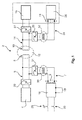
- Fig. 1 shows a system according to the invention for contactless energy and data transfer 2.
- a primary control unit 4 is used that modulates the data by way of alternating-voltage signals onto a carrier voltage at a carrier frequency and leads it as a first alternating-voltage signal by way of a primary line 6 to a primary coil 8.
- the primary coil 8 is arranged, for example, on a first vehicle part (not shown in this diagram), wherein this first vehicle part is preferably firmly fastened in a cabin or in some other location of a vehicle.
- a second vehicle part which is movable relative to the first vehicle part, may accommodate a secondary coil 10 which by approximate positioning or alignment with the primary coil 8 forms a transducer/transformer 12.
- There the modulated-on alternating-voltage signals are separated, by means of a filter (not shown) integrated in the secondary control unit 16, from the carrier frequency and are reconverted to data streams.
- a command for activating or operating a device may be transferred by sending a signal from the primary control unit 4 to the secondary control unit 16.
- the command may be converted by releasing an operating voltage to the corresponding device.
- a system is primarily intended for devices that have relatively low safety criticality. For example, in the case of a malfunction in one of the two control units, the entire communication between the two control units may break down unless correspondingly redundant measures are provided. Accordingly, the use of such systems to control vital devices does not suggest itself per se.
- said second alternating-voltage signal may also be transferred, by way of the transducer/transformer 12 comprising the primary coil 8 and the secondary coil 10, to the second connecting line 14.
- the special feature consists of implementing the application of this second alternating-voltage signal in such a manner that exclusively passive electronic components are used. This may be achieved by the use of an alternating-voltage source that is present at an alternating-voltage input 19 of a switching device 18 and that may be connected by means of a switch 20.
- an alternating voltage of a comparatively low frequency of a first frequency range of, for example, 50 to 1000 Hz and preferably of 380 Hz to 800 Hz is applied by way of a signal output 9 and a feed-in line 7 to the first connecting line 6 so that apart from the first alternating-voltage signal with a significantly higher carrier frequency starting from the primary control unit 4 also a low-frequency second alternating-voltage signal is transferred in a superimposed manner to the second connecting line 14.
- the switching device 18 may also be operated by means of a pressure switch 28 which, for example if the pressure falls to below a defined cabin pressure in the cabin of a vehicle, also causes the switching device 18 to emit a first alternating-voltage signal to the primary line.
- a decoupling transmitter 30 is arranged which forwards an alternating-voltage signal essentially in an unchanged manner, except galvanically separated.
- a second filter 31 is imaginable that exclusively lets through alternating-voltage signals comprising a frequency from the second frequency range. In this manner it is possible to prevent the entry of high-frequency first alternating-voltage signals from the primary control unit 4 by way of the switching device 18 to a higher-level system.
- a second decoupling transmitter 32 may be arranged that also emits to the device 26 to be activated an alternating-voltage signal, essentially unchanged, which alternating-voltage signal is present.
- a third filter 29 may be arranged that blocks second alternating-voltage signals from a second frequency range, while letting the high-frequency first alternating-voltage signals from the primary control unit 4 pass through.
- a fourth filter 27 may be arranged on the secondary line 14, which further filter 27 exclusively lets high-frequency first alternating-voltage signals pass through to the secondary control unit 16, while the second alternating-voltage signals are blocked.
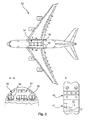
- Figure 2 shows an aircraft 33 with a cabin 34 in which several seats 36 are arranged on a cabin floor 38.
- PSUs 40 which comprise loudspeakers, switches, air nozzles and the like, are arranged above the seats 38.
- oxygen mask containers 41 with cover flaps 42 are integrated in the PSUs 40 or adjacent to them. The latter may be opened by means of a corresponding signal with the use of a corresponding release mechanism 43 so that oxygen masks (not shown) are deployed that are supplied with oxygen by means of an oxygen system.
- the system according to the invention according to Fig. 1 may be used, whose activation connection 11 is connected to the release mechanism 43.
Landscapes
- Engineering & Computer Science (AREA)
- Computer Networks & Wireless Communication (AREA)
- Signal Processing (AREA)
- Power Engineering (AREA)
- Mechanical Engineering (AREA)
- Electric Propulsion And Braking For Vehicles (AREA)
- Near-Field Transmission Systems (AREA)
- Lock And Its Accessories (AREA)
- Control Of Position, Course, Altitude, Or Attitude Of Moving Bodies (AREA)
Abstract
Description
- This application claims the benefit of the filing date of German Patent Application No.
10 2012 008 540.0 filed April 27, 2012 , the disclosure of which application is hereby incorporated herein by reference. - The invention relates to a system for the contactless transfer of energy and data and to a vehicle with such a system.
- In the state of the art, systems for the transfer of energy and data are known. In vehicles such systems may be used for providing energy or data for an on-board entertainment system, for illuminating devices or the like. Contactless transfer between a first vehicle part and a second vehicle part that is movable relative to the aforesaid makes it possible, for example, to electrically effortlessly connect rapidly reconfigurable passenger cabins of a vehicle with variably-positionable seats or devices arranged above seats to higher-level systems of the vehicle.
- In larger vehicles, for example in commercial aircraft, the safety of the design of technical devices is prescribed in several levels, depending on the intended criticality of the application of the devices under consideration. Apart from applications that are critical to the survival of passengers and to the integrity of the vehicle, furthermore, less critical or non-critical applications are imaginable. These gradations are often referred to as "design assurance levels (DALs)", wherein DAL level "A" is used for particularly critical applications, and DAL level "E" for particularly non-critical applications. The supply of electrical current and data to devices of DAL level A thus needs to be considerably more reliable or considerably safer than the supply to devices for applications of DAL level E. Cabling of release mechanisms of compartments for oxygen masks in cabins of commercial aircraft is predominantly carried out to DAL level B.
-
DE 10 2008 024 217 A1 discloses a system for contactless energy and data transfer, in which system a transducer/transformer is formed between the first vehicle part and the second vehicle part. Apart from the transfer of energy, data is transferred as alternating-voltage signals that are modulated onto a carrier signal with a carrier frequency. - The electrical connection of devices with stringent safety requirements, for example of release mechanisms of compartments for oxygen masks, on board commercial aircraft is usually implemented by separate cabling arrangements in order to achieve a high DAL level. In contrast to the aforesaid, devices in a passenger service unit (PSU), which devices are located above seats whose positions are variable, may be electrically connected, by means of a system for contactless energy and data transfer, to a higher-level system of the commercial aircraft. Since in a PSU the loudspeakers, lights or operating buttons have only relatively low application criticality, the contactless data and energy transfer system used for this may have a relatively low DAL level. However, this excludes the connection of critical devices, for example the release mechanisms for mask compartments, to such a system. However, adapting conventional cabling arrangements after reconfiguration of the cabin would result in additional cabling effort and expenditure.
- Accordingly, it may be considered an object of the invention to propose a system for transferring a signal, for example between a first vehicle part and a second vehicle part, which is movable relative to the first vehicle part, in which system there is no need to provide a wire-bound coupling, while nevertheless a higher DAL level may be achieved than is implementable by means of a known system for contactless energy and data transfer.
- The object is met by a system for the contactless transfer of energy and data with the features of the independent claim 1. Advantageous improvements are stated in the following description and in the subordinate claims.
- A system for the contactless transfer of energy and data comprises a transfer path with a primary coil, connected by way of a primary line to a primary control unit, and a secondary coil, connected by way of a secondary line to a secondary control unit, wherein the primary control unit is designed to lead data-modulated first alternating-voltage signals of a first frequency range into the primary coil, and the secondary control unit is designed to receive alternating-voltage signals of the first frequency range from the secondary coil, and to demodulate the modulated-on data. The system according to the invention further comprises a feed-in line connected to the primary line, an activation line connected to the secondary line, and a first filter arranged between the activation line and an activation connection, which first filter is permeable to second alternating-voltage signals of a second frequency range while blocking the first alternating-voltage signals of the first frequency range.
- Within the scope of the invention, a system for contactless energy and data transfer, which system is for example known from
DE 10 2008 024 217 A1 - In this context it is mentioned that the primary coil is preferably arranged in a vehicle-fixed or structure-fixed manner, i.e. in a fixed position within the vehicle, on a first vehicle part, thus forming a primary strand with the first connecting line and with the primary control unit, which primary strand is, for example, connected to a higher-level vehicle system. The first vehicle part may thus be a vehicle-fixed or structure-fixed component. It goes without saying that in order to improve the electromagnetic characteristics the primary coil is arranged in a primary core that comprises any form suitable for forming a transducer/transformer with a secondary coil. The primary coil or the primary core should be positioned in such a manner that alignment of a secondary coil results in the formation of a transdurcer/transformer.
- The secondary coil may, furthermore, be arranged in a movable second vehicle part. Movability relates to the suitability of assuming various positions within the vehicle if required. This may apply in the context of reconfiguration of the passenger cabin, in which the seat pitch of passenger seats is changed in order to vary, even temporarily, the number of seats in various classes. The second vehicle part may, for example, comprise a PSU in a vehicle cabin, or may be connected to said PSU, wherein in order to achieve reconfigurability of a passenger cabin the PSU may be arranged above movable passenger seats, aligned with said passenger seats, at various positions on stowage compartment panels or cover panels. Accordingly, the devices contained therein are supplied with electrical power and data by way of the transfer path comprising the primary coil and the secondary coil, which power and data are tapped by way of the secondary line and the secondary control unit as a secondary strand. In this arrangement, too, it is understood that the secondary coil should be arranged in a secondary core in order to improve the magnetic characteristics.
- Furthermore, in the context of their use in a cabin of a commercial aircraft it is imaginable to distribute a number of spaced apart primary coils over the cabin, with which primary coils secondary coils may form a transducer/transformer. In this arrangement the spacing of the primary coils relative to each other may be constant or variable. With the design of the primary coils in an elongated shape, because of the improved coverage the number of necessary primary coils may be reduced, although nevertheless great flexibility of positioning of the second vehicle parts is ensured.
- The data received by the primary control unit is modulated onto an alternating-voltage signal with this carrier frequency so that transfer by way of the primary coil to the secondary coil may occur, in which location the data are demodulated and made available. The achievable data rates in the transfer of energy and data by way of the transfer path depend on the carrier frequency, i.e. on the frequency of the first alternating-voltage signal without modulated-on data, which frequency is in the first frequency range. In order to achieve acceptable data transfer rates on board vehicles, the use of a frequency of several 100 kHz or higher is recommended. Accordingly, the first frequency range may, for example, be in the range of 50 kHz to 10 MHz; however, depending on required data rates it may significantly exceed these boundaries.
- The second alternating-voltage signal of the second frequency range, which signal is applied only when required, may be superimposed in a completely transparent manner on the first alternating-voltage signal of the first frequency range if the first frequency range and the second frequency range differ significantly. Advantageously, the boundaries of the first frequency range and of the second frequency range differ by a factor of 10 to 10,000, wherein the first frequency range covers higher frequencies than the second frequency range. Depending on the required data rates of the system, lower or considerably higher factors are also imaginable. In this manner the second alternating-voltage signal may transfer by way of the same transfer path into the secondary coil and in that location may reliably and precisely be filtered out by the correspondingly dimensioned first filter, without this resulting in interference by the first alternating-voltage signal. By means of the first filter, which lets the second alternating-voltage signal pass through to an activation connection, reliable transfer, of the second alternating-voltage signal, by way of the activation connection, to the critical device may be achieved.
- The first filter may be designed as a low-pass filter that is, for example, implemented as a first-order high pass in the form of an RC element. In this arrangement the reciprocal value of the product of the capacitance of the capacitor and the size of the resistor would be proportional to an achievable limiting frequency of the low-pass filter.
- In summary, it is a core aspect of the invention that for the transfer of an additional signal for a safety-critical device an already existing transfer path of a system for the contactless transfer of energy and data is used, while the primary and secondary control units connected to the system are, however, totally disregarded in order to ensure improved safety and reliability. Only a primary line, which extends in the primary strand between the primary control unit and the primary coil, is subjected to the additional second alternating-voltage signal, which is to be transferred, from the second frequency range, which second alternating-voltage signal is transferred into the secondary coil and is fed to the corresponding device already prior to reaching a secondary control unit present in the secondary strand.
- An advantageous embodiment comprises a switching device with a signal output, which switching device is designed to controllably apply an alternating-voltage signal from the second frequency range to the signal output, wherein the signal output is connected to the feed-in line. In this manner it is possible to selectively, for example by activating a switch, a pushbutton or some other suitable device for carrying out or initiating a switching process, to feed a second alternating-voltage signal of the second frequency range into the feed-in line. The switching device may comprise a switching unit in the form of a mechanical or electronic relay. The switching device may resemble an oxygen-switching device of a commercial aircraft, or it may be an oxygen-switching device, which switching device according to the state of the art by way of a cable-bound connection makes it possible to activate or release oxygen masks from a mask container.
- In an advantageous embodiment the switching device is connected to a pressure sensor and is designed to lead the alternating-voltage signal of the second frequency range to the signal output if the pressure level falls below a predetermined air pressure. In particular for use in a commercial aircraft this provides an advantage in that, if the pressure falls below a tolerable absolute pressure in the cabin, a first alternating-voltage signal may automatically be transferred to release mechanisms in second vehicle parts, which release mechanisms may, for example, comprise mask containers designed for the automatic release or deployment of oxygen masks from corresponding mask containers.
- In an advantageous embodiment the activation connection is connected to at least one actuator that is designed to carry out a movement when a second alternating-voltage signal is present. This may, in particular, be used for unlocking cover flaps that are arranged on mask containers that contain oxygen masks. Particularly preferably such containers comprise a snap-lock mechanism in which a springloaded latch holds the container flap in a closed position by means of a positive locking connection. If the actuator is moved when the second alternating-voltage signal is released, the latch may be released, against the spring tension, from the positive locking connection so that the cover flap is released from its closed position either controlled by gravity or under the influence of a further spring force.
- In an advantageous embodiment of the invention the second frequency range may extend from 50 Hz to 1,000 Hz. This includes the most frequently used alternating-voltage frequencies that may be used for releasing, activating or operating electrical devices in a vehicle. While an alternating voltage commonly used in households may be approximately 50 Hz, in a commercial aircraft alternating voltages ranging between 380 and 800 Hz are often used. Furthermore, it makes sense to select an extent of the voltage, which extent is common in vehicles, from a range of 12 V to 300 V, for example 115 V. The second alternating-voltage signal may also be implemented in the form of a pulsed direct-voltage signal, wherein for this purpose at least one voltage impulse is introduced into the feed-in line. The extent of the voltage is to be selected in such a manner that the transferred impulses transfer sufficient energy for the devices to be operated.
- The extent of the voltage of the second alternating-voltage signal to be transferred depends on the type of the device to be controlled. In this arrangement, the strand commencing from the feed-in line up to the activation connection is to be regarded as a replacement of a cable.
- In a further advantageous embodiment a first decoupling transmitter is arranged in the feed-in line. The impedance of the primary line may thus be decoupled from the source of the second alternating-voltage signal, and in particular from the feed-in line, so that any interference in the primary line and in the system for contactless energy and data transfer per se does not affect the integrity of a device that generates the second alternating-voltage signal. In addition to this, the electrical characteristics of the feed-in line, of the activation line and of all the connected devices essentially need not be taken into account in the design of the transfer path.
- Likewise, in an advantageous embodiment a second decoupling transmitter is arranged in the activation line. The second alternating-voltage signal is supplied by way of the second decoupling transmitter to the device to be controlled.
- A further advantageous embodiment comprises a second filter in the feed-in line, which second filter corresponds to the first filter. In this manner it is possible to prevent first alternating-voltage signals transferred into the secondary line from reaching the activation line.
- In a further advantageous embodiment a third filter is arranged in the primary line, and a fourth filter is arranged in the secondary line, wherein the third and the fourth filters are permeable to alternating-voltage signals from the first frequency range, while blocking them from the second frequency range. This prevents the primary control unit and the secondary control unit from being subjected to second alternating-voltage signals that may result in a malfunction. In this design the third filter is arranged between the primary control unit and the connection of the feed-in line, while the fourth filter is arranged between the secondary control unit and the connection of the activation line. Since the third filter and the fourth filter are to be permeable to significantly higher frequencies than the first filter and the second filter, the aforesaid may, for example, be designed as a high pass.
- The invention furthermore relates to a vehicle comprising a system as described above for the contactless transfer of energy and data. In this arrangement the vehicle is preferably an aircraft. Preferably, the vehicle comprises at least one first vehicle part and at least one second vehicle part that is movable relative to the first vehicle part, wherein at least one primary coil is arranged on the at least one first vehicle part, and a secondary coil is arranged on the at least one second vehicle part.
- In a preferred embodiment the first vehicle part is a vehicle-fixed component. This may be a covering element in a cabin, a stiffening or reinforcement element, a mount, a floor element or some similar equipment component or structural component. It may make sense, for example, as a first vehicle part to use a ceiling panel, overhead bins, a lateral lining or adjacent fixed parts in a vehicle cabin, in order to subject movably arranged second vehicle parts at a very high safety level to the second alternating-voltage signal from the second frequency range as required.
- In a preferred embodiment the second vehicle part comprises a container for oxygen masks, which container comprises a release mechanism that is connected to the activation connection and that opens the container when it receives the second alternating-voltage signal. The container may comprise a cover element that is preferably designed as a hinged lid. The release mechanism of the container keeps the cover element in a closed position and is connected to the activation connection so that when the second alternating-voltage signal is transferred an actuator integrated in the container activates the release mechanism, thereby releasing or deploying the oxygen mask.
- In an equally preferred embodiment, the vehicle comprises a multitude of spaced-apart primary coils on one or several first vehicle parts, as well as a multitude of second vehicle parts, on which secondary coils are arranged that may be made to align in each case with at least one primary coil. The primary coils may be arranged in a grid-like manner in order to form transducers/transformers with secondary coils at various locations in the vehicle.
- Further features, advantages and application options of the present invention are disclosed in the following description of the exemplary embodiments and of the figures. All the described and/or illustrated features per se and in any combination form the subject of the invention, even irrespective of their composition in the individual claims or their interrelationships. Furthermore, identical or similar objects in the figures have the same reference characters.
-
Fig. 1 shows a diagrammatic view of a system according to the invention for contactless energy and data transfer. -
Fig. 2 shows an aircraft with a system for contactless energy and data transfer arranged therein, and with several devices electrically supplied by means of the aforesaid. -
Fig. 1 shows a system according to the invention for contactless energy anddata transfer 2. For the transfer of energy and data, as described in more detail inDE 10 2008 024 217 A1primary control unit 4 is used that modulates the data by way of alternating-voltage signals onto a carrier voltage at a carrier frequency and leads it as a first alternating-voltage signal by way of aprimary line 6 to aprimary coil 8. Theprimary coil 8 is arranged, for example, on a first vehicle part (not shown in this diagram), wherein this first vehicle part is preferably firmly fastened in a cabin or in some other location of a vehicle. - A second vehicle part, which is movable relative to the first vehicle part, may accommodate a
secondary coil 10 which by approximate positioning or alignment with theprimary coil 8 forms a transducer/transformer 12. This means that alternating voltages applied to theprimary coil 8 are induced into thesecondary coil 10, from where, by way of a second connectingline 14, they reach asecondary control unit 16. There the modulated-on alternating-voltage signals are separated, by means of a filter (not shown) integrated in thesecondary control unit 16, from the carrier frequency and are reconverted to data streams. - Accordingly, a command for activating or operating a device may be transferred by sending a signal from the
primary control unit 4 to thesecondary control unit 16. In thesecondary control unit 16 the command may be converted by releasing an operating voltage to the corresponding device. Because of the multiple conversion of data to alternating-voltage signals and back, which apart from the analog signal circuit may also comprise corresponding logic and implementation to a protocol-based transfer system, such a system is primarily intended for devices that have relatively low safety criticality. For example, in the case of a malfunction in one of the two control units, the entire communication between the two control units may break down unless correspondingly redundant measures are provided. Accordingly, the use of such systems to control vital devices does not suggest itself per se. - By applying an additional, second, alternating-voltage signal to the first connecting
line 6, said second alternating-voltage signal may also be transferred, by way of the transducer/transformer 12 comprising theprimary coil 8 and thesecondary coil 10, to the second connectingline 14. The special feature consists of implementing the application of this second alternating-voltage signal in such a manner that exclusively passive electronic components are used. This may be achieved by the use of an alternating-voltage source that is present at an alternating-voltage input 19 of aswitching device 18 and that may be connected by means of aswitch 20. - By operating the
switch 20 an alternating voltage of a comparatively low frequency of a first frequency range of, for example, 50 to 1000 Hz and preferably of 380 Hz to 800 Hz is applied by way of a signal output 9 and a feed-inline 7 to the first connectingline 6 so that apart from the first alternating-voltage signal with a significantly higher carrier frequency starting from theprimary control unit 4 also a low-frequency second alternating-voltage signal is transferred in a superimposed manner to the second connectingline 14. By means of a correspondingfirst filter 22, which is designed to let through alternating voltages of frequencies from the first frequency range, and which is connected to thesecondary line 14, it is possible to exclusively transfer this low-frequency second alternating-voltage signal to anactivation line 24 that by way of anactivation connection 11 controls thedevice 26 to be activated. The signal path from theswitch 20 to the activatingdevice 26 is thus completely passive. - In addition or as an alternative, the switching
device 18 may also be operated by means of apressure switch 28 which, for example if the pressure falls to below a defined cabin pressure in the cabin of a vehicle, also causes theswitching device 18 to emit a first alternating-voltage signal to the primary line. - In addition, damage to the system for contactless energy and data transfer or damage to a device connected thereto may be prevented in that, for example, between the switching
device 18 and the first connecting line 6 adecoupling transmitter 30 is arranged which forwards an alternating-voltage signal essentially in an unchanged manner, except galvanically separated. In addition, asecond filter 31 is imaginable that exclusively lets through alternating-voltage signals comprising a frequency from the second frequency range. In this manner it is possible to prevent the entry of high-frequency first alternating-voltage signals from theprimary control unit 4 by way of theswitching device 18 to a higher-level system. - Likewise, on the second connecting line 14 a
second decoupling transmitter 32 may be arranged that also emits to thedevice 26 to be activated an alternating-voltage signal, essentially unchanged, which alternating-voltage signal is present. - In the primary line 6 a
third filter 29 may be arranged that blocks second alternating-voltage signals from a second frequency range, while letting the high-frequency first alternating-voltage signals from theprimary control unit 4 pass through. Furthermore, afourth filter 27 may be arranged on thesecondary line 14, which further filter 27 exclusively lets high-frequency first alternating-voltage signals pass through to thesecondary control unit 16, while the second alternating-voltage signals are blocked. -
Figure 2 shows anaircraft 33 with acabin 34 in whichseveral seats 36 are arranged on acabin floor 38.PSUs 40, which comprise loudspeakers, switches, air nozzles and the like, are arranged above theseats 38. Furthermore, integrated in thePSUs 40 or adjacent to them there areoxygen mask containers 41 with cover flaps 42. The latter may be opened by means of a corresponding signal with the use of acorresponding release mechanism 43 so that oxygen masks (not shown) are deployed that are supplied with oxygen by means of an oxygen system. In order to transfer electrical energy to an actuator (not shown separately) contained in therelease mechanism 43, the system according to the invention according toFig. 1 may be used, whoseactivation connection 11 is connected to therelease mechanism 43. For this purpose it is not necessary to establish separate, wire-bound, connections; instead, the already existing contactless energy and data transfer system may be used that is used for other, non-vital, purposes. Because of the slidability ofPSUs 40 in the reconfigurability of thecabin 34 withslidable seats 36 it is also possible to slide theoxygen mask containers 41 with theseats 36 so that it is also not necessary to carry out adaptation work relating to the electrical control of thesecontainers 41. - In addition, it should be pointed out that "comprising" does not exclude other elements or steps, and "a" or "one" does not exclude a plural number. Furthermore, it should be pointed out that features or steps which have been described with reference to one of the above exemplary embodiments may also be used in combination with other features or steps of other exemplary embodiments described above. Reference characters in the claims are not to be interpreted as limitations.
Claims (14)
- A system for the contactless transfer of energy and data,
comprising a transfer path with at least one primary coil (8), connected by way of a primary line (6) to a primary control unit (4), and at least one secondary coil (10) connected by way of a secondary line (14) to a secondary control unit (16),
wherein the primary control unit (4) is designed to lead data-modulated first alternating-voltage signals of a first frequency range into the primary coil (8), and
wherein the secondary control unit (16) is designed to receive the first alternating-voltage signals of the first frequency range from the secondary coil (10), and to demodulate the modulated-on data;
characterized by a feed-in line (7) connected to the primary line (6), an activation line (24) connected to the secondary line (14), and a first filter (22) arranged between the activation line (9) and an activation connection (11),
wherein the first filter (22) is permeable to second alternating-voltage signals of a second frequency range while blocking the first alternating-voltage signals of the first frequency range. - The system of claim 1, further comprising a switching device with a signal output (9), which switching device is designed to controllably apply an alternating-voltage signal from the second frequency range to the signal output (9), wherein the signal output (9) is connected to the feed-in line (7).
- The system of claim 2, wherein the switching device (18) is connected to a pressure sensor (28) and is designed to lead the alternating-voltage signal of the second frequency range to the signal output (9) if the pressure level falls below a predetermined air pressure.
- The system of any one of the preceding claims,
wherein the activation connection (11) is connected to at least one actuator that is designed to carry out a movement when a second alternating-voltage signal is present. - The system of any one of the preceding claims, wherein the first filter (22) is a low-pass filter.
- The system of any one of the preceding claims, wherein the boundaries of the first frequency range differ by a factor of 10 to 10,000 from the boundaries of the second frequency range.
- The system of any one of the preceding claims, further comprising a decoupling transmitter (30) in the feed-in line (7).
- The system of any one of the preceding claims, further comprising a decoupling transmitter (32) in the activation line (24).
- The system of any one of the preceding claims, further comprising a second filter (31) in the feed-in line (7), which second filter (31) corresponds to the first filter (22).
- The system of any one of the preceding claims, further comprising a third filter (29) in the primary line (6) and a fourth filter (27) in the secondary line (14), wherein the third and the fourth filters (29, 27) let alternating-voltage signals from the first frequency range pass through while blocking them from the second frequency range.
- The system of claim 10,
wherein the third filter (29) and the fourth filter (27) are high pass filters. - A vehicle with a first vehicle part and at least one second vehicle part, which is movable relative to the first vehicle part, and a system of any one of claims 1 to 11, wherein the primary coil (8) is attached to a first vehicle part, and the secondary coil (10) is attached to a second vehicle part that is variably positionable relative to the first vehicle part.
- The vehicle of claim 12, wherein the first vehicle part is a vehicle-fixed component.
- The vehicle of claim 12 or 13, wherein the second vehicle part comprises a closeable container (41) for oxygen masks, which container (41) has a release mechanism (43) that is connected to the activation connection (11) and that opens the container (41) when it receives the second alternating-voltage signal.
Applications Claiming Priority (2)
| Application Number | Priority Date | Filing Date | Title |
|---|---|---|---|
| US201261639249P | 2012-04-27 | 2012-04-27 | |
| DE102012008540A DE102012008540A1 (en) | 2012-04-27 | 2012-04-27 | System for contactless transmission of energy and data and a vehicle with such a system |
Publications (3)
| Publication Number | Publication Date |
|---|---|
| EP2658072A2 true EP2658072A2 (en) | 2013-10-30 |
| EP2658072A3 EP2658072A3 (en) | 2016-10-12 |
| EP2658072B1 EP2658072B1 (en) | 2019-09-11 |
Family
ID=48325385
Family Applications (1)
| Application Number | Title | Priority Date | Filing Date |
|---|---|---|---|
| EP13165568.0A Active EP2658072B1 (en) | 2012-04-27 | 2013-04-26 | System for contactless transfer of energy and data and vehicle with such a system |
Country Status (3)
| Country | Link |
|---|---|
| US (1) | US9319108B2 (en) |
| EP (1) | EP2658072B1 (en) |
| DE (1) | DE102012008540A1 (en) |
Cited By (1)
| Publication number | Priority date | Publication date | Assignee | Title |
|---|---|---|---|---|
| PL428297A1 (en) * | 2018-12-20 | 2019-07-29 | Politechnika Lubelska | System for contactless energy transfer between electric vehicles |
Families Citing this family (6)
| Publication number | Priority date | Publication date | Assignee | Title |
|---|---|---|---|---|
| CN105393465A (en) * | 2013-07-26 | 2016-03-09 | 皇家飞利浦有限公司 | Picking-up signals in electrically contactless manners |
| EP2842866A1 (en) * | 2013-08-30 | 2015-03-04 | Airbus Operations GmbH | Floor system for a vehicle and vehicle having a cabin and a floor made by such a floor system |
| JP2015076993A (en) * | 2013-10-09 | 2015-04-20 | ソニー株式会社 | Power feeding device, power receiving device, and power feeding system |
| US10562631B2 (en) * | 2016-09-30 | 2020-02-18 | The Boeing Company | Systems and methods for wirelessly transmitting electrical signals to an overhead stowage bin assembly of a vehicle |
| DE202017103847U1 (en) | 2017-06-28 | 2017-07-21 | Airbus Operations Gmbh | System for guiding a robot through a passenger aircraft cabin |
| DE102021104928A1 (en) | 2021-03-02 | 2022-09-08 | Airbus Operations Gmbh | Passenger service unit for a passenger cabin of an aircraft or spacecraft |
Citations (1)
| Publication number | Priority date | Publication date | Assignee | Title |
|---|---|---|---|---|
| DE102008024217A1 (en) | 2008-05-19 | 2009-12-03 | Airbus Deutschland Gmbh | System for contactless data and energy transmission |
Family Cites Families (13)
| Publication number | Priority date | Publication date | Assignee | Title |
|---|---|---|---|---|
| DE3413242A1 (en) * | 1984-04-07 | 1985-10-17 | Richard Hirschmann Radiotechnisches Werk, 7300 Esslingen | Frequency divider |
| US5559377A (en) * | 1989-04-28 | 1996-09-24 | Abraham; Charles | Transformer coupler for communication over various lines |
| US5455466A (en) * | 1993-07-29 | 1995-10-03 | Dell Usa, L.P. | Inductive coupling system for power and data transfer |
| US5856710A (en) * | 1997-08-29 | 1999-01-05 | General Motors Corporation | Inductively coupled energy and communication apparatus |
| DE10240080A1 (en) * | 2002-08-30 | 2004-03-11 | Siemens Ag | Method for wireless and contactless energy and data transport and associated device |
| US7248165B2 (en) * | 2003-09-09 | 2007-07-24 | Motorola, Inc. | Method and apparatus for multiple frequency RFID tag architecture |
| NZ540927A (en) * | 2005-06-22 | 2008-03-28 | Traffic Electronics Ltd | Communication system for inductive power transfer system |
| US7839011B2 (en) * | 2007-02-09 | 2010-11-23 | Siemens Medical Solutions Usa, Inc. | Method and apparatus for signal transmission with isolation in medical devices |
| US8975752B2 (en) * | 2008-01-09 | 2015-03-10 | Oracle America, Inc. | Multiple access over proximity communication |
| DE102009019994B4 (en) * | 2008-05-19 | 2020-08-13 | Airbus Operations Gmbh | Airplane with hybrid transmitters for contactless energy and data transmission |
| DE102008028258A1 (en) | 2008-06-13 | 2009-12-17 | Airbus Deutschland Gmbh | Autonomous O2 channel |
| EP2168635B1 (en) * | 2008-09-26 | 2017-06-28 | Zodiac Aerotechnics | Oxygen breathing device with redundant signal transmission |
| DE102009009189B4 (en) * | 2009-02-16 | 2011-06-16 | Airbus Operations Gmbh | Sensor and sensor network for an aircraft |
-
2012
- 2012-04-27 DE DE102012008540A patent/DE102012008540A1/en not_active Withdrawn
-
2013
- 2013-04-26 US US13/871,134 patent/US9319108B2/en active Active
- 2013-04-26 EP EP13165568.0A patent/EP2658072B1/en active Active
Patent Citations (1)
| Publication number | Priority date | Publication date | Assignee | Title |
|---|---|---|---|---|
| DE102008024217A1 (en) | 2008-05-19 | 2009-12-03 | Airbus Deutschland Gmbh | System for contactless data and energy transmission |
Cited By (1)
| Publication number | Priority date | Publication date | Assignee | Title |
|---|---|---|---|---|
| PL428297A1 (en) * | 2018-12-20 | 2019-07-29 | Politechnika Lubelska | System for contactless energy transfer between electric vehicles |
Also Published As
| Publication number | Publication date |
|---|---|
| EP2658072A3 (en) | 2016-10-12 |
| US9319108B2 (en) | 2016-04-19 |
| US20130285442A1 (en) | 2013-10-31 |
| DE102012008540A1 (en) | 2013-10-31 |
| EP2658072B1 (en) | 2019-09-11 |
Similar Documents
| Publication | Publication Date | Title |
|---|---|---|
| US9319108B2 (en) | System for contactless transfer of energy and data and vehicle with such a system | |
| US20090295223A1 (en) | System for contact less data and power transmission | |
| US8175762B2 (en) | Electrically activated aircraft landing gear control system and method | |
| US8245969B2 (en) | Plug-n-play power system for an accessory in an aircraft | |
| US9014840B2 (en) | Integrated cargo loading system architecture | |
| CN110329496A (en) | Aircraft electrical braking system | |
| US20080078871A1 (en) | System and method for electronically latching compartments | |
| EP1984243B1 (en) | Double-walled floor segment for a means of locomotion for accommodating system components | |
| US20140265481A1 (en) | Seat device for an aircraft or spacecraft | |
| US20070057121A1 (en) | Simplified power system for a cabin services system for an aircraft | |
| WO2015172857A1 (en) | Power and data distribution module and method for power and data distribution in an airborne vehicle | |
| CN104898465B (en) | Control module for a service system of a vehicle | |
| US8925867B2 (en) | Modular adaptive electrical freight loading system | |
| WO2014187869A1 (en) | In-vehicle entertainment system | |
| US8325232B2 (en) | Wireless camera surveillance system for an aircraft | |
| US10507740B2 (en) | Control device for the comfort equipment of a passenger transport vehicle seat module, seat module and system for controlling comfort equipment | |
| EP3241748B1 (en) | Seat module with wireless communication module, vehicle seat with seat module, aircraft and method for operating a seat module | |
| FR2817535B1 (en) | SYSTEM FOR AUTOMATICALLY CONTROLLING HYPERSUSTENTATORY DEVICES OF AN AIRCRAFT DURING THE TAKE-OFF | |
| US9840330B2 (en) | Energy supply system for an electrical seat device in an aircraft or spacecraft | |
| CA2807268A1 (en) | System for contactless power transfer | |
| DE102014204926B4 (en) | Method for transmitting information from a passenger seat to a cabin system and corresponding passenger seat | |
| US20170371332A1 (en) | Method for replacing a signal controlling an actuator in a remote-controlled flying device with another signal | |
| US12486140B2 (en) | Safety brake trigger | |
| US10843805B2 (en) | Systems to prevent inadvertent in-flight deployment of inflatable aircraft emergency evacuation slides | |
| US7971221B2 (en) | Overhead video system for an aircraft |
Legal Events
| Date | Code | Title | Description |
|---|---|---|---|
| PUAI | Public reference made under article 153(3) epc to a published international application that has entered the european phase |
Free format text: ORIGINAL CODE: 0009012 |
|
| AK | Designated contracting states |
Kind code of ref document: A2 Designated state(s): AL AT BE BG CH CY CZ DE DK EE ES FI FR GB GR HR HU IE IS IT LI LT LU LV MC MK MT NL NO PL PT RO RS SE SI SK SM TR |
|
| AX | Request for extension of the european patent |
Extension state: BA ME |
|
| PUAL | Search report despatched |
Free format text: ORIGINAL CODE: 0009013 |
|
| AK | Designated contracting states |
Kind code of ref document: A3 Designated state(s): AL AT BE BG CH CY CZ DE DK EE ES FI FR GB GR HR HU IE IS IT LI LT LU LV MC MK MT NL NO PL PT RO RS SE SI SK SM TR |
|
| AX | Request for extension of the european patent |
Extension state: BA ME |
|
| RIC1 | Information provided on ipc code assigned before grant |
Ipc: H04B 5/00 20060101ALN20160906BHEP Ipc: H02J 5/00 20160101AFI20160906BHEP Ipc: B60R 16/023 20060101ALN20160906BHEP Ipc: B60R 16/027 20060101ALN20160906BHEP Ipc: H02J 17/00 00000000ALI20160906BHEP Ipc: B64D 11/06 20060101ALN20160906BHEP Ipc: B64D 11/00 20060101ALN20160906BHEP |
|
| STAA | Information on the status of an ep patent application or granted ep patent |
Free format text: STATUS: REQUEST FOR EXAMINATION WAS MADE |
|
| 17P | Request for examination filed |
Effective date: 20170411 |
|
| RBV | Designated contracting states (corrected) |
Designated state(s): AL AT BE BG CH CY CZ DE DK EE ES FI FR GB GR HR HU IE IS IT LI LT LU LV MC MK MT NL NO PL PT RO RS SE SI SK SM TR |
|
| STAA | Information on the status of an ep patent application or granted ep patent |
Free format text: STATUS: EXAMINATION IS IN PROGRESS |
|
| 17Q | First examination report despatched |
Effective date: 20180423 |
|
| REG | Reference to a national code |
Ref country code: DE Ref legal event code: R079 Ref document number: 602013060271 Country of ref document: DE Free format text: PREVIOUS MAIN CLASS: H02J0005000000 Ipc: H02J0050800000 |
|
| GRAP | Despatch of communication of intention to grant a patent |
Free format text: ORIGINAL CODE: EPIDOSNIGR1 |
|
| STAA | Information on the status of an ep patent application or granted ep patent |
Free format text: STATUS: GRANT OF PATENT IS INTENDED |
|
| RIC1 | Information provided on ipc code assigned before grant |
Ipc: H02J 50/10 20160101ALI20190325BHEP Ipc: H04B 5/00 20060101ALN20190325BHEP Ipc: B64D 11/00 20060101ALN20190325BHEP Ipc: H02J 50/80 20160101AFI20190325BHEP Ipc: B64D 11/06 20060101ALN20190325BHEP Ipc: B60R 16/027 20060101ALN20190325BHEP Ipc: B60R 16/023 20060101ALN20190325BHEP |
|
| INTG | Intention to grant announced |
Effective date: 20190408 |
|
| GRAS | Grant fee paid |
Free format text: ORIGINAL CODE: EPIDOSNIGR3 |
|
| GRAA | (expected) grant |
Free format text: ORIGINAL CODE: 0009210 |
|
| STAA | Information on the status of an ep patent application or granted ep patent |
Free format text: STATUS: THE PATENT HAS BEEN GRANTED |
|
| AK | Designated contracting states |
Kind code of ref document: B1 Designated state(s): AL AT BE BG CH CY CZ DE DK EE ES FI FR GB GR HR HU IE IS IT LI LT LU LV MC MK MT NL NO PL PT RO RS SE SI SK SM TR |
|
| REG | Reference to a national code |
Ref country code: GB Ref legal event code: FG4D |
|
| RIN1 | Information on inventor provided before grant (corrected) |
Inventor name: BAUER, HANS-ACHIM Inventor name: ZYBALA, ANDRE |
|
| REG | Reference to a national code |
Ref country code: CH Ref legal event code: EP |
|
| REG | Reference to a national code |
Ref country code: AT Ref legal event code: REF Ref document number: 1179759 Country of ref document: AT Kind code of ref document: T Effective date: 20190915 |
|
| REG | Reference to a national code |
Ref country code: DE Ref legal event code: R096 Ref document number: 602013060271 Country of ref document: DE |
|
| REG | Reference to a national code |
Ref country code: IE Ref legal event code: FG4D |
|
| REG | Reference to a national code |
Ref country code: NL Ref legal event code: MP Effective date: 20190911 |
|
| REG | Reference to a national code |
Ref country code: LT Ref legal event code: MG4D |
|
| PG25 | Lapsed in a contracting state [announced via postgrant information from national office to epo] |
Ref country code: FI Free format text: LAPSE BECAUSE OF FAILURE TO SUBMIT A TRANSLATION OF THE DESCRIPTION OR TO PAY THE FEE WITHIN THE PRESCRIBED TIME-LIMIT Effective date: 20190911 Ref country code: HR Free format text: LAPSE BECAUSE OF FAILURE TO SUBMIT A TRANSLATION OF THE DESCRIPTION OR TO PAY THE FEE WITHIN THE PRESCRIBED TIME-LIMIT Effective date: 20190911 Ref country code: SE Free format text: LAPSE BECAUSE OF FAILURE TO SUBMIT A TRANSLATION OF THE DESCRIPTION OR TO PAY THE FEE WITHIN THE PRESCRIBED TIME-LIMIT Effective date: 20190911 Ref country code: LT Free format text: LAPSE BECAUSE OF FAILURE TO SUBMIT A TRANSLATION OF THE DESCRIPTION OR TO PAY THE FEE WITHIN THE PRESCRIBED TIME-LIMIT Effective date: 20190911 Ref country code: BG Free format text: LAPSE BECAUSE OF FAILURE TO SUBMIT A TRANSLATION OF THE DESCRIPTION OR TO PAY THE FEE WITHIN THE PRESCRIBED TIME-LIMIT Effective date: 20191211 Ref country code: NO Free format text: LAPSE BECAUSE OF FAILURE TO SUBMIT A TRANSLATION OF THE DESCRIPTION OR TO PAY THE FEE WITHIN THE PRESCRIBED TIME-LIMIT Effective date: 20191211 |
|
| PG25 | Lapsed in a contracting state [announced via postgrant information from national office to epo] |
Ref country code: ES Free format text: LAPSE BECAUSE OF FAILURE TO SUBMIT A TRANSLATION OF THE DESCRIPTION OR TO PAY THE FEE WITHIN THE PRESCRIBED TIME-LIMIT Effective date: 20190911 Ref country code: LV Free format text: LAPSE BECAUSE OF FAILURE TO SUBMIT A TRANSLATION OF THE DESCRIPTION OR TO PAY THE FEE WITHIN THE PRESCRIBED TIME-LIMIT Effective date: 20190911 Ref country code: AL Free format text: LAPSE BECAUSE OF FAILURE TO SUBMIT A TRANSLATION OF THE DESCRIPTION OR TO PAY THE FEE WITHIN THE PRESCRIBED TIME-LIMIT Effective date: 20190911 Ref country code: GR Free format text: LAPSE BECAUSE OF FAILURE TO SUBMIT A TRANSLATION OF THE DESCRIPTION OR TO PAY THE FEE WITHIN THE PRESCRIBED TIME-LIMIT Effective date: 20191212 Ref country code: RS Free format text: LAPSE BECAUSE OF FAILURE TO SUBMIT A TRANSLATION OF THE DESCRIPTION OR TO PAY THE FEE WITHIN THE PRESCRIBED TIME-LIMIT Effective date: 20190911 |
|
| REG | Reference to a national code |
Ref country code: AT Ref legal event code: MK05 Ref document number: 1179759 Country of ref document: AT Kind code of ref document: T Effective date: 20190911 |
|
| PG25 | Lapsed in a contracting state [announced via postgrant information from national office to epo] |
Ref country code: IT Free format text: LAPSE BECAUSE OF FAILURE TO SUBMIT A TRANSLATION OF THE DESCRIPTION OR TO PAY THE FEE WITHIN THE PRESCRIBED TIME-LIMIT Effective date: 20190911 Ref country code: EE Free format text: LAPSE BECAUSE OF FAILURE TO SUBMIT A TRANSLATION OF THE DESCRIPTION OR TO PAY THE FEE WITHIN THE PRESCRIBED TIME-LIMIT Effective date: 20190911 Ref country code: PT Free format text: LAPSE BECAUSE OF FAILURE TO SUBMIT A TRANSLATION OF THE DESCRIPTION OR TO PAY THE FEE WITHIN THE PRESCRIBED TIME-LIMIT Effective date: 20200113 Ref country code: NL Free format text: LAPSE BECAUSE OF FAILURE TO SUBMIT A TRANSLATION OF THE DESCRIPTION OR TO PAY THE FEE WITHIN THE PRESCRIBED TIME-LIMIT Effective date: 20190911 Ref country code: RO Free format text: LAPSE BECAUSE OF FAILURE TO SUBMIT A TRANSLATION OF THE DESCRIPTION OR TO PAY THE FEE WITHIN THE PRESCRIBED TIME-LIMIT Effective date: 20190911 Ref country code: AT Free format text: LAPSE BECAUSE OF FAILURE TO SUBMIT A TRANSLATION OF THE DESCRIPTION OR TO PAY THE FEE WITHIN THE PRESCRIBED TIME-LIMIT Effective date: 20190911 Ref country code: PL Free format text: LAPSE BECAUSE OF FAILURE TO SUBMIT A TRANSLATION OF THE DESCRIPTION OR TO PAY THE FEE WITHIN THE PRESCRIBED TIME-LIMIT Effective date: 20190911 |
|
| PG25 | Lapsed in a contracting state [announced via postgrant information from national office to epo] |
Ref country code: CZ Free format text: LAPSE BECAUSE OF FAILURE TO SUBMIT A TRANSLATION OF THE DESCRIPTION OR TO PAY THE FEE WITHIN THE PRESCRIBED TIME-LIMIT Effective date: 20190911 Ref country code: IS Free format text: LAPSE BECAUSE OF FAILURE TO SUBMIT A TRANSLATION OF THE DESCRIPTION OR TO PAY THE FEE WITHIN THE PRESCRIBED TIME-LIMIT Effective date: 20200224 Ref country code: SK Free format text: LAPSE BECAUSE OF FAILURE TO SUBMIT A TRANSLATION OF THE DESCRIPTION OR TO PAY THE FEE WITHIN THE PRESCRIBED TIME-LIMIT Effective date: 20190911 Ref country code: SM Free format text: LAPSE BECAUSE OF FAILURE TO SUBMIT A TRANSLATION OF THE DESCRIPTION OR TO PAY THE FEE WITHIN THE PRESCRIBED TIME-LIMIT Effective date: 20190911 |
|
| REG | Reference to a national code |
Ref country code: DE Ref legal event code: R097 Ref document number: 602013060271 Country of ref document: DE |
|
| PLBE | No opposition filed within time limit |
Free format text: ORIGINAL CODE: 0009261 |
|
| STAA | Information on the status of an ep patent application or granted ep patent |
Free format text: STATUS: NO OPPOSITION FILED WITHIN TIME LIMIT |
|
| PG2D | Information on lapse in contracting state deleted |
Ref country code: IS |
|
| PG25 | Lapsed in a contracting state [announced via postgrant information from national office to epo] |
Ref country code: DK Free format text: LAPSE BECAUSE OF FAILURE TO SUBMIT A TRANSLATION OF THE DESCRIPTION OR TO PAY THE FEE WITHIN THE PRESCRIBED TIME-LIMIT Effective date: 20190911 Ref country code: IS Free format text: LAPSE BECAUSE OF FAILURE TO SUBMIT A TRANSLATION OF THE DESCRIPTION OR TO PAY THE FEE WITHIN THE PRESCRIBED TIME-LIMIT Effective date: 20200112 |
|
| 26N | No opposition filed |
Effective date: 20200615 |
|
| PG25 | Lapsed in a contracting state [announced via postgrant information from national office to epo] |
Ref country code: SI Free format text: LAPSE BECAUSE OF FAILURE TO SUBMIT A TRANSLATION OF THE DESCRIPTION OR TO PAY THE FEE WITHIN THE PRESCRIBED TIME-LIMIT Effective date: 20190911 |
|
| PGFP | Annual fee paid to national office [announced via postgrant information from national office to epo] |
Ref country code: GB Payment date: 20200427 Year of fee payment: 8 |
|
| PG25 | Lapsed in a contracting state [announced via postgrant information from national office to epo] |
Ref country code: MC Free format text: LAPSE BECAUSE OF FAILURE TO SUBMIT A TRANSLATION OF THE DESCRIPTION OR TO PAY THE FEE WITHIN THE PRESCRIBED TIME-LIMIT Effective date: 20190911 |
|
| REG | Reference to a national code |
Ref country code: CH Ref legal event code: PL |
|
| PG25 | Lapsed in a contracting state [announced via postgrant information from national office to epo] |
Ref country code: LI Free format text: LAPSE BECAUSE OF NON-PAYMENT OF DUE FEES Effective date: 20200430 Ref country code: CH Free format text: LAPSE BECAUSE OF NON-PAYMENT OF DUE FEES Effective date: 20200430 Ref country code: LU Free format text: LAPSE BECAUSE OF NON-PAYMENT OF DUE FEES Effective date: 20200426 |
|
| REG | Reference to a national code |
Ref country code: BE Ref legal event code: MM Effective date: 20200430 |
|
| PG25 | Lapsed in a contracting state [announced via postgrant information from national office to epo] |
Ref country code: BE Free format text: LAPSE BECAUSE OF NON-PAYMENT OF DUE FEES Effective date: 20200430 |
|
| PG25 | Lapsed in a contracting state [announced via postgrant information from national office to epo] |
Ref country code: IE Free format text: LAPSE BECAUSE OF NON-PAYMENT OF DUE FEES Effective date: 20200426 |
|
| GBPC | Gb: european patent ceased through non-payment of renewal fee |
Effective date: 20210426 |
|
| PG25 | Lapsed in a contracting state [announced via postgrant information from national office to epo] |
Ref country code: GB Free format text: LAPSE BECAUSE OF NON-PAYMENT OF DUE FEES Effective date: 20210426 |
|
| PG25 | Lapsed in a contracting state [announced via postgrant information from national office to epo] |
Ref country code: TR Free format text: LAPSE BECAUSE OF FAILURE TO SUBMIT A TRANSLATION OF THE DESCRIPTION OR TO PAY THE FEE WITHIN THE PRESCRIBED TIME-LIMIT Effective date: 20190911 Ref country code: MT Free format text: LAPSE BECAUSE OF FAILURE TO SUBMIT A TRANSLATION OF THE DESCRIPTION OR TO PAY THE FEE WITHIN THE PRESCRIBED TIME-LIMIT Effective date: 20190911 Ref country code: CY Free format text: LAPSE BECAUSE OF FAILURE TO SUBMIT A TRANSLATION OF THE DESCRIPTION OR TO PAY THE FEE WITHIN THE PRESCRIBED TIME-LIMIT Effective date: 20190911 |
|
| PG25 | Lapsed in a contracting state [announced via postgrant information from national office to epo] |
Ref country code: MK Free format text: LAPSE BECAUSE OF FAILURE TO SUBMIT A TRANSLATION OF THE DESCRIPTION OR TO PAY THE FEE WITHIN THE PRESCRIBED TIME-LIMIT Effective date: 20190911 |
|
| PGFP | Annual fee paid to national office [announced via postgrant information from national office to epo] |
Ref country code: FR Payment date: 20240425 Year of fee payment: 12 |
|
| PGFP | Annual fee paid to national office [announced via postgrant information from national office to epo] |
Ref country code: DE Payment date: 20250422 Year of fee payment: 13 |
|
| PG25 | Lapsed in a contracting state [announced via postgrant information from national office to epo] |
Ref country code: FR Free format text: LAPSE BECAUSE OF NON-PAYMENT OF DUE FEES Effective date: 20250430 |