EP2658022A2 - Warming feature for aircraft fuel cells - Google Patents
Warming feature for aircraft fuel cells Download PDFInfo
- Publication number
- EP2658022A2 EP2658022A2 EP13165645.6A EP13165645A EP2658022A2 EP 2658022 A2 EP2658022 A2 EP 2658022A2 EP 13165645 A EP13165645 A EP 13165645A EP 2658022 A2 EP2658022 A2 EP 2658022A2
- Authority
- EP
- European Patent Office
- Prior art keywords
- fuel cell
- temperature
- aircraft
- fluid
- operating
- Prior art date
- Legal status (The legal status is an assumption and is not a legal conclusion. Google has not performed a legal analysis and makes no representation as to the accuracy of the status listed.)
- Granted
Links
- 239000000446 fuel Substances 0.000 title claims abstract description 154
- 238000010792 warming Methods 0.000 title claims abstract description 19
- 238000000034 method Methods 0.000 claims abstract description 17
- 230000004044 response Effects 0.000 claims abstract description 3
- 239000012530 fluid Substances 0.000 claims description 39
- 238000010438 heat treatment Methods 0.000 claims description 22
- 238000001816 cooling Methods 0.000 claims description 10
- 238000004891 communication Methods 0.000 claims description 5
- 239000002826 coolant Substances 0.000 claims description 5
- 230000001105 regulatory effect Effects 0.000 claims 4
- 238000003487 electrochemical reaction Methods 0.000 claims 1
- XLYOFNOQVPJJNP-UHFFFAOYSA-N water Substances O XLYOFNOQVPJJNP-UHFFFAOYSA-N 0.000 description 12
- 239000012528 membrane Substances 0.000 description 10
- 238000007710 freezing Methods 0.000 description 6
- 239000003792 electrolyte Substances 0.000 description 5
- 238000005516 engineering process Methods 0.000 description 4
- 230000008014 freezing Effects 0.000 description 4
- 239000001257 hydrogen Substances 0.000 description 4
- 229910052739 hydrogen Inorganic materials 0.000 description 4
- 238000009413 insulation Methods 0.000 description 4
- QVGXLLKOCUKJST-UHFFFAOYSA-N atomic oxygen Chemical compound [O] QVGXLLKOCUKJST-UHFFFAOYSA-N 0.000 description 3
- 239000001301 oxygen Substances 0.000 description 3
- 229910052760 oxygen Inorganic materials 0.000 description 3
- 238000010248 power generation Methods 0.000 description 3
- UFHFLCQGNIYNRP-UHFFFAOYSA-N Hydrogen Chemical compound [H][H] UFHFLCQGNIYNRP-UHFFFAOYSA-N 0.000 description 2
- 230000004913 activation Effects 0.000 description 2
- 230000002528 anti-freeze Effects 0.000 description 2
- 239000003054 catalyst Substances 0.000 description 2
- 239000012809 cooling fluid Substances 0.000 description 2
- 150000002500 ions Chemical class 0.000 description 2
- 239000007788 liquid Substances 0.000 description 2
- 239000005518 polymer electrolyte Substances 0.000 description 2
- 230000008569 process Effects 0.000 description 2
- 239000007787 solid Substances 0.000 description 2
- 239000013589 supplement Substances 0.000 description 2
- 230000004075 alteration Effects 0.000 description 1
- 239000006227 byproduct Substances 0.000 description 1
- 238000006243 chemical reaction Methods 0.000 description 1
- 230000003247 decreasing effect Effects 0.000 description 1
- 230000000593 degrading effect Effects 0.000 description 1
- 230000018044 dehydration Effects 0.000 description 1
- 238000006297 dehydration reaction Methods 0.000 description 1
- 230000003111 delayed effect Effects 0.000 description 1
- 230000000694 effects Effects 0.000 description 1
- 230000007613 environmental effect Effects 0.000 description 1
- 239000007789 gas Substances 0.000 description 1
- 150000002431 hydrogen Chemical class 0.000 description 1
- -1 hydrogen ions Chemical class 0.000 description 1
- GPRLSGONYQIRFK-UHFFFAOYSA-N hydron Chemical compound [H+] GPRLSGONYQIRFK-UHFFFAOYSA-N 0.000 description 1
- 230000007774 longterm Effects 0.000 description 1
- 238000012544 monitoring process Methods 0.000 description 1
- 239000007800 oxidant agent Substances 0.000 description 1
- 230000001590 oxidative effect Effects 0.000 description 1
- 238000006467 substitution reaction Methods 0.000 description 1
- 230000000153 supplemental effect Effects 0.000 description 1
- 238000010257 thawing Methods 0.000 description 1
- 238000011144 upstream manufacturing Methods 0.000 description 1
Images


Classifications
-
- H—ELECTRICITY
- H01—ELECTRIC ELEMENTS
- H01M—PROCESSES OR MEANS, e.g. BATTERIES, FOR THE DIRECT CONVERSION OF CHEMICAL ENERGY INTO ELECTRICAL ENERGY
- H01M8/00—Fuel cells; Manufacture thereof
- H01M8/04—Auxiliary arrangements, e.g. for control of pressure or for circulation of fluids
- H01M8/04223—Auxiliary arrangements, e.g. for control of pressure or for circulation of fluids during start-up or shut-down; Depolarisation or activation, e.g. purging; Means for short-circuiting defective fuel cells
- H01M8/04253—Means for solving freezing problems
-
- B—PERFORMING OPERATIONS; TRANSPORTING
- B64—AIRCRAFT; AVIATION; COSMONAUTICS
- B64D—EQUIPMENT FOR FITTING IN OR TO AIRCRAFT; FLIGHT SUITS; PARACHUTES; ARRANGEMENTS OR MOUNTING OF POWER PLANTS OR PROPULSION TRANSMISSIONS IN AIRCRAFT
- B64D41/00—Power installations for auxiliary purposes
-
- H—ELECTRICITY
- H01—ELECTRIC ELEMENTS
- H01M—PROCESSES OR MEANS, e.g. BATTERIES, FOR THE DIRECT CONVERSION OF CHEMICAL ENERGY INTO ELECTRICAL ENERGY
- H01M8/00—Fuel cells; Manufacture thereof
- H01M8/04—Auxiliary arrangements, e.g. for control of pressure or for circulation of fluids
- H01M8/04007—Auxiliary arrangements, e.g. for control of pressure or for circulation of fluids related to heat exchange
- H01M8/04014—Heat exchange using gaseous fluids; Heat exchange by combustion of reactants
-
- H—ELECTRICITY
- H01—ELECTRIC ELEMENTS
- H01M—PROCESSES OR MEANS, e.g. BATTERIES, FOR THE DIRECT CONVERSION OF CHEMICAL ENERGY INTO ELECTRICAL ENERGY
- H01M8/00—Fuel cells; Manufacture thereof
- H01M8/04—Auxiliary arrangements, e.g. for control of pressure or for circulation of fluids
- H01M8/04007—Auxiliary arrangements, e.g. for control of pressure or for circulation of fluids related to heat exchange
- H01M8/04029—Heat exchange using liquids
-
- H—ELECTRICITY
- H01—ELECTRIC ELEMENTS
- H01M—PROCESSES OR MEANS, e.g. BATTERIES, FOR THE DIRECT CONVERSION OF CHEMICAL ENERGY INTO ELECTRICAL ENERGY
- H01M8/00—Fuel cells; Manufacture thereof
- H01M8/04—Auxiliary arrangements, e.g. for control of pressure or for circulation of fluids
- H01M8/04007—Auxiliary arrangements, e.g. for control of pressure or for circulation of fluids related to heat exchange
- H01M8/04037—Electrical heating
-
- H—ELECTRICITY
- H01—ELECTRIC ELEMENTS
- H01M—PROCESSES OR MEANS, e.g. BATTERIES, FOR THE DIRECT CONVERSION OF CHEMICAL ENERGY INTO ELECTRICAL ENERGY
- H01M8/00—Fuel cells; Manufacture thereof
- H01M8/04—Auxiliary arrangements, e.g. for control of pressure or for circulation of fluids
- H01M8/04298—Processes for controlling fuel cells or fuel cell systems
- H01M8/04313—Processes for controlling fuel cells or fuel cell systems characterised by the detection or assessment of variables; characterised by the detection or assessment of failure or abnormal function
- H01M8/0432—Temperature; Ambient temperature
-
- H—ELECTRICITY
- H01—ELECTRIC ELEMENTS
- H01M—PROCESSES OR MEANS, e.g. BATTERIES, FOR THE DIRECT CONVERSION OF CHEMICAL ENERGY INTO ELECTRICAL ENERGY
- H01M8/00—Fuel cells; Manufacture thereof
- H01M8/04—Auxiliary arrangements, e.g. for control of pressure or for circulation of fluids
- H01M8/04298—Processes for controlling fuel cells or fuel cell systems
- H01M8/04694—Processes for controlling fuel cells or fuel cell systems characterised by variables to be controlled
- H01M8/04701—Temperature
- H01M8/04723—Temperature of the coolant
-
- H—ELECTRICITY
- H01—ELECTRIC ELEMENTS
- H01M—PROCESSES OR MEANS, e.g. BATTERIES, FOR THE DIRECT CONVERSION OF CHEMICAL ENERGY INTO ELECTRICAL ENERGY
- H01M8/00—Fuel cells; Manufacture thereof
- H01M8/04—Auxiliary arrangements, e.g. for control of pressure or for circulation of fluids
- H01M8/04298—Processes for controlling fuel cells or fuel cell systems
- H01M8/04694—Processes for controlling fuel cells or fuel cell systems characterised by variables to be controlled
- H01M8/04746—Pressure; Flow
- H01M8/04768—Pressure; Flow of the coolant
-
- B—PERFORMING OPERATIONS; TRANSPORTING
- B64—AIRCRAFT; AVIATION; COSMONAUTICS
- B64D—EQUIPMENT FOR FITTING IN OR TO AIRCRAFT; FLIGHT SUITS; PARACHUTES; ARRANGEMENTS OR MOUNTING OF POWER PLANTS OR PROPULSION TRANSMISSIONS IN AIRCRAFT
- B64D41/00—Power installations for auxiliary purposes
- B64D2041/005—Fuel cells
-
- B—PERFORMING OPERATIONS; TRANSPORTING
- B64—AIRCRAFT; AVIATION; COSMONAUTICS
- B64D—EQUIPMENT FOR FITTING IN OR TO AIRCRAFT; FLIGHT SUITS; PARACHUTES; ARRANGEMENTS OR MOUNTING OF POWER PLANTS OR PROPULSION TRANSMISSIONS IN AIRCRAFT
- B64D2221/00—Electric power distribution systems onboard aircraft
-
- H—ELECTRICITY
- H01—ELECTRIC ELEMENTS
- H01M—PROCESSES OR MEANS, e.g. BATTERIES, FOR THE DIRECT CONVERSION OF CHEMICAL ENERGY INTO ELECTRICAL ENERGY
- H01M8/00—Fuel cells; Manufacture thereof
- H01M8/10—Fuel cells with solid electrolytes
- H01M2008/1095—Fuel cells with polymeric electrolytes
-
- H—ELECTRICITY
- H01—ELECTRIC ELEMENTS
- H01M—PROCESSES OR MEANS, e.g. BATTERIES, FOR THE DIRECT CONVERSION OF CHEMICAL ENERGY INTO ELECTRICAL ENERGY
- H01M2250/00—Fuel cells for particular applications; Specific features of fuel cell system
- H01M2250/20—Fuel cells in motive systems, e.g. vehicle, ship, plane
-
- Y—GENERAL TAGGING OF NEW TECHNOLOGICAL DEVELOPMENTS; GENERAL TAGGING OF CROSS-SECTIONAL TECHNOLOGIES SPANNING OVER SEVERAL SECTIONS OF THE IPC; TECHNICAL SUBJECTS COVERED BY FORMER USPC CROSS-REFERENCE ART COLLECTIONS [XRACs] AND DIGESTS
- Y02—TECHNOLOGIES OR APPLICATIONS FOR MITIGATION OR ADAPTATION AGAINST CLIMATE CHANGE
- Y02E—REDUCTION OF GREENHOUSE GAS [GHG] EMISSIONS, RELATED TO ENERGY GENERATION, TRANSMISSION OR DISTRIBUTION
- Y02E60/00—Enabling technologies; Technologies with a potential or indirect contribution to GHG emissions mitigation
- Y02E60/30—Hydrogen technology
- Y02E60/50—Fuel cells
-
- Y—GENERAL TAGGING OF NEW TECHNOLOGICAL DEVELOPMENTS; GENERAL TAGGING OF CROSS-SECTIONAL TECHNOLOGIES SPANNING OVER SEVERAL SECTIONS OF THE IPC; TECHNICAL SUBJECTS COVERED BY FORMER USPC CROSS-REFERENCE ART COLLECTIONS [XRACs] AND DIGESTS
- Y02—TECHNOLOGIES OR APPLICATIONS FOR MITIGATION OR ADAPTATION AGAINST CLIMATE CHANGE
- Y02T—CLIMATE CHANGE MITIGATION TECHNOLOGIES RELATED TO TRANSPORTATION
- Y02T90/00—Enabling technologies or technologies with a potential or indirect contribution to GHG emissions mitigation
- Y02T90/40—Application of hydrogen technology to transportation, e.g. using fuel cells
Definitions
- This subject matter disclosed herein relates to a fuel cell system provided for use on board an aircraft and, in particular, to temperature regulation of such a fuel cell system.
- Fuel cells generate electrical energy with low emissions and a high level of efficiency.
- the power generated by an aircraft fuel cell may be utilized to supplement or replace the primary power generation system.
- An aircraft fuel call may also be utilized for emergency power generation to supplement or replace an aircraft ram air turbine.
- Thermal regulation is an important consideration for fuel cells utilized in aircraft emergency power generation systems. Due to the immediate demand for power in an emergency situation, delayed start times caused by a cold fuel cell are unacceptable. If a warming feature is not available for the fuel cell, a supplemental battery system will be necessary to provide power until the fuel cell has warmed to its operational temperature. The use of a battery system is both heavy and expensive.
- Conventional fuel cells include an anode region and a cathode region separated by an electrolyte.
- a fuel for example hydrogen
- an oxygen-containing oxidant such as air
- the electrolyte is a polymer electrolyte membrane (PEM)
- the hydrogen molecules react at an anode catalyst in the anode region to form positively charged hydrogen ions (H+) and transfer electrons to the electrode.
- the H+ ions which are formed in the anode region, then diffuse through the electrolyte to the cathode where they react, at a cathode catalyst, with the oxygen supplied to the cathode and the electrons that are transferred to the cathode by way of an external circuit, forming water.
- a system for warming a fuel cell on an aircraft, the system including at least one fuel cell.
- the fuel cell includes an anode and a cathode for creating thermal and electrical energy.
- a temperature sensor measures a first temperature of the fuel cell.
- a control unit is coupled to the temperature sensor. The control unit increases the first temperature to a second temperature in response to the first temperature being at least equal to a selected temperature threshold. Increasing of the first temperature is indicative of the control unit operating in a warming mode. The second temperature is higher than the selected temperature threshold.
- a method of operating a fuel cell on an aircraft wherein the fuel cell includes a membrane between an anode and a cathode and a sensor positioned to measure the temperature of the fuel cell.
- the method includes sensing the temperature of the fuel cell. If the temperature sensed is above a selected threshold, the fuel cell is operated in a first mode. If the temperature sensed is equal to or less than the selected threshold, the fuel cell is operated in a second mode.
- a polymer electrolyte membrane (PEM) fuel cell shows high performance at temperatures between about 60°C (333 Kelvin) and about 80°C (353 Kelvin). Performance of the fuel cell is reduced at lower temperatures because the reaction activation and ion conductance of the electrolyte membrane are decreased. Particularly, if the ambient temperature falls below 0°C (273 Kelvin) the temperature of the fuel cell stack may also fall below 0°C (273 Kelvin). This can cause the water used for electrode activation and hydrogen ion transfer in an electrolyte membrane to freeze, resulting in degraded performance. For this reason, when a fuel cell starts at a low temperature, it is very important to raise the temperature to 0°C (273 Kelvin) or greater in order to warm the inside of the fuel cell stack and melt any frozen water.
- PEM polymer electrolyte membrane
- Freezing of the water inside a fuel cell can occur often when the fuel cell is contained in a region of an aircraft that is not temperature controlled.
- the fuel cell will be considered in an "idle" state when not generating power.
- a fuel cell on an aircraft may be idle when the aircraft is in-flight, taxiing, long-term parking, or undergoing service. Atmospheric temperature variations resulting from flight or environmental conditions, such as take-off and landing, may cause freezing and thawing cycles to occur within an idle fuel cell, thereby degrading the performance and life of the fuel cell.
- the critical layer of the fuel cell which consists of the membrane and electrodes, may retain liquid water even below 0° C (273 Kelvin).
- the electrodes are able to retain water up to approximately -10°C (263 Kelvin) due to a lowered freezing point associated with capillary effects, and the membrane may have some "bound" water with a freezing point as low as -40°C (233 Kelvin).
- a low temperature for keeping the fuel cell warm to enable rapid startup and minimal loss of performance associated with freeze-thaw cycles is chosen to be approximately -10°C (263 Kelvin).
- the coldest warming temperature could be as low as -30°C (243 Kelvin).
- a thermal control subsystem 10 for a fuel cell system located on an aircraft is illustrated.
- a fuel cell stack 20 and the associated subsystems in direct or fluid communication with the fuel cell stack 20 are at an elevated temperature.
- the operating temperature of a proton exchange membrane (PEM) fuel cell is commonly in the range of between about 60°C (333 Kelvin) and about 85°C (358 Kelvin). Therefore, the various subsystems in direct or fluid communication with the fuel cell stack 20 are similarly at an elevated temperature when the fuel cell system becomes idle. When the fuel cell system is in an idle state, assuming a sub-freezing ambient temperature, the various subsystems will cool rapidly.
- PEM proton exchange membrane
- the fuel cell stack 20 After a sufficiently long period of time, the fuel cell stack 20 will eventually cool to the sub-freezing ambient temperature. Positioned adjacent to or within the fuel cell stack 20 is a temperature sensor 44 connected to a control device 50 for monitoring the temperature of the stack 20. When the temperature of the idle fuel cell stack 20 falls below a selected threshold, the control device 50 will shift the operation of the fuel cell system from an idle first mode to a second warming mode.
- An exemplary selected temperature threshold may be in the range of between about 4°C (277 Kelvin) and -10°C (263 Kelvin). More specifically, an exemplary selected temperature may be 0°C (273 Kelvin).
- the fuel cell stack may include a series of fuel cells stacked and held together by pressure plates. The temperature of the fuel cell stack 20 may vary from fuel cell to fuel cell.
- the temperature sensor 44 used to drive the control system may be arranged to measure the temperature of the coolest part of the fuel cell stack 20, such as at the fuel cells adjacent the pressure plates for example.
- a thermal control subsystem 10 increases the temperature of a fuel cell stack 20 using warm air from another aircraft subsystem.
- a warm air supply 30 is fluidly connected to an inlet 22 of the fuel cell stack 20 by a conduit 36.
- Exemplary sources that may act as air supply 30 include the airplane's air supply management system, cabin air, and engine bleed air.
- the temperature of the air provided by the air supply 30 may be up to about 95°C (368 Kelvin) depending on the source of the air.
- thermal energy is transferred from the air A to the fuel cell stack 20.
- the air A then exits through outlet 24 of the fuel cell stack 20 and is released in area 60, such as a within another section of the aircraft or to the atmosphere, for example.
- the air A may be returned to the air supply 30 from which it was taken by a conduit 38.
- a valve 42 Disposed along the fluid path between the outlet 34 of the air supply 30 and the inlet 22 of the fuel cell stack 20 is a valve 42 operable between an open and a closed position.
- a pump 40 is located along the conduit 38 for circulating the air from the fuel cell stack 20 back to the air supply 30.
- the pump 40 and the valve 42 are connected to a control device 50. Once a temperature sensor 44 determines that the temperature of the fuel cell stack 20 is below a selected threshold, the control device 50 will begin to operate in the second mode by opening the valve 42, so that air will flow from the air supply 30 to the fuel cell stack 20.
- the control device 50 may run the pump 40 to circulate the cool air exiting the fuel cell stack 20 back to the air supply 30.
- the warm air A is circulated around the outside of the fuel cell stack 20 rather than through it.
- a thermal control subsystem 110 warms a fuel cell stack 120 using one or more resistive electrical elements 160.
- the resistive electrical element 160 may be positioned adjacent the fuel cell stack 120 or alternately may be embedded within the end plates or pressure plates of the fuel cell stack 120.
- the resistive electrical element 160 is a heater.
- thermal insulation 180 such as an insulating jacket for example, surrounds the fuel cell stack 120. The thermal insulation will slow the cooling of the idle fuel cell stack 120 by retaining some of the heat generated during operation.
- the thermal insulation 180 illustrated may be used in conjunction with any of the thermal control subsystems disclosed herein.
- the control device 150 switches from a first mode to a second warming mode. In the second warming mode, the control device 150 sends a signal to activate the resistive electrical element 160.
- power is provided to the resistive electrical element 160 by a power source 170.
- the power source 170 is the electrical grid of the aircraft. In another embodiment, the power source 170 is a battery. In yet another embodiment, when the aircraft is parked, ground power may be used to power the resistive electrical element 160.
- an outlet 224 of a fuel cell stack 220 is fluidly connected to an inlet 232 of a heat exchanger 230 by a first conduit 226.
- a second conduit 236 connects the outlet 234 of the heat exchanger 230 with the inlet 222 of the fuel cell 220 to form a thermal management loop.
- a fluid C such as air or a coolant including water or antifreeze for example, circulates within the thermal management loop. If fluid C is antifreeze, thermal control subsystem 210 may not be applied to porous bipolar plate fuel cells.
- a control valve 242 is provided along conduit 226 between the outlet 224 of the fuel cell stack 220 and the inlet 232 of the heat exchanger 230.
- the valve 242 is operable between a first position and a second position to control the circulation of the fluid C within the thermal management loop.
- bypass conduit 227 connects conduit 226 to conduit 236 adjacent the heat exchanger 230 in order to redirect a flow of fluid.
- the end of bypass conduit 227 is connected to valve 242.
- valve 242 is a three way valve such that when the fuel cell 220 is idle, the flow of fluid C may be redirected through bypass conduit 227, rather than through the heat exchanger 230.
- the fluid C is circulated by a pump 240 under control of the control device 250.
- the fluid C has a temperature generally in the range of between -10°C (263 Kelvin) and the temperature of the fuel cell 220. If water is used as a coolant fluid, the fluid C temperature would be limited to 0°C (273 Kelvin).
- An accumulator 238 may be provided upstream from the pump 240.
- a heating device 239 such as a wire mesh heater for example, may be positioned within the accumulator 238 to increase the temperature of the fluid C being circulated to the fuel cell stack 220.
- the pump 240, the valve 242, and the heating device 239 are operably coupled to the control device 250.
- this thermal management loop uses fluid C to transfer heat to the fuel cell stack 220 from the heating device 239 when the fuel cell 220 is idling.
- this same thermal management loop 210 may serve as a cooling loop that transfers thermal energy from the fuel cell stack 220 to the environment via the heat exchanger 230.
- the control device 250 may be programmed to operate the heating device 239 within accumulator 238, causing the fluid C to become heated. Additionally, the control device 250 opens the valve 242 at the end of bypass conduit 227 and activates the pump 240 to circulate the fluid C through the fuel cell stack 220.
- Circulation of the fluid C will transfer thermal energy from the heating device 239 to the fuel cell stack 220.
- the cooled fluid C flows through bypass conduit 227 and into the accumulator 238 where the fluid C may be heated by the heating device 239.
- the bypass conduit 227 of thermal management system 210 includes a heat exchanger 229 rather than a heating device 239 while all other components remain substantially the same as the system shown and described with reference to FIG. 3 .
- the heat exchanger 229 is located in a temperature controlled area of the aircraft, such as in the cabin for example. As the fluid C circulates through the heat exchanger 229, heat from the surrounding air will transfer to the fluid C.
- the thermal control subsystem 210 illustrated in FIG. 5 is a variation of the thermal control subsystem of FIG. 4 for warming a fuel cell stack 220.
- the fuel cell in FIG. 5 includes a dedicated cooling loop 300 and a separate, dedicated heating loop 310.
- the outlet 224 of the fuel cell stack 220 is fluidly connected to an inlet 268 of a heat exchanger 270 by a first conduit 260.
- a second conduit 274 connects the outlet 272 of the heat exchanger 270 with the inlet 222 of the fuel cell stack 220 to form a heating loop.
- the heat exchanger 270 is located in a temperature controlled area in the aircraft, such as in the cabin for example.
- a warming fluid H such as water or air for example, circulates within the heating loop 310.
- a cooling fluid C such as water for example, circulates within the cooling loop 300.
- the heating loop 310 includes a control valve 262 and a pump 280 for circulating the fluid H.
- the cooling loop 300 includes a control valve 242 and a pump 240 for circulating the fluid C.
- control valve 242 of the cooling loop 300 will be open and the control valve 262 of the heating loop 310 will be closed. Opening of control valve 242 and operation of pump 240 will circulate the cooling fluid C and will remove heat from the fuel cell 220.
- the cooling loop 300 does not include a bypass conduit, or a heating device disposed within the accumulator 238.
- both control valves 242, 262 are closed such that neither the heating loop 310 nor the cooling loop 300 is operating.
- the control device 250 will initiate the operation of the heating loop 310 by opening control valve 262 and running pump 280 to circulate the fluid H through the fuel cell 220.
- the heating loop 310 may additionally include an accumulator 282.
- the fuel cell stack of any of the prior embodiments may be warmed by operating the fuel cell at a low or minimum load.
- the heat produced as a byproduct of the electrochemical process of the fuel cell warms the fuel cell stack to a temperature above the minimum threshold.
- a large supply source of both hydrogen and oxygen is required.
- the fuel cell when the fuel cell is idle, power is required to operate the associated devices, such as a control device, a pump, or a heating device for example. Because the fuel cell is not generating power when it is idle, the power for the associated devices is supplied by an alternate source.
- Exemplary power sources include a battery, the power grid of the aircraft, ground power if the aircraft is parked, and any other means known to a person skilled in the art.
- any of the embodiments of the invention discussed above may be applied to a fuel cell system of an aircraft individually or in combination with any of the other embodiments.
- the fuel cell when the fuel cell system operates in a second mode, the fuel cell may operate at a minimum load and include a resistive electrical heating element.
- the resistive electrical heating element When applied together to the fuel cell system, the resistive electrical heating element may be driven using the electrical power generated by the fuel cell stack.
- a thermal insulation such as an insulating jacket, may surround any of the fuel cell stacks in the previously described thermal control systems.
Landscapes
- Engineering & Computer Science (AREA)
- Chemical & Material Sciences (AREA)
- Life Sciences & Earth Sciences (AREA)
- Manufacturing & Machinery (AREA)
- Sustainable Development (AREA)
- Sustainable Energy (AREA)
- Chemical Kinetics & Catalysis (AREA)
- Electrochemistry (AREA)
- General Chemical & Material Sciences (AREA)
- Combustion & Propulsion (AREA)
- Aviation & Aerospace Engineering (AREA)
- Fuel Cell (AREA)
Abstract
Description
- This subject matter disclosed herein relates to a fuel cell system provided for use on board an aircraft and, in particular, to temperature regulation of such a fuel cell system.
- Fuel cells generate electrical energy with low emissions and a high level of efficiency. The power generated by an aircraft fuel cell may be utilized to supplement or replace the primary power generation system. An aircraft fuel call may also be utilized for emergency power generation to supplement or replace an aircraft ram air turbine.
- Thermal regulation is an important consideration for fuel cells utilized in aircraft emergency power generation systems. Due to the immediate demand for power in an emergency situation, delayed start times caused by a cold fuel cell are unacceptable. If a warming feature is not available for the fuel cell, a supplemental battery system will be necessary to provide power until the fuel cell has warmed to its operational temperature. The use of a battery system is both heavy and expensive.
- Conventional fuel cells include an anode region and a cathode region separated by an electrolyte. When the fuel cell is operated, a fuel, for example hydrogen, is supplied to the anode side and an oxygen-containing oxidant, such as air, is supplied to the cathode side. In fuel cells where the electrolyte is a polymer electrolyte membrane (PEM), the hydrogen molecules react at an anode catalyst in the anode region to form positively charged hydrogen ions (H+) and transfer electrons to the electrode. The H+ ions, which are formed in the anode region, then diffuse through the electrolyte to the cathode where they react, at a cathode catalyst, with the oxygen supplied to the cathode and the electrons that are transferred to the cathode by way of an external circuit, forming water.
- According to an embodiment of the invention, a system is provided for warming a fuel cell on an aircraft, the system including at least one fuel cell. The fuel cell includes an anode and a cathode for creating thermal and electrical energy. A temperature sensor measures a first temperature of the fuel cell. A control unit is coupled to the temperature sensor. The control unit increases the first temperature to a second temperature in response to the first temperature being at least equal to a selected temperature threshold. Increasing of the first temperature is indicative of the control unit operating in a warming mode. The second temperature is higher than the selected temperature threshold.
- According to an alternate embodiment of the invention, a method of operating a fuel cell on an aircraft is provided wherein the fuel cell includes a membrane between an anode and a cathode and a sensor positioned to measure the temperature of the fuel cell. The method includes sensing the temperature of the fuel cell. If the temperature sensed is above a selected threshold, the fuel cell is operated in a first mode. If the temperature sensed is equal to or less than the selected threshold, the fuel cell is operated in a second mode.
- The subject matter, which is regarded as the invention, is particularly pointed out and distinctly claimed in the claims at the conclusion of the specification. The foregoing and other features, and advantages of the invention are apparent from the following detailed description taken in conjunction with the accompanying drawings in which:
-
FIG. 1 is a schematic drawing of a thermal control subsystem of a fuel cell according to an embodiment of the invention; -
FIG. 2 is a schematic drawing of an alternate thermal control subsystem of a fuel cell according to an embodiment of the invention; -
FIG. 3 is a schematic drawing of an alternate thermal control subsystem of a fuel cell according to an embodiment of the invention; -
FIG. 4 is a schematic drawing of an alternate thermal control subsystem of a fuel cell according to an embodiment of the invention; and -
FIG. 5 is a schematic drawing of an alternate thermal control subsystem of a fuel cell according to an embodiment of the invention. - The detailed description explains embodiments of the invention, together with advantages and features, by way of example with reference to the drawings.
- It has been discovered that a polymer electrolyte membrane (PEM) fuel cell shows high performance at temperatures between about 60°C (333 Kelvin) and about 80°C (353 Kelvin). Performance of the fuel cell is reduced at lower temperatures because the reaction activation and ion conductance of the electrolyte membrane are decreased. Particularly, if the ambient temperature falls below 0°C (273 Kelvin) the temperature of the fuel cell stack may also fall below 0°C (273 Kelvin). This can cause the water used for electrode activation and hydrogen ion transfer in an electrolyte membrane to freeze, resulting in degraded performance. For this reason, when a fuel cell starts at a low temperature, it is very important to raise the temperature to 0°C (273 Kelvin) or greater in order to warm the inside of the fuel cell stack and melt any frozen water.
- Freezing of the water inside a fuel cell can occur often when the fuel cell is contained in a region of an aircraft that is not temperature controlled. Hereinafter, the fuel cell will be considered in an "idle" state when not generating power. A fuel cell on an aircraft may be idle when the aircraft is in-flight, taxiing, long-term parking, or undergoing service. Atmospheric temperature variations resulting from flight or environmental conditions, such as take-off and landing, may cause freezing and thawing cycles to occur within an idle fuel cell, thereby degrading the performance and life of the fuel cell. The critical layer of the fuel cell, which consists of the membrane and electrodes, may retain liquid water even below 0° C (273 Kelvin). The electrodes are able to retain water up to approximately -10°C (263 Kelvin) due to a lowered freezing point associated with capillary effects, and the membrane may have some "bound" water with a freezing point as low as -40°C (233 Kelvin). As such, a low temperature for keeping the fuel cell warm to enable rapid startup and minimal loss of performance associated with freeze-thaw cycles is chosen to be approximately -10°C (263 Kelvin). However, as fuel cell technology advancements are made, the coldest warming temperature could be as low as -30°C (243 Kelvin).
- Referring to the
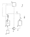
FIG. 1 , athermal control subsystem 10 for a fuel cell system located on an aircraft is illustrated. During operation, afuel cell stack 20 and the associated subsystems in direct or fluid communication with thefuel cell stack 20, are at an elevated temperature. For example, the operating temperature of a proton exchange membrane (PEM) fuel cell is commonly in the range of between about 60°C (333 Kelvin) and about 85°C (358 Kelvin). Therefore, the various subsystems in direct or fluid communication with thefuel cell stack 20 are similarly at an elevated temperature when the fuel cell system becomes idle. When the fuel cell system is in an idle state, assuming a sub-freezing ambient temperature, the various subsystems will cool rapidly. After a sufficiently long period of time, thefuel cell stack 20 will eventually cool to the sub-freezing ambient temperature. Positioned adjacent to or within thefuel cell stack 20 is a temperature sensor 44 connected to acontrol device 50 for monitoring the temperature of thestack 20. When the temperature of the idlefuel cell stack 20 falls below a selected threshold, thecontrol device 50 will shift the operation of the fuel cell system from an idle first mode to a second warming mode. An exemplary selected temperature threshold may be in the range of between about 4°C (277 Kelvin) and -10°C (263 Kelvin). More specifically, an exemplary selected temperature may be 0°C (273 Kelvin). The fuel cell stack may include a series of fuel cells stacked and held together by pressure plates. The temperature of thefuel cell stack 20 may vary from fuel cell to fuel cell. Typically, during a cooling process, the ends of thefuel cell stack 20 nearest the pressure plates cool more quickly than the center of thestack 20. Because of this, the temperature sensor 44 used to drive the control system may be arranged to measure the temperature of the coolest part of thefuel cell stack 20, such as at the fuel cells adjacent the pressure plates for example. - Multiple methods exist for warming a
fuel cell stack 20 in the second mode whereby a gas or a liquid is circulated throughsystem 10. In an embodiment, as shown inFIG. 1 , athermal control subsystem 10 increases the temperature of afuel cell stack 20 using warm air from another aircraft subsystem. Awarm air supply 30 is fluidly connected to an inlet 22 of thefuel cell stack 20 by aconduit 36. Exemplary sources that may act asair supply 30 include the airplane's air supply management system, cabin air, and engine bleed air. The temperature of the air provided by theair supply 30 may be up to about 95°C (368 Kelvin) depending on the source of the air. As the warm air A passes through thefuel cell stack 20, thermal energy is transferred from the air A to thefuel cell stack 20. The air A then exits throughoutlet 24 of thefuel cell stack 20 and is released inarea 60, such as a within another section of the aircraft or to the atmosphere, for example. In another embodiment, the air A may be returned to theair supply 30 from which it was taken by aconduit 38. Disposed along the fluid path between theoutlet 34 of theair supply 30 and the inlet 22 of thefuel cell stack 20 is avalve 42 operable between an open and a closed position. - In one embodiment, a
pump 40 is located along theconduit 38 for circulating the air from thefuel cell stack 20 back to theair supply 30. Thepump 40 and thevalve 42 are connected to acontrol device 50. Once a temperature sensor 44 determines that the temperature of thefuel cell stack 20 is below a selected threshold, thecontrol device 50 will begin to operate in the second mode by opening thevalve 42, so that air will flow from theair supply 30 to thefuel cell stack 20. In addition, thecontrol device 50 may run thepump 40 to circulate the cool air exiting thefuel cell stack 20 back to theair supply 30. In one embodiment, the warm air A is circulated around the outside of thefuel cell stack 20 rather than through it. For fuel cells constructed with porous bipolar plate technology, circulating warming air around the fuel cell, as opposed to through it, will prevent dehydration of the membrane. For fuel cells constructed with a solid bipolar plate technology, where the coolant loop is fluidly isolated from the membrane electrode assembly, the warm air may be circulated through the coolant channels of the fuel cell. Both solid plate and porous plate technology fuel cells may be warmed by circulating warm air around the outside of thefuel cell stack 20. - Referring now to
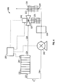
FIG. 2 , in yet another embodiment, athermal control subsystem 110 warms afuel cell stack 120 using one or more resistiveelectrical elements 160. The resistiveelectrical element 160 may be positioned adjacent thefuel cell stack 120 or alternately may be embedded within the end plates or pressure plates of thefuel cell stack 120. In one embodiment, the resistiveelectrical element 160 is a heater. In one embodiment,thermal insulation 180, such as an insulating jacket for example, surrounds thefuel cell stack 120. The thermal insulation will slow the cooling of the idlefuel cell stack 120 by retaining some of the heat generated during operation. Thethermal insulation 180 illustrated may be used in conjunction with any of the thermal control subsystems disclosed herein. When atemperature sensor 144 connected to thefuel cell stack 120 determines that the temperature of thefuel cell stack 120 has fallen below a selected threshold, thecontrol device 150 switches from a first mode to a second warming mode. In the second warming mode, thecontrol device 150 sends a signal to activate the resistiveelectrical element 160. In one embodiment, power is provided to the resistiveelectrical element 160 by apower source 170. Thepower source 170 is the electrical grid of the aircraft. In another embodiment, thepower source 170 is a battery. In yet another embodiment, when the aircraft is parked, ground power may be used to power the resistiveelectrical element 160. - Referring now to the exemplary
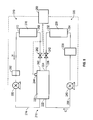
thermal control subsystem 210 ofFIG. 3 , anoutlet 224 of afuel cell stack 220 is fluidly connected to aninlet 232 of aheat exchanger 230 by afirst conduit 226. Similarly, asecond conduit 236 connects theoutlet 234 of theheat exchanger 230 with theinlet 222 of thefuel cell 220 to form a thermal management loop. In one embodiment, a fluid C, such as air or a coolant including water or antifreeze for example, circulates within the thermal management loop. If fluid C is antifreeze,thermal control subsystem 210 may not be applied to porous bipolar plate fuel cells. As illustrated, acontrol valve 242 is provided alongconduit 226 between theoutlet 224 of thefuel cell stack 220 and theinlet 232 of theheat exchanger 230. Thevalve 242 is operable between a first position and a second position to control the circulation of the fluid C within the thermal management loop. - Additionally a
bypass conduit 227 connectsconduit 226 toconduit 236 adjacent theheat exchanger 230 in order to redirect a flow of fluid. The end ofbypass conduit 227 is connected tovalve 242. In one embodiment,valve 242 is a three way valve such that when thefuel cell 220 is idle, the flow of fluid C may be redirected throughbypass conduit 227, rather than through theheat exchanger 230. The fluid C is circulated by apump 240 under control of thecontrol device 250. In one embodiment, the fluid C has a temperature generally in the range of between -10°C (263 Kelvin) and the temperature of thefuel cell 220. If water is used as a coolant fluid, the fluid C temperature would be limited to 0°C (273 Kelvin). Anaccumulator 238 may be provided upstream from thepump 240. In one embodiment, aheating device 239, such as a wire mesh heater for example, may be positioned within theaccumulator 238 to increase the temperature of the fluid C being circulated to thefuel cell stack 220. Thepump 240, thevalve 242, and theheating device 239 are operably coupled to thecontrol device 250. - It will be understood by a person of ordinary skill that this thermal management loop uses fluid C to transfer heat to the
fuel cell stack 220 from theheating device 239 when thefuel cell 220 is idling. When thefuel cell stack 220 is in normal operation and not idling, this samethermal management loop 210 may serve as a cooling loop that transfers thermal energy from thefuel cell stack 220 to the environment via theheat exchanger 230. When thetemperature sensor 244 embedded within thefuel cell stack 220 falls below a selected value, thecontrol device 250 may be programmed to operate theheating device 239 withinaccumulator 238, causing the fluid C to become heated. Additionally, thecontrol device 250 opens thevalve 242 at the end ofbypass conduit 227 and activates thepump 240 to circulate the fluid C through thefuel cell stack 220. Circulation of the fluid C will transfer thermal energy from theheating device 239 to thefuel cell stack 220. As the fluid C exits theoutlet 224 of thefuel cell stack 220, the cooled fluid C flows throughbypass conduit 227 and into theaccumulator 238 where the fluid C may be heated by theheating device 239. - In an alternate embodiment, illustrated in
FIG. 4 , thebypass conduit 227 ofthermal management system 210 includes aheat exchanger 229 rather than aheating device 239 while all other components remain substantially the same as the system shown and described with reference toFIG. 3 . Theheat exchanger 229 is located in a temperature controlled area of the aircraft, such as in the cabin for example. As the fluid C circulates through theheat exchanger 229, heat from the surrounding air will transfer to the fluid C. - The
thermal control subsystem 210 illustrated inFIG. 5 is a variation of the thermal control subsystem ofFIG. 4 for warming afuel cell stack 220. The fuel cell inFIG. 5 includes adedicated cooling loop 300 and a separate,dedicated heating loop 310. Theoutlet 224 of thefuel cell stack 220 is fluidly connected to aninlet 268 of aheat exchanger 270 by afirst conduit 260. Asecond conduit 274 connects theoutlet 272 of theheat exchanger 270 with theinlet 222 of thefuel cell stack 220 to form a heating loop. In one embodiment, theheat exchanger 270 is located in a temperature controlled area in the aircraft, such as in the cabin for example. A warming fluid H, such as water or air for example, circulates within theheating loop 310. A cooling fluid C, such as water for example, circulates within thecooling loop 300. Theheating loop 310 includes acontrol valve 262 and apump 280 for circulating the fluid H. Thecooling loop 300 includes acontrol valve 242 and apump 240 for circulating the fluid C. When thefuel cell 220 is in normal operation and generating heat,control valve 242 of thecooling loop 300 will be open and thecontrol valve 262 of theheating loop 310 will be closed. Opening ofcontrol valve 242 and operation ofpump 240 will circulate the cooling fluid C and will remove heat from thefuel cell 220. - During normal operation, heat from the
fuel cell 220 is released to the ambient atmosphere throughconduit 226 and theheat exchanger 230. In the illustrated embodiment, thecooling loop 300 does not include a bypass conduit, or a heating device disposed within theaccumulator 238. When thefuel cell 220 is idling and above a selected temperature threshold, bothcontrol valves heating loop 310 nor thecooling loop 300 is operating. When thetemperature sensor 244 detects that the temperature of thefuel cell stack 220 is below a selected threshold, thecontrol device 250 will initiate the operation of theheating loop 310 by openingcontrol valve 262 and runningpump 280 to circulate the fluid H through thefuel cell 220. As the cooled fluid H exits theoutlet 224 of thefuel cell stack 220, it passes throughheat exchanger 270, where heat is transferred to the fluid H from the surrounding environment. In embodiments where fluid H is water, theheating loop 310 may additionally include anaccumulator 282. - In another embodiment, the fuel cell stack of any of the prior embodiments may be warmed by operating the fuel cell at a low or minimum load. The heat produced as a byproduct of the electrochemical process of the fuel cell warms the fuel cell stack to a temperature above the minimum threshold. To warm the fuel cell stack using this method for long periods of time, a large supply source of both hydrogen and oxygen is required.
- For any of the disclosed embodiments, when the fuel cell is idle, power is required to operate the associated devices, such as a control device, a pump, or a heating device for example. Because the fuel cell is not generating power when it is idle, the power for the associated devices is supplied by an alternate source. Exemplary power sources include a battery, the power grid of the aircraft, ground power if the aircraft is parked, and any other means known to a person skilled in the art.
- Any of the embodiments of the invention discussed above may be applied to a fuel cell system of an aircraft individually or in combination with any of the other embodiments. For example, when the fuel cell system operates in a second mode, the fuel cell may operate at a minimum load and include a resistive electrical heating element. When applied together to the fuel cell system, the resistive electrical heating element may be driven using the electrical power generated by the fuel cell stack. In addition, a thermal insulation, such as an insulating jacket, may surround any of the fuel cell stacks in the previously described thermal control systems.
- While the invention has been described in detail in connection with only a limited number of embodiments, it should be readily understood that the invention is not limited to such disclosed embodiments. Rather, the invention can be modified to incorporate any number of variations, alterations, substitutions or equivalent arrangements not heretofore described, but which are commensurate with the scope of the invention. Additionally, while various embodiments of the invention have been described, it is to be understood that aspects of the invention may include only some of the described embodiments. Accordingly, the invention is not to be seen as limited by the foregoing description, but is only limited by the scope of the appended claims.
Claims (19)
- A system for warming a fuel cell on an aircraft, comprising:at least one fuel cell (20; 120; 220) including an anode and a cathode for creating electrical and thermal energy by an electrochemical reaction;at least one temperature sensor (44; 144; 244) for measuring a first temperature of the at least one fuel cell (20; 120; 220); anda control unit (50; 150; 250) electrically coupled to the at least one temperature sensor (44; 144; 244), the control unit (50; 150; 250) being configured for increasing the first temperature to a second temperature in response to the first temperature being at least equal to a selected temperature threshold;wherein the increasing of the first temperature is indicative of the control unit (50; 150; 250) operating the fuel cell (20; 120; 220) in a warming mode; andwherein the second temperature is higher than the selected temperature threshold.
- The system according to claim 1, wherein the selected temperature threshold is generally in the range of between about 4°C and about -10°C, for example generally about 0°C.
- The system according to claim 1 or 2, wherein the control unit (50; 150; 250) is configured to increase the temperature while the aircraft is in flight, on ground, and during aircraft parking.
- The system according to any preceding claim, wherein the warming mode includes operating the fuel cell (20; 120; 220) at a low load to increase the temperature of the fuel cell (20; 120; 220).
- The system according to any preceding claim, wherein the warming mode comprises regulating a temperature of an environment of the fuel cell (20; 120; 220).
- The system according to claim 5, further comprising a warm air or fluid supply in fluid communication with the fuel cell (20; 120; 220) for heating the environment of the fuel cell (20; 120; 220).
- The subsystem according to claim 6, wherein the warm fluid is supplied from an aircraft subsystem, for example at a temperature generally in the range of between about -10°C and about 95°C.
- The system according to claim 5, 6 or 7, wherein the temperature of the environment of the fuel cell is regulated using a resistive electrical element (160; 239) in fluid communication with a fluid in the fuel cell (120; 220).
- The system according to any of claims 5 to 8, further comprising a heat exchanger (230; 270) in fluid communication with the fuel cell (220) for heating the environment of the fuel cell (220).
- A method of operating a fuel cell (20; 120; 220) on an aircraft, the fuel cell (20; 120; 220) operatively coupled to at least one sensor (44; 144; 244), comprising:sensing a temperature of the fuel cell (20; 120; 220) with the at least one sensor (44; 144; 244); andoperating the fuel cell (20; 120; 220) in a first mode if the sensed temperature is above a selected temperature threshold and operating the fuel cell (20; 120; 220) in a second mode if the sensed temperature is less than or equal to the selected temperature threshold.
- The method according to claim 10, wherein the selected temperature threshold is generally in the range of between about 4°C and about -10°C, for example generally about 0°C.
- The method according to claim 10 or 11, wherein operating in the second mode comprises operating the fuel cell (20; 120; 220) at a low load to increase the temperature of the fuel cell.
- The method according to claim 10, 11 or 12, wherein operating in the second mode further comprises regulating a temperature of an environment of the fuel cell.
- The method according to any of claims 10 to 13 further comprising circulating a warm fluid through the environment of the fuel cell (20, 120, 220), for example at a temperature generally in the range of between about -10°C and about 95°C.
- The method of according to claim 14, further comprising supplying the warm fluid from an aircraft subsystem
- The method according to claim 15, further comprising supplying the warm fluid with an air supply within the aircraft.
- The method according to claim 15 or 16, wherein the warm fluid is a coolant stored within a cooling loop (300) of the fuel cell.
- The method according to any of claims 13 to 17, further comprising regulating the temperature of the environment with a resistive electrical heating element (160; 239).
- The system or method according to any preceding claim, wherein power for operating the fuel cell (20; 120; 220) in the warming mode is supplied by one of an electrical grid of the aircraft, a ground power source, or a battery.
Applications Claiming Priority (1)
| Application Number | Priority Date | Filing Date | Title |
|---|---|---|---|
| US13/457,850 US9472819B2 (en) | 2012-04-27 | 2012-04-27 | Warming feature for aircraft fuel cells |
Publications (3)
| Publication Number | Publication Date |
|---|---|
| EP2658022A2 true EP2658022A2 (en) | 2013-10-30 |
| EP2658022A3 EP2658022A3 (en) | 2016-11-09 |
| EP2658022B1 EP2658022B1 (en) | 2021-10-20 |
Family
ID=48227002
Family Applications (1)
| Application Number | Title | Priority Date | Filing Date |
|---|---|---|---|
| EP13165645.6A Active EP2658022B1 (en) | 2012-04-27 | 2013-04-26 | Warming feature for aircraft fuel cells |
Country Status (2)
| Country | Link |
|---|---|
| US (2) | US9472819B2 (en) |
| EP (1) | EP2658022B1 (en) |
Cited By (3)
| Publication number | Priority date | Publication date | Assignee | Title |
|---|---|---|---|---|
| WO2015104487A1 (en) | 2014-01-10 | 2015-07-16 | Snecma | Emergency electrical generator of an aircraft, with a quick-starting fuel cell |
| TWI563856B (en) * | 2014-02-27 | 2016-12-21 | Merry Electronics Co Ltd | Mobile device and corresponding noise-canceling earphone |
| WO2017046640A1 (en) * | 2015-09-19 | 2017-03-23 | Daimler Ag | Shutdown and storage method for fuel cell system at below freezing temperatures |
Families Citing this family (5)
| Publication number | Priority date | Publication date | Assignee | Title |
|---|---|---|---|---|
| US9472819B2 (en) | 2012-04-27 | 2016-10-18 | Hamilton Sundstrand Corporation | Warming feature for aircraft fuel cells |
| DE102015100186A1 (en) * | 2015-01-08 | 2016-07-14 | Airbus Operations Gmbh | Fuel cell system, a method for heating such a system and an aircraft with such a system |
| US10480446B2 (en) * | 2015-07-16 | 2019-11-19 | Ge Aviation Systems Llc | Method and apparatus for cooling a heat-generating module |
| US20190041145A1 (en) | 2017-08-01 | 2019-02-07 | Hamilton Sundstrand Corporation | Three-way modulating valve for temperature control |
| CN108155403A (en) * | 2018-01-18 | 2018-06-12 | 深圳国氢新能源科技有限公司 | A kind of fuel cell system and its guard method |
Family Cites Families (18)
| Publication number | Priority date | Publication date | Assignee | Title |
|---|---|---|---|---|
| US7482085B2 (en) * | 1996-06-07 | 2009-01-27 | Bdf Ip Holdings Ltd. | Apparatus for improving the cold starting capability of an electrochemical fuel cell |
| US6248462B1 (en) * | 1999-05-28 | 2001-06-19 | International Fuel Cells, Llc | Method and apparatus for thermal management of a fuel cell assembly |
| US7223490B2 (en) | 2001-04-06 | 2007-05-29 | Honda Giken Kogyo Kabushiki Kaisha | Fuel cell employing local power generation when starting at low temperature |
| US7264895B2 (en) * | 2001-10-31 | 2007-09-04 | Plug Power Inc. | Fuel cell thermal management system |
| US6797421B2 (en) * | 2002-01-11 | 2004-09-28 | Utc Fuel Cells, Llc | Method and apparatus for preventing water in fuel cell power plants from freezing during storage |
| US6955861B2 (en) | 2002-02-27 | 2005-10-18 | Nissan Motor Co., Ltd. | Fuel cell system, and method of protecting a fuel cell from freezing |
| JP4221942B2 (en) | 2002-03-27 | 2009-02-12 | 日産自動車株式会社 | Fuel cell system |
| JP4151384B2 (en) * | 2002-11-07 | 2008-09-17 | 日産自動車株式会社 | Fuel cell system |
| US7169493B2 (en) | 2003-04-30 | 2007-01-30 | Proton Energy Systems, Inc. | Fuel cell system with thermal management and method of operation thereof |
| JP2004342430A (en) * | 2003-05-15 | 2004-12-02 | Toyota Motor Corp | Fuel cell system and its operation method |
| US20080020250A1 (en) * | 2003-11-05 | 2008-01-24 | Walter Schuetz | Storage System for Storing a Medium and Method for Loading a Storage System With a Storage Medium and Emptying the Same Therefrom |
| DE102005010399B4 (en) * | 2005-03-07 | 2010-08-05 | Airbus Deutschland Gmbh | Aircraft with a fuel cell emergency system and method for external air independent emergency power supply |
| DE102005051583A1 (en) * | 2005-10-27 | 2007-05-03 | Airbus Deutschland Gmbh | Fuel cell system for the supply of aircraft |
| US20070178347A1 (en) * | 2006-01-27 | 2007-08-02 | Siepierski James S | Coolant bypass for fuel cell stack |
| US8034500B2 (en) | 2007-05-30 | 2011-10-11 | Idatech, Llc | Systems and methods for starting and operating fuel cell systems in subfreezing temperatures |
| DE102007046381B4 (en) * | 2007-09-27 | 2011-07-28 | Airbus Operations GmbH, 21129 | Fuel cell system with suction for an aircraft, method for operating the fuel cell system and aircraft with such a fuel cell system |
| DE102007060428B3 (en) * | 2007-12-14 | 2009-05-07 | Airbus Deutschland Gmbh | Fuel cell system i.e. evaporation-cooled fuel cell system, for use in aircraft, has control unit controlling temperature of cell, where cooling agent is transferred into gaseous state in aggregate condition |
| US9472819B2 (en) | 2012-04-27 | 2016-10-18 | Hamilton Sundstrand Corporation | Warming feature for aircraft fuel cells |
-
2012
- 2012-04-27 US US13/457,850 patent/US9472819B2/en active Active
-
2013
- 2013-04-26 EP EP13165645.6A patent/EP2658022B1/en active Active
-
2016
- 2016-09-13 US US15/263,662 patent/US10135081B2/en active Active
Non-Patent Citations (1)
| Title |
|---|
| None |
Cited By (5)
| Publication number | Priority date | Publication date | Assignee | Title |
|---|---|---|---|---|
| WO2015104487A1 (en) | 2014-01-10 | 2015-07-16 | Snecma | Emergency electrical generator of an aircraft, with a quick-starting fuel cell |
| FR3016345A1 (en) * | 2014-01-10 | 2015-07-17 | Snecma | EMERGENCY POWER GENERATOR WITH FAST STARTER FUEL CELL |
| TWI563856B (en) * | 2014-02-27 | 2016-12-21 | Merry Electronics Co Ltd | Mobile device and corresponding noise-canceling earphone |
| WO2017046640A1 (en) * | 2015-09-19 | 2017-03-23 | Daimler Ag | Shutdown and storage method for fuel cell system at below freezing temperatures |
| US10547067B2 (en) | 2015-09-19 | 2020-01-28 | Daimler Ag | Shutdown and storage method for fuel cell system at below freezing temperatures |
Also Published As
| Publication number | Publication date |
|---|---|
| EP2658022B1 (en) | 2021-10-20 |
| US9472819B2 (en) | 2016-10-18 |
| US20160380288A1 (en) | 2016-12-29 |
| US20130288082A1 (en) | 2013-10-31 |
| US10135081B2 (en) | 2018-11-20 |
| EP2658022A3 (en) | 2016-11-09 |
Similar Documents
| Publication | Publication Date | Title |
|---|---|---|
| US10135081B2 (en) | Warming feature for aircraft fuel cells | |
| CN110957503B (en) | Air heating reflux system for low-temperature starting of fuel cell and control method | |
| US10249890B2 (en) | Method for cold-start of fuel cell stack | |
| US6673481B1 (en) | Initiating operation of an electric vehicle or other load powered by a fuel cell at sub-freezing temperature | |
| US8168343B2 (en) | Humidification control during shutdown of a fuel cell system | |
| US7455920B2 (en) | Fuel cell system | |
| US8431282B2 (en) | Closed coolant loop with expansion device for a fuel cell system | |
| JP5324756B2 (en) | Multi-pressure controlled control to minimize RH excursion during transients | |
| US20050202293A1 (en) | Fuel cell conditioning system and related method | |
| CN107251295B (en) | Coolant injection controller for fuel cell system | |
| JP2017195021A (en) | Fuel cell system | |
| US20110081588A1 (en) | Method and apparatus for pem fuel cell freezing protection | |
| US20070178347A1 (en) | Coolant bypass for fuel cell stack | |
| KR102506850B1 (en) | Fuel cell symtem | |
| JP2008059922A (en) | Fuel cell system | |
| JP2017147135A (en) | Control method for fuel cell system | |
| CN107210461B (en) | Fuel cell and coolant storage | |
| KR102447071B1 (en) | Method for operating fuel cell and controller therefor | |
| EP1913652B1 (en) | Thermal control of fuel cell for improved cold start | |
| JP2005322527A (en) | Fuel cell system | |
| JP5287368B2 (en) | Fuel cell system | |
| JP7422122B2 (en) | fuel cell system | |
| JP7416011B2 (en) | Fuel cell system and aircraft | |
| US7381489B2 (en) | PEM fuel cell with high porosity hydrophilic water transport plates and temperature increase before shutdown in environment which may reach subfreezing temperatures | |
| JP4814508B2 (en) | Fuel cell system |
Legal Events
| Date | Code | Title | Description |
|---|---|---|---|
| PUAI | Public reference made under article 153(3) epc to a published international application that has entered the european phase |
Free format text: ORIGINAL CODE: 0009012 |
|
| AK | Designated contracting states |
Kind code of ref document: A2 Designated state(s): AL AT BE BG CH CY CZ DE DK EE ES FI FR GB GR HR HU IE IS IT LI LT LU LV MC MK MT NL NO PL PT RO RS SE SI SK SM TR |
|
| AX | Request for extension of the european patent |
Extension state: BA ME |
|
| PUAL | Search report despatched |
Free format text: ORIGINAL CODE: 0009013 |
|
| AK | Designated contracting states |
Kind code of ref document: A3 Designated state(s): AL AT BE BG CH CY CZ DE DK EE ES FI FR GB GR HR HU IE IS IT LI LT LU LV MC MK MT NL NO PL PT RO RS SE SI SK SM TR |
|
| AX | Request for extension of the european patent |
Extension state: BA ME |
|
| RIC1 | Information provided on ipc code assigned before grant |
Ipc: H01M 8/04 20060101AFI20161006BHEP Ipc: B64D 41/00 20060101ALI20161006BHEP |
|
| STAA | Information on the status of an ep patent application or granted ep patent |
Free format text: STATUS: REQUEST FOR EXAMINATION WAS MADE |
|
| 17P | Request for examination filed |
Effective date: 20170509 |
|
| RBV | Designated contracting states (corrected) |
Designated state(s): AL AT BE BG CH CY CZ DE DK EE ES FI FR GB GR HR HU IE IS IT LI LT LU LV MC MK MT NL NO PL PT RO RS SE SI SK SM TR |
|
| STAA | Information on the status of an ep patent application or granted ep patent |
Free format text: STATUS: EXAMINATION IS IN PROGRESS |
|
| 17Q | First examination report despatched |
Effective date: 20180222 |
|
| STAA | Information on the status of an ep patent application or granted ep patent |
Free format text: STATUS: EXAMINATION IS IN PROGRESS |
|
| REG | Reference to a national code |
Ref country code: DE Ref legal event code: R079 Ref document number: 602013079699 Country of ref document: DE Free format text: PREVIOUS MAIN CLASS: H01M0008040000 Ipc: H01M0008042230 |
|
| GRAP | Despatch of communication of intention to grant a patent |
Free format text: ORIGINAL CODE: EPIDOSNIGR1 |
|
| STAA | Information on the status of an ep patent application or granted ep patent |
Free format text: STATUS: GRANT OF PATENT IS INTENDED |
|
| RIC1 | Information provided on ipc code assigned before grant |
Ipc: H01M 8/04701 20160101ALI20210413BHEP Ipc: H01M 8/0432 20160101ALI20210413BHEP Ipc: B64D 41/00 20060101ALI20210413BHEP Ipc: H01M 8/04029 20160101ALI20210413BHEP Ipc: H01M 8/04223 20160101AFI20210413BHEP |
|
| INTG | Intention to grant announced |
Effective date: 20210511 |
|
| RAP3 | Party data changed (applicant data changed or rights of an application transferred) |
Owner name: HAMILTON SUNDSTRAND CORPORATION |
|
| GRAS | Grant fee paid |
Free format text: ORIGINAL CODE: EPIDOSNIGR3 |
|
| GRAA | (expected) grant |
Free format text: ORIGINAL CODE: 0009210 |
|
| STAA | Information on the status of an ep patent application or granted ep patent |
Free format text: STATUS: THE PATENT HAS BEEN GRANTED |
|
| AK | Designated contracting states |
Kind code of ref document: B1 Designated state(s): AL AT BE BG CH CY CZ DE DK EE ES FI FR GB GR HR HU IE IS IT LI LT LU LV MC MK MT NL NO PL PT RO RS SE SI SK SM TR |
|
| REG | Reference to a national code |
Ref country code: GB Ref legal event code: FG4D |
|
| REG | Reference to a national code |
Ref country code: CH Ref legal event code: EP |
|
| REG | Reference to a national code |
Ref country code: DE Ref legal event code: R096 Ref document number: 602013079699 Country of ref document: DE |
|
| REG | Reference to a national code |
Ref country code: IE Ref legal event code: FG4D |
|
| REG | Reference to a national code |
Ref country code: AT Ref legal event code: REF Ref document number: 1440660 Country of ref document: AT Kind code of ref document: T Effective date: 20211115 |
|
| REG | Reference to a national code |
Ref country code: LT Ref legal event code: MG9D |
|
| REG | Reference to a national code |
Ref country code: NL Ref legal event code: MP Effective date: 20211020 |
|
| REG | Reference to a national code |
Ref country code: AT Ref legal event code: MK05 Ref document number: 1440660 Country of ref document: AT Kind code of ref document: T Effective date: 20211020 |
|
| PG25 | Lapsed in a contracting state [announced via postgrant information from national office to epo] |
Ref country code: RS Free format text: LAPSE BECAUSE OF FAILURE TO SUBMIT A TRANSLATION OF THE DESCRIPTION OR TO PAY THE FEE WITHIN THE PRESCRIBED TIME-LIMIT Effective date: 20211020 Ref country code: LT Free format text: LAPSE BECAUSE OF FAILURE TO SUBMIT A TRANSLATION OF THE DESCRIPTION OR TO PAY THE FEE WITHIN THE PRESCRIBED TIME-LIMIT Effective date: 20211020 Ref country code: FI Free format text: LAPSE BECAUSE OF FAILURE TO SUBMIT A TRANSLATION OF THE DESCRIPTION OR TO PAY THE FEE WITHIN THE PRESCRIBED TIME-LIMIT Effective date: 20211020 Ref country code: BG Free format text: LAPSE BECAUSE OF FAILURE TO SUBMIT A TRANSLATION OF THE DESCRIPTION OR TO PAY THE FEE WITHIN THE PRESCRIBED TIME-LIMIT Effective date: 20220120 Ref country code: AT Free format text: LAPSE BECAUSE OF FAILURE TO SUBMIT A TRANSLATION OF THE DESCRIPTION OR TO PAY THE FEE WITHIN THE PRESCRIBED TIME-LIMIT Effective date: 20211020 |
|
| PG25 | Lapsed in a contracting state [announced via postgrant information from national office to epo] |
Ref country code: IS Free format text: LAPSE BECAUSE OF FAILURE TO SUBMIT A TRANSLATION OF THE DESCRIPTION OR TO PAY THE FEE WITHIN THE PRESCRIBED TIME-LIMIT Effective date: 20220220 Ref country code: SE Free format text: LAPSE BECAUSE OF FAILURE TO SUBMIT A TRANSLATION OF THE DESCRIPTION OR TO PAY THE FEE WITHIN THE PRESCRIBED TIME-LIMIT Effective date: 20211020 Ref country code: PT Free format text: LAPSE BECAUSE OF FAILURE TO SUBMIT A TRANSLATION OF THE DESCRIPTION OR TO PAY THE FEE WITHIN THE PRESCRIBED TIME-LIMIT Effective date: 20220221 Ref country code: PL Free format text: LAPSE BECAUSE OF FAILURE TO SUBMIT A TRANSLATION OF THE DESCRIPTION OR TO PAY THE FEE WITHIN THE PRESCRIBED TIME-LIMIT Effective date: 20211020 Ref country code: NO Free format text: LAPSE BECAUSE OF FAILURE TO SUBMIT A TRANSLATION OF THE DESCRIPTION OR TO PAY THE FEE WITHIN THE PRESCRIBED TIME-LIMIT Effective date: 20220120 Ref country code: NL Free format text: LAPSE BECAUSE OF FAILURE TO SUBMIT A TRANSLATION OF THE DESCRIPTION OR TO PAY THE FEE WITHIN THE PRESCRIBED TIME-LIMIT Effective date: 20211020 Ref country code: LV Free format text: LAPSE BECAUSE OF FAILURE TO SUBMIT A TRANSLATION OF THE DESCRIPTION OR TO PAY THE FEE WITHIN THE PRESCRIBED TIME-LIMIT Effective date: 20211020 Ref country code: HR Free format text: LAPSE BECAUSE OF FAILURE TO SUBMIT A TRANSLATION OF THE DESCRIPTION OR TO PAY THE FEE WITHIN THE PRESCRIBED TIME-LIMIT Effective date: 20211020 Ref country code: GR Free format text: LAPSE BECAUSE OF FAILURE TO SUBMIT A TRANSLATION OF THE DESCRIPTION OR TO PAY THE FEE WITHIN THE PRESCRIBED TIME-LIMIT Effective date: 20220121 Ref country code: ES Free format text: LAPSE BECAUSE OF FAILURE TO SUBMIT A TRANSLATION OF THE DESCRIPTION OR TO PAY THE FEE WITHIN THE PRESCRIBED TIME-LIMIT Effective date: 20211020 |
|
| REG | Reference to a national code |
Ref country code: DE Ref legal event code: R097 Ref document number: 602013079699 Country of ref document: DE |
|
| PG25 | Lapsed in a contracting state [announced via postgrant information from national office to epo] |
Ref country code: SM Free format text: LAPSE BECAUSE OF FAILURE TO SUBMIT A TRANSLATION OF THE DESCRIPTION OR TO PAY THE FEE WITHIN THE PRESCRIBED TIME-LIMIT Effective date: 20211020 Ref country code: SK Free format text: LAPSE BECAUSE OF FAILURE TO SUBMIT A TRANSLATION OF THE DESCRIPTION OR TO PAY THE FEE WITHIN THE PRESCRIBED TIME-LIMIT Effective date: 20211020 Ref country code: RO Free format text: LAPSE BECAUSE OF FAILURE TO SUBMIT A TRANSLATION OF THE DESCRIPTION OR TO PAY THE FEE WITHIN THE PRESCRIBED TIME-LIMIT Effective date: 20211020 Ref country code: EE Free format text: LAPSE BECAUSE OF FAILURE TO SUBMIT A TRANSLATION OF THE DESCRIPTION OR TO PAY THE FEE WITHIN THE PRESCRIBED TIME-LIMIT Effective date: 20211020 Ref country code: DK Free format text: LAPSE BECAUSE OF FAILURE TO SUBMIT A TRANSLATION OF THE DESCRIPTION OR TO PAY THE FEE WITHIN THE PRESCRIBED TIME-LIMIT Effective date: 20211020 Ref country code: CZ Free format text: LAPSE BECAUSE OF FAILURE TO SUBMIT A TRANSLATION OF THE DESCRIPTION OR TO PAY THE FEE WITHIN THE PRESCRIBED TIME-LIMIT Effective date: 20211020 |
|
| PLBE | No opposition filed within time limit |
Free format text: ORIGINAL CODE: 0009261 |
|
| STAA | Information on the status of an ep patent application or granted ep patent |
Free format text: STATUS: NO OPPOSITION FILED WITHIN TIME LIMIT |
|
| 26N | No opposition filed |
Effective date: 20220721 |
|
| PG25 | Lapsed in a contracting state [announced via postgrant information from national office to epo] |
Ref country code: AL Free format text: LAPSE BECAUSE OF FAILURE TO SUBMIT A TRANSLATION OF THE DESCRIPTION OR TO PAY THE FEE WITHIN THE PRESCRIBED TIME-LIMIT Effective date: 20211020 |
|
| PG25 | Lapsed in a contracting state [announced via postgrant information from national office to epo] |
Ref country code: SI Free format text: LAPSE BECAUSE OF FAILURE TO SUBMIT A TRANSLATION OF THE DESCRIPTION OR TO PAY THE FEE WITHIN THE PRESCRIBED TIME-LIMIT Effective date: 20211020 |
|
| REG | Reference to a national code |
Ref country code: CH Ref legal event code: PL |
|
| GBPC | Gb: european patent ceased through non-payment of renewal fee |
Effective date: 20220426 |
|
| REG | Reference to a national code |
Ref country code: BE Ref legal event code: MM Effective date: 20220430 |
|
| PG25 | Lapsed in a contracting state [announced via postgrant information from national office to epo] |
Ref country code: MC Free format text: LAPSE BECAUSE OF FAILURE TO SUBMIT A TRANSLATION OF THE DESCRIPTION OR TO PAY THE FEE WITHIN THE PRESCRIBED TIME-LIMIT Effective date: 20211020 Ref country code: LU Free format text: LAPSE BECAUSE OF NON-PAYMENT OF DUE FEES Effective date: 20220426 Ref country code: LI Free format text: LAPSE BECAUSE OF NON-PAYMENT OF DUE FEES Effective date: 20220430 Ref country code: GB Free format text: LAPSE BECAUSE OF NON-PAYMENT OF DUE FEES Effective date: 20220426 Ref country code: CH Free format text: LAPSE BECAUSE OF NON-PAYMENT OF DUE FEES Effective date: 20220430 |
|
| PG25 | Lapsed in a contracting state [announced via postgrant information from national office to epo] |
Ref country code: BE Free format text: LAPSE BECAUSE OF NON-PAYMENT OF DUE FEES Effective date: 20220430 |
|
| PG25 | Lapsed in a contracting state [announced via postgrant information from national office to epo] |
Ref country code: IE Free format text: LAPSE BECAUSE OF NON-PAYMENT OF DUE FEES Effective date: 20220426 |
|
| PGFP | Annual fee paid to national office [announced via postgrant information from national office to epo] |
Ref country code: FR Payment date: 20230321 Year of fee payment: 11 |
|
| PG25 | Lapsed in a contracting state [announced via postgrant information from national office to epo] |
Ref country code: IT Free format text: LAPSE BECAUSE OF FAILURE TO SUBMIT A TRANSLATION OF THE DESCRIPTION OR TO PAY THE FEE WITHIN THE PRESCRIBED TIME-LIMIT Effective date: 20211020 |
|
| P01 | Opt-out of the competence of the unified patent court (upc) registered |
Effective date: 20230522 |
|
| PGFP | Annual fee paid to national office [announced via postgrant information from national office to epo] |
Ref country code: DE Payment date: 20230321 Year of fee payment: 11 |
|
| PG25 | Lapsed in a contracting state [announced via postgrant information from national office to epo] |
Ref country code: HU Free format text: LAPSE BECAUSE OF FAILURE TO SUBMIT A TRANSLATION OF THE DESCRIPTION OR TO PAY THE FEE WITHIN THE PRESCRIBED TIME-LIMIT; INVALID AB INITIO Effective date: 20130426 |
|
| PG25 | Lapsed in a contracting state [announced via postgrant information from national office to epo] |
Ref country code: MK Free format text: LAPSE BECAUSE OF FAILURE TO SUBMIT A TRANSLATION OF THE DESCRIPTION OR TO PAY THE FEE WITHIN THE PRESCRIBED TIME-LIMIT Effective date: 20211020 Ref country code: CY Free format text: LAPSE BECAUSE OF FAILURE TO SUBMIT A TRANSLATION OF THE DESCRIPTION OR TO PAY THE FEE WITHIN THE PRESCRIBED TIME-LIMIT Effective date: 20211020 |