EP2657749A1 - Microscope apparatus - Google Patents
Microscope apparatus Download PDFInfo
- Publication number
- EP2657749A1 EP2657749A1 EP13002197.5A EP13002197A EP2657749A1 EP 2657749 A1 EP2657749 A1 EP 2657749A1 EP 13002197 A EP13002197 A EP 13002197A EP 2657749 A1 EP2657749 A1 EP 2657749A1
- Authority
- EP
- European Patent Office
- Prior art keywords
- stage
- revolver
- electric
- microscope apparatus
- objective lens
- Prior art date
- Legal status (The legal status is an assumption and is not a legal conclusion. Google has not performed a legal analysis and makes no representation as to the accuracy of the status listed.)
- Granted
Links
Images






Classifications
-
- G—PHYSICS
- G02—OPTICS
- G02B—OPTICAL ELEMENTS, SYSTEMS OR APPARATUS
- G02B21/00—Microscopes
- G02B21/24—Base structure
- G02B21/248—Base structure objective (or ocular) turrets
-
- G—PHYSICS
- G02—OPTICS
- G02B—OPTICAL ELEMENTS, SYSTEMS OR APPARATUS
- G02B21/00—Microscopes
- G02B21/24—Base structure
-
- G—PHYSICS
- G02—OPTICS
- G02B—OPTICAL ELEMENTS, SYSTEMS OR APPARATUS
- G02B21/00—Microscopes
- G02B21/24—Base structure
- G02B21/241—Devices for focusing
Definitions
- the present invention relates to a microscope apparatus.
- Microscope apparatuses capable of observing a magnified image of a fine specimen and recording the observation image as a picture or a video image have been used in a wide variety of fields such as biological fields or industrial fields.
- the microscope apparatuses have been used for observing microstructures of a metal or used as an inspection apparatus in a process of manufacturing a semiconductor device or an LCD (liquid crystal display).
- the microscope apparatus is used for the above-described various fields, in many cases, components thereof are configured as units, so that the microscope apparatus may be used in various uses according to a combination of the units.
- the movable device in some cases, if the movable device is manipulated carelessly, the movable device becomes to be contacted with other device.
- the electric movable device can be operated by simple manipulation, even in the state where contact may occur if there is no method of preventing the contact, the electric movable device performs the associated operation as it is.
- the objective lens since the objective lens is inserted into an aperture of the stage, it is difficult for a user to determine the occurrence of contact. If switching of the electric revolver is manipulated carelessly, the objective lens becomes to be contacted with the specimen or the stage, so that the specimen or the objective lens may be destructed.
- a technique for a safe observation which can be performed by rotating an electric revolver after recessing the position of a focusing device or a stage in the case of an objective lens becomes to be contacted with the stage.
- the contact can be decided by the information of the position of the focusing device and the stage obtained by tracing a rotation trajectory of the objective lens.
- an object of the present invention is to provide a microscope apparatus capable of preventing contact of an electric movable device with the other devices when the electric movable device is operated, with a simple configuration and control.
- a microscope apparatus includes a stage on which a specimen is mounted, a revolver that holds a plurality of objective lenses and is configured to cause one of the plurality of objective lenses to be arranged on an observation light axis by a revolving motion. At least one of the stage and the revolver constitutes an electric movable device that is electrically operated.
- the microscope apparatus further includes an input device configured to input a command for operating the electric movable device; a manual focusing device configured to adjust a relative distance between the stage and the objective lenses; an operation control device configured to control operation of the electric movable device; a state determining device configured to determine that the electric movable device is in an operable state when the objective lenses and the stage are separated by a specified interval or more and to determine that the electric movable device is in an inoperable state when the objective lenses and the stage are separated by less than the specified interval; and a restriction device configured to restrict an output of a control signal for commanding the operation to the operation control device when the command for operating the electric movable device is input by the input device if the state determining device determines that the electric movable device is in the inoperable state.
- FIG. 1 is a schematic diagram of a configuration of an inverted microscope apparatus according to a first embodiment of the present invention.
- the inverted microscope apparatus includes a microscope main body 1, a stage 3 on which a specimen 2 is mounted, an electric revolver 5 which holds a plurality of objective lenses 4 and which is configured to electrically cause selected one of the objective lenses 4 to be arranged on an observation light axis, and a manual focusing device 6 which supports the electric revolver 5 and which is configured to adjust a distance between the specimen 2 (stage 3) and the objective lens 4.
- the electric revolver 5 is fixed to the manual focusing device 6 by fastener members (not illustrated) such as bolts.
- a user rotates a focusing handle 9 to lift up and down the manual focusing device 6 so that the distance between the specimen 2 and the objective lens 4 can be adjusted.
- the electric revolver 5 is replaceable with a manual revolver 5A as illustrated in FIG. 2 . That is, the electric revolver 5 and the manual revolver 5A can be replaced with one another by a user depending on an observation method.
- the electric revolver 5 is mounted in a non-removable manner, it is also considered to be "replaced" at the case in which the manual focusing device 6 is provided and the manual revolver 5A is attachable to it.
- the stage 3 is fixed to the microscope main body 1 by fastener members (not illustrated) such as bolts.
- the stage 3 is configured to include a lower plate 10, a middle plate 11, and an upper plate 12.
- the lower plate 10, the middle plate 11, and the upper plate 12 have respective apertures 10a, 11a, and 12a having different sizes.
- the objective lens 4 is inserted into the apertures 10a, 11a, and 12a, so that the distance between the objective lens 4 and the specimen 2 is adjusted.
- the stage 3 according to the first embodiment may be used in a manual or electric manner. If the sizes of stages having different sizes are within a specified range, any one of the stages can be used as the stage 3 attached in the microscope main body 1.
- the electric revolver 5 is configured to include a microswitch 13 as a state determining device.
- the microswitch 13 is a mechanical switch and is arranged on the bottom surface of the electric revolver 5.
- a protrusion 14 is installed in the microscope main body 1 at the position facing the microswitch 13. If the manual focusing device 6 is lifted down by rotation of the focusing handle 9, the microswitch 13 is pressed by the protrusion 14. Alternatively, the protrusion 14 may be removed, and the microswitch 13 may be configured to be in a protruded shape. Furthermore, the microswitch 13 may be formed in a protruded shape in the microscope main body 1, and the microswitch 13 may be configured to be pressed by lifting down the electric revolver 5. In addition, besides the microswitch 13, a photo-interrupter, a capacitive sensor, or the like may be used as the state determining device.
- a revolver operation control device 7 controls operations of the electric revolver 5. If the user selects the objective lens 4 held by the electric revolver 5 through a below-described input device 15, the revolver operation control device 7 controls the operations of the electric revolver 5 so that the selected objective lens 4 is inserted under the specimen 2.
- the revolver operation control device 7 may be built in the electric revolver 5 or be formed integrally with a below-described controller 8.
- the controller 8 is connected to the revolver operation control device 7, the input device 15, and an output device 16.
- the controller 8 functions as a restriction device. If the microswitch 13 is not pressed, even when the objective lens 4 is selected by a below-described input device 15, the controller 8 restricts transmission of information on the selection of the objective lens 4 to the revolver operation control device 7.
- a PC may be used as the controller 8.
- the restriction of the switching between the objective lenses 4 in the revolver operation control device 7 by the controller 8 may be selectively lifted. Therefore, user's convenience can be improved.
- the input device 15 is configured to input a command for selecting one of the objective lenses 4 held by the electric revolver 5.
- the selective input may be performed, for example, by a mechanical switch, a touch panel, or the like.
- the selective input may be made for selecting an objective lens directly or for commanding some divisions of rotation from a current position of the objective lens to the right or left position.
- the output device 16 outputs the type of the selected objective lens 4 or the hole number of the electric revolver 5 and outputs the signal whether or not the objective lens 4 selected by the input device 15 contacts with the stage 3.
- an LED or a display may be used as the output device 16.
- a buzzer may be used as the output device 16.
- a plurality of LEDs or buzzers may be used as the output device 16.
- FIG. 3 is a flowchart of a switching operation between the objective lenses 4 according to the first embodiment of the present invention.
- FIGS. 4 and 5 are diagrams illustrating the contact of the objective lens 4 with the stage 3 in the inverted microscope apparatus illustrated in FIG. 1 .
- the objective lens 4 is selected using the input device 15 (Step S101).
- the controller 8 determines whether or not the switching restriction of the objective lenses 4 is valid (Step S102). If the switching restriction of the objective lens 4 is not valid (No in Step S102), the controller 8 transmits the information on the selection of the objective lens 4 selected in Step S101 to the revolver operation control device 7 (Step S103), and the revolver operation control device 7 receives the information on the selection of the objective lens and controls the electric revolver 5 to insert the selected objective lens 4 under the specimen 2 to switch to the objective lens 4 (Step S104).
- Step S105 If the switching restriction of the objective lens 4 is valid (Yes in Step S102), the controller 8 determines whether or not the microswitch 13 is pressed (Step S105).
- Step S105 If the microswitch 13 is not pressed (No in Step S105), the objective lens 4 inserted under the specimen 2 and the stage 3 are separated from each other by less than a specified interval. If the electric revolver 5 is operated in this state, the objective lens 4 becomes to be contacted with the stage 3 due to a rotation trajectory 20 of the objective lens 4 indicated by a dotted line illustrated in FIG. 4 . Therefore, it is determined that the electric revolver 5 is in an inoperable state, so that the controller 8 ends the operation of switching between the objective lenses 4.
- Step S105 When the microswitch 13 is pressed (Yes in Step S105), the objective lens 4 inserted under the specimen 2 and the stage 3 are separated from each other by the specified interval or more. Therefore, it is determined that the electric revolver 5 is in an operable state, and the controller 8 transmits the information on the selection of the objective lens 4 (Step S103), and the revolver operation control device 7 receives the information on the selection of the objective lens and switches to the objective lens 4 (Step S104).
- the controller 8 functions as a restriction device
- the revolver operation control device 7 may also function as a restriction device.
- the electric revolver 5 and the manual revolver 5A are replaceable with each other, in an inverted microscope apparatus having the manual revolver 5A, the manual revolver 5A can be replaced with the electric revolver 5. Therefore, a part of a manual microscope can be upgraded to have an electric configuration. In addition, this configuration is suitable for appropriately replacing between the electric revolver 5 and the manual revolver 5A.
- the inverted microscope apparatus is described as an example in the first embodiment, the first embodiment may be applied to an upright microscope apparatus.
- the inverted microscope apparatus since the moving range of the manual focusing device 6 is narrow, even if the determination of the operable state and inoperable state of the electric movable device by the microswitch 13 is made at the lowermost limit of the movable range of the manual focusing device 6, there is no need to increase the moving amount of the manual focusing device 6, and it is possible to appropriately shorten the time required for switching between the objective lenses 4.
- FIG. 6 is a flowchart of a switching operation between the objective lenses 4 according to Modified Example 1 of the first embodiment of the present invention.
- Steps S201 to S204 are the same as Steps S101 to S104 of the first embodiment. If the switching restriction of the objective lens 4 is valid (Yes in Step S202), the controller 8 determines whether or not the microswitch 13 is pressed (Step S205). If the microswitch 13 is not pressed (No in Step S205), the output device 16 is allowed to notify the contact of the objective lens 4 with the stage 3 (Step S206).
- Step S205 When the microswitch 13 is pressed (Yes in Step S205), the controller 8 transmits the information on the selection of the objective lens 4 (Step S203), and the revolver operation control device 7 receives the information on the selection of the objective lens and switches to the objective lens 4 (step S204).
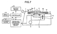
- an inverted microscope apparatus illustrated in FIG. 7 can be exemplified as Modified Example 2 of the first embodiment.
- Modified Example 2 is different from the first embodiment in that an inverted microscope apparatus according to Modified Example 2 includes a storage device 17 which stores a command of selection of the objective lens 4 by the input device 15.
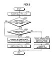
- FIG. 8 is a flowchart of a switching operation between the objective lenses 4 according to Modified Example 2 of the first embodiment of the present invention.
- Step S301 if the objective lens 4 is selected using the input device 15 (Step S301), the controller 8 determines whether or not the switching restriction of the objective lens 4 is valid (Step S302). If the switching restriction of the objective lens 4 is not valid (No in Step S302), the controller 8 transmits the information on the selection of the objective lens 4 (Step S303), and the revolver operation control device 7 switches the objective lens 4 (Step S304).
- Step S305 determines whether or not the microswitch 13 is pressed.
- the controller 8 transmits the acquired information on the selection of the objective lens 4 (Step S303), and the revolver operation control device 7 receives the information on the selection of the objective lens and switches to the objective lens 4 (Step S304).
- Step S305 If the microswitch 13 is not pressed (No in Step S305), the information on the selection of the objective lens 4 in Step S301 is stored in the storage device 17 (Step S306), and an interrupting process is validated (Step S307).
- Step S307 The interrupting process in Step S307 is illustrated in FIG. 9 .
- the controller 8 determines whether or not the microswitch 13 is pressed (Step S401). When the microswitch 13 is pressed (Yes in Step S401), the controller 8 reads the information on the selection of the objective lens from the storage device 17 (Step S402) and transmits the read information on the selection of the objective lens to the revolver operation control device 7 (Step S403).
- the revolver operation control device 7 receives the information on the selection of the objective lens, switches to the objective lens 4 (Step S404).
- the interrupting process is invalidated (Step S405).
- Step S401 If the microswitch 13 is not pressed (No in Step S401), the interrupting process is ended.
- the information on the selection of the objective lens 4 stored in the storage device 17 may be the information on the selection of the objective lens 4 which is first selected. If the storage device 17 can store a plurality of information items on the selection of the objective lens, the information on the selection of the objective lens 4 which is finally selected may be transmitted.
- FIG. 10 is a schematic diagram illustrating a configuration of an inverted microscope apparatus according to the second embodiment of the present invention.
- the stage according to the second embodiment of the present invention is an electric stage 3A.
- the electric stage 3A is connected to a controller 8 through a stage operation control device 18.
- the objective lens 4 inserted under the specimen 2 becomes to be contacted with the electric stage 3A depending on positions of the electric revolver 5 and the electric stage 3A.
- the microswitch 13 determines that the electric stage 3A is in an operable state when the objective lens 4 and the electric stage 3A are separated from each other by a specified interval or more, and determines that the electric stage 3A is in an inoperable state when the objective lens 4 and the electric stage 3A are separated from each other by less than the specified interval. If the microswitch 13 is not pressed, that is, if the electric stage 3A is in the inoperable state, the controller 8 restricts transmission of a command of returning the electric stage 3A to the origin. In addition, besides the microswitch 13, a photo-interrupter, a capacitive sensor, or the like may be used as a state determining device of the second embodiment. In addition, the restriction of the returning of the electric stage 3A to the origin by the controller 8 may be selectively lifted. Therefore, user's convenience can be improved.
- FIG. 11 is a flowchart of the operation of returning the electric stage to the origin in the second embodiment of the present invention.
- Step S501 when returning of the electric stage 3A to the origin is commanded by the user, the input device 15 is operated (Step S501).
- Step S501 the controller 8 determines whether or not the returning of the electric stage 3A to the origin restriction is valid (Step S502). If the returning of the electric stage 3A to the origin restriction is not valid (No in Step S502), the controller 8 transmits information on the command of returning the electric stage 3A to the origin commanded in Step S501 to the stage operation control device 18 (Step S503), and the stage operation control device 18 receives the information on the command of returning to the origin and returns the electric stage 3A to the origin (Step S504).
- Step S505 the controller 8 determines whether or not the microswitch 13 is pressed.
- Step S505 If the microswitch 13 is not pressed (No in Step S505), the objective lens 4 inserted under the specimen 2 and the electric stage 3A are separated from each other by less than a specified interval. If the electric stage 3A is returned to the origin in this state, the objective lens 4 becomes to be contacted with the electric stage 3A. Therefore, it is determined that the electric stage 3A is in the inoperable state, so that the controller 8 ends the operation of returning the electric stage 3A to the origin.
- Step S505 When the microswitch 13 is pressed (Yes in Step S505), the objective lens 4 inserted under the specimen 2 and the electric stage 3A are separated from each other by the specified interval or more, and it is determined that the electric stage 3A is in the operable state. Therefore, the controller 8 transmits information on the returning of the electric stage 3A to the origin (Step S503), and the stage operation control device 18 receives the information on the returning to the origin and returns the electric stage 3A to the origin (Step S504).
- the controller 8 may function as a restriction device
- the stage operation control device 18 may also function as a restriction device.
- the inverted microscope apparatus illustrated in FIG. 10 includes the electric revolver 5 and the revolver operation control device 7, the manual revolver 5A may be used if it has a state determining device.
- the inverted microscope apparatus is described as an example, the same description can be applied to an upright microscope apparatus.
- the operable and inoperable states of the electric stage 3A can be determined by the microswitch 13, it is possible to prevent the contact of the objective lens 4 with the electric stage 3A during the operation of returning the electric stage 3A to the origin by using a simple configuration without performing a process of acquiring information on the position of the objective lens 4.
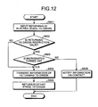
- FIG. 12 is a flowchart of an operation of returning the electric stage to the origin according to Modified Example 1 of the second embodiment of the present invention.
- Steps S601 to S604 are the same as Steps S501 to S504 of the second embodiment, respectively. If the returning to the origin restriction is valid (Yes in Step S602), the controller 8 determines whether or not the microswitch 13 is pressed (Step S605). If the microswitch 13 is not pressed (No in Step S605), the output device 16 is allowed to notify a possibility of the contact of the objective lens 4 with the electric stage 3A (Step S606).
- Step S603 When the microswitch 13 is pressed (Yes in Step 5605), the controller 8 transmits the information on the returning to the origin (Step S603), and the stage operation control device 18 receives the information on the returning to the origin and returns the electric stage to the origin (Step S604).
- an inverted microscope apparatus illustrated in FIG. 13 may be exemplified as Modified Example 2 of the second embodiment.
- Modified Example 2 is different from the second embodiment in that the inverted microscope apparatus according to Modified Example 2 includes a storage device 17 which stores the information on the returning of the electric stage 3A to the origin which is input by the input device 15.
- the position thereof in the height direction is the position where the objective lens 4 does not contact with the stage 3 during the driving of the electric revolver 5 by taking into consideration the objective lens 4 attachable to the electric revolver 5 and the stage 3 attachable to the inverted microscope apparatus.
- the driving of the electric revolver 5 can be performed. In the state where the microswitch 13 is not pressed, since the objective lens 4 becomes to be contacted with the stage 3, the driving of the electric revolver 5 is restricted.
- a photo-interrupter, a capacitive sensor, or the like may be used as a state determining device of the third embodiment.
- the output device 16 is allowed to notify a possibility of the contact of the objective lens 4 with the stage 3, and the user lifts down the electric revolver 5. Therefore, as illustrated in FIG. 15 , the microswitch 13 is pressed by the protrusion 14, so that the controller 8 lifts the restriction of the transmission of the information on the selection of the objective lens 4 to the revolver operation control device 7.
- the storage device 17 may store the command of selection of the objective lens 4, so that when the information on the selection of the objective lens 4 is input under the condition that the microswitch 13 is not switched to a state where the electric revolver 5 is in an operable state (i.e., the microswitch 13 is in a switch-off state), the information on the selection is stored in the storage device 17, and when the microswitch 13 is pressed, the information in the storage device 17 is acquired to identify the objective lens 4.
- the microswitch 13 arranged on the rear side surface of the electric revolver 5 since it is determined whether the switching operation between the objective lenses 4 is possible or not, by using the microswitch 13 arranged on the rear side surface of the electric revolver 5, it is possible to prevent the contact of the objective lens 4 with the stage 3 during the switching operation between the objective lenses 4, with a simple configuration, without performing complicated processes such as tracing the rotation trajectory of the objective lens 4.
- the embodiment may be applied to the restriction of the command of returning the electric stage 3A to the origin.
Landscapes
- Physics & Mathematics (AREA)
- Chemical & Material Sciences (AREA)
- Analytical Chemistry (AREA)
- General Physics & Mathematics (AREA)
- Optics & Photonics (AREA)
- Microscoopes, Condenser (AREA)
Abstract
Description
- The present invention relates to a microscope apparatus.
- Microscope apparatuses capable of observing a magnified image of a fine specimen and recording the observation image as a picture or a video image have been used in a wide variety of fields such as biological fields or industrial fields. In the industrial fields, for example, the microscope apparatuses have been used for observing microstructures of a metal or used as an inspection apparatus in a process of manufacturing a semiconductor device or an LCD (liquid crystal display).
- Since the microscope apparatus is used for the above-described various fields, in many cases, components thereof are configured as units, so that the microscope apparatus may be used in various uses according to a combination of the units.
- Among the units, there are movable units which are electrically operated, such as an electric stage. Besides the electric stage, there are many units including the electric movable device. However, there are still a lot of units including a manual movable device.
- In the microscope apparatus, in some cases, if the movable device is manipulated carelessly, the movable device becomes to be contacted with other device. Although the electric movable device can be operated by simple manipulation, even in the state where contact may occur if there is no method of preventing the contact, the electric movable device performs the associated operation as it is. Particularly, in an inverted microscope, since the objective lens is inserted into an aperture of the stage, it is difficult for a user to determine the occurrence of contact. If switching of the electric revolver is manipulated carelessly, the objective lens becomes to be contacted with the specimen or the stage, so that the specimen or the objective lens may be destructed.
- In order to solve this problem, there is disclosed a technique for a safe observation, which can be performed by rotating an electric revolver after recessing the position of a focusing device or a stage in the case of an objective lens becomes to be contacted with the stage. In this case, the contact can be decided by the information of the position of the focusing device and the stage obtained by tracing a rotation trajectory of the objective lens. (refer to, for example, Japanese Laid-open Patent Publication No.
2007-286440 - However, since the information on the positions of the focusing device and the stage needs to be acquired, the configuration of acquiring the information on the positions is needed. In addition, since the rotation trajectory of the objective lens needs to be calculated every time of manipulation, the control becomes complicated.
- In view of the foregoing, an object of the present invention is to provide a microscope apparatus capable of preventing contact of an electric movable device with the other devices when the electric movable device is operated, with a simple configuration and control.
- In some embodiments, a microscope apparatus includes a stage on which a specimen is mounted, a revolver that holds a plurality of objective lenses and is configured to cause one of the plurality of objective lenses to be arranged on an observation light axis by a revolving motion. At least one of the stage and the revolver constitutes an electric movable device that is electrically operated. The microscope apparatus further includes an input device configured to input a command for operating the electric movable device; a manual focusing device configured to adjust a relative distance between the stage and the objective lenses; an operation control device configured to control operation of the electric movable device; a state determining device configured to determine that the electric movable device is in an operable state when the objective lenses and the stage are separated by a specified interval or more and to determine that the electric movable device is in an inoperable state when the objective lenses and the stage are separated by less than the specified interval; and a restriction device configured to restrict an output of a control signal for commanding the operation to the operation control device when the command for operating the electric movable device is input by the input device if the state determining device determines that the electric movable device is in the inoperable state.
- The above and other features, advantages and technical and industrial significance of this invention will be better understood by reading the following detailed description of presently preferred embodiments of the invention, when considered in connection with the accompanying drawings.
-
-
FIG. 1 is a schematic diagram illustrating a configuration of an inverted microscope apparatus according to a first embodiment of the present invention; -
FIG. 2 is a diagram illustrating switching between revolvers in the inverted microscope apparatus illustrated inFIG. 1 ; -
FIG. 3 is a flowchart of a switching operation between objective lenses according to the first embodiment of the present invention; -
FIG. 4 is a diagram illustrating contact of an objective lens with a stage in the inverted microscope apparatus illustrated inFIG. 1 ; -
FIG. 5 is a diagram illustrating the contact of the objective lens with the stage in the inverted microscope apparatus illustrated inFIG. 1 ; -
FIG. 6 is a flowchart of a switching operation between the objective lenses according to Modified Example 1 of the first embodiment of the present invention; -
FIG. 7 is a schematic diagram illustrating a configuration of an inverted microscope apparatus according to Modified Example 2 of the first embodiment of the present invention; -
FIG. 8 is a flowchart of a switching operation between the objective lenses according to Modified Example 2 of the first embodiment of the present invention; -
FIG. 9 is a flowchart of an interrupting process illustrated inFIG. 8 ; -
FIG. 10 is a schematic diagram illustrating a configuration of an inverted microscope apparatus according to a second embodiment of the present invention; -
FIG. 11 is a flowchart of an operation of returning an electric stage to an origin according to the second embodiment of the present invention; -
FIG. 12 is a flowchart of an operation of returning an electric stage to an origin according to Modified Example 1 of the second embodiment of the present invention; -
FIG. 13 is a schematic diagram illustrating a configuration of an inverted microscope apparatus according to Modified Example 2 of the second embodiment of the present invention; -
FIG. 14 is a schematic partial cross-sectional diagram illustrating a configuration of an inverted microscope apparatus according to a third embodiment of the present invention; -
FIG. 15 is a partial cross-sectional diagram illustrating a switching state of a switch of the inverted microscope apparatus illustrated inFIG. 14 ; and -
FIG. 16 is a schematic partial cross-sectional diagram illustrating a configuration of an inverted microscope apparatus according to a modified example of the third embodiment of the present invention. - Exemplary embodiments will be described with reference to the accompanying drawings. The present invention is not limited to the embodiments, but various changes thereof may be available without departing from the scope of the invention.
-
FIG. 1 is a schematic diagram of a configuration of an inverted microscope apparatus according to a first embodiment of the present invention. The inverted microscope apparatus includes a microscopemain body 1, astage 3 on which aspecimen 2 is mounted, anelectric revolver 5 which holds a plurality ofobjective lenses 4 and which is configured to electrically cause selected one of theobjective lenses 4 to be arranged on an observation light axis, and amanual focusing device 6 which supports theelectric revolver 5 and which is configured to adjust a distance between the specimen 2 (stage 3) and theobjective lens 4. - The
electric revolver 5 is fixed to the manual focusingdevice 6 by fastener members (not illustrated) such as bolts. A user rotates a focusinghandle 9 to lift up and down the manual focusingdevice 6 so that the distance between thespecimen 2 and theobjective lens 4 can be adjusted. Theelectric revolver 5 is replaceable with amanual revolver 5A as illustrated inFIG. 2 . That is, theelectric revolver 5 and themanual revolver 5A can be replaced with one another by a user depending on an observation method. In addition, even if other inverted microscope apparatus is employed in which theelectric revolver 5 is mounted in a non-removable manner, it is also considered to be "replaced" at the case in which the manual focusingdevice 6 is provided and themanual revolver 5A is attachable to it. - The
stage 3 is fixed to the microscopemain body 1 by fastener members (not illustrated) such as bolts. Thestage 3 is configured to include alower plate 10, amiddle plate 11, and anupper plate 12. Thelower plate 10, themiddle plate 11, and theupper plate 12 haverespective apertures objective lens 4 is inserted into theapertures objective lens 4 and thespecimen 2 is adjusted. Thestage 3 according to the first embodiment may be used in a manual or electric manner. If the sizes of stages having different sizes are within a specified range, any one of the stages can be used as thestage 3 attached in the microscopemain body 1. - The
electric revolver 5 is configured to include amicroswitch 13 as a state determining device. Themicroswitch 13 is a mechanical switch and is arranged on the bottom surface of theelectric revolver 5. Aprotrusion 14 is installed in the microscopemain body 1 at the position facing themicroswitch 13. If the manual focusingdevice 6 is lifted down by rotation of thefocusing handle 9, themicroswitch 13 is pressed by theprotrusion 14. Alternatively, theprotrusion 14 may be removed, and themicroswitch 13 may be configured to be in a protruded shape. Furthermore, themicroswitch 13 may be formed in a protruded shape in the microscopemain body 1, and themicroswitch 13 may be configured to be pressed by lifting down theelectric revolver 5. In addition, besides themicroswitch 13, a photo-interrupter, a capacitive sensor, or the like may be used as the state determining device. - A revolver operation control device 7 controls operations of the
electric revolver 5. If the user selects theobjective lens 4 held by theelectric revolver 5 through a below-describedinput device 15, the revolver operation control device 7 controls the operations of theelectric revolver 5 so that the selectedobjective lens 4 is inserted under thespecimen 2. The revolver operation control device 7 may be built in theelectric revolver 5 or be formed integrally with a below-describedcontroller 8. - The
controller 8 is connected to the revolver operation control device 7, theinput device 15, and anoutput device 16. In the first embodiment, thecontroller 8 functions as a restriction device. If themicroswitch 13 is not pressed, even when theobjective lens 4 is selected by a below-describedinput device 15, thecontroller 8 restricts transmission of information on the selection of theobjective lens 4 to the revolver operation control device 7. A PC may be used as thecontroller 8. In addition, the restriction of the switching between theobjective lenses 4 in the revolver operation control device 7 by thecontroller 8 may be selectively lifted. Therefore, user's convenience can be improved. - The
input device 15 is configured to input a command for selecting one of theobjective lenses 4 held by theelectric revolver 5. The selective input may be performed, for example, by a mechanical switch, a touch panel, or the like. In the first embodiment, the selective input may be made for selecting an objective lens directly or for commanding some divisions of rotation from a current position of the objective lens to the right or left position. - The
output device 16 outputs the type of the selectedobjective lens 4 or the hole number of theelectric revolver 5 and outputs the signal whether or not theobjective lens 4 selected by theinput device 15 contacts with thestage 3. For example, an LED or a display may be used as theoutput device 16. In the case of outputting the existence or non-existence of contact, a buzzer may be used as theoutput device 16. In addition, a plurality of LEDs or buzzers may be used as theoutput device 16. - Next, an operation of switching the
objective lens 4 in the inverted microscope apparatus according to the first embodiment of the present invention will be described with reference to the drawings.FIG. 3 is a flowchart of a switching operation between theobjective lenses 4 according to the first embodiment of the present invention.FIGS. 4 and 5 are diagrams illustrating the contact of theobjective lens 4 with thestage 3 in the inverted microscope apparatus illustrated inFIG. 1 . - As illustrated in
FIG. 3 , when the user switches to theobjective lens 4 for observation of thespecimen 2, theobjective lens 4 is selected using the input device 15 (Step S101). - After the
objective lens 4 is selected in Step S101, thecontroller 8 determines whether or not the switching restriction of theobjective lenses 4 is valid (Step S102). If the switching restriction of theobjective lens 4 is not valid (No in Step S102), thecontroller 8 transmits the information on the selection of theobjective lens 4 selected in Step S101 to the revolver operation control device 7 (Step S103), and the revolver operation control device 7 receives the information on the selection of the objective lens and controls theelectric revolver 5 to insert the selectedobjective lens 4 under thespecimen 2 to switch to the objective lens 4 (Step S104). - If the switching restriction of the
objective lens 4 is valid (Yes in Step S102), thecontroller 8 determines whether or not themicroswitch 13 is pressed (Step S105). - If the
microswitch 13 is not pressed (No in Step S105), theobjective lens 4 inserted under thespecimen 2 and thestage 3 are separated from each other by less than a specified interval. If theelectric revolver 5 is operated in this state, theobjective lens 4 becomes to be contacted with thestage 3 due to arotation trajectory 20 of theobjective lens 4 indicated by a dotted line illustrated inFIG. 4 . Therefore, it is determined that theelectric revolver 5 is in an inoperable state, so that thecontroller 8 ends the operation of switching between theobjective lenses 4. - When the
microswitch 13 is pressed (Yes in Step S105), theobjective lens 4 inserted under thespecimen 2 and thestage 3 are separated from each other by the specified interval or more. Therefore, it is determined that theelectric revolver 5 is in an operable state, and thecontroller 8 transmits the information on the selection of the objective lens 4 (Step S103), and the revolver operation control device 7 receives the information on the selection of the objective lens and switches to the objective lens 4 (Step S104). - In the first embodiment, although the
controller 8 functions as a restriction device, the revolver operation control device 7 may also function as a restriction device. - In the first embodiment, since the operable and inoperable states of the
electric revolver 5 can be determined by themicroswitch 13, it is possible to prevent the contact of theobjective lens 4 with thestage 3 during the switching between theobjective lenses 4, with a simple configuration, without performing complicated processes such as calculation of the rotation trajectory of theobjective lens 4. - In addition, in the first embodiment, since the
electric revolver 5 and themanual revolver 5A are replaceable with each other, in an inverted microscope apparatus having themanual revolver 5A, themanual revolver 5A can be replaced with theelectric revolver 5. Therefore, a part of a manual microscope can be upgraded to have an electric configuration. In addition, this configuration is suitable for appropriately replacing between theelectric revolver 5 and themanual revolver 5A. - Although the inverted microscope apparatus is described as an example in the first embodiment, the first embodiment may be applied to an upright microscope apparatus. In the inverted microscope apparatus, since the moving range of the manual focusing
device 6 is narrow, even if the determination of the operable state and inoperable state of the electric movable device by themicroswitch 13 is made at the lowermost limit of the movable range of the manual focusingdevice 6, there is no need to increase the moving amount of the manual focusingdevice 6, and it is possible to appropriately shorten the time required for switching between theobjective lenses 4. - In addition, in the first embodiment, if the
microswitch 13 is not pressed, the contact of theobjective lens 4 with thestage 3 may be notified by theoutput device 16.FIG. 6 is a flowchart of a switching operation between theobjective lenses 4 according to Modified Example 1 of the first embodiment of the present invention. - In Modified Example 1, Steps S201 to S204 are the same as Steps S101 to S104 of the first embodiment. If the switching restriction of the
objective lens 4 is valid (Yes in Step S202), thecontroller 8 determines whether or not themicroswitch 13 is pressed (Step S205). If themicroswitch 13 is not pressed (No in Step S205), theoutput device 16 is allowed to notify the contact of theobjective lens 4 with the stage 3 (Step S206). - When the
microswitch 13 is pressed (Yes in Step S205), thecontroller 8 transmits the information on the selection of the objective lens 4 (Step S203), and the revolver operation control device 7 receives the information on the selection of the objective lens and switches to the objective lens 4 (step S204). - In addition, an inverted microscope apparatus illustrated in
FIG. 7 can be exemplified as Modified Example 2 of the first embodiment. Modified Example 2 is different from the first embodiment in that an inverted microscope apparatus according to Modified Example 2 includes astorage device 17 which stores a command of selection of theobjective lens 4 by theinput device 15. - A switching operation between the
objective lenses 4 according to Modified Example of the first embodiment of the present invention will be described with reference to the drawings.FIG. 8 is a flowchart of a switching operation between theobjective lenses 4 according to Modified Example 2 of the first embodiment of the present invention. - As illustrated in
FIG. 8 , if theobjective lens 4 is selected using the input device 15 (Step S301), thecontroller 8 determines whether or not the switching restriction of theobjective lens 4 is valid (Step S302). If the switching restriction of theobjective lens 4 is not valid (No in Step S302), thecontroller 8 transmits the information on the selection of the objective lens 4 (Step S303), and the revolver operation control device 7 switches the objective lens 4 (Step S304). - If the switching restriction of the
objective lens 4 is valid (Yes in Step S302), thecontroller 8 determines whether or not themicroswitch 13 is pressed (Step S305). When themicroswitch 13 is pressed (Yes in Step S305), thecontroller 8 transmits the acquired information on the selection of the objective lens 4 (Step S303), and the revolver operation control device 7 receives the information on the selection of the objective lens and switches to the objective lens 4 (Step S304). - If the
microswitch 13 is not pressed (No in Step S305), the information on the selection of theobjective lens 4 in Step S301 is stored in the storage device 17 (Step S306), and an interrupting process is validated (Step S307). - The interrupting process in Step S307 is illustrated in
FIG. 9 . Thecontroller 8 determines whether or not themicroswitch 13 is pressed (Step S401). When themicroswitch 13 is pressed (Yes in Step S401), thecontroller 8 reads the information on the selection of the objective lens from the storage device 17 (Step S402) and transmits the read information on the selection of the objective lens to the revolver operation control device 7 (Step S403). The revolver operation control device 7 receives the information on the selection of the objective lens, switches to the objective lens 4 (Step S404). The interrupting process is invalidated (Step S405). - If the
microswitch 13 is not pressed (No in Step S401), the interrupting process is ended. - In Modified Example 2 of the first embodiment, even when the transmission of the information on the selection of the
objective lens 4 is restricted, there is no need to select theobjective lens 4 again, and it is possible to further shorten the time required for switching between theobjective lenses 4. In addition, if the information on the selection of theobjective lens 4 is input several times, the information on the selection of theobjective lens 4 stored in thestorage device 17 may be the information on the selection of theobjective lens 4 which is first selected. If thestorage device 17 can store a plurality of information items on the selection of the objective lens, the information on the selection of theobjective lens 4 which is finally selected may be transmitted. -
FIG. 10 is a schematic diagram illustrating a configuration of an inverted microscope apparatus according to the second embodiment of the present invention. The stage according to the second embodiment of the present invention is anelectric stage 3A. Theelectric stage 3A is connected to acontroller 8 through a stageoperation control device 18. - If a user inputs an operation of returning to the origin through the
input device 15, theobjective lens 4 inserted under thespecimen 2 becomes to be contacted with theelectric stage 3A depending on positions of theelectric revolver 5 and theelectric stage 3A. - Therefore, in the second embodiment, the
microswitch 13 determines that theelectric stage 3A is in an operable state when theobjective lens 4 and theelectric stage 3A are separated from each other by a specified interval or more, and determines that theelectric stage 3A is in an inoperable state when theobjective lens 4 and theelectric stage 3A are separated from each other by less than the specified interval. If themicroswitch 13 is not pressed, that is, if theelectric stage 3A is in the inoperable state, thecontroller 8 restricts transmission of a command of returning theelectric stage 3A to the origin. In addition, besides themicroswitch 13, a photo-interrupter, a capacitive sensor, or the like may be used as a state determining device of the second embodiment. In addition, the restriction of the returning of theelectric stage 3A to the origin by thecontroller 8 may be selectively lifted. Therefore, user's convenience can be improved. - An operation of returning the electric stage to the origin in the inverted microscope apparatus according to the second embodiment of the present invention will be described with reference to the drawings.
FIG. 11 is a flowchart of the operation of returning the electric stage to the origin in the second embodiment of the present invention. - As illustrated in
FIG. 11 , when returning of theelectric stage 3A to the origin is commanded by the user, theinput device 15 is operated (Step S501). - After the returning of the
electric stage 3A to the origin is commanded in Step S501, thecontroller 8 determines whether or not the returning of theelectric stage 3A to the origin restriction is valid (Step S502). If the returning of theelectric stage 3A to the origin restriction is not valid (No in Step S502), thecontroller 8 transmits information on the command of returning theelectric stage 3A to the origin commanded in Step S501 to the stage operation control device 18 (Step S503), and the stageoperation control device 18 receives the information on the command of returning to the origin and returns theelectric stage 3A to the origin (Step S504). - If the returning of the
electric stage 3A to the origin restriction is valid (Yes in Step S502), thecontroller 8 determines whether or not themicroswitch 13 is pressed (Step S505). - If the
microswitch 13 is not pressed (No in Step S505), theobjective lens 4 inserted under thespecimen 2 and theelectric stage 3A are separated from each other by less than a specified interval. If theelectric stage 3A is returned to the origin in this state, theobjective lens 4 becomes to be contacted with theelectric stage 3A. Therefore, it is determined that theelectric stage 3A is in the inoperable state, so that thecontroller 8 ends the operation of returning theelectric stage 3A to the origin. - When the
microswitch 13 is pressed (Yes in Step S505), theobjective lens 4 inserted under thespecimen 2 and theelectric stage 3A are separated from each other by the specified interval or more, and it is determined that theelectric stage 3A is in the operable state. Therefore, thecontroller 8 transmits information on the returning of theelectric stage 3A to the origin (Step S503), and the stageoperation control device 18 receives the information on the returning to the origin and returns theelectric stage 3A to the origin (Step S504). - In the second embodiment, although the
controller 8 may function as a restriction device, the stageoperation control device 18 may also function as a restriction device. In addition, although the inverted microscope apparatus illustrated inFIG. 10 includes theelectric revolver 5 and the revolver operation control device 7, themanual revolver 5A may be used if it has a state determining device. In addition, in the second embodiment, although the inverted microscope apparatus is described as an example, the same description can be applied to an upright microscope apparatus. - In the second embodiment, since the operable and inoperable states of the
electric stage 3A can be determined by themicroswitch 13, it is possible to prevent the contact of theobjective lens 4 with theelectric stage 3A during the operation of returning theelectric stage 3A to the origin by using a simple configuration without performing a process of acquiring information on the position of theobjective lens 4. - In addition, in the second embodiment, if the
microswitch 13 is not pressed, theoutput device 16 may be allowed to notify the contact of theobjective lens 4 with theelectric stage 3A.FIG. 12 is a flowchart of an operation of returning the electric stage to the origin according to Modified Example 1 of the second embodiment of the present invention. - In Modified Example 1, Steps S601 to S604 are the same as Steps S501 to S504 of the second embodiment, respectively. If the returning to the origin restriction is valid (Yes in Step S602), the
controller 8 determines whether or not themicroswitch 13 is pressed (Step S605). If themicroswitch 13 is not pressed (No in Step S605), theoutput device 16 is allowed to notify a possibility of the contact of theobjective lens 4 with theelectric stage 3A (Step S606). - When the
microswitch 13 is pressed (Yes in Step 5605), thecontroller 8 transmits the information on the returning to the origin (Step S603), and the stageoperation control device 18 receives the information on the returning to the origin and returns the electric stage to the origin (Step S604). - In addition, an inverted microscope apparatus illustrated in
FIG. 13 may be exemplified as Modified Example 2 of the second embodiment. Modified Example 2 is different from the second embodiment in that the inverted microscope apparatus according to Modified Example 2 includes astorage device 17 which stores the information on the returning of theelectric stage 3A to the origin which is input by theinput device 15. - In Modified Example 2 of the second embodiment, even when the transmission of information on the returning of the
electric stage 3A to the origin is restricted, there is no need to input the returning to the origin again, and it is possible to further shorten the time required for the operation of returning theelectric stage 3A to the origin. -
FIG. 14 is a schematic partial enlarged diagram illustrating a configuration of an inverted microscope apparatus according to a third embodiment of the present invention. The third embodiment of the present invention is different from the first embodiment in that the inverted microscope apparatus according to the third embodiment is configured so that themicroswitch 13 is arranged on the rear side surface of theelectric revolver 5. In addition, theprotrusion 14 is arranged on the rear side surface of the microscopemain body 1. The position of theprotrusion 14 in the lateral direction is the position where theprotrusion 14 is in contact with themicroswitch 13 when theelectric revolver 5 is moved up and down. The position thereof in the height direction is the position where theobjective lens 4 does not contact with thestage 3 during the driving of theelectric revolver 5 by taking into consideration theobjective lens 4 attachable to theelectric revolver 5 and thestage 3 attachable to the inverted microscope apparatus. In the third embodiment, if the manual focusingdevice 6 is lifted down and themicroswitch 13 is pressed by theprotrusion 14, the driving of theelectric revolver 5 can be performed. In the state where themicroswitch 13 is not pressed, since theobjective lens 4 becomes to be contacted with thestage 3, the driving of theelectric revolver 5 is restricted. Besides themicroswitch 13, a photo-interrupter, a capacitive sensor, or the like may be used as a state determining device of the third embodiment. - As illustrated in
FIG. 14 , if themicroswitch 13 is not pressed, theobjective lens 4 becomes to be contacted with thestage 3 as illustrated in therotation trajectory 20 of theobjective lens 4 inFIG. 14 . Therefore, even when the information on the selection of theobjective lens 4 is input through theinput device 15, thecontroller 8 restricts the transmission of the information on the selection of theobjective lens 4 to the revolver operation control device 7. - The
output device 16 is allowed to notify a possibility of the contact of theobjective lens 4 with thestage 3, and the user lifts down theelectric revolver 5. Therefore, as illustrated inFIG. 15 , themicroswitch 13 is pressed by theprotrusion 14, so that thecontroller 8 lifts the restriction of the transmission of the information on the selection of theobjective lens 4 to the revolver operation control device 7. - In the third embodiment, although the
controller 8 functions as a restriction device, the revolver operation control device 7 may also function as a restriction device. In addition, for user's convenience, the restriction of the transmission of the information on the selection of theobjective lens 4 may be selectively lifted. In addition, in the third embodiment, although the inverted microscope apparatus is described as an example, the same description can be applied to an upright microscope apparatus. Further, as illustrated inFIG. 16 , the height of theprotrusion 14 may be adjusted, so that the position where themicroswitch 13 is pressed, that is, the relative distance for preventing the contact of theobjective lens 4 with thestage 3 can be adjusted. In addition, thestorage device 17 may store the command of selection of theobjective lens 4, so that when the information on the selection of theobjective lens 4 is input under the condition that themicroswitch 13 is not switched to a state where theelectric revolver 5 is in an operable state (i.e., themicroswitch 13 is in a switch-off state), the information on the selection is stored in thestorage device 17, and when themicroswitch 13 is pressed, the information in thestorage device 17 is acquired to identify theobjective lens 4. - According to the third embodiment, since it is determined whether the switching operation between the
objective lenses 4 is possible or not, by using themicroswitch 13 arranged on the rear side surface of theelectric revolver 5, it is possible to prevent the contact of theobjective lens 4 with thestage 3 during the switching operation between theobjective lenses 4, with a simple configuration, without performing complicated processes such as tracing the rotation trajectory of theobjective lens 4. - In addition, as Modified Example of the third embodiment, if the
electric stage 3A is provided, the embodiment may be applied to the restriction of the command of returning theelectric stage 3A to the origin. - Additional advantages and modifications will readily occur to those skilled in the art. Therefore, the invention in its broader aspects is not limited to the specific details and representative embodiments shown and described herein.
Claims (7)
- A microscope apparatus comprising:a stage (3, 3A) on which a specimen is mounted;a revolver (5, 5A) that holds a plurality of objective lenses (4) and is configured to cause one of the plurality of objective lenses (4) to be arranged on an observation light axis by a revolving motion, at least one of the stage (3, 3A) and the revolver (5, 5A) constituting an electric movable device (3A, 5) that is electrically operated;an input device (15) configured to input a command for operating the electric movable device (3A, 5);a manual focusing device (6) configured to adjust a relative distance between the stage (3, 3A) and the objective lenses (4);an operation control device (7, 18) configured to control operation of the electric movable device (3A, 5);a state determining device (13) configured to determine that the electric movable device (3A, 5) is in an operable state when the objective lenses (4) and the stage (3, 3A) are separated by a specified interval or more and to determine that the electric movable device (3A, 5) is in an inoperable state when the objective lenses (4) and the stage (3, 3A) are separated by less than the specified interval; anda restriction device (8) configured to restrict an output of a control signal for commanding the operation to the operation control device (7, 18) when the command for operating the electric movable device (3A, 5) is input by the input device (15) if the state determining device (13) determines that the electric movable device (3A, 5) is in the inoperable state.
- The microscope apparatus according to claim 1,
wherein the electric movable device (3A, 5) is the revolver (5) configured to revolve electrically, and
the revolver (5) is replaceable and attached to the manual focusing device (6). - The microscope apparatus according to claim 1 or 2, wherein the state determining device (13) is mounted on the revolver (5, 5A).
- The microscope apparatus according to any one of claims 1 to 3, wherein the restriction device (8) is configured to selectively lift the restriction on the output of the control signal to the operation control device (7, 18).
- The microscope apparatus according to any one of claims 1 to 3, further comprising a storage device (17) that stores the command for operating the electric movable device (3A, 5) input by the input device (15),
wherein the storage device (17) stores the command when the restriction device (8) restricts the output of the control signal to the operation control device (7, 18), and
after the restriction on the output of the control signal is lifted, the restriction device (8) acquires the command from the storage device (17) and outputs the control signal to the operation control device (7, 18) based on the command. - The microscope apparatus according to any one of claims 1 to 5, wherein the microscope apparatus is an inverted microscope apparatus.
- The microscope apparatus according to any one of claims 1 to 6, wherein at a lower limit of a movable range by the manual focusing device (6), the state determining device (13) determines that the electric movable device (3A, 5) is in the operable state.
Applications Claiming Priority (1)
| Application Number | Priority Date | Filing Date | Title |
|---|---|---|---|
| JP2012103915A JP5969808B2 (en) | 2012-04-27 | 2012-04-27 | Microscope equipment |
Publications (2)
| Publication Number | Publication Date |
|---|---|
| EP2657749A1 true EP2657749A1 (en) | 2013-10-30 |
| EP2657749B1 EP2657749B1 (en) | 2017-12-13 |
Family
ID=48193075
Family Applications (1)
| Application Number | Title | Priority Date | Filing Date |
|---|---|---|---|
| EP13002197.5A Active EP2657749B1 (en) | 2012-04-27 | 2013-04-25 | Microscope apparatus |
Country Status (3)
| Country | Link |
|---|---|
| US (1) | US9557552B2 (en) |
| EP (1) | EP2657749B1 (en) |
| JP (1) | JP5969808B2 (en) |
Cited By (2)
| Publication number | Priority date | Publication date | Assignee | Title |
|---|---|---|---|---|
| WO2016012603A1 (en) * | 2014-07-24 | 2016-01-28 | Leica Microsystems Cms Gmbh | Microscope having covers for combined protection against jamming and against light |
| DE102017120651B3 (en) * | 2017-09-07 | 2018-11-08 | Leica Microsystems Cms Gmbh | Microscope with collision protection and corresponding procedure |
Families Citing this family (4)
| Publication number | Priority date | Publication date | Assignee | Title |
|---|---|---|---|---|
| TWI533025B (en) * | 2014-07-07 | 2016-05-11 | 億觀生物科技股份有限公司 | Portable microscope |
| JP2016102854A (en) * | 2014-11-27 | 2016-06-02 | オリンパス株式会社 | Microscope system |
| JP6879310B2 (en) * | 2016-10-14 | 2021-06-02 | 株式会社ニコン | Microscope device |
| TWI810565B (en) * | 2021-05-14 | 2023-08-01 | 國立清華大學 | Portable ring-type fluorescence optical system for observing microfluidic channel and operating method thereof |
Citations (7)
| Publication number | Priority date | Publication date | Assignee | Title |
|---|---|---|---|---|
| DE3410201A1 (en) * | 1983-03-22 | 1984-10-04 | Olympus Optical Co., Ltd., Tokio/Tokyo | MICROSCOPE |
| GB2153547A (en) * | 1983-12-09 | 1985-08-21 | Reichert Optische Werke Ag | Microscope having a motor-drive objective turret |
| EP0508076A1 (en) * | 1991-04-12 | 1992-10-14 | LEICA MIKROSKOPIE UND SYSTEME GmbH | Limit switch with preset overrun for the protection of the sample in microscopes with motorised focussing |
| US20040090670A1 (en) * | 2002-09-19 | 2004-05-13 | Olympus Optical Co., Ltd. | Microscope apparatus |
| JP2007286440A (en) | 2006-04-18 | 2007-11-01 | Olympus Corp | Inverted microscopic device |
| EP2180363A1 (en) * | 2008-10-27 | 2010-04-28 | Olympus Corporation | Microscope apparatus |
| EP2322967A1 (en) * | 2009-11-12 | 2011-05-18 | Olympus Corporation | Microscope system |
Family Cites Families (7)
| Publication number | Priority date | Publication date | Assignee | Title |
|---|---|---|---|---|
| JPS59172612A (en) * | 1983-03-22 | 1984-09-29 | Olympus Optical Co Ltd | Interlocking device between motor-driven revolver and motor-driven collimator of microscope |
| JPH03296707A (en) * | 1990-04-17 | 1991-12-27 | Olympus Optical Co Ltd | Microscope |
| JP3396070B2 (en) * | 1993-12-15 | 2003-04-14 | オリンパス光学工業株式会社 | Microscope equipment |
| JPH07333507A (en) * | 1994-06-07 | 1995-12-22 | Olympus Optical Co Ltd | Microscope system |
| JP3351115B2 (en) * | 1994-08-05 | 2002-11-25 | 株式会社ニコン | Rotating revolver control device for microscope |
| JP5121635B2 (en) * | 2008-08-28 | 2013-01-16 | オリンパス株式会社 | Microscope revolver |
| EP2246725A3 (en) * | 2009-04-30 | 2011-01-26 | Olympus Corporation | Microscope with fixed imaging unit and movable objective lens |
-
2012
- 2012-04-27 JP JP2012103915A patent/JP5969808B2/en active Active
-
2013
- 2013-04-25 EP EP13002197.5A patent/EP2657749B1/en active Active
- 2013-04-25 US US13/870,827 patent/US9557552B2/en active Active
Patent Citations (7)
| Publication number | Priority date | Publication date | Assignee | Title |
|---|---|---|---|---|
| DE3410201A1 (en) * | 1983-03-22 | 1984-10-04 | Olympus Optical Co., Ltd., Tokio/Tokyo | MICROSCOPE |
| GB2153547A (en) * | 1983-12-09 | 1985-08-21 | Reichert Optische Werke Ag | Microscope having a motor-drive objective turret |
| EP0508076A1 (en) * | 1991-04-12 | 1992-10-14 | LEICA MIKROSKOPIE UND SYSTEME GmbH | Limit switch with preset overrun for the protection of the sample in microscopes with motorised focussing |
| US20040090670A1 (en) * | 2002-09-19 | 2004-05-13 | Olympus Optical Co., Ltd. | Microscope apparatus |
| JP2007286440A (en) | 2006-04-18 | 2007-11-01 | Olympus Corp | Inverted microscopic device |
| EP2180363A1 (en) * | 2008-10-27 | 2010-04-28 | Olympus Corporation | Microscope apparatus |
| EP2322967A1 (en) * | 2009-11-12 | 2011-05-18 | Olympus Corporation | Microscope system |
Cited By (4)
| Publication number | Priority date | Publication date | Assignee | Title |
|---|---|---|---|---|
| WO2016012603A1 (en) * | 2014-07-24 | 2016-01-28 | Leica Microsystems Cms Gmbh | Microscope having covers for combined protection against jamming and against light |
| CN106537222A (en) * | 2014-07-24 | 2017-03-22 | 莱卡微系统Cms有限责任公司 | Microscope having covers for combined protection against jamming and against light |
| CN106537222B (en) * | 2014-07-24 | 2019-05-14 | 莱卡微系统Cms有限责任公司 | Microscope with cover for combined protection against pinch and light |
| DE102017120651B3 (en) * | 2017-09-07 | 2018-11-08 | Leica Microsystems Cms Gmbh | Microscope with collision protection and corresponding procedure |
Also Published As
| Publication number | Publication date |
|---|---|
| US20130286474A1 (en) | 2013-10-31 |
| JP2013231862A (en) | 2013-11-14 |
| EP2657749B1 (en) | 2017-12-13 |
| US9557552B2 (en) | 2017-01-31 |
| JP5969808B2 (en) | 2016-08-17 |
Similar Documents
| Publication | Publication Date | Title |
|---|---|---|
| EP2657749B1 (en) | Microscope apparatus | |
| US7732724B2 (en) | Detent changeover switch apparatus | |
| JP5468892B2 (en) | Microscope controller and microscope system including the microscope controller | |
| US10084896B1 (en) | Modular electronic devices | |
| CN1501217A (en) | Haptic Interface Device | |
| JP5661944B2 (en) | Apparatus and method for handling device programming | |
| KR20130073845A (en) | Display system, display apparatus, manipulation apparatus and function selection apparatus | |
| US10209817B1 (en) | Modular electronic devices | |
| EP2557446A1 (en) | Microscope controller and microscope system comprising the microscope controller | |
| US7262907B2 (en) | Microscope and method for operating a microscope | |
| US8873139B2 (en) | Microscope system and observation control method | |
| CN112227862B (en) | user interface unit | |
| US8649088B2 (en) | Microscope system | |
| JP5893313B2 (en) | Microscope system | |
| CN106133574B (en) | Operation microscope support | |
| JP2015095760A (en) | Microscope image display control method, microscope image display control program, and microscope image display device | |
| JP5649851B2 (en) | Microscope system having a microscope controller | |
| US8120576B2 (en) | Input display device, display control method and control program for allowing a cursor to shift to a selectable position | |
| CN118502096A (en) | Computer system for displaying sample image, microscope system and method for displaying sample image | |
| JP6701836B2 (en) | Character input device, character input method, and character input program | |
| EP4202524A1 (en) | Microscope control arrangement | |
| JP5965966B2 (en) | Microscope controller and microscope system having the microscope controller | |
| JP2024505842A (en) | handheld pipetting device | |
| JP4374893B2 (en) | Focusing device and microscope equipped with the same | |
| JP2016102854A (en) | Microscope system |
Legal Events
| Date | Code | Title | Description |
|---|---|---|---|
| PUAI | Public reference made under article 153(3) epc to a published international application that has entered the european phase |
Free format text: ORIGINAL CODE: 0009012 |
|
| AK | Designated contracting states |
Kind code of ref document: A1 Designated state(s): AL AT BE BG CH CY CZ DE DK EE ES FI FR GB GR HR HU IE IS IT LI LT LU LV MC MK MT NL NO PL PT RO RS SE SI SK SM TR |
|
| AX | Request for extension of the european patent |
Extension state: BA ME |
|
| 17P | Request for examination filed |
Effective date: 20140117 |
|
| RBV | Designated contracting states (corrected) |
Designated state(s): AL AT BE BG CH CY CZ DE DK EE ES FI FR GB GR HR HU IE IS IT LI LT LU LV MC MK MT NL NO PL PT RO RS SE SI SK SM TR |
|
| RAP1 | Party data changed (applicant data changed or rights of an application transferred) |
Owner name: OLYMPUS CORPORATION |
|
| RAP1 | Party data changed (applicant data changed or rights of an application transferred) |
Owner name: OLYMPUS CORPORATION |
|
| RAP1 | Party data changed (applicant data changed or rights of an application transferred) |
Owner name: OLYMPUS CORPORATION |
|
| RIN1 | Information on inventor provided before grant (corrected) |
Inventor name: KITAHARA, AKIHIRO Inventor name: TAKENAGA, SHOTA |
|
| STAA | Information on the status of an ep patent application or granted ep patent |
Free format text: STATUS: EXAMINATION IS IN PROGRESS |
|
| 17Q | First examination report despatched |
Effective date: 20170308 |
|
| GRAP | Despatch of communication of intention to grant a patent |
Free format text: ORIGINAL CODE: EPIDOSNIGR1 |
|
| STAA | Information on the status of an ep patent application or granted ep patent |
Free format text: STATUS: GRANT OF PATENT IS INTENDED |
|
| INTG | Intention to grant announced |
Effective date: 20170809 |
|
| RIN1 | Information on inventor provided before grant (corrected) |
Inventor name: TAKENAGA, SHOTA Inventor name: KITAHARA, AKIHIRO |
|
| GRAS | Grant fee paid |
Free format text: ORIGINAL CODE: EPIDOSNIGR3 |
|
| GRAA | (expected) grant |
Free format text: ORIGINAL CODE: 0009210 |
|
| STAA | Information on the status of an ep patent application or granted ep patent |
Free format text: STATUS: THE PATENT HAS BEEN GRANTED |
|
| AK | Designated contracting states |
Kind code of ref document: B1 Designated state(s): AL AT BE BG CH CY CZ DE DK EE ES FI FR GB GR HR HU IE IS IT LI LT LU LV MC MK MT NL NO PL PT RO RS SE SI SK SM TR |
|
| REG | Reference to a national code |
Ref country code: GB Ref legal event code: FG4D |
|
| REG | Reference to a national code |
Ref country code: AT Ref legal event code: REF Ref document number: 954936 Country of ref document: AT Kind code of ref document: T Effective date: 20171215 Ref country code: CH Ref legal event code: EP |
|
| REG | Reference to a national code |
Ref country code: IE Ref legal event code: FG4D |
|
| REG | Reference to a national code |
Ref country code: DE Ref legal event code: R096 Ref document number: 602013030657 Country of ref document: DE |
|
| REG | Reference to a national code |
Ref country code: NL Ref legal event code: MP Effective date: 20171213 |
|
| REG | Reference to a national code |
Ref country code: LT Ref legal event code: MG4D |
|
| PG25 | Lapsed in a contracting state [announced via postgrant information from national office to epo] |
Ref country code: LT Free format text: LAPSE BECAUSE OF FAILURE TO SUBMIT A TRANSLATION OF THE DESCRIPTION OR TO PAY THE FEE WITHIN THE PRESCRIBED TIME-LIMIT Effective date: 20171213 Ref country code: FI Free format text: LAPSE BECAUSE OF FAILURE TO SUBMIT A TRANSLATION OF THE DESCRIPTION OR TO PAY THE FEE WITHIN THE PRESCRIBED TIME-LIMIT Effective date: 20171213 Ref country code: SE Free format text: LAPSE BECAUSE OF FAILURE TO SUBMIT A TRANSLATION OF THE DESCRIPTION OR TO PAY THE FEE WITHIN THE PRESCRIBED TIME-LIMIT Effective date: 20171213 Ref country code: NO Free format text: LAPSE BECAUSE OF FAILURE TO SUBMIT A TRANSLATION OF THE DESCRIPTION OR TO PAY THE FEE WITHIN THE PRESCRIBED TIME-LIMIT Effective date: 20180313 |
|
| REG | Reference to a national code |
Ref country code: AT Ref legal event code: MK05 Ref document number: 954936 Country of ref document: AT Kind code of ref document: T Effective date: 20171213 |
|
| PG25 | Lapsed in a contracting state [announced via postgrant information from national office to epo] |
Ref country code: BG Free format text: LAPSE BECAUSE OF FAILURE TO SUBMIT A TRANSLATION OF THE DESCRIPTION OR TO PAY THE FEE WITHIN THE PRESCRIBED TIME-LIMIT Effective date: 20180313 Ref country code: GR Free format text: LAPSE BECAUSE OF FAILURE TO SUBMIT A TRANSLATION OF THE DESCRIPTION OR TO PAY THE FEE WITHIN THE PRESCRIBED TIME-LIMIT Effective date: 20180314 Ref country code: RS Free format text: LAPSE BECAUSE OF FAILURE TO SUBMIT A TRANSLATION OF THE DESCRIPTION OR TO PAY THE FEE WITHIN THE PRESCRIBED TIME-LIMIT Effective date: 20171213 Ref country code: HR Free format text: LAPSE BECAUSE OF FAILURE TO SUBMIT A TRANSLATION OF THE DESCRIPTION OR TO PAY THE FEE WITHIN THE PRESCRIBED TIME-LIMIT Effective date: 20171213 Ref country code: LV Free format text: LAPSE BECAUSE OF FAILURE TO SUBMIT A TRANSLATION OF THE DESCRIPTION OR TO PAY THE FEE WITHIN THE PRESCRIBED TIME-LIMIT Effective date: 20171213 |
|
| PG25 | Lapsed in a contracting state [announced via postgrant information from national office to epo] |
Ref country code: NL Free format text: LAPSE BECAUSE OF FAILURE TO SUBMIT A TRANSLATION OF THE DESCRIPTION OR TO PAY THE FEE WITHIN THE PRESCRIBED TIME-LIMIT Effective date: 20171213 |
|
| PG25 | Lapsed in a contracting state [announced via postgrant information from national office to epo] |
Ref country code: CZ Free format text: LAPSE BECAUSE OF FAILURE TO SUBMIT A TRANSLATION OF THE DESCRIPTION OR TO PAY THE FEE WITHIN THE PRESCRIBED TIME-LIMIT Effective date: 20171213 Ref country code: ES Free format text: LAPSE BECAUSE OF FAILURE TO SUBMIT A TRANSLATION OF THE DESCRIPTION OR TO PAY THE FEE WITHIN THE PRESCRIBED TIME-LIMIT Effective date: 20171213 Ref country code: CY Free format text: LAPSE BECAUSE OF FAILURE TO SUBMIT A TRANSLATION OF THE DESCRIPTION OR TO PAY THE FEE WITHIN THE PRESCRIBED TIME-LIMIT Effective date: 20171213 Ref country code: EE Free format text: LAPSE BECAUSE OF FAILURE TO SUBMIT A TRANSLATION OF THE DESCRIPTION OR TO PAY THE FEE WITHIN THE PRESCRIBED TIME-LIMIT Effective date: 20171213 Ref country code: SK Free format text: LAPSE BECAUSE OF FAILURE TO SUBMIT A TRANSLATION OF THE DESCRIPTION OR TO PAY THE FEE WITHIN THE PRESCRIBED TIME-LIMIT Effective date: 20171213 |
|
| PG25 | Lapsed in a contracting state [announced via postgrant information from national office to epo] |
Ref country code: RO Free format text: LAPSE BECAUSE OF FAILURE TO SUBMIT A TRANSLATION OF THE DESCRIPTION OR TO PAY THE FEE WITHIN THE PRESCRIBED TIME-LIMIT Effective date: 20171213 Ref country code: IT Free format text: LAPSE BECAUSE OF FAILURE TO SUBMIT A TRANSLATION OF THE DESCRIPTION OR TO PAY THE FEE WITHIN THE PRESCRIBED TIME-LIMIT Effective date: 20171213 Ref country code: SM Free format text: LAPSE BECAUSE OF FAILURE TO SUBMIT A TRANSLATION OF THE DESCRIPTION OR TO PAY THE FEE WITHIN THE PRESCRIBED TIME-LIMIT Effective date: 20171213 Ref country code: IS Free format text: LAPSE BECAUSE OF FAILURE TO SUBMIT A TRANSLATION OF THE DESCRIPTION OR TO PAY THE FEE WITHIN THE PRESCRIBED TIME-LIMIT Effective date: 20180413 Ref country code: AT Free format text: LAPSE BECAUSE OF FAILURE TO SUBMIT A TRANSLATION OF THE DESCRIPTION OR TO PAY THE FEE WITHIN THE PRESCRIBED TIME-LIMIT Effective date: 20171213 Ref country code: PL Free format text: LAPSE BECAUSE OF FAILURE TO SUBMIT A TRANSLATION OF THE DESCRIPTION OR TO PAY THE FEE WITHIN THE PRESCRIBED TIME-LIMIT Effective date: 20171213 |
|
| REG | Reference to a national code |
Ref country code: DE Ref legal event code: R097 Ref document number: 602013030657 Country of ref document: DE |
|
| PLBE | No opposition filed within time limit |
Free format text: ORIGINAL CODE: 0009261 |
|
| STAA | Information on the status of an ep patent application or granted ep patent |
Free format text: STATUS: NO OPPOSITION FILED WITHIN TIME LIMIT |
|
| 26N | No opposition filed |
Effective date: 20180914 |
|
| PG25 | Lapsed in a contracting state [announced via postgrant information from national office to epo] |
Ref country code: MC Free format text: LAPSE BECAUSE OF FAILURE TO SUBMIT A TRANSLATION OF THE DESCRIPTION OR TO PAY THE FEE WITHIN THE PRESCRIBED TIME-LIMIT Effective date: 20171213 Ref country code: DK Free format text: LAPSE BECAUSE OF FAILURE TO SUBMIT A TRANSLATION OF THE DESCRIPTION OR TO PAY THE FEE WITHIN THE PRESCRIBED TIME-LIMIT Effective date: 20171213 |
|
| REG | Reference to a national code |
Ref country code: CH Ref legal event code: PL |
|
| REG | Reference to a national code |
Ref country code: BE Ref legal event code: MM Effective date: 20180430 |
|
| GBPC | Gb: european patent ceased through non-payment of renewal fee |
Effective date: 20180425 |
|
| REG | Reference to a national code |
Ref country code: IE Ref legal event code: MM4A |
|
| PG25 | Lapsed in a contracting state [announced via postgrant information from national office to epo] |
Ref country code: LU Free format text: LAPSE BECAUSE OF NON-PAYMENT OF DUE FEES Effective date: 20180425 |
|
| PG25 | Lapsed in a contracting state [announced via postgrant information from national office to epo] |
Ref country code: GB Free format text: LAPSE BECAUSE OF NON-PAYMENT OF DUE FEES Effective date: 20180425 Ref country code: LI Free format text: LAPSE BECAUSE OF NON-PAYMENT OF DUE FEES Effective date: 20180430 Ref country code: CH Free format text: LAPSE BECAUSE OF NON-PAYMENT OF DUE FEES Effective date: 20180430 Ref country code: BE Free format text: LAPSE BECAUSE OF NON-PAYMENT OF DUE FEES Effective date: 20180430 Ref country code: SI Free format text: LAPSE BECAUSE OF FAILURE TO SUBMIT A TRANSLATION OF THE DESCRIPTION OR TO PAY THE FEE WITHIN THE PRESCRIBED TIME-LIMIT Effective date: 20171213 |
|
| PG25 | Lapsed in a contracting state [announced via postgrant information from national office to epo] |
Ref country code: FR Free format text: LAPSE BECAUSE OF NON-PAYMENT OF DUE FEES Effective date: 20180430 Ref country code: IE Free format text: LAPSE BECAUSE OF NON-PAYMENT OF DUE FEES Effective date: 20180425 |
|
| PG25 | Lapsed in a contracting state [announced via postgrant information from national office to epo] |
Ref country code: MT Free format text: LAPSE BECAUSE OF NON-PAYMENT OF DUE FEES Effective date: 20180425 |
|
| PG25 | Lapsed in a contracting state [announced via postgrant information from national office to epo] |
Ref country code: TR Free format text: LAPSE BECAUSE OF FAILURE TO SUBMIT A TRANSLATION OF THE DESCRIPTION OR TO PAY THE FEE WITHIN THE PRESCRIBED TIME-LIMIT Effective date: 20171213 |
|
| PG25 | Lapsed in a contracting state [announced via postgrant information from national office to epo] |
Ref country code: PT Free format text: LAPSE BECAUSE OF FAILURE TO SUBMIT A TRANSLATION OF THE DESCRIPTION OR TO PAY THE FEE WITHIN THE PRESCRIBED TIME-LIMIT Effective date: 20171213 Ref country code: HU Free format text: LAPSE BECAUSE OF FAILURE TO SUBMIT A TRANSLATION OF THE DESCRIPTION OR TO PAY THE FEE WITHIN THE PRESCRIBED TIME-LIMIT; INVALID AB INITIO Effective date: 20130425 |
|
| PG25 | Lapsed in a contracting state [announced via postgrant information from national office to epo] |
Ref country code: MK Free format text: LAPSE BECAUSE OF NON-PAYMENT OF DUE FEES Effective date: 20171213 |
|
| PG25 | Lapsed in a contracting state [announced via postgrant information from national office to epo] |
Ref country code: AL Free format text: LAPSE BECAUSE OF FAILURE TO SUBMIT A TRANSLATION OF THE DESCRIPTION OR TO PAY THE FEE WITHIN THE PRESCRIBED TIME-LIMIT Effective date: 20171213 |
|
| REG | Reference to a national code |
Ref country code: DE Ref legal event code: R081 Ref document number: 602013030657 Country of ref document: DE Owner name: EVIDENT CORPORATION, JP Free format text: FORMER OWNER: OLYMPUS CORPORATION, TOKYO, JP |
|
| PGFP | Annual fee paid to national office [announced via postgrant information from national office to epo] |
Ref country code: DE Payment date: 20250305 Year of fee payment: 13 |