EP2657660B1 - Double-chamber differential pressure measurement device with a double closure system - Google Patents
Double-chamber differential pressure measurement device with a double closure system Download PDFInfo
- Publication number
- EP2657660B1 EP2657660B1 EP11860150.9A EP11860150A EP2657660B1 EP 2657660 B1 EP2657660 B1 EP 2657660B1 EP 11860150 A EP11860150 A EP 11860150A EP 2657660 B1 EP2657660 B1 EP 2657660B1
- Authority
- EP
- European Patent Office
- Prior art keywords
- passage
- chamber
- double
- closure
- differential pressure
- Prior art date
- Legal status (The legal status is an assumption and is not a legal conclusion. Google has not performed a legal analysis and makes no representation as to the accuracy of the status listed.)
- Not-in-force
Links
- 238000009530 blood pressure measurement Methods 0.000 title 1
- 239000012530 fluid Substances 0.000 claims description 27
- 238000002955 isolation Methods 0.000 claims description 10
- 230000009977 dual effect Effects 0.000 claims description 7
- 238000004891 communication Methods 0.000 claims description 4
- 238000007789 sealing Methods 0.000 claims description 4
- 239000007788 liquid Substances 0.000 description 2
- 230000000295 complement effect Effects 0.000 description 1
- 230000001747 exhibiting effect Effects 0.000 description 1
- 238000000605 extraction Methods 0.000 description 1
- 238000007689 inspection Methods 0.000 description 1
- 238000005259 measurement Methods 0.000 description 1
- 238000000034 method Methods 0.000 description 1
- 230000002459 sustained effect Effects 0.000 description 1
- 230000000007 visual effect Effects 0.000 description 1
Images




Classifications
-
- G—PHYSICS
- G01—MEASURING; TESTING
- G01F—MEASURING VOLUME, VOLUME FLOW, MASS FLOW OR LIQUID LEVEL; METERING BY VOLUME
- G01F1/00—Measuring the volume flow or mass flow of fluid or fluent solid material wherein the fluid passes through a meter in a continuous flow
- G01F1/05—Measuring the volume flow or mass flow of fluid or fluent solid material wherein the fluid passes through a meter in a continuous flow by using mechanical effects
- G01F1/34—Measuring the volume flow or mass flow of fluid or fluent solid material wherein the fluid passes through a meter in a continuous flow by using mechanical effects by measuring pressure or differential pressure
- G01F1/36—Measuring the volume flow or mass flow of fluid or fluent solid material wherein the fluid passes through a meter in a continuous flow by using mechanical effects by measuring pressure or differential pressure the pressure or differential pressure being created by the use of flow constriction
- G01F1/40—Details of construction of the flow constriction devices
-
- F—MECHANICAL ENGINEERING; LIGHTING; HEATING; WEAPONS; BLASTING
- F16—ENGINEERING ELEMENTS AND UNITS; GENERAL MEASURES FOR PRODUCING AND MAINTAINING EFFECTIVE FUNCTIONING OF MACHINES OR INSTALLATIONS; THERMAL INSULATION IN GENERAL
- F16K—VALVES; TAPS; COCKS; ACTUATING-FLOATS; DEVICES FOR VENTING OR AERATING
- F16K3/00—Gate valves or sliding valves, i.e. cut-off apparatus with closing members having a sliding movement along the seat for opening and closing
- F16K3/02—Gate valves or sliding valves, i.e. cut-off apparatus with closing members having a sliding movement along the seat for opening and closing with flat sealing faces; Packings therefor
- F16K3/0272—Gate valves or sliding valves, i.e. cut-off apparatus with closing members having a sliding movement along the seat for opening and closing with flat sealing faces; Packings therefor permitting easy assembly or disassembly
-
- G—PHYSICS
- G01—MEASURING; TESTING
- G01F—MEASURING VOLUME, VOLUME FLOW, MASS FLOW OR LIQUID LEVEL; METERING BY VOLUME
- G01F1/00—Measuring the volume flow or mass flow of fluid or fluent solid material wherein the fluid passes through a meter in a continuous flow
- G01F1/05—Measuring the volume flow or mass flow of fluid or fluent solid material wherein the fluid passes through a meter in a continuous flow by using mechanical effects
- G01F1/34—Measuring the volume flow or mass flow of fluid or fluent solid material wherein the fluid passes through a meter in a continuous flow by using mechanical effects by measuring pressure or differential pressure
- G01F1/36—Measuring the volume flow or mass flow of fluid or fluent solid material wherein the fluid passes through a meter in a continuous flow by using mechanical effects by measuring pressure or differential pressure the pressure or differential pressure being created by the use of flow constriction
- G01F1/40—Details of construction of the flow constriction devices
- G01F1/42—Orifices or nozzles
Definitions
- the present invention relates to measuring the flow of fluids (gas or liquid) in pipes, and particularly to flow measuring apparatus having a plate provided, with an orifice having a smaller section than the flow circulation pipe and comprising a dual chamber for removing the plate with an orifice without interrupting the flow circulation, proposing a closure system which allows establishing a completely leak-tight isolation between the two chambers of the device when the plate with an orifice is removed.
- flow meter devices which are intercalated in the pipe of application are known, there being several functional implementations of said devices.
- a conventional solution of the aforementioned flow meter devices includes a plate provided with an orifice having a smaller section than the fluid circulation pipe in which the flow meter device is incorporated, said orifice being concentric with the section of the pipe of application in the functional arrangement, such that the flow of the gas or fluid circulating through the pipe increases in speed as it passes through that orifice, the increase in speed creating a pressure differential that can be measured to calculate the volumetric flow of fluid according to the section of the pipe.
- Example of a single wedge gate valve used to close off an access between two compartments is introduced in EP0092910 .
- the single valve seals off a chamber from gas flow in a pipeline.
- a closure system for establishing the isolation between the dual chamber of flow meters having a plate with an orifice susceptible to being extracted without interrupting gas or fluid circulation passing through, which allows determining a completely leak-tight isolation with a visible means of between the two chambers when the plate with an orifice is extracted is proposed.
- the objective of the invention is determined with two independent closure elements which are arranged in respective superimposed positions between the two chambers of the corresponding flow meter, said closure elements having respective operating controls which allow the individual movement thereof from the outside between respective open and closed positions of each of them.
- the two independent closure elements are arranged in a sliding assembly in corresponding housings, with the possibility of movement between a sealed position for sealing the passage between the two chambers of the flow meter and an offset position with respect to said passage.
- a closure system is thus obtained which, when the plate with an orifice of the flow meter is removed, from the main chamber where it is normally located in the functional position into the accessory extraction chamber, by means of moving one of the closure elements to the closed position, a seal is established in the passage between the two chambers, while the movement of the other closure element to the closed position assures complete leak-tightness of the seal, completely preventing the possibility of leaks between the two chambers, such that the flow meter is applicable for high-pressure fluid conduits, with the possibility of extracting and incorporating the plate with an orifice in a completely secure manner without having to interrupt the flow of the fluid since the dual closure system completely prevents leaks.
- This solution also satisfies the requirement of providing double isolation for health and safety purposes.
- the closure system of the invention therefore has very advantageous features for the functional capacity of the flow meters for which it is intended, its application in said flow meters acquiring its own identity and preferred character.
- the object of the invention relates to a closure system for flow meters comprising a body (1) longitudinally provided with an axial conduit (2) corresponding in diameter with a fluid (gas or liquid) circulation pipe the flow of which is to be measured, a plate (3) provided with an orifice (4) having a smaller section than the axial conduit (2) being transversely incorporated in the axial conduit (2).
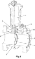
- the axial conduit (2) determines a main chamber in the flow meter in which the plate (3) provided with the orifice (4) is arranged in the normal functional position, as can be seen in Figures 3 and 4 , said main chamber being communicated through a passage (5) with an accessory chamber (6), which is closed by a cover (7) that can be removed to leave it open to the outside.
- a practicable sealing closure is arranged between an open position and a closed position, such that when it is necessary to extract the plate (3) in order to inspect or replace it due to the wear of the orifice (4) by friction of the fluid passing there through in the flow meter application function, said plate (3) can be extracted from the main chamber defined by the axial conduit (2) to the accessory chamber (6), as shown in Figure 5 .
- the circulated fluid is prevented from passing to said accessory chamber (6) by closing the communication passage (5) between the axial conduit (2) and the accessory chamber (6), being able to remove the cover (7) to extract the plate (3), as depicted in Figure 2 , such that the plate (3) can be extracted and introduced without having to interrupt the fluid flow through the axial conduit (2).
- the seal of said passage (5) is established by means of the movement of the first closure element(8) in its housing (10) to the position in which it interrupts the passage (5) between the axial conduit (2) and the accessory chamber (6), as depicted in Figure 6 ; and a second seal complementary to the seal established by the first closure element (8) is established by means of the movement of the second closure element (9) in its housing (11) to the respective position in which it interrupts the passage (5), which determines a completely leak-tight closure which completely prevents any leak of the fluid circulating through the axial conduit (2) towards the accessory chamber (6).
- That leak-tightness provided by the dual closure of this system of the invention between the axial conduit (2) and the accessory chamber (6) allows securely extracting and incorporating the plate (3) of the flow meter without interrupting the fluid circulation, even in applications for high-pressure fluid conduits, or in environments where double isolation is a requirement on Health and Safety grounds.
- the closure elements (8 and 9) of the closure system of the passage (5) communicated with the main chamber defined by the axial conduit (2) and the accessory chamber (6) have respective controls (12 and 13) located on the outside of the flow meter, such that by actuating said controls (12 and 13) the aforementioned closure elements (8 and 9) of the closure system can move between their respective sealed and open positions for sealing and opening the passage (5) when necessary.
Landscapes
- Engineering & Computer Science (AREA)
- General Engineering & Computer Science (AREA)
- Physics & Mathematics (AREA)
- Fluid Mechanics (AREA)
- General Physics & Mathematics (AREA)
- Mechanical Engineering (AREA)
- Measuring Volume Flow (AREA)
- Measuring Fluid Pressure (AREA)
Description
- The present invention relates to measuring the flow of fluids (gas or liquid) in pipes, and particularly to flow measuring apparatus having a plate provided, with an orifice having a smaller section than the flow circulation pipe and comprising a dual chamber for removing the plate with an orifice without interrupting the flow circulation, proposing a closure system which allows establishing a completely leak-tight isolation between the two chambers of the device when the plate with an orifice is removed.
- To measure the flow of fluids circulating through pipes, flow meter devices which are intercalated in the pipe of application are known, there being several functional implementations of said devices.
- A conventional solution of the aforementioned flow meter devices includes a plate provided with an orifice having a smaller section than the fluid circulation pipe in which the flow meter device is incorporated, said orifice being concentric with the section of the pipe of application in the functional arrangement, such that the flow of the gas or fluid circulating through the pipe increases in speed as it passes through that orifice, the increase in speed creating a pressure differential that can be measured to calculate the volumetric flow of fluid according to the section of the pipe.
- In this functional arrangement the sharp edge of the orifice bore of the plate of these flow meter devices experiences wear due to the friction of the circulating gas or fluid, such that the plate with an orifice must be frequently removed for inspection, or replacement. Failure to replace or repair a plate exhibiting a worn sharp edge of the orifice manifests as increased percentage uncertainty in volumetric flow as is referenced within the standards ISO 5167-2:2003 section 5.1.7.2 and API 14-Section 3-Part 2.4.2.
- In some cases, however, the interruption of the fluid circulation through the pipes in which the flow is measured can be damaging, so meter devices provided with a dual chamber have been developed in which the plate provided with the orifice can be removed from the normal functional position in the device, into an accessory chamber provided with a closure which allows isolating it with respect to the main chamber in which said plate with an orifice is located in the normal functional position, the embodiments contemplated in
patents US 1,996,192 ,US 2005/0258389 andUS 2007/0186987 , for example, corresponding with this solution. - The known solutions of such flow meter devices having a plate with an orifice and having a dual chamber to allow the removal of the plate with an orifice without interrupting the flow of the fluid through the pipe of application include a simple closure between the main chamber and the accessory chamber, whereby complete isolation leak-tightness between the chambers of the meter device is not assured, therefore these devices are not suitable for using in high-pressure fluid conduits, or for environments that demand a second method by which isolation can achieved, supported by visual evidence that such isolation has been both achieved and sustained.
- Example of a single wedge gate valve used to close off an access between two compartments is introduced in
EP0092910 . Here, the single valve seals off a chamber from gas flow in a pipeline. - Another was to seal two chambers to avoid fluid leakage is disclosed in
US5778933 . - According to the invention, a closure system for establishing the isolation between the dual chamber of flow meters having a plate with an orifice susceptible to being extracted without interrupting gas or fluid circulation passing through, which allows determining a completely leak-tight isolation with a visible means of between the two chambers when the plate with an orifice is extracted, is proposed.
- The objective of the invention is determined with two independent closure elements which are arranged in respective superimposed positions between the two chambers of the corresponding flow meter, said closure elements having respective operating controls which allow the individual movement thereof from the outside between respective open and closed positions of each of them.
- The two independent closure elements are arranged in a sliding assembly in corresponding housings, with the possibility of movement between a sealed position for sealing the passage between the two chambers of the flow meter and an offset position with respect to said passage.
- A closure system is thus obtained which, when the plate with an orifice of the flow meter is removed, from the main chamber where it is normally located in the functional position into the accessory extraction chamber, by means of moving one of the closure elements to the closed position, a seal is established in the passage between the two chambers, while the movement of the other closure element to the closed position assures complete leak-tightness of the seal, completely preventing the possibility of leaks between the two chambers, such that the flow meter is applicable for high-pressure fluid conduits, with the possibility of extracting and incorporating the plate with an orifice in a completely secure manner without having to interrupt the flow of the fluid since the dual closure system completely prevents leaks. This solution also satisfies the requirement of providing double isolation for health and safety purposes.
- The closure system of the invention therefore has very advantageous features for the functional capacity of the flow meters for which it is intended, its application in said flow meters acquiring its own identity and preferred character.
-
-
Figure 1 shows an outer perspective view of a flow meter provided with the closure system object of the invention. -
Figure 2 shows a perspective view of the flow meter with the plate with an orifice in the position for being extracted. -
Figure 3 shows a vertical cross-section perspective view of the flow meter with the plate with an orifice located in the normal functional position in the main chamber. -
Figure 4 shows a vertical longitudinal-section perspective view of the flow meter with the plate with an orifice located in the normal functional position in the main chamber, the closure elements of the passage between the main chamber and the accessory chamber being observed in the open position. -
Figure 5 shows a vertical cross-section of the flow meter with the plate with an orifice extracted into the accessory chamber. -
Figure 6 shows a vertical longitudinal-section perspective view of the flow meter with the plate with an orifice extracted into the accessory chamber and the passage between the main chamber and the accessory chamber sealed by an element of the closure system, the other element of the closure system being in the open position. -
Figure 7 shows a vertical longitudinal-section perspective view of the flow meter with the plate with an orifice extracted into the accessory chamber and the passage between the main chamber and the accessory chamber sealed by the two elements of the closure system. - The object of the invention relates to a closure system for flow meters comprising a body (1) longitudinally provided with an axial conduit (2) corresponding in diameter with a fluid (gas or liquid) circulation pipe the flow of which is to be measured, a plate (3) provided with an orifice (4) having a smaller section than the axial conduit (2) being transversely incorporated in the axial conduit (2).
- These flow meters are intercalated in the fluid circulation pipe the flow of which is to be measured, such that when the fluid passes through the orifice (4) of the plate (3) the flow increases in speed, giving rise to a pressure differential the measurement of which allows determining the volumetric flow of the fluid.
- The axial conduit (2) determines a main chamber in the flow meter in which the plate (3) provided with the orifice (4) is arranged in the normal functional position, as can be seen in
Figures 3 and4 , said main chamber being communicated through a passage (5) with an accessory chamber (6), which is closed by a cover (7) that can be removed to leave it open to the outside. - With respect to the passage (5) communicating the main chamber defined by the axial conduit (2) with the accessory chamber (6), a practicable sealing closure is arranged between an open position and a closed position, such that when it is necessary to extract the plate (3) in order to inspect or replace it due to the wear of the orifice (4) by friction of the fluid passing there through in the flow meter application function, said plate (3) can be extracted from the main chamber defined by the axial conduit (2) to the accessory chamber (6), as shown in
Figure 5 . - Once this is done, the circulated fluid is prevented from passing to said accessory chamber (6) by closing the communication passage (5) between the axial conduit (2) and the accessory chamber (6), being able to remove the cover (7) to extract the plate (3), as depicted in
Figure 2 , such that the plate (3) can be extracted and introduced without having to interrupt the fluid flow through the axial conduit (2). - According to the invention, there is arranged between the main chamber defined by the axial conduit (2) and the accessory chamber (6) a closure formed by two independent closure members (8 and 9) which are included in respective housings (10 and 11) intersecting the communication passage (5) between the axial conduit (2) and the accessory chamber (6) with the possibility of movement of each of said closure elements (8 and 9) in their respective housings (10 and 11) between a position in which they do not interfere with the aforementioned passage (5) between the axial conduit (2) and the accessory chamber (6) and a position in which they interrupt said passage (5).
- Therefore, when the plate (3) is in the accessory chamber (6), the seal of said passage (5) is established by means of the movement of the first closure element(8) in its housing (10) to the position in which it interrupts the passage (5) between the axial conduit (2) and the accessory chamber (6), as depicted in
Figure 6 ; and a second seal complementary to the seal established by the first closure element (8) is established by means of the movement of the second closure element (9) in its housing (11) to the respective position in which it interrupts the passage (5), which determines a completely leak-tight closure which completely prevents any leak of the fluid circulating through the axial conduit (2) towards the accessory chamber (6). - That leak-tightness provided by the dual closure of this system of the invention between the axial conduit (2) and the accessory chamber (6) allows securely extracting and incorporating the plate (3) of the flow meter without interrupting the fluid circulation, even in applications for high-pressure fluid conduits, or in environments where double isolation is a requirement on Health and Safety grounds.
- The closure elements (8 and 9) of the closure system of the passage (5) communicated with the main chamber defined by the axial conduit (2) and the accessory chamber (6) have respective controls (12 and 13) located on the outside of the flow meter, such that by actuating said controls (12 and 13) the aforementioned closure elements (8 and 9) of the closure system can move between their respective sealed and open positions for sealing and opening the passage (5) when necessary.
Claims (2)
- Double chamber differential pressure meter with a double isolation system, the meter comprising an axial fluid circulation conduit (2), in which the fluid to be measured flows, an accessory chamber (6), a communication passage (5), which is placed between said axial fluid circulation conduit (2) and said accessory chamber (6),
wherein the differential pressure meter further comprises a plate (3) provided with an orifice (4) having a smaller section than said axial conduit (2), which is transversely arranged in the axial conduit (2) and which can be extracted into the accessory chamber (6) to be removed without interrupting the flow of the fluid through the axial conduit (2),
characterized in that
the differential pressure meter further comprises a closure formed by two independent closure elements (8 and 9) in their respective housings (10 and 11), which is arranged in relation to the communication passage (5) between the axial conduit (2) and the accessory chamber (6) in such a way that each one of the closure elements intersects-the passage (5) independently with the possibility of movement of each of said closure elements (8 and 9) in their respective housings (10 and 11) between a position in which they do not interfere with the aforementioned passage (5) and a position in which they interrupt said passage (5), establishing a dual closure between both closure elements (8 and 9) and the passage (5) and determining a leak-tight seal for that passage (5). - Double chamber differential pressure meter with a double isolation system according to claim 1, characterized in that the closure elements (8 and 9) have respective controls (12 and 13) located on the outside by means of which the movement of said closure elements (8 and 9) between their respective sealed and open positions for sealing and opening the passage (5) can be actuated.
Applications Claiming Priority (1)
| Application Number | Priority Date | Filing Date | Title |
|---|---|---|---|
| PCT/ES2011/000066 WO2012120158A1 (en) | 2011-03-09 | 2011-03-09 | Double closure for double-chamber differential pressure measurement device |
Publications (3)
| Publication Number | Publication Date |
|---|---|
| EP2657660A1 EP2657660A1 (en) | 2013-10-30 |
| EP2657660A4 EP2657660A4 (en) | 2014-08-27 |
| EP2657660B1 true EP2657660B1 (en) | 2017-06-21 |
Family
ID=46797520
Family Applications (1)
| Application Number | Title | Priority Date | Filing Date |
|---|---|---|---|
| EP11860150.9A Not-in-force EP2657660B1 (en) | 2011-03-09 | 2011-03-09 | Double-chamber differential pressure measurement device with a double closure system |
Country Status (9)
| Country | Link |
|---|---|
| US (1) | US9310235B2 (en) |
| EP (1) | EP2657660B1 (en) |
| CN (1) | CN103477195A (en) |
| BR (1) | BR112013006085A2 (en) |
| CA (1) | CA2810121C (en) |
| MY (1) | MY168309A (en) |
| RU (1) | RU2558008C2 (en) |
| SG (1) | SG188341A1 (en) |
| WO (1) | WO2012120158A1 (en) |
Families Citing this family (5)
| Publication number | Priority date | Publication date | Assignee | Title |
|---|---|---|---|---|
| MY183270A (en) | 2013-02-15 | 2021-02-18 | Derold Clark | Method and apparatus for installing and removing a flow restrictor from a differential pressure measurement device |
| JP6039528B2 (en) * | 2013-10-21 | 2016-12-07 | 岡山市 | Valve lid removal method, valve removal method and valve lid attachment for gate valve |
| DE102014203043B3 (en) * | 2014-02-19 | 2015-03-05 | Minimax Gmbh & Co. Kg | Löschfluiddüsensystem, in particular extinguishing gas nozzle system for stationary fire extinguishing systems, as well as extinguishing fluid nozzle and -blende for selbiges |
| CA2853935C (en) | 2014-06-09 | 2019-09-24 | Derold Gary Clark | Valve strip retainer assembly |
| MX389682B (en) * | 2014-12-12 | 2025-03-20 | Daniel Opco Llc | MULTI-DOUBLE LOCK AND BLEED SYSTEM FOR ONE CONNECTOR HOLE |
Citations (1)
| Publication number | Priority date | Publication date | Assignee | Title |
|---|---|---|---|---|
| US5778933A (en) * | 1995-03-15 | 1998-07-14 | Crane Manufacturing, Inc. | Orifice fitting |
Family Cites Families (25)
| Publication number | Priority date | Publication date | Assignee | Title |
|---|---|---|---|---|
| US1938460A (en) | 1933-12-05 | Orifice fitting | ||
| US1996192A (en) | 1935-04-02 | daniel | ||
| US2050544A (en) * | 1935-09-17 | 1936-08-11 | Robinson Orifice Fitting Compa | Orifice meter fitting |
| GB911312A (en) * | 1959-12-04 | 1962-11-21 | Ernest Reginald Garrod | Improvements in or relating to fluid control valves |
| FR2138265B1 (en) | 1971-05-21 | 1973-05-25 | Peugeot & Renault | |
| US3817287A (en) * | 1972-03-20 | 1974-06-18 | M Aitken | Orifice fitting |
| US4007906A (en) * | 1974-01-14 | 1977-02-15 | Anchor/Darling Valve Company | Main steam isolation valve |
| US4275763A (en) | 1979-05-25 | 1981-06-30 | Standard Oil Company (Indiana) | Double-slide valve |
| US4425806A (en) | 1982-03-29 | 1984-01-17 | Grove Valve And Regulator Company | Modular orifice meter with isolation chamber valve closure |
| DE3227697C2 (en) * | 1982-07-24 | 1984-06-07 | C.H. Zikesch GmbH, 4100 Duisburg | Device for exchanging a measuring orifice switched on in a pipeline |
| CH659602A5 (en) * | 1982-08-24 | 1987-02-13 | Stopinc Ag | METHOD FOR PRODUCING A SEALING ARRANGEMENT ON A SLIDING LOCK. |
| US5186474A (en) * | 1991-12-03 | 1993-02-16 | Jacobs James L | Seal ring for orifice plate |
| US5464036A (en) * | 1994-02-09 | 1995-11-07 | Valgro, Ltd. | Orifice fitting with venting passage and injection seal |
| US5474103A (en) * | 1995-03-22 | 1995-12-12 | Klak; Steven P. | Safety guard for orifice fitting device |
| US5836356A (en) | 1996-03-12 | 1998-11-17 | Mueller Steam Specialty, A Divison Of Core Industries, Inc. | Dual chamber orifice fitting |
| US5967166A (en) * | 1998-01-23 | 1999-10-19 | Daniel Industries, Inc. | Sealing assembly and method |
| GB0024507D0 (en) * | 2000-10-06 | 2000-11-22 | Oliver Twinsafe Valves Ltd | An isolation valve assembly |
| US6871666B1 (en) * | 2004-05-19 | 2005-03-29 | Daniel Industries, Inc. | Bi-directional dual chamber orifice fitting |
| US7104521B2 (en) * | 2004-05-19 | 2006-09-12 | Daniel Industries, Inc. | Dual chamber orifice fitting valve |
| US7063107B2 (en) * | 2004-05-19 | 2006-06-20 | Daniel Industries, Inc. | Dual chamber orifice fitting body |
| US7837176B2 (en) * | 2004-05-19 | 2010-11-23 | Daniel Measurement And Control, Inc. | Dual chamber orifice fitting plate support |
| US7870873B2 (en) * | 2006-02-13 | 2011-01-18 | Daniel Industries, Inc. | Dual chamber orifice fitting isolation valve |
| CN201083275Y (en) * | 2007-03-27 | 2008-07-09 | 曹剑钢 | Slag-removing gate valve |
| US20090194182A1 (en) * | 2008-01-31 | 2009-08-06 | Daniel Measurement And Control, Inc. | Dual chamber orifice fitting body |
| MY183270A (en) | 2013-02-15 | 2021-02-18 | Derold Clark | Method and apparatus for installing and removing a flow restrictor from a differential pressure measurement device |
-
2011
- 2011-03-09 BR BR112013006085A patent/BR112013006085A2/en active Search and Examination
- 2011-03-09 US US13/822,157 patent/US9310235B2/en not_active Expired - Fee Related
- 2011-03-09 RU RU2013132955/28A patent/RU2558008C2/en not_active IP Right Cessation
- 2011-03-09 CA CA2810121A patent/CA2810121C/en not_active Expired - Fee Related
- 2011-03-09 EP EP11860150.9A patent/EP2657660B1/en not_active Not-in-force
- 2011-03-09 MY MYPI2013000855A patent/MY168309A/en unknown
- 2011-03-09 WO PCT/ES2011/000066 patent/WO2012120158A1/en not_active Ceased
- 2011-03-09 SG SG2013015177A patent/SG188341A1/en unknown
- 2011-03-09 CN CN2011800673294A patent/CN103477195A/en active Pending
Patent Citations (1)
| Publication number | Priority date | Publication date | Assignee | Title |
|---|---|---|---|---|
| US5778933A (en) * | 1995-03-15 | 1998-07-14 | Crane Manufacturing, Inc. | Orifice fitting |
Also Published As
| Publication number | Publication date |
|---|---|
| CA2810121F (en) | 2012-09-13 |
| SG188341A1 (en) | 2013-04-30 |
| WO2012120158A1 (en) | 2012-09-13 |
| EP2657660A4 (en) | 2014-08-27 |
| RU2013132955A (en) | 2015-04-20 |
| US20130180614A1 (en) | 2013-07-18 |
| US9310235B2 (en) | 2016-04-12 |
| RU2558008C2 (en) | 2015-07-27 |
| CA2810121C (en) | 2014-03-11 |
| CA2810121A1 (en) | 2012-09-13 |
| EP2657660A1 (en) | 2013-10-30 |
| MY168309A (en) | 2018-10-29 |
| CN103477195A (en) | 2013-12-25 |
| BR112013006085A2 (en) | 2016-06-07 |
Similar Documents
| Publication | Publication Date | Title |
|---|---|---|
| CA2810121C (en) | Double isolation for double chamber differential pressure meter | |
| EP4222397B1 (en) | Valve diagnostic and performance system | |
| EP3230695B1 (en) | Multi- double block and bleed system for an orifice fitting | |
| RU2468278C2 (en) | Connection element for connection of two ends of pipes | |
| AU2013215321A1 (en) | Sensor-enabled gate valve | |
| CA2993298C (en) | Double block and bleed system for an orifice fitting | |
| NO20131699A1 (en) | Gasket for compact pipe flange | |
| EP4222398A1 (en) | Valve diagnostic and performance system | |
| RU2738295C2 (en) | Unit for start-up test of fluid flow regulators at different pressure and temperature values | |
| RU2566359C2 (en) | Sight channel of pressure release of regulating valve | |
| CA2886065C (en) | High-pressure valve | |
| US10533669B2 (en) | Bi-directional flow control valve | |
| CN208921380U (en) | DBB valve leak detecting device | |
| RU2016130676A (en) | VALVE SHAFT DEVICE FOR APPLICATION IN ROTARY VALVES | |
| CN104458143A (en) | Valve leakage detection table | |
| KR20170075131A (en) | Device for confirming flow of fluid | |
| KR200472914Y1 (en) | Semi-medium pressure valve | |
| US8127792B2 (en) | Pressure equalization system for a bi-directional orifice fitting | |
| WO2017027001A1 (en) | Multi-seat valve | |
| CA3003880C (en) | Assembly for start-up testing fluid flow control devices at various pressures and temperatures | |
| KR20130056720A (en) | Stop valve for indicating internal pressure using a pressure difference |
Legal Events
| Date | Code | Title | Description |
|---|---|---|---|
| PUAI | Public reference made under article 153(3) epc to a published international application that has entered the european phase |
Free format text: ORIGINAL CODE: 0009012 |
|
| 17P | Request for examination filed |
Effective date: 20130305 |
|
| AK | Designated contracting states |
Kind code of ref document: A1 Designated state(s): AL AT BE BG CH CY CZ DE DK EE ES FI FR GB GR HR HU IE IS IT LI LT LU LV MC MK MT NL NO PL PT RO RS SE SI SK SM TR |
|
| DAX | Request for extension of the european patent (deleted) | ||
| REG | Reference to a national code |
Ref country code: DE Ref legal event code: R079 Ref document number: 602011039026 Country of ref document: DE Free format text: PREVIOUS MAIN CLASS: G01F0001880000 Ipc: G01F0001420000 |
|
| A4 | Supplementary search report drawn up and despatched |
Effective date: 20140724 |
|
| RIC1 | Information provided on ipc code assigned before grant |
Ipc: G01F 1/42 20060101AFI20140718BHEP Ipc: F16K 3/02 20060101ALI20140718BHEP Ipc: G01F 1/38 20060101ALI20140718BHEP |
|
| TPAC | Observations filed by third parties |
Free format text: ORIGINAL CODE: EPIDOSNTIPA |
|
| 17Q | First examination report despatched |
Effective date: 20160408 |
|
| GRAP | Despatch of communication of intention to grant a patent |
Free format text: ORIGINAL CODE: EPIDOSNIGR1 |
|
| STAA | Information on the status of an ep patent application or granted ep patent |
Free format text: STATUS: GRANT OF PATENT IS INTENDED |
|
| INTG | Intention to grant announced |
Effective date: 20170103 |
|
| GRAS | Grant fee paid |
Free format text: ORIGINAL CODE: EPIDOSNIGR3 |
|
| GRAA | (expected) grant |
Free format text: ORIGINAL CODE: 0009210 |
|
| STAA | Information on the status of an ep patent application or granted ep patent |
Free format text: STATUS: THE PATENT HAS BEEN GRANTED |
|
| AK | Designated contracting states |
Kind code of ref document: B1 Designated state(s): AL AT BE BG CH CY CZ DE DK EE ES FI FR GB GR HR HU IE IS IT LI LT LU LV MC MK MT NL NO PL PT RO RS SE SI SK SM TR |
|
| REG | Reference to a national code |
Ref country code: GB Ref legal event code: FG4D |
|
| REG | Reference to a national code |
Ref country code: CH Ref legal event code: EP |
|
| REG | Reference to a national code |
Ref country code: IE Ref legal event code: FG4D |
|
| REG | Reference to a national code |
Ref country code: AT Ref legal event code: REF Ref document number: 903380 Country of ref document: AT Kind code of ref document: T Effective date: 20170715 |
|
| REG | Reference to a national code |
Ref country code: DE Ref legal event code: R096 Ref document number: 602011039026 Country of ref document: DE |
|
| REG | Reference to a national code |
Ref country code: NL Ref legal event code: MP Effective date: 20170621 |
|
| PG25 | Lapsed in a contracting state [announced via postgrant information from national office to epo] |
Ref country code: LT Free format text: LAPSE BECAUSE OF FAILURE TO SUBMIT A TRANSLATION OF THE DESCRIPTION OR TO PAY THE FEE WITHIN THE PRESCRIBED TIME-LIMIT Effective date: 20170621 Ref country code: FI Free format text: LAPSE BECAUSE OF FAILURE TO SUBMIT A TRANSLATION OF THE DESCRIPTION OR TO PAY THE FEE WITHIN THE PRESCRIBED TIME-LIMIT Effective date: 20170621 Ref country code: NO Free format text: LAPSE BECAUSE OF FAILURE TO SUBMIT A TRANSLATION OF THE DESCRIPTION OR TO PAY THE FEE WITHIN THE PRESCRIBED TIME-LIMIT Effective date: 20170921 Ref country code: HR Free format text: LAPSE BECAUSE OF FAILURE TO SUBMIT A TRANSLATION OF THE DESCRIPTION OR TO PAY THE FEE WITHIN THE PRESCRIBED TIME-LIMIT Effective date: 20170621 |
|
| REG | Reference to a national code |
Ref country code: LT Ref legal event code: MG4D |
|
| REG | Reference to a national code |
Ref country code: AT Ref legal event code: MK05 Ref document number: 903380 Country of ref document: AT Kind code of ref document: T Effective date: 20170621 |
|
| PG25 | Lapsed in a contracting state [announced via postgrant information from national office to epo] |
Ref country code: RS Free format text: LAPSE BECAUSE OF FAILURE TO SUBMIT A TRANSLATION OF THE DESCRIPTION OR TO PAY THE FEE WITHIN THE PRESCRIBED TIME-LIMIT Effective date: 20170621 Ref country code: SE Free format text: LAPSE BECAUSE OF FAILURE TO SUBMIT A TRANSLATION OF THE DESCRIPTION OR TO PAY THE FEE WITHIN THE PRESCRIBED TIME-LIMIT Effective date: 20170621 Ref country code: LV Free format text: LAPSE BECAUSE OF FAILURE TO SUBMIT A TRANSLATION OF THE DESCRIPTION OR TO PAY THE FEE WITHIN THE PRESCRIBED TIME-LIMIT Effective date: 20170621 Ref country code: BG Free format text: LAPSE BECAUSE OF FAILURE TO SUBMIT A TRANSLATION OF THE DESCRIPTION OR TO PAY THE FEE WITHIN THE PRESCRIBED TIME-LIMIT Effective date: 20170921 Ref country code: NL Free format text: LAPSE BECAUSE OF FAILURE TO SUBMIT A TRANSLATION OF THE DESCRIPTION OR TO PAY THE FEE WITHIN THE PRESCRIBED TIME-LIMIT Effective date: 20170621 |
|
| PG25 | Lapsed in a contracting state [announced via postgrant information from national office to epo] |
Ref country code: CZ Free format text: LAPSE BECAUSE OF FAILURE TO SUBMIT A TRANSLATION OF THE DESCRIPTION OR TO PAY THE FEE WITHIN THE PRESCRIBED TIME-LIMIT Effective date: 20170621 Ref country code: RO Free format text: LAPSE BECAUSE OF FAILURE TO SUBMIT A TRANSLATION OF THE DESCRIPTION OR TO PAY THE FEE WITHIN THE PRESCRIBED TIME-LIMIT Effective date: 20170621 Ref country code: SK Free format text: LAPSE BECAUSE OF FAILURE TO SUBMIT A TRANSLATION OF THE DESCRIPTION OR TO PAY THE FEE WITHIN THE PRESCRIBED TIME-LIMIT Effective date: 20170621 Ref country code: AT Free format text: LAPSE BECAUSE OF FAILURE TO SUBMIT A TRANSLATION OF THE DESCRIPTION OR TO PAY THE FEE WITHIN THE PRESCRIBED TIME-LIMIT Effective date: 20170621 Ref country code: EE Free format text: LAPSE BECAUSE OF FAILURE TO SUBMIT A TRANSLATION OF THE DESCRIPTION OR TO PAY THE FEE WITHIN THE PRESCRIBED TIME-LIMIT Effective date: 20170621 |
|
| PG25 | Lapsed in a contracting state [announced via postgrant information from national office to epo] |
Ref country code: SM Free format text: LAPSE BECAUSE OF FAILURE TO SUBMIT A TRANSLATION OF THE DESCRIPTION OR TO PAY THE FEE WITHIN THE PRESCRIBED TIME-LIMIT Effective date: 20170621 Ref country code: PL Free format text: LAPSE BECAUSE OF FAILURE TO SUBMIT A TRANSLATION OF THE DESCRIPTION OR TO PAY THE FEE WITHIN THE PRESCRIBED TIME-LIMIT Effective date: 20170621 Ref country code: ES Free format text: LAPSE BECAUSE OF FAILURE TO SUBMIT A TRANSLATION OF THE DESCRIPTION OR TO PAY THE FEE WITHIN THE PRESCRIBED TIME-LIMIT Effective date: 20170621 Ref country code: IS Free format text: LAPSE BECAUSE OF FAILURE TO SUBMIT A TRANSLATION OF THE DESCRIPTION OR TO PAY THE FEE WITHIN THE PRESCRIBED TIME-LIMIT Effective date: 20171021 |
|
| REG | Reference to a national code |
Ref country code: DE Ref legal event code: R097 Ref document number: 602011039026 Country of ref document: DE |
|
| PLBE | No opposition filed within time limit |
Free format text: ORIGINAL CODE: 0009261 |
|
| STAA | Information on the status of an ep patent application or granted ep patent |
Free format text: STATUS: NO OPPOSITION FILED WITHIN TIME LIMIT |
|
| PG25 | Lapsed in a contracting state [announced via postgrant information from national office to epo] |
Ref country code: DK Free format text: LAPSE BECAUSE OF FAILURE TO SUBMIT A TRANSLATION OF THE DESCRIPTION OR TO PAY THE FEE WITHIN THE PRESCRIBED TIME-LIMIT Effective date: 20170621 |
|
| 26N | No opposition filed |
Effective date: 20180322 |
|
| PG25 | Lapsed in a contracting state [announced via postgrant information from national office to epo] |
Ref country code: SI Free format text: LAPSE BECAUSE OF FAILURE TO SUBMIT A TRANSLATION OF THE DESCRIPTION OR TO PAY THE FEE WITHIN THE PRESCRIBED TIME-LIMIT Effective date: 20170621 |
|
| REG | Reference to a national code |
Ref country code: DE Ref legal event code: R119 Ref document number: 602011039026 Country of ref document: DE |
|
| REG | Reference to a national code |
Ref country code: CH Ref legal event code: PL |
|
| GBPC | Gb: european patent ceased through non-payment of renewal fee |
Effective date: 20180309 |
|
| PG25 | Lapsed in a contracting state [announced via postgrant information from national office to epo] |
Ref country code: MC Free format text: LAPSE BECAUSE OF FAILURE TO SUBMIT A TRANSLATION OF THE DESCRIPTION OR TO PAY THE FEE WITHIN THE PRESCRIBED TIME-LIMIT Effective date: 20170621 |
|
| REG | Reference to a national code |
Ref country code: BE Ref legal event code: MM Effective date: 20180331 |
|
| REG | Reference to a national code |
Ref country code: IE Ref legal event code: MM4A |
|
| PG25 | Lapsed in a contracting state [announced via postgrant information from national office to epo] |
Ref country code: LU Free format text: LAPSE BECAUSE OF NON-PAYMENT OF DUE FEES Effective date: 20180309 |
|
| PG25 | Lapsed in a contracting state [announced via postgrant information from national office to epo] |
Ref country code: IE Free format text: LAPSE BECAUSE OF NON-PAYMENT OF DUE FEES Effective date: 20180309 Ref country code: DE Free format text: LAPSE BECAUSE OF NON-PAYMENT OF DUE FEES Effective date: 20181002 |
|
| PG25 | Lapsed in a contracting state [announced via postgrant information from national office to epo] |
Ref country code: CH Free format text: LAPSE BECAUSE OF NON-PAYMENT OF DUE FEES Effective date: 20180331 Ref country code: LI Free format text: LAPSE BECAUSE OF NON-PAYMENT OF DUE FEES Effective date: 20180331 Ref country code: GB Free format text: LAPSE BECAUSE OF NON-PAYMENT OF DUE FEES Effective date: 20180309 Ref country code: BE Free format text: LAPSE BECAUSE OF NON-PAYMENT OF DUE FEES Effective date: 20180331 |
|
| PG25 | Lapsed in a contracting state [announced via postgrant information from national office to epo] |
Ref country code: FR Free format text: LAPSE BECAUSE OF NON-PAYMENT OF DUE FEES Effective date: 20180331 |
|
| PGFP | Annual fee paid to national office [announced via postgrant information from national office to epo] |
Ref country code: IT Payment date: 20190328 Year of fee payment: 9 |
|
| PG25 | Lapsed in a contracting state [announced via postgrant information from national office to epo] |
Ref country code: MT Free format text: LAPSE BECAUSE OF NON-PAYMENT OF DUE FEES Effective date: 20180309 |
|
| PG25 | Lapsed in a contracting state [announced via postgrant information from national office to epo] |
Ref country code: TR Free format text: LAPSE BECAUSE OF FAILURE TO SUBMIT A TRANSLATION OF THE DESCRIPTION OR TO PAY THE FEE WITHIN THE PRESCRIBED TIME-LIMIT Effective date: 20170621 |
|
| PG25 | Lapsed in a contracting state [announced via postgrant information from national office to epo] |
Ref country code: HU Free format text: LAPSE BECAUSE OF FAILURE TO SUBMIT A TRANSLATION OF THE DESCRIPTION OR TO PAY THE FEE WITHIN THE PRESCRIBED TIME-LIMIT; INVALID AB INITIO Effective date: 20110309 Ref country code: PT Free format text: LAPSE BECAUSE OF FAILURE TO SUBMIT A TRANSLATION OF THE DESCRIPTION OR TO PAY THE FEE WITHIN THE PRESCRIBED TIME-LIMIT Effective date: 20170621 |
|
| PG25 | Lapsed in a contracting state [announced via postgrant information from national office to epo] |
Ref country code: GR Free format text: LAPSE BECAUSE OF FAILURE TO SUBMIT A TRANSLATION OF THE DESCRIPTION OR TO PAY THE FEE WITHIN THE PRESCRIBED TIME-LIMIT Effective date: 20170621 Ref country code: MK Free format text: LAPSE BECAUSE OF NON-PAYMENT OF DUE FEES Effective date: 20170621 Ref country code: CY Free format text: LAPSE BECAUSE OF FAILURE TO SUBMIT A TRANSLATION OF THE DESCRIPTION OR TO PAY THE FEE WITHIN THE PRESCRIBED TIME-LIMIT Effective date: 20170621 |
|
| PG25 | Lapsed in a contracting state [announced via postgrant information from national office to epo] |
Ref country code: AL Free format text: LAPSE BECAUSE OF FAILURE TO SUBMIT A TRANSLATION OF THE DESCRIPTION OR TO PAY THE FEE WITHIN THE PRESCRIBED TIME-LIMIT Effective date: 20170621 |
|
| PG25 | Lapsed in a contracting state [announced via postgrant information from national office to epo] |
Ref country code: IT Free format text: LAPSE BECAUSE OF NON-PAYMENT OF DUE FEES Effective date: 20200309 |