EP2657607A2 - Combustor apparatus for stoichiometric combustion - Google Patents
Combustor apparatus for stoichiometric combustion Download PDFInfo
- Publication number
- EP2657607A2 EP2657607A2 EP13164765.3A EP13164765A EP2657607A2 EP 2657607 A2 EP2657607 A2 EP 2657607A2 EP 13164765 A EP13164765 A EP 13164765A EP 2657607 A2 EP2657607 A2 EP 2657607A2
- Authority
- EP
- European Patent Office
- Prior art keywords
- liner
- combustor according
- combustor
- holes
- working fluid
- Prior art date
- Legal status (The legal status is an assumption and is not a legal conclusion. Google has not performed a legal analysis and makes no representation as to the accuracy of the status listed.)
- Withdrawn
Links
- 238000002485 combustion reaction Methods 0.000 title abstract description 16
- 239000012530 fluid Substances 0.000 claims abstract description 23
- 239000007800 oxidant agent Substances 0.000 claims abstract description 11
- 238000002156 mixing Methods 0.000 claims description 22
- 238000010790 dilution Methods 0.000 claims description 14
- 239000012895 dilution Substances 0.000 claims description 14
- 238000001816 cooling Methods 0.000 claims description 4
- 230000035515 penetration Effects 0.000 claims description 4
- 239000000446 fuel Substances 0.000 abstract description 14
- 239000007789 gas Substances 0.000 abstract description 14
- QVGXLLKOCUKJST-UHFFFAOYSA-N atomic oxygen Chemical compound [O] QVGXLLKOCUKJST-UHFFFAOYSA-N 0.000 abstract description 7
- 229910052760 oxygen Inorganic materials 0.000 abstract description 7
- 239000001301 oxygen Substances 0.000 abstract description 7
- 230000002950 deficient Effects 0.000 abstract description 2
- 238000009792 diffusion process Methods 0.000 abstract description 2
- 238000006243 chemical reaction Methods 0.000 description 6
- 239000003085 diluting agent Substances 0.000 description 3
- OKTJSMMVPCPJKN-UHFFFAOYSA-N Carbon Chemical compound [C] OKTJSMMVPCPJKN-UHFFFAOYSA-N 0.000 description 2
- 229910052799 carbon Inorganic materials 0.000 description 2
- 230000001737 promoting effect Effects 0.000 description 2
- 238000010494 dissociation reaction Methods 0.000 description 1
- 230000005593 dissociations Effects 0.000 description 1
- 238000002347 injection Methods 0.000 description 1
- 239000007924 injection Substances 0.000 description 1
- 239000007788 liquid Substances 0.000 description 1
- 238000012986 modification Methods 0.000 description 1
- 230000004048 modification Effects 0.000 description 1
- 238000010791 quenching Methods 0.000 description 1
- 230000000171 quenching effect Effects 0.000 description 1
- 239000000243 solution Substances 0.000 description 1
Images


Classifications
-
- F—MECHANICAL ENGINEERING; LIGHTING; HEATING; WEAPONS; BLASTING
- F23—COMBUSTION APPARATUS; COMBUSTION PROCESSES
- F23R—GENERATING COMBUSTION PRODUCTS OF HIGH PRESSURE OR HIGH VELOCITY, e.g. GAS-TURBINE COMBUSTION CHAMBERS
- F23R3/00—Continuous combustion chambers using liquid or gaseous fuel
- F23R3/02—Continuous combustion chambers using liquid or gaseous fuel characterised by the air-flow or gas-flow configuration
- F23R3/04—Air inlet arrangements
- F23R3/06—Arrangement of apertures along the flame tube
Definitions
- the present invention relates to a gas turbine combustor geometry with a specific fuel and oxidizer flow arrangement that provides high combustion efficiency for stoichiometric diffusion combustion in gas turbine applications operating with oxygen-deficient working fluids.
- Gas turbine applications utilizing low oxygen working fluids are known. Examples of such applications are carbon capture, oxyfuel, and high exhaust gas recirculation, all of which require high combustion efficiency to be economically viable. However, achieving such high combustion efficiency has not been attainable to date.
- the present invention seeks to satisfy that need.
- the invention provides a combustor comprising a housing having an inner surface, an interior volume, and a nozzle and a liner assembly positioned within the housing.
- the liner is provided with at least one liner mixing hole and at least one liner dilution hole.
- the liner assembly is spaced apart from the inner surface of the housing to define a path extending longitudinally along the combustor between the liner assembly and the inner surface of the housing for transporting working fluid to the interior volume through the liner mixing and dilution holes.
- the liner mixing and dilution holes are axially positioned in the liner assembly at specific positions as a function of the diameter of the liner.
- the combustor of the invention provides a stable flame and high combustion efficiency while ensuring adequate hardware durability. Since the applications of carbon capture, oxyfuel, and high exhaust gas recirculation require near stoichiometric combustion, the combustor of the present invention provides high efficiency combustion to ensure combustion is completed before fuel and oxidizers are diluted with the gas turbine working fluid.
- the combustor of the invention thus provides a cost effective solution in gas turbine applications where a low oxygen working fluid is used to achieve improved combustion efficiency as compared to that obtained using conventional combustors.
- Figure 1 shows a perspective interior view of the combustor 2 of the invention having a housing 4 with an inner surface 6 and an interior volume 8.
- a liner assembly 10 is provided within the housing 4 and is spaced apart from the inner surface 6 of the housing to define a path 12 extending longitudinally along the length of the combustor 2 between the liner assembly 10 and the inner surface 6, along which gas turbine (GT) diluent rich working fluid flows.
- GT gas turbine
- Figures 1 and 3 also show a nozzle 14 provided at one end of the combustor 2.
- the nozzle 14 is in flow communication with the interior volume 8 of the combustor 2.
- the nozzle 14 is provided with a series of concentric apertures defining fuel holes 16.
- Figure 2 shows the liner assembly 10 provided with liner mixing holes 18,20, liner dilution holes 40,42 and liner cooling holes 44,46,48 at different axial locations along the liner 10.
- the liner mixing holes 18,20 are sized and positioned in the liner assembly 10 at axial locations to provide good mixing of fuel components and complete combustion.
- the liner mixing holes 18,20 are sized to provide about 10% of the GT flow, i.e., the flow available for the combustor from the compressor. Jets injected from the fuel nozzle through the liner mixing holes restrict the expansion of the oxidizer stream which promotes shear mixing between fuel and oxidizer.
- the location of the liner mixing holes may be optimized to avoid flame quenching. The is discussed below in relation to Figure 4 .
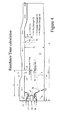
- Figure 4 shows the liner mixing holes 18, 20 situated at an axial distance L from the nozzle 14 which is typically 0.65-1.05D, where D is the internal diameter of the liner 10.
- the liner mixing holes generate a jet penetration into the interior volume 8 of the liner of 1.05-1.4 D1, where D1 is the diameter of the mixing hole.
- the cooling holes 44,46,48 are positioned at different axial locations and are designed to accommodate, for example, about 30-32% of the GT working fluid at compressor discharge (i.e., the exit station of the compressor and starting station of the combustor).
- the size and number of cooling holes at any particular location is based on the desired effective heat transfer at that location.
- Crown hole 28 accommodates about 6-9% of the GT working fluid at compressor discharge.
- the crown hole 28 creates a recirculation bubble 50 of length L2 of 0.65-1.05D where D is the internal diameter of the liner 10. This provides for higher combustion efficiency.
- the dilution holes 40,42 are situated at an axial distance L3 of 1.3-1.7 D, where D is the internal diameter of the liner.
- the dilution holes create a jet penetration of L4 which is 1.4-1.6 times D2, where D2 is the diameter of the dilution hole.
- Strong shear mixing occurs between the oxidizer and fuel resulting in rapid reaction with a short residence time promoting a larger reaction zone.
- the mixing with the GT working fluid helps in controlling the peak flame temperature while keeping the flame away from the nozzle.
- the dilution holes accommodate 8-11 % of the total combustor flow.
- the center passage 24 of the nozzle is generally used for oxidizer flow, such as air, oxygen, diluted oxygen or fuel.
- the outer passages 22,26 are intended for gas turbine (GT) working fluid (typically a diluent rich fluid).
- GT gas turbine
- the passages 22, 24, 26 are typically inclined such that they produce counter-rotating flow between the oxidizer and GT working fluid.
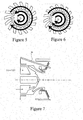
- Figure 5 illustrates schematically the gases exiting the nozzle into the interior volume 8 in a counter-swirling manner.
- Figure 6 illustrates an example of co-swirling where the gases exit the nozzle into the interior volume 8 in a co-swirling manner.
- the center passage 24 of the nozzle 14 typically contains angled fuel injection holes with an angle range from 40-60 degrees to produce high swirling flow.
- the center annular passage 24 of the nozzle is intended for gaseous fuel flow and is typically inclined with a cone angle of 20-26 degrees and a swirl angle of 5-16 degrees to the nozzle axis to induce counter-clockwise swirling (see Figure 5 ).
- the outer annular passage 26 is generally intended for diluent flow and is inclined with a cone angle of 30-36 degrees and swirl angle of 5-16 degrees to the nozzle axis to induce clockwise rotation. In such a flow arrangement, the strong shear mixing between the oxidizer and fuel results in the rapid reaction with a short residence time promoting larger reaction zone than in prior arrangements.
- the center passage 24 of the nozzle is designed to flow a blended fluid containing 20-80% of the oxidizer and 80-20% of the GT working fluid at compressor discharge.
- the blending is optimized to control the reaction rates, and flame temperature to lower the dissociation loss from the reaction zone.
- the outer passage 26 is designed to flow 25-30% of the total combustor flow. This flow arrangement acts to delay the combustion reaction downstream of the nozzle and thereby avoid potential risk of hardware damage.
- Figure 7 shows an integrated igniter 30 on the nozzle 14 for igniting the combustible charge.
- the igniter is typically located at an angle of 25-30 degrees to the nozzle longitudinal axis.
- a pilot nozzle 52 may alternatively be provided for startup application.
- the pilot nozzle if present, is usually located in the middle of the fuel nozzle that passes liquid fuel.
Landscapes
- Engineering & Computer Science (AREA)
- Chemical & Material Sciences (AREA)
- Combustion & Propulsion (AREA)
- Mechanical Engineering (AREA)
- General Engineering & Computer Science (AREA)
- Nozzles For Spraying Of Liquid Fuel (AREA)
- Turbine Rotor Nozzle Sealing (AREA)
- Gas Burners (AREA)
Abstract
Gas turbine combustor 2 with a specific fuel and oxidizer flow arrangement 12 which provides high combustion efficiency for stoichiometric diffusion combustion in gas turbine applications operating with oxygen deficient working fluids.
Description
- The present invention relates to a gas turbine combustor geometry with a specific fuel and oxidizer flow arrangement that provides high combustion efficiency for stoichiometric diffusion combustion in gas turbine applications operating with oxygen-deficient working fluids.
- Gas turbine applications utilizing low oxygen working fluids are known. Examples of such applications are carbon capture, oxyfuel, and high exhaust gas recirculation, all of which require high combustion efficiency to be economically viable. However, achieving such high combustion efficiency has not been attainable to date.
- A need exists for high efficiency combustion in gas turbine applications where a low oxygen working fluid is used. The present invention seeks to satisfy that need.
- In one aspect, the invention provides a combustor comprising a housing having an inner surface, an interior volume, and a nozzle and a liner assembly positioned within the housing. The liner is provided with at least one liner mixing hole and at least one liner dilution hole. The liner assembly is spaced apart from the inner surface of the housing to define a path extending longitudinally along the combustor between the liner assembly and the inner surface of the housing for transporting working fluid to the interior volume through the liner mixing and dilution holes. The liner mixing and dilution holes are axially positioned in the liner assembly at specific positions as a function of the diameter of the liner.
- The combustor of the invention provides a stable flame and high combustion efficiency while ensuring adequate hardware durability. Since the applications of carbon capture, oxyfuel, and high exhaust gas recirculation require near stoichiometric combustion, the combustor of the present invention provides high efficiency combustion to ensure combustion is completed before fuel and oxidizers are diluted with the gas turbine working fluid.
- The combustor of the invention thus provides a cost effective solution in gas turbine applications where a low oxygen working fluid is used to achieve improved combustion efficiency as compared to that obtained using conventional combustors.
-
Figure 1 is a perspective partial interior view of a combustor of the invention; -
Figure 2 is a side view of the liner assembly of the combustor of the invention showing the mixing and dilution holes; -
Figure 3 is a perspective view of the nozzle structure employed in the combustor of the invention; -
Figure 4 is a schematic cross-sectional view of the combustor; -
Figure 5 is a schematic illustration of the counter-swirl nozzle architecture; -
Figure 6 is a schematic illustration of the co-swirl nozzle architecture; -
Figure 7 is a partial side view of the nozzle showing an integrated igniter. - Referring to the drawings,
Figure 1 shows a perspective interior view of thecombustor 2 of the invention having ahousing 4 with aninner surface 6 and aninterior volume 8. Aliner assembly 10 is provided within thehousing 4 and is spaced apart from theinner surface 6 of the housing to define apath 12 extending longitudinally along the length of thecombustor 2 between theliner assembly 10 and theinner surface 6, along which gas turbine (GT) diluent rich working fluid flows. -
Figures 1 and3 also show anozzle 14 provided at one end of thecombustor 2. Thenozzle 14 is in flow communication with theinterior volume 8 of thecombustor 2. Thenozzle 14 is provided with a series of concentric apertures definingfuel holes 16. - The nozzle structure employed in the present invention is described in detail in commonly assigned
US 2009/0223227, filed March 5, 2008 (herein incorporated by reference). -
Figure 2 shows theliner assembly 10 provided withliner mixing holes liner dilution holes liner cooling holes liner 10. According to the invention, the liner mixingholes liner assembly 10 at axial locations to provide good mixing of fuel components and complete combustion. In one embodiment, for example, the liner mixingholes Figure 4 . -
Figure 4 shows theliner mixing holes nozzle 14 which is typically 0.65-1.05D, where D is the internal diameter of theliner 10. The liner mixing holes generate a jet penetration into theinterior volume 8 of the liner of 1.05-1.4 D1, where D1 is the diameter of the mixing hole. - The
cooling holes -
Crown hole 28 accommodates about 6-9% of the GT working fluid at compressor discharge. Thecrown hole 28 creates arecirculation bubble 50 of length L2 of 0.65-1.05D where D is the internal diameter of theliner 10. This provides for higher combustion efficiency. - The
dilution holes - The center passage 24 of the nozzle is generally used for oxidizer flow, such as air, oxygen, diluted oxygen or fuel. The outer passages 22,26 are intended for gas turbine (GT) working fluid (typically a diluent rich fluid). The passages 22, 24, 26 are typically inclined such that they produce counter-rotating flow between the oxidizer and GT working fluid. This is illustrated in
Figure 5 which illustrates schematically the gases exiting the nozzle into theinterior volume 8 in a counter-swirling manner.Figure 6 illustrates an example of co-swirling where the gases exit the nozzle into theinterior volume 8 in a co-swirling manner. - The center passage 24 of the
nozzle 14 typically contains angled fuel injection holes with an angle range from 40-60 degrees to produce high swirling flow. The center annular passage 24 of the nozzle is intended for gaseous fuel flow and is typically inclined with a cone angle of 20-26 degrees and a swirl angle of 5-16 degrees to the nozzle axis to induce counter-clockwise swirling (seeFigure 5 ). The outer annular passage 26 is generally intended for diluent flow and is inclined with a cone angle of 30-36 degrees and swirl angle of 5-16 degrees to the nozzle axis to induce clockwise rotation. In such a flow arrangement, the strong shear mixing between the oxidizer and fuel results in the rapid reaction with a short residence time promoting larger reaction zone than in prior arrangements. - The center passage 24 of the nozzle is designed to flow a blended fluid containing 20-80% of the oxidizer and 80-20% of the GT working fluid at compressor discharge. The blending is optimized to control the reaction rates, and flame temperature to lower the dissociation loss from the reaction zone. The outer passage 26 is designed to flow 25-30% of the total combustor flow. This flow arrangement acts to delay the combustion reaction downstream of the nozzle and thereby avoid potential risk of hardware damage.
-
Figure 7 shows an integratedigniter 30 on thenozzle 14 for igniting the combustible charge. The igniter is typically located at an angle of 25-30 degrees to the nozzle longitudinal axis. Apilot nozzle 52 may alternatively be provided for startup application. The pilot nozzle, if present, is usually located in the middle of the fuel nozzle that passes liquid fuel. - While the invention has been described in connection with what is presently considered to be the most practical and preferred embodiment, it is to be understood that the invention is not to be limited to the disclosed embodiment, but on the contrary, is intended to cover various modifications and equivalent arrangements included within the spirit and scope of the appended claims.
Claims (14)
- A combustor (2) comprising a housing (4) having an inner surface (6), a nozzle (14) and a liner assembly (10) positioned within said housing (4), said liner having an interior volume and being spaced apart from the inner surface of the housing (4) to define a path (12) extending longitudinally along the combustor for transporting working fluid to said interior volume, said liner being provided with mixing holes (18,20) and dilution holes (40,42) positioned longitudinally along said liner as a function of the internal diameter of the liner.
- A combustor according to claim 1, wherein liner mixing holes are positioned at an axial distance from the nozzle of 0.65-1.05D, where D is the internal diameter of the liner.
- A combustor according to claim 1 or claim 2, wherein the liner mixing holes generate a jet penetration into the interior volume of the liner 1.05-1.4 D1, where D1 is the diameter of the mixing hole.
- A combustor according to any preceding claim, wherein the dilution holes and are positioned at an axial distance from the nozzle of 1.3-1.7 D, where D is the internal diameter of the liner.
- A combustor according to any preceding claim, wherein the dilution holes create a jet penetration into the interior volume of the liner of 1.4-1.6 D2, where D2 is the diameter of the dilution hole.
- A combustor according to any preceding claim, wherein crown holes are provided which accommodate about 6-9% of the working fluid.
- A combustor according to any preceding claim, wherein the crown hole creates a recirculation bubble of length of 0.65-1.05 D, where D is the internal diameter of the liner.
- A combustor according to any preceding claim, wherein the dilution holes accommodate 8-11 % of the total combustor flow.
- A combustor according to any preceding claim, wherein cooling holes are provided which accommodate 30-32% of the working fluid at compressor discharge.
- A combustor according to any preceding claim, wherein the outer passage flows 25-30% of the working fluid at compressor discharge.
- A combustor according to any preceding claim, wherein an integrated igniter is provided for igniting the working fluid.
- A combustor according to any preceding claim, in which the nozzle passages are inclined such that they produce counter-rotating flow between the oxidizer and working fluid.
- A combustor according to any preceding claim, in which the nozzle passages are inclined such that they produce co-rotating flow between the oxidizer and working fluid.
- A gas turbine including a combustor according to any preceding claim.
Applications Claiming Priority (1)
| Application Number | Priority Date | Filing Date | Title |
|---|---|---|---|
| US13/454,327 US20130276450A1 (en) | 2012-04-24 | 2012-04-24 | Combustor apparatus for stoichiometric combustion |
Publications (1)
| Publication Number | Publication Date |
|---|---|
| EP2657607A2 true EP2657607A2 (en) | 2013-10-30 |
Family
ID=48139844
Family Applications (1)
| Application Number | Title | Priority Date | Filing Date |
|---|---|---|---|
| EP13164765.3A Withdrawn EP2657607A2 (en) | 2012-04-24 | 2013-04-22 | Combustor apparatus for stoichiometric combustion |
Country Status (5)
| Country | Link |
|---|---|
| US (1) | US20130276450A1 (en) |
| EP (1) | EP2657607A2 (en) |
| JP (1) | JP2013228192A (en) |
| CN (1) | CN103375810A (en) |
| RU (1) | RU2013118439A (en) |
Families Citing this family (3)
| Publication number | Priority date | Publication date | Assignee | Title |
|---|---|---|---|---|
| JP6098615B2 (en) | 2014-11-12 | 2017-03-22 | トヨタ自動車株式会社 | Fuel cell and fuel cell system |
| US10724741B2 (en) | 2016-05-10 | 2020-07-28 | General Electric Company | Combustors and methods of assembling the same |
| US11774100B2 (en) * | 2022-01-14 | 2023-10-03 | General Electric Company | Combustor fuel nozzle assembly |
Citations (1)
| Publication number | Priority date | Publication date | Assignee | Title |
|---|---|---|---|---|
| US20090223227A1 (en) | 2008-03-05 | 2009-09-10 | General Electric Company | Combustion cap with crown mixing holes |
Family Cites Families (26)
| Publication number | Priority date | Publication date | Assignee | Title |
|---|---|---|---|---|
| BE482256A (en) * | 1947-05-23 | |||
| US2974485A (en) * | 1958-06-02 | 1961-03-14 | Gen Electric | Combustor for fluid fuels |
| US3785146A (en) * | 1972-05-01 | 1974-01-15 | Gen Electric | Self compensating flow divider for a gas turbine steam injection system |
| US3851462A (en) * | 1973-06-29 | 1974-12-03 | United Aircraft Corp | Method for reducing turbine inlet guide vane temperatures |
| US3934408A (en) * | 1974-04-01 | 1976-01-27 | General Motors Corporation | Ceramic combustion liner |
| US4255927A (en) * | 1978-06-29 | 1981-03-17 | General Electric Company | Combustion control system |
| US4232527A (en) * | 1979-04-13 | 1980-11-11 | General Motors Corporation | Combustor liner joints |
| JPS56124834A (en) * | 1980-03-05 | 1981-09-30 | Hitachi Ltd | Gas-turbine combustor |
| JPS5960127A (en) * | 1982-09-29 | 1984-04-06 | Toshiba Corp | Combustor for gas turbine |
| US4944149A (en) * | 1988-12-14 | 1990-07-31 | General Electric Company | Combustor liner with air staging for NOx control |
| US5289686A (en) * | 1992-11-12 | 1994-03-01 | General Motors Corporation | Low nox gas turbine combustor liner with elliptical apertures for air swirling |
| US5309710A (en) * | 1992-11-20 | 1994-05-10 | General Electric Company | Gas turbine combustor having poppet valves for air distribution control |
| US6378286B2 (en) * | 1995-06-16 | 2002-04-30 | Power Tech Associates, Inc. | Low NOX gas turbine combustor liner |
| US5996351A (en) * | 1997-07-07 | 1999-12-07 | General Electric Company | Rapid-quench axially staged combustor |
| FR2770283B1 (en) * | 1997-10-29 | 1999-11-19 | Snecma | COMBUSTION CHAMBER FOR TURBOMACHINE |
| US6192689B1 (en) * | 1998-03-18 | 2001-02-27 | General Electric Company | Reduced emissions gas turbine combustor |
| EP1001224B1 (en) * | 1998-11-12 | 2006-03-22 | Mitsubishi Heavy Industries, Ltd. | Gas turbine combustor |
| JP3697093B2 (en) * | 1998-12-08 | 2005-09-21 | 三菱重工業株式会社 | Gas turbine combustor |
| US6101814A (en) * | 1999-04-15 | 2000-08-15 | United Technologies Corporation | Low emissions can combustor with dilution hole arrangement for a turbine engine |
| US6691515B2 (en) * | 2002-03-12 | 2004-02-17 | Rolls-Royce Corporation | Dry low combustion system with means for eliminating combustion noise |
| FR2922629B1 (en) * | 2007-10-22 | 2009-12-25 | Snecma | COMBUSTION CHAMBER WITH OPTIMIZED DILUTION AND TURBOMACHINE WHILE MUNIED |
| US20100269513A1 (en) * | 2009-04-23 | 2010-10-28 | General Electric Company | Thimble Fan for a Combustion System |
| US20100300102A1 (en) * | 2009-05-28 | 2010-12-02 | General Electric Company | Method and apparatus for air and fuel injection in a turbine |
| US20110162379A1 (en) * | 2010-01-06 | 2011-07-07 | General Electric Company | Apparatus and method for supplying fuel |
| US8252251B2 (en) * | 2010-03-30 | 2012-08-28 | General Electric Company | Fluid cooled reformer and method for cooling a reformer |
| US8763401B2 (en) * | 2011-05-30 | 2014-07-01 | Pratt & Whitney Canada Corp. | Integrated fuel nozzle and ignition assembly for gas turbine engines |
-
2012
- 2012-04-24 US US13/454,327 patent/US20130276450A1/en not_active Abandoned
-
2013
- 2013-04-18 JP JP2013087018A patent/JP2013228192A/en active Pending
- 2013-04-22 RU RU2013118439/06A patent/RU2013118439A/en not_active Application Discontinuation
- 2013-04-22 EP EP13164765.3A patent/EP2657607A2/en not_active Withdrawn
- 2013-04-24 CN CN2013101461231A patent/CN103375810A/en active Pending
Patent Citations (1)
| Publication number | Priority date | Publication date | Assignee | Title |
|---|---|---|---|---|
| US20090223227A1 (en) | 2008-03-05 | 2009-09-10 | General Electric Company | Combustion cap with crown mixing holes |
Also Published As
| Publication number | Publication date |
|---|---|
| JP2013228192A (en) | 2013-11-07 |
| RU2013118439A (en) | 2014-10-27 |
| CN103375810A (en) | 2013-10-30 |
| US20130276450A1 (en) | 2013-10-24 |
Similar Documents
| Publication | Publication Date | Title |
|---|---|---|
| US9371989B2 (en) | Combustor nozzle and method for supplying fuel to a combustor | |
| US8147121B2 (en) | Pre-mixing apparatus for a turbine engine | |
| US10480791B2 (en) | Fuel injector to facilitate reduced NOx emissions in a combustor system | |
| CN102330978B (en) | Flame tolerant secondary fuel nozzle | |
| US8955329B2 (en) | Diffusion nozzles for low-oxygen fuel nozzle assembly and method | |
| EP2618060B1 (en) | Axial flow fuel nozzle with a stepped center body | |
| EP3126740B1 (en) | Air fuel premixer for low emissions gas turbine combustor | |
| CN102679399B (en) | There is the gas turbine combustion chamber of fixing flare fuel nozzle | |
| US20120192565A1 (en) | System for premixing air and fuel in a fuel nozzle | |
| US8015814B2 (en) | Turbine engine having folded annular jet combustor | |
| EP2520857A1 (en) | A Combustor Nozzle And Method For Supplying Fuel To A Combustor | |
| CN110418920B (en) | Nozzles for burners, burners and gas turbines | |
| KR20100080428A (en) | Dln dual fuel primary nozzle | |
| JP2015114098A (en) | Fuel injector with premixed pilot nozzle | |
| CN101644435A (en) | Lean direct injection diffusion tip and related method | |
| CN104748151A (en) | Late lean injection manifold mixing system | |
| EP2664854B1 (en) | Secondary combustion system | |
| US20150135723A1 (en) | Combustor nozzle and method of supplying fuel to a combustor | |
| EP3102877B1 (en) | Combustor | |
| EP3472518B1 (en) | Fuel oil axial stage combustion for improved turbine combustor performance | |
| EP2515041B1 (en) | Fuel Nozzle And Method For Operating A Combustor | |
| KR20180114204A (en) | Gas turbine | |
| EP3425281B1 (en) | Pilot nozzle with inline premixing | |
| EP2657607A2 (en) | Combustor apparatus for stoichiometric combustion | |
| EP2868972A1 (en) | Gas turbine combustor |
Legal Events
| Date | Code | Title | Description |
|---|---|---|---|
| PUAI | Public reference made under article 153(3) epc to a published international application that has entered the european phase |
Free format text: ORIGINAL CODE: 0009012 |
|
| AK | Designated contracting states |
Kind code of ref document: A2 Designated state(s): AL AT BE BG CH CY CZ DE DK EE ES FI FR GB GR HR HU IE IS IT LI LT LU LV MC MK MT NL NO PL PT RO RS SE SI SK SM TR |
|
| AX | Request for extension of the european patent |
Extension state: BA ME |
|
| STAA | Information on the status of an ep patent application or granted ep patent |
Free format text: STATUS: THE APPLICATION IS DEEMED TO BE WITHDRAWN |
|
| 18D | Application deemed to be withdrawn |
Effective date: 20171103 |