EP2657549A2 - Push-on nut - Google Patents
Push-on nut Download PDFInfo
- Publication number
- EP2657549A2 EP2657549A2 EP13162729.1A EP13162729A EP2657549A2 EP 2657549 A2 EP2657549 A2 EP 2657549A2 EP 13162729 A EP13162729 A EP 13162729A EP 2657549 A2 EP2657549 A2 EP 2657549A2
- Authority
- EP
- European Patent Office
- Prior art keywords
- spring arm
- cover plate
- sliding
- plug
- nut according
- Prior art date
- Legal status (The legal status is an assumption and is not a legal conclusion. Google has not performed a legal analysis and makes no representation as to the accuracy of the status listed.)
- Granted
Links
- 238000006073 displacement reaction Methods 0.000 claims description 4
- 238000003780 insertion Methods 0.000 description 2
- 230000037431 insertion Effects 0.000 description 2
- 238000005452 bending Methods 0.000 description 1
- 230000001419 dependent effect Effects 0.000 description 1
- 238000005304 joining Methods 0.000 description 1
- 238000004519 manufacturing process Methods 0.000 description 1
- 239000000463 material Substances 0.000 description 1
- 238000000034 method Methods 0.000 description 1
- 230000002093 peripheral effect Effects 0.000 description 1
- 230000001737 promoting effect Effects 0.000 description 1
- 238000003860 storage Methods 0.000 description 1
Images


Classifications
-
- F—MECHANICAL ENGINEERING; LIGHTING; HEATING; WEAPONS; BLASTING
- F16—ENGINEERING ELEMENTS AND UNITS; GENERAL MEASURES FOR PRODUCING AND MAINTAINING EFFECTIVE FUNCTIONING OF MACHINES OR INSTALLATIONS; THERMAL INSULATION IN GENERAL
- F16B—DEVICES FOR FASTENING OR SECURING CONSTRUCTIONAL ELEMENTS OR MACHINE PARTS TOGETHER, e.g. NAILS, BOLTS, CIRCLIPS, CLAMPS, CLIPS OR WEDGES; JOINTS OR JOINTING
- F16B37/00—Nuts or like thread-engaging members
- F16B37/04—Devices for fastening nuts to surfaces, e.g. sheets, plates
- F16B37/041—Releasable devices
Definitions
- the invention relates to a socket nut according to the preamble of claim 1.
- Such a socket nut is made EP 1 784 578 B1 known.
- This known plug-in nut for attaching an attachment to a support member has a bearing member having a cover plate and a peripheral plate, which are aligned angled to each other. Furthermore, the plug nut is formed with a sliding part, which is connected in a longitudinal direction to the bearing part via a guide arrangement displaceable with this. The sliding part can be prestressed with a spring arrangement in the direction of the cover plate.
- the spring assembly is formed by two fixed firmly connected both with the bearing part and with the sliding part flexible strip of tape that bias the sliding member in the direction of the cover plate.
- the invention has for its object to provide a socket nut of the type mentioned, which is characterized by a relatively simple production and good stability.
- the spring arrangement has at least one spring arm whose actuating end is mounted so as to be freely movable relative to the sliding part
- the bearing part and the sliding part can be manufactured relatively simply from one another and from one another technically mount later or together in a tool, for example by means of a Filmanitati and preferably before the ejection in the tool put together captive.
- the or each spring arm to form a high stability can be relatively massive, with a corresponding setting up the storage of the operating end of the spring arm even with a relatively strong trained spring arm still a simple attachment promotional, relatively low biasing forces are present.
- Fig. 1 shows a perspective view of an expediently made of a hard elastic plastic material embodiment of a socket nut 1.
- the socket nut 1 has a bearing part 2, which has an elongated cover plate 3.
- the cover plate 3 is formed with a cover plate recess 4, which is extended at a free end of the cover plate 3 sections with a cover plate clearance 5 in the longitudinal direction to the outside.
- the cover plate 3 On the cover plate facing the opposite side 5, the cover plate 3 is connected to a rim plate 6, which is aligned at right angles to the cover plate 3 in this embodiment and extends away from the cover plate 3 on one side, so that for the bearing part 2 an L-like shape results.
- the edge plate 6 has on its the cover plate 3 side facing a guide assembly, which in this embodiment by a first edge rail 7, a second edge rail 8, which are arranged on the outside, and by a first inner rail 9 and a second inner rail 10 is formed inside the edge rails 7, 8 are arranged.
- the inner rails 9, 10 have a distance from each other.
- the edge rails 7, 8 and the inner rails 9, 10 are aligned parallel to one another and extend in a longitudinal direction of the edge plate 6 from the end facing the cover plate 3 to the end of the edge plate 6 facing away from the cover plate 3.
- a spring arm 11 of a spring arrangement which is connected to a connection end 12 on the side facing away from the cover plate 3 side of the edge plate 6 between the inner rails 9, 10 with the edge plate 6.
- the spring arm 11 is in the in Fig. 1 illustrated relaxed shape conveniently from the connection end 12 in the direction of a the connection end 12 opposite, the cover plate 3 facing the operating end 13 of the edge plate 6 facing away curved.
- At the operating end 13 of the spring arm 11 has a transverse web 14 which is formed transversely to the longitudinal direction and has two laterally projecting bearing ends 15.
- the plug nut 1 via a displacement part 16 of a substantially cuboidal shape, which is formed on one edge side with a first sliding web 17 and with a second sliding web 18.
- the first sliding web 17 is arranged between the first edge rail 7 and the first inner rail 9, while the second sliding web 18 is located between the second edge rail 8 and the second inner rail 10 of the edge plate 6.
- the displacement part 16 is displaceable in the longitudinal direction with respect to the bearing part 2, whereby the sliding part 17 is connected to the bearing part 2 transversely to the longitudinal direction by means of a cross-engagement positive engagement of the sliding webs 17, 18 with the edge rails 7, 8 and the inner rails 9, 10 is.
- a longitudinally extending screw receiving channel 19 which extends through the shorter side of the sliding member 16 therethrough. Furthermore, the illustration according to Fig. 1 It can be seen that on the side facing away from the sliding webs 17, 18 side of the sliding member 16 is formed from the cover plate 3 obliquely facing mounting tab 20 to, as more detailed below, to facilitate the assembly of the socket nut 1.
- the sliding member 16 is formed with a Federarmabilityraum 21, in which in the assembled arrangement of Plug nut 1 according to Fig. 1 the spring arm 11 sections and immersed with its operating end 13.
- a first spring arm support base 22 and a second spring arm support base 23 are arranged, which at the in Fig. 1 shown variant on the cover plate 3 side facing laterally into an insertion recess 24 which is formed on the cover plate 3 facing side of the sliding member 16, a first counter-base 25 and a second counter-base 26 are formed laterally einkragend.
- the actuating end 13 is disposed between the spring arm support sockets 22, 23, wherein the bearing ends 15 of the transverse web 14 between each one Federarmhaltesockel 22, 23 and a counter-base 25 are arranged.
- the counter-sockets 25 are curved at their outer sides facing away from the spring arm support sockets 22, 23, so that when the sliding webs 17, 18 are inserted between the edge rails 7, 8 and inner rails 9, 10, starting from the cover plate 3 Side slide the bearing ends 15 on the curved outer sides of the counter-base 25 under bending of the spring arm 11 and snap into the Federarmabilityraum 21 due to the bias of the spring arm 11 directly between the Federarmhaltesockel 22, 23 and the counter-base 25.
- a stop structure 26 is formed, which is offset in the axial direction relative to the Federarmhaltesockeln 22, 23 to the connection end 12 of the spring arm 11 out.
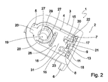
- Fig. 2 shows a perspective view of the embodiment of a plug nut 1 according to the invention Fig. 1 with a view of the sliding part 16 facing away from the cover plate 3 of the bearing part 2.
- Fig. 2 is clearly in the lateral direction double-sided rear grip of the sliding webs 17, 18 by the edge rails 7, 8 and inner rails 9, 10 can be seen.
- the illustration according to Fig. 2 can be seen that at the cover plate 3 facing the end of the screw receiving channel 19 radially inwardly projecting engagement projections 27 are formed to engage with an in Fig. 2 To promote fastening screw, not shown. Furthermore, it is off Fig.
- curved mounting bevels 28, 29 are formed on both sides of the screw receiving channel 19, which increase from its side facing the mounting tongue 20 in the direction of the sliding webs 17, 18 side facing the cover plate 3 of the bearing part 2 toward and thus as the mounting tongue 20 to facilitate the assembly of the socket nut 1 serve.
- Fig. 3 shows in a sectional view of the embodiment of a plug nut according to the invention according to Fig. 1 and Fig. 2 , here in the variant according to Fig. 2 in a mounting arrangement for attaching an attachment 32 to a relatively thin support member 33.
- the socket nut 1 rests with the cover plate 3 of the bearing part 2 on a side facing the attachment 32 side of the support member 33, wherein the edge plate 6 bears against a Suteilausströmung 34 opposite edge side ,
- Fig. 4 shows in a sectional view of the basic arrangement according to Fig. 3 with one opposite the in Fig. 3 shown support member 33 considerably larger thickness.
- the spring arm 11 is now bent away from the edge plate 6 of the bearing part 2 and, as in the arrangement according to Fig. 4 in the present case, with a maximum permissible thickness of the carrier part 33 with the transverse web 14 strikes against the abutment member 16 formed as an end stop stop structure 26 to avoid overloading with a plastic deformation or even with a fracture of the spring arm 11.
Abstract
Description
Die Erfindung betrifft eine Steckmutter gemäß dem Oberbegriff des Patentanspruches 1.The invention relates to a socket nut according to the preamble of claim 1.
Eine derartige Steckmutter ist aus
Der Erfindung liegt die Aufgabe zugrunde, eine Steckmutter der eingangs genannten Art anzugeben, die sich durch eine verhältnismäßig einfache Herstellung und eine gute Stabilität auszeichnet.The invention has for its object to provide a socket nut of the type mentioned, which is characterized by a relatively simple production and good stability.
Diese Aufgabe wird bei einer Steckmutter der eingangs genannten Art erfindungsgemäß mit den kennzeichnenden Merkmalen des Patentanspruches 1 gelöst.This object is achieved according to the invention with the characterizing features of claim 1 in a socket nut of the type mentioned.
Dadurch, dass bei der erfindungsgemäßen Steckmutter die Federanordnung wenigstens einen Federarm aufweist, dessen Betätigungsende gegenüber dem Verschiebeteil frei beweglich gelagert ist, lassen sich das Lagerteil und das Verschiebeteil verhältnismäßig einfach werkzeugtechnisch getrennt voneinander herstellen und nachträglich montieren oder in einem Werkzeug beispielsweise mittels einer Filmanbindung gemeinsam herstellen und noch vor dem Auswurf im Werkzeug vorzugsweise verliersicher zusammenfügen. Weiterhin lässt sich der oder jeder Federarm zum Erzielen einer hohen Stabilität verhältnismäßig massiv ausbilden, wobei bei einem entsprechenden Einrichten der Lagerung des Betätigungsendes des Federarmes auch bei einem verhältnismäßig kräftig ausgebildeten Federarm dennoch ein einfaches Anbringen fördernde, relativ geringe Vorspannkräfte vorhanden sind.Due to the fact that, in the inventive plug-in nut, the spring arrangement has at least one spring arm whose actuating end is mounted so as to be freely movable relative to the sliding part, the bearing part and the sliding part can be manufactured relatively simply from one another and from one another technically mount later or together in a tool, for example by means of a Filmanbindung and preferably before the ejection in the tool put together captive. Furthermore, the or each spring arm to form a high stability can be relatively massive, with a corresponding setting up the storage of the operating end of the spring arm even with a relatively strong trained spring arm still a simple attachment promotional, relatively low biasing forces are present.
Weitere zweckmäßige Ausgestaltungen der Erfindung sind Gegenstand der Unteransprüche.Further expedient embodiments of the invention are the subject of the dependent claims.
Weitere zweckmäßige Ausgestaltungen und Vorteile der Erfindung ergeben sich aus der nachfolgenden Beschreibung eines Ausführungsbeispieles mit Bezug auf die Figuren der Zeichnung. Es zeigen:
- Fig. 1
- in einer perspektivischen Ansicht ein Ausführungsbeispiel einer erfindungsgemäßen Steckmutter mit Blick auf die einem Verschiebeteil zugewandte Seite einer Deckplatte eines Lagerteiles,
- Fig. 2
- in einer perspektivischen Ansicht das Ausführungsbeispiel gemäß
Fig. 1 mit Blick auf die dem Verschiebeteil abgewandte Seite der Deckplatte, - Fig. 3
- in einer Schnittansicht das Ausführungsbeispiel gemäß
Fig. 1 undFig. 2 in einer Vormontageanordnung beim Verbinden eines Anbauteiles mit einem relativ dünnen Trägerteil und - Fig. 4
- in einer Schnittansicht das Ausführungsbeispiel gemäß
Fig. 1 undFig. 2 in einer Vormontageanordnung beim Verbinden eines Anbauteiles mit einem relativ dicken Trägerteil.
- Fig. 1
- in a perspective view of an embodiment of a plug nut according to the invention with a view of a sliding part facing side of a cover plate of a bearing part,
- Fig. 2
- in a perspective view of the embodiment according to
Fig. 1 with a view of the side of the cover plate facing away from the sliding part, - Fig. 3
- in a sectional view of the embodiment according to
Fig. 1 andFig. 2 in a pre-assembly when connecting an attachment with a relatively thin support member and - Fig. 4
- in a sectional view of the embodiment according to
Fig. 1 andFig. 2 in a pre-assembly when joining an attachment with a relatively thick support member.
Auf der der Deckplattenfreimachung 5 gegenüberliegenden Seite ist die Deckplatte 3 mit einer Randplatte 6 verbunden, die bei diesem Ausführungsbeispiel rechtwinklig zu der Deckplatte 3 ausgerichtet ist und sich von der Deckplatte 3 einseitig weg erstreckt, so dass sich für das Lagerteil 2 eine L-artige Gestalt ergibt. Die Randplatte 6 weist auf ihrer der Deckplatte 3 zugewandten Seite eine Führungsanordnung auf, die bei diesem Ausführungsbeispiel durch eine erste Randschiene 7, eine zweite Randschiene 8, die außenseitig angeordnet sind, sowie durch eine erste Innenschiene 9 und eine zweite Innenschiene 10 gebildet ist, die innenseitig der Randschienen 7, 8 angeordnet sind. Die Innenschienen 9, 10 weisen einen Abstand voneinander auf. Die Randschienen 7, 8 und die Innenschienen 9, 10 sind parallel zueinander ausgerichtet und erstrecken sich in einer Längsrichtung der Randplatte 6 von dem der Deckplatte 3 zugewandten Ende bis zu dem der Deckplatte 3 abgewandten Ende der Randplatte 6.On the cover plate facing the
Weiterhin verfügt das Ausführungsbeispiel gemäß
Weiterhin verfügt die Steckmutter 1 gemäß dem Ausführungsbeispiel gemäß
Auf der den Gleitstegen 17, 18 abgewandten Seite ist das Verschiebeteil 16 mit einem sich in Längsrichtung erstreckenden Schraubenaufnahmekanal 19 ausgebildet, der sich durch die kürzere Seite des Verschiebeteiles 16 hindurch erstreckt. Weiterhin lässt sich der Darstellung gemäß
Zwischen den Gleitstegen 17, 18 und dem Schraubenaufnahmekanal 19 ist das Verschiebeteil 16 mit einem Federarmaufnahmeraum 21 ausgebildet, in den in der zusammengebauten Anordnung der Steckmutter 1 gemäß
Zum Erleichtern des Zusammenbaus der Steckmutter 1 sind die Gegensockel 25 an ihren den Federarmhaltesockeln 22, 23 abgewandten Außenseiten gekrümmt ausgebildet, so dass bei Einführen der Gleitstege 17, 18 zwischen die Randschienen 7, 8 und Innenschienen 9, 10 beginnend von der der Deckplatte 3 abgewandten Seite die Lagerenden 15 an den gekrümmten Außenseiten der Gegensockel 25 unter Verbiegen des Federarmes 11 aufgleiten und nach Eintritt in den Federarmaufnahmeraum 21 aufgrund der Vorspannung des Federarmes 11 direkt zwischen die Federarmhaltesockel 22, 23 und die Gegensockel 25 einschnappen. Auf der den Federarmhaltesockeln 22, 23 und den Gegensockeln 25 gegenüberliegenden Seite des Federarmaufnahmeraumes 21 ist eine Anschlagstruktur 26 ausgebildet, die in axialer Richtung gegenüber den Federarmhaltesockeln 22, 23 zu dem Anbindungsende 12 des Federarms 11 hin versetzt ist.To facilitate assembly of the plug-in nut 1, the
Weiterhin lässt sich der Darstellung gemäß
Zum Einnehmen der Anordnung gemäß
Aufgrund der verhältnismäßig geringen Dicke des in
Aus
Claims (7)
Applications Claiming Priority (1)
| Application Number | Priority Date | Filing Date | Title |
|---|---|---|---|
| DE102012207142A DE102012207142A1 (en) | 2012-04-27 | 2012-04-27 | Tube nut |
Publications (3)
| Publication Number | Publication Date |
|---|---|
| EP2657549A2 true EP2657549A2 (en) | 2013-10-30 |
| EP2657549A3 EP2657549A3 (en) | 2016-08-24 |
| EP2657549B1 EP2657549B1 (en) | 2019-11-13 |
Family
ID=48047895
Family Applications (1)
| Application Number | Title | Priority Date | Filing Date |
|---|---|---|---|
| EP13162729.1A Active EP2657549B1 (en) | 2012-04-27 | 2013-04-08 | Push-on nut |
Country Status (2)
| Country | Link |
|---|---|
| EP (1) | EP2657549B1 (en) |
| DE (1) | DE102012207142A1 (en) |
Cited By (1)
| Publication number | Priority date | Publication date | Assignee | Title |
|---|---|---|---|---|
| US11773895B2 (en) | 2019-05-01 | 2023-10-03 | Erico International Corporation | Spring nut with release |
Families Citing this family (1)
| Publication number | Priority date | Publication date | Assignee | Title |
|---|---|---|---|---|
| EP3126685B1 (en) | 2014-03-31 | 2021-02-17 | Böllhoff Verbindungstechnik GmbH | Connector, connecting method and a production method for same |
Citations (1)
| Publication number | Priority date | Publication date | Assignee | Title |
|---|---|---|---|---|
| EP1784578B1 (en) | 2004-09-02 | 2008-03-19 | EJOT GmbH & Co. KG | U-shaped clamp |
Family Cites Families (2)
| Publication number | Priority date | Publication date | Assignee | Title |
|---|---|---|---|---|
| NL249244A (en) * | 1959-03-09 | |||
| US3145753A (en) * | 1961-01-24 | 1964-08-25 | Frederick W Rohe | Spring clip and nut assembly |
-
2012
- 2012-04-27 DE DE102012207142A patent/DE102012207142A1/en not_active Ceased
-
2013
- 2013-04-08 EP EP13162729.1A patent/EP2657549B1/en active Active
Patent Citations (1)
| Publication number | Priority date | Publication date | Assignee | Title |
|---|---|---|---|---|
| EP1784578B1 (en) | 2004-09-02 | 2008-03-19 | EJOT GmbH & Co. KG | U-shaped clamp |
Cited By (1)
| Publication number | Priority date | Publication date | Assignee | Title |
|---|---|---|---|---|
| US11773895B2 (en) | 2019-05-01 | 2023-10-03 | Erico International Corporation | Spring nut with release |
Also Published As
| Publication number | Publication date |
|---|---|
| DE102012207142A1 (en) | 2013-10-31 |
| EP2657549B1 (en) | 2019-11-13 |
| EP2657549A3 (en) | 2016-08-24 |
Similar Documents
| Publication | Publication Date | Title |
|---|---|---|
| EP2605936B1 (en) | Device for holding an add-on part on a support part, and arrangement with a device of this type and with an add-on part | |
| EP2786447B1 (en) | Connecting terminal with a web-shaped conductor guide | |
| EP2536958B1 (en) | Fastening device | |
| EP2601418B1 (en) | Expanding rivet | |
| EP2193277A1 (en) | Device for securing an add-on to a support | |
| DE102009024983A1 (en) | joint assembly | |
| WO2005059380A1 (en) | Device for connecting a support element to an add-on piece | |
| DE102011017154A1 (en) | Speed nut | |
| EP2198170B1 (en) | Device for fixing an attachment to a supporting part | |
| EP2657549B1 (en) | Push-on nut | |
| DE102004054689A1 (en) | fastening device | |
| EP2651709B1 (en) | Wiper blade device | |
| EP2651712B1 (en) | Wiper blade device | |
| EP2512866B1 (en) | Device for fastening an object in a recess | |
| EP2067906B1 (en) | Connection system for trough shaped profile bars and connection arrangement | |
| DE102014117287A1 (en) | unit | |
| EP2507880B1 (en) | Fastening device | |
| EP2651708B1 (en) | Wiper blade device | |
| EP2651716B1 (en) | Wiperblade | |
| DE102010039454A1 (en) | Closure for fastening device of surface element of fume extraction hood, has base with inlet opening for snap-in element and closure portion above base, where closure portion consists of two shanks connected with base and connecting bar | |
| DE102011010141A1 (en) | Fastening device for connecting attachment unit to support unit in airbag assembly, has inner wing and outer wing that are provided in two shaft arms that are connected to the cover plate | |
| EP2568215A2 (en) | Light strip | |
| DE2064130C (en) | Fastening of metallic rails to insulating parts, especially for electrical distribution and terminal strips | |
| DE102014115639A1 (en) | Door seal system | |
| DE102015119244A1 (en) | Arrangement of a lens on a lens holder |
Legal Events
| Date | Code | Title | Description |
|---|---|---|---|
| PUAI | Public reference made under article 153(3) epc to a published international application that has entered the european phase |
Free format text: ORIGINAL CODE: 0009012 |
|
| AK | Designated contracting states |
Kind code of ref document: A2 Designated state(s): AL AT BE BG CH CY CZ DE DK EE ES FI FR GB GR HR HU IE IS IT LI LT LU LV MC MK MT NL NO PL PT RO RS SE SI SK SM TR |
|
| AX | Request for extension of the european patent |
Extension state: BA ME |
|
| RAP1 | Party data changed (applicant data changed or rights of an application transferred) |
Owner name: A. RAYMOND ET CIE |
|
| PUAL | Search report despatched |
Free format text: ORIGINAL CODE: 0009013 |
|
| AK | Designated contracting states |
Kind code of ref document: A3 Designated state(s): AL AT BE BG CH CY CZ DE DK EE ES FI FR GB GR HR HU IE IS IT LI LT LU LV MC MK MT NL NO PL PT RO RS SE SI SK SM TR |
|
| AX | Request for extension of the european patent |
Extension state: BA ME |
|
| RIC1 | Information provided on ipc code assigned before grant |
Ipc: F16B 37/04 20060101AFI20160715BHEP |
|
| STAA | Information on the status of an ep patent application or granted ep patent |
Free format text: STATUS: REQUEST FOR EXAMINATION WAS MADE |
|
| 17P | Request for examination filed |
Effective date: 20170222 |
|
| RBV | Designated contracting states (corrected) |
Designated state(s): AL AT BE BG CH CY CZ DE DK EE ES FI FR GB GR HR HU IE IS IT LI LT LU LV MC MK MT NL NO PL PT RO RS SE SI SK SM TR |
|
| STAA | Information on the status of an ep patent application or granted ep patent |
Free format text: STATUS: EXAMINATION IS IN PROGRESS |
|
| 17Q | First examination report despatched |
Effective date: 20181025 |
|
| GRAP | Despatch of communication of intention to grant a patent |
Free format text: ORIGINAL CODE: EPIDOSNIGR1 |
|
| STAA | Information on the status of an ep patent application or granted ep patent |
Free format text: STATUS: GRANT OF PATENT IS INTENDED |
|
| INTG | Intention to grant announced |
Effective date: 20190529 |
|
| GRAS | Grant fee paid |
Free format text: ORIGINAL CODE: EPIDOSNIGR3 |
|
| GRAA | (expected) grant |
Free format text: ORIGINAL CODE: 0009210 |
|
| STAA | Information on the status of an ep patent application or granted ep patent |
Free format text: STATUS: THE PATENT HAS BEEN GRANTED |
|
| AK | Designated contracting states |
Kind code of ref document: B1 Designated state(s): AL AT BE BG CH CY CZ DE DK EE ES FI FR GB GR HR HU IE IS IT LI LT LU LV MC MK MT NL NO PL PT RO RS SE SI SK SM TR |
|
| REG | Reference to a national code |
Ref country code: CH Ref legal event code: EP Ref country code: AT Ref legal event code: REF Ref document number: 1201957 Country of ref document: AT Kind code of ref document: T Effective date: 20191115 |
|
| REG | Reference to a national code |
Ref country code: DE Ref legal event code: R096 Ref document number: 502013013883 Country of ref document: DE |
|
| REG | Reference to a national code |
Ref country code: IE Ref legal event code: FG4D Free format text: LANGUAGE OF EP DOCUMENT: GERMAN |
|
| REG | Reference to a national code |
Ref country code: NL Ref legal event code: MP Effective date: 20191113 |
|
| REG | Reference to a national code |
Ref country code: LT Ref legal event code: MG4D |
|
| PG25 | Lapsed in a contracting state [announced via postgrant information from national office to epo] |
Ref country code: NL Free format text: LAPSE BECAUSE OF FAILURE TO SUBMIT A TRANSLATION OF THE DESCRIPTION OR TO PAY THE FEE WITHIN THE PRESCRIBED TIME-LIMIT Effective date: 20191113 Ref country code: LT Free format text: LAPSE BECAUSE OF FAILURE TO SUBMIT A TRANSLATION OF THE DESCRIPTION OR TO PAY THE FEE WITHIN THE PRESCRIBED TIME-LIMIT Effective date: 20191113 Ref country code: GR Free format text: LAPSE BECAUSE OF FAILURE TO SUBMIT A TRANSLATION OF THE DESCRIPTION OR TO PAY THE FEE WITHIN THE PRESCRIBED TIME-LIMIT Effective date: 20200214 Ref country code: PL Free format text: LAPSE BECAUSE OF FAILURE TO SUBMIT A TRANSLATION OF THE DESCRIPTION OR TO PAY THE FEE WITHIN THE PRESCRIBED TIME-LIMIT Effective date: 20191113 Ref country code: ES Free format text: LAPSE BECAUSE OF FAILURE TO SUBMIT A TRANSLATION OF THE DESCRIPTION OR TO PAY THE FEE WITHIN THE PRESCRIBED TIME-LIMIT Effective date: 20191113 Ref country code: PT Free format text: LAPSE BECAUSE OF FAILURE TO SUBMIT A TRANSLATION OF THE DESCRIPTION OR TO PAY THE FEE WITHIN THE PRESCRIBED TIME-LIMIT Effective date: 20200313 Ref country code: FI Free format text: LAPSE BECAUSE OF FAILURE TO SUBMIT A TRANSLATION OF THE DESCRIPTION OR TO PAY THE FEE WITHIN THE PRESCRIBED TIME-LIMIT Effective date: 20191113 Ref country code: NO Free format text: LAPSE BECAUSE OF FAILURE TO SUBMIT A TRANSLATION OF THE DESCRIPTION OR TO PAY THE FEE WITHIN THE PRESCRIBED TIME-LIMIT Effective date: 20200213 Ref country code: BG Free format text: LAPSE BECAUSE OF FAILURE TO SUBMIT A TRANSLATION OF THE DESCRIPTION OR TO PAY THE FEE WITHIN THE PRESCRIBED TIME-LIMIT Effective date: 20200213 Ref country code: LV Free format text: LAPSE BECAUSE OF FAILURE TO SUBMIT A TRANSLATION OF THE DESCRIPTION OR TO PAY THE FEE WITHIN THE PRESCRIBED TIME-LIMIT Effective date: 20191113 Ref country code: SE Free format text: LAPSE BECAUSE OF FAILURE TO SUBMIT A TRANSLATION OF THE DESCRIPTION OR TO PAY THE FEE WITHIN THE PRESCRIBED TIME-LIMIT Effective date: 20191113 |
|
| PG25 | Lapsed in a contracting state [announced via postgrant information from national office to epo] |
Ref country code: HR Free format text: LAPSE BECAUSE OF FAILURE TO SUBMIT A TRANSLATION OF THE DESCRIPTION OR TO PAY THE FEE WITHIN THE PRESCRIBED TIME-LIMIT Effective date: 20191113 Ref country code: IS Free format text: LAPSE BECAUSE OF FAILURE TO SUBMIT A TRANSLATION OF THE DESCRIPTION OR TO PAY THE FEE WITHIN THE PRESCRIBED TIME-LIMIT Effective date: 20200313 Ref country code: RS Free format text: LAPSE BECAUSE OF FAILURE TO SUBMIT A TRANSLATION OF THE DESCRIPTION OR TO PAY THE FEE WITHIN THE PRESCRIBED TIME-LIMIT Effective date: 20191113 |
|
| PG25 | Lapsed in a contracting state [announced via postgrant information from national office to epo] |
Ref country code: AL Free format text: LAPSE BECAUSE OF FAILURE TO SUBMIT A TRANSLATION OF THE DESCRIPTION OR TO PAY THE FEE WITHIN THE PRESCRIBED TIME-LIMIT Effective date: 20191113 |
|
| PG25 | Lapsed in a contracting state [announced via postgrant information from national office to epo] |
Ref country code: EE Free format text: LAPSE BECAUSE OF FAILURE TO SUBMIT A TRANSLATION OF THE DESCRIPTION OR TO PAY THE FEE WITHIN THE PRESCRIBED TIME-LIMIT Effective date: 20191113 Ref country code: DK Free format text: LAPSE BECAUSE OF FAILURE TO SUBMIT A TRANSLATION OF THE DESCRIPTION OR TO PAY THE FEE WITHIN THE PRESCRIBED TIME-LIMIT Effective date: 20191113 Ref country code: RO Free format text: LAPSE BECAUSE OF FAILURE TO SUBMIT A TRANSLATION OF THE DESCRIPTION OR TO PAY THE FEE WITHIN THE PRESCRIBED TIME-LIMIT Effective date: 20191113 |
|
| REG | Reference to a national code |
Ref country code: DE Ref legal event code: R097 Ref document number: 502013013883 Country of ref document: DE |
|
| PG25 | Lapsed in a contracting state [announced via postgrant information from national office to epo] |
Ref country code: SK Free format text: LAPSE BECAUSE OF FAILURE TO SUBMIT A TRANSLATION OF THE DESCRIPTION OR TO PAY THE FEE WITHIN THE PRESCRIBED TIME-LIMIT Effective date: 20191113 Ref country code: SM Free format text: LAPSE BECAUSE OF FAILURE TO SUBMIT A TRANSLATION OF THE DESCRIPTION OR TO PAY THE FEE WITHIN THE PRESCRIBED TIME-LIMIT Effective date: 20191113 |
|
| PLBE | No opposition filed within time limit |
Free format text: ORIGINAL CODE: 0009261 |
|
| STAA | Information on the status of an ep patent application or granted ep patent |
Free format text: STATUS: NO OPPOSITION FILED WITHIN TIME LIMIT |
|
| 26N | No opposition filed |
Effective date: 20200814 |
|
| PG25 | Lapsed in a contracting state [announced via postgrant information from national office to epo] |
Ref country code: CZ Free format text: LAPSE BECAUSE OF FAILURE TO SUBMIT A TRANSLATION OF THE DESCRIPTION OR TO PAY THE FEE WITHIN THE PRESCRIBED TIME-LIMIT Effective date: 20191113 |
|
| REG | Reference to a national code |
Ref country code: DE Ref legal event code: R119 Ref document number: 502013013883 Country of ref document: DE |
|
| PG25 | Lapsed in a contracting state [announced via postgrant information from national office to epo] |
Ref country code: MC Free format text: LAPSE BECAUSE OF FAILURE TO SUBMIT A TRANSLATION OF THE DESCRIPTION OR TO PAY THE FEE WITHIN THE PRESCRIBED TIME-LIMIT Effective date: 20191113 Ref country code: SI Free format text: LAPSE BECAUSE OF FAILURE TO SUBMIT A TRANSLATION OF THE DESCRIPTION OR TO PAY THE FEE WITHIN THE PRESCRIBED TIME-LIMIT Effective date: 20191113 |
|
| REG | Reference to a national code |
Ref country code: CH Ref legal event code: PL |
|
| PG25 | Lapsed in a contracting state [announced via postgrant information from national office to epo] |
Ref country code: IT Free format text: LAPSE BECAUSE OF FAILURE TO SUBMIT A TRANSLATION OF THE DESCRIPTION OR TO PAY THE FEE WITHIN THE PRESCRIBED TIME-LIMIT Effective date: 20191113 Ref country code: LU Free format text: LAPSE BECAUSE OF NON-PAYMENT OF DUE FEES Effective date: 20200408 Ref country code: DE Free format text: LAPSE BECAUSE OF NON-PAYMENT OF DUE FEES Effective date: 20201103 Ref country code: CH Free format text: LAPSE BECAUSE OF NON-PAYMENT OF DUE FEES Effective date: 20200430 Ref country code: LI Free format text: LAPSE BECAUSE OF NON-PAYMENT OF DUE FEES Effective date: 20200430 Ref country code: FR Free format text: LAPSE BECAUSE OF NON-PAYMENT OF DUE FEES Effective date: 20200430 |
|
| REG | Reference to a national code |
Ref country code: BE Ref legal event code: MM Effective date: 20200430 |
|
| PG25 | Lapsed in a contracting state [announced via postgrant information from national office to epo] |
Ref country code: BE Free format text: LAPSE BECAUSE OF NON-PAYMENT OF DUE FEES Effective date: 20200430 |
|
| GBPC | Gb: european patent ceased through non-payment of renewal fee |
Effective date: 20200408 |
|
| PG25 | Lapsed in a contracting state [announced via postgrant information from national office to epo] |
Ref country code: GB Free format text: LAPSE BECAUSE OF NON-PAYMENT OF DUE FEES Effective date: 20200408 Ref country code: IE Free format text: LAPSE BECAUSE OF NON-PAYMENT OF DUE FEES Effective date: 20200408 |
|
| REG | Reference to a national code |
Ref country code: AT Ref legal event code: MM01 Ref document number: 1201957 Country of ref document: AT Kind code of ref document: T Effective date: 20200408 |
|
| PG25 | Lapsed in a contracting state [announced via postgrant information from national office to epo] |
Ref country code: AT Free format text: LAPSE BECAUSE OF NON-PAYMENT OF DUE FEES Effective date: 20200408 |
|
| PG25 | Lapsed in a contracting state [announced via postgrant information from national office to epo] |
Ref country code: TR Free format text: LAPSE BECAUSE OF FAILURE TO SUBMIT A TRANSLATION OF THE DESCRIPTION OR TO PAY THE FEE WITHIN THE PRESCRIBED TIME-LIMIT Effective date: 20191113 Ref country code: MT Free format text: LAPSE BECAUSE OF FAILURE TO SUBMIT A TRANSLATION OF THE DESCRIPTION OR TO PAY THE FEE WITHIN THE PRESCRIBED TIME-LIMIT Effective date: 20191113 Ref country code: CY Free format text: LAPSE BECAUSE OF FAILURE TO SUBMIT A TRANSLATION OF THE DESCRIPTION OR TO PAY THE FEE WITHIN THE PRESCRIBED TIME-LIMIT Effective date: 20191113 |
|
| PG25 | Lapsed in a contracting state [announced via postgrant information from national office to epo] |
Ref country code: MK Free format text: LAPSE BECAUSE OF FAILURE TO SUBMIT A TRANSLATION OF THE DESCRIPTION OR TO PAY THE FEE WITHIN THE PRESCRIBED TIME-LIMIT Effective date: 20191113 |