EP2657416A2 - Sanitary washing apparatus - Google Patents
Sanitary washing apparatus Download PDFInfo
- Publication number
- EP2657416A2 EP2657416A2 EP13164993.1A EP13164993A EP2657416A2 EP 2657416 A2 EP2657416 A2 EP 2657416A2 EP 13164993 A EP13164993 A EP 13164993A EP 2657416 A2 EP2657416 A2 EP 2657416A2
- Authority
- EP
- European Patent Office
- Prior art keywords
- electromagnetic valve
- pump
- water
- supply
- sanitary washing
- Prior art date
- Legal status (The legal status is an assumption and is not a legal conclusion. Google has not performed a legal analysis and makes no representation as to the accuracy of the status listed.)
- Withdrawn
Links
Images



Classifications
-
- E—FIXED CONSTRUCTIONS
- E03—WATER SUPPLY; SEWERAGE
- E03D—WATER-CLOSETS OR URINALS WITH FLUSHING DEVICES; FLUSHING VALVES THEREFOR
- E03D9/00—Sanitary or other accessories for lavatories ; Devices for cleaning or disinfecting the toilet room or the toilet bowl; Devices for eliminating smells
- E03D9/08—Devices in the bowl producing upwardly-directed sprays; Modifications of the bowl for use with such devices ; Bidets; Combinations of bowls with urinals or bidets; Hot-air or other devices mounted in or on the bowl, urinal or bidet for cleaning or disinfecting
Definitions
- This disclosure generally relates to a sanitary washing apparatus for washing a human private part.
- sanitary washing apparatuses There are two major types of known sanitary washing apparatuses provided at a warm water washing toilet seat and discharging warm water to wash a human private part in view of a method of supplying washing water.
- One of the two types refers to the sanitary washing apparatus where water that is supplied from a public water supply is heated directly (that is, without using a pump) and then used for washing.
- a water pressure of the public water supply is used as-is as a water pressure of the washing water.
- the other one of the two types refers to the sanitary washing apparatus where the water supplied from the public water supply is obtained via the pump, heated and then used as the washing water.
- the water supplied from the public water supply is stored at a water storage tank once, and the water stored at the water storage tank is pumped up by the pump and then used.
- the water pressure is applied by the pump to the washing water.
- the sanitary washing apparatus where the pump is applied is suitably used.
- the known sanitary washing apparatus As disclosed in JPS59-102030A and JPH3-20386Y (which are hereinafter referred to as Patent reference 1 and Patent reference 2, respectively), the known sanitary washing apparatus, where the pump is used for obtaining the water from the supply water source, includes a control circuit and/or a controller for controlling the pump.
- the sanitary washing apparatus connected directly to the water supply is not provided with the pump for obtaining the water from the supply water source, and therefore the aforementioned control circuit and/or the controller for controlling the pump do not need to be provided. Accordingly, in order to manufacture the known sanitary washing apparatus where the pump for obtaining the water from the supply water source is used, a control circuit and/or a controller need to be configured and arranged so as to be completely different from those of the sanitary washing apparatus which is connected directly to the water supply.
- a control means 51 controlling an opening/closing operation of an electromagnetic valve 48 via a first solid state relay (SSR) 50 additionally includes a function for controlling an operation of a pump motor 42a of a pump 42.
- SSR solid state relay
- control means 51 is connected via a second solid state relay (SSR) 44 which is supplied with electric power from a power supply 49 and is connected, for example, to the pump motor 42a.
- a water flow control portion 47 which includes the electromagnetic valve 48 and the first SSR 50, is commonly provided at the sanitary washing apparatus where the pump 42 is not used and at the sanitary washing apparatus where the pump 42 is used.
- an upstream side of a water flow path relative to the electromagnetic valve 48 is connected directly to the public water supply without the pump 42 interposed between the public water supply and the electromagnetic valve 48.
- a water pressure of water outputted from the pump 42 is adjusted by adjusting voltage of the pump motor 42a by means of a voltage adjustment circuit 46 for adjusting voltage of a driving power supply.
- a second control means 144 may be provided at a sanitary washing apparatus 141 independently from the first control means 51 controlling the electromagnetic valve 48 (the first control means 51 corresponds to the control means 51 in Fig. 5A ).
- the function of the control means of the sanitary washing apparatus that does not include the pump 42 needs to be modified to a large extent or the independent control means needs to be arranged.
- the control means for each of the types needs to be designed and manufactured independently from each other. This may result in an increase in manufacturing costs and an increase in the number of manufacturing processes.
- a sanitary washing apparatus includes a pump for delivering a washing water to a water flow route to which the washing water flows, an electromagnetic valve interposed between a supply water source and the pump, and allowing the washing water to be supplied from the supply water source, a control means for controlling the electromagnetic valve to open/close, and a switching circuit provided with a switching element, the switching circuit links an opening/closing operation of the electromagnetic valve and an operation/operation stop of the pump to each other without an interposition of the control means, the switching circuit operates the pump when the electromagnetic valve is in an open state in which the electromagnetic valve supplies the washing water and stops the pump when the electromagnetic valve is in a closed state in which the electromagnetic valve blocks supply of the washing water.
- an electric system and a water flow path of the electromagnetic valve, and an electric system and a water flow path of the pump are linked to or associated with each other by means of a function or an operation of the switching circuit that is provided with the switching element.
- the electromagnetic valve is commonly provided also at a type of the sanitary washing apparatus which is not provided with the pump and which is connected directly to the supply water source such as a public water system.
- the sanitary washing apparatus which has the above-described structure at which the pump is provided, is configured on the basis of a configuration of a type of the sanitary washing apparatus, which is not provided with the pump and which is connected directly to the supply water source, there is no need that the control means controlling the electromagnetic valve controls also the pump and there is no need to provide an independent control means that exclusively controls the pump.
- the sanitary washing apparatus provided with the pump may be configured without modifying the control means or increasing a number of the control means.
- the electromagnetic valve includes an opening/closing electric circuit where the electromagnetic valve is in the open state when the electromagnetic valve is electrified and the electromagnetic valve is in the closed state when the electromagnetic valve is not electrified
- the switching element includes a relay
- the relay includes an input terminal that is parallelly connected to the opening/closing electric circuit of the electromagnetic valve and an output terminal that is serially inserted in an intermediate portion of a driving power supply circuit of the pump, and an electric power from a driving power supply is supplied to the pump when the electromagnetic valve is in the open state by the opening/closing electric circuit and supply of the electric power to the pump is interrupted when the electromagnetic valve is in the closed state by the opening/closing electric circuit.
- the sanitary washing apparatus includes the switching circuits at which the switching element includes the relay, and each of the input terminal and the output terminal of the relay is connected between the electromagnetic valve and the pump as described above. Consequently, the opening/closing operation of the electromagnetic valve, and the operation and the operation stop of the pump are linked with each other with the simple configuration.
- the driving power supply circuit of the pump includes a voltage adjustment circuit configured to adjust an electric voltage supplied to the pump.
- a power supply for opening/closing the electromagnetic valve is commonly used for the driving power supply to the pump.
- a power supply for driving the pump is supplied via an AC adapter from a commercial power supply.
- the pump is driven or actuated even in a case where a capacity of the power supply for opening/closing the electromagnetic valve does not satisfy an electric current flow that is needed for driving the pump.
- the sanitary washing apparatus includes a water storage tank for reducing a pressure of the washing water from the supply water source, wherein the washing water is stored at the water storage tank by the opening/closing operation of the electromagnetic valve and the washing water stored at the water storage tank is delivered by the pump to the water flow route.
- Fig. 1A is a diagram schematically illustrating an electrical system and a water flow path of a configuration of a sanitary washing apparatus according to a first embodiment disclosed here;
- Fig. 1B is a diagram schematically illustrating an electrical system and a water flow path of a configuration of a sanitary washing apparatus that is directly connected to a water supply;
- Fig. 2 is a diagram schematically illustrating an electrical system and a water flow path of a sanitary washing apparatus according to a second embodiment disclosed here;
- Fig. 3 is a block diagram illustrating a configuration of the water flow path according to the first embodiment
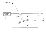
- Fig. 4 is a circuit diagram illustrating a configuration of a voltage adjustment circuit that is illustrated in Figs. 1A and 2 ;
- Fig. 5A is a diagram schematically illustrating a form of an electrical system and a water flow path of a known sanitary washing apparatus
- Fig. 5B is a diagram schematically illustrating another form of an electrical system and a water flow path of a known sanitary washing apparatus.
- a sanitary washing apparatus 1 includes a pump 2 for delivering water obtained from a supply water source S including, for example, a public water supply, to a water flow route R to which washing water flows.
- the water flow route R is the route to which the washing water flows and which includes a washing means such as, for example, a nozzle for washing a human private part and/or a discharging portion of water for washing a toilet bowl.
- the sanitary washing apparatus 1 includes a pump control unit 4 that is constituted by a relay 5 (i.e., a switching element) and by a voltage adjustment circuit 6. Further, the sanitary washing apparatus 1 includes a water flow control portion 7 provided with an electromagnetic valve 8. The electromagnetic valve 8 is arranged between the supply water source S and the pump 2, and controls supply of the washing water from the supply water source S.
- the pump 2 may be a pump which delivers or supplies the water of the supply water source S via the electromagnetic valve 8 directly to the water flow route R.
- the water may be stored at a water storage tank 3 once, and the water stored at the water storage tank 3 may be pumped up and then be delivered to the water flow route R.
- the pump control unit 4, and an electrical wiring which connects among the pump control unit 4, a pump motor 2a of the pump 2 and the water flow control portion 7 function as a switching circuit and play a role of linking an operation of the electromagnetic valve 8 and an operation of the pump 2.
- the water flow control portion 7 may be applied to a sanitary washing apparatus 31 as-is without making, for example, a modification.
- the sanitary washing apparatus 31 is a type of the sanitary washing apparatus which is not provided with the water storage tank 3 or the pump 2, and at which the electromagnetic valve 8 is connected directly to the water supply.
- a configuration and a function of the water flow control portion 7 will be explained on the basis of a configuration of the sanitary washing apparatus 31 of Fig. 1B .
- the water flow control portion 7 includes a power supply 9, a solid state relay (SSR) 10 and a control means 11, in addition to the electromagnetic valve 8. Electric power is drawn via an adapter 12 and is supplied to the power supply 9.
- SSR solid state relay
- the electromagnetic valve 8 is in an open state only while electric current having a voltage that is equal to or greater than a predetermined voltage value is being supplied to the electromagnetic valve 8, and is in a closed state when electric current is not supplied thereto, that is, the electromagnetic valve 8 is in the closed state when the electromagnetic valve 8 is not electrified.
- the electromagnetic valve 8 is a so-called normally closed-type electromagnetic valve.
- an upstream side of a water flow path relative to the electromagnetic valve 8 is connected to the supply water source S.
- a downstream side of the water flow path relative to the electromagnetic valve 8 is connected to the water flow route R so that the washing water is supplied via the electromagnetic valve 8 to the water flow route R.
- a warm water tank for temporarily storing the warm water may be provided between the electromagnetic valve 8 and the nozzle.
- the SSR 10 is inserted in an intermediate portion of an electric current supply circuit (i.e., an opening/closing electric circuit) connecting the power supply 9 and the electromagnetic valve 8 to each other.
- the SSR 10 is connected to the control means 11 so that an opening/closing operation of the electromagnetic valve 8 is controlled via the SSR 10 by the control means 11.
- the SSR 10 disconnects the electric current supply circuit so as to maintain the electromagnetic valve 8 in the closes state.
- a weak electric current is inputted from the control means 11 to the SSR 10, and the electric current supply circuit is connected via the SSR 10, that is, the electric current supply circuit is established. That is, the electric current is supplied from the power supply 9 to the electromagnetic valve 8, the electromagnetic valve 8 comes to be in the open state and the washing water is actually supplied to the water flow route R.
- the control means 11 is implemented by a microcomputer (a micon), for example.
- the control means 11 may have a function to perform not only the opening/closing operation of the electromagnetic valve 8 but also various controls that are needed at the sanitary washing apparatus, including, for example, a temperature adjustment of the washing water. Electric power necessary for operating the control means 11 may be supplied from the power supply 9.
- the washing water is delivered from the supply water source S via the electromagnetic valve 8 by means of the pump 2 to the water flow route R, but not from the supply water source S directly to the water flow route R.
- the switching circuit including the pump control unit 4 is connected to the water flow control portion 7, the configuration of the water flow control portion 7 including the electromagnetic valve 8 is identical to the configuration illustrated in the aforementioned Fig. 1B .
- Fig. 3 simply illustrates the water flow path of the sanitary washing apparatus 1 according to this embodiment.
- the water obtained from the supply water source S is delivered via the electromagnetic valve 8 to the water storage tank 3 and stored thereat once, and then is supplied by means of the pump 2 to the water flow route R including, for example, the nozzle for washing the human private part.
- the water storage tank 3 serves as an air gap which is provided with an air layer and reduces the pressure of the water obtained via the electromagnetic valve 8 from the supply water source S. Consequently, other configuration, which serves as the air gap, than the water storage tank 3 may be used as long as the function of the air gap is performed.
- the pump 2 pumps up the water of the water storage tank 3 as the pump motor 2a is driven to rotate or operate.
- a driving power supply for driving the pump motor 2a is drawn or obtained from the power supply 9 of the water flow control portion 7, that is, the power supply 9 provides the power supply for opening/closing the electromagnetic valve 8 and the power supply for driving the pump motor 2a.
- the power supply 9 for opening/closing the electromagnetic valve 8 is commonly used for the driving power supply to the pump 2.
- the relay 5 includes an input terminal 5a and an output terminal 5b.
- An input-side terminal of the relay 5, that is, the input terminal 5a, included in the pump control unit 4 is connected to the electric current supply circuit which connects the power supply 9 and the electromagnetic valve 8 to each other in a manner that the input-side terminal 5a of the relay 5 is parallel with the electromagnetic valve 8.
- An output-side of the relay 5, that is, the output terminal 5b, is serially inserted in an intermediate portion of a circuit connecting the pump motor 2a and the power supply 9 to each other (i.e., a driving power supply circuit of the pump). Further, the voltage adjustment circuit 6 is inserted between the power supply 9 and the pump motor 2a. A configuration and a function of the voltage adjustment circuit 6 will be explained later.
- the electromagnetic valve 8 In a state where the circuit between the power supply 9 and the electromagnetic valve 8 is blocked or disconnected by the SSR 10, the electromagnetic valve 8 is closed, the electric current is not supplied to the input-side of the relay 5 and the output-side of the relay 5 is opened. Because an electric current for driving the pump motor 2a is not supplied to the pump motor 2a, the pump motor 2a is in a state where the pump motor 2a is stopped. That is, the water flow path from the supply water source S toward the pump 2 is in interrupted by the electromagnetic valve 8, and accordingly the pump 2 is in a state where the operation is stopped.
- an electric system needed for opening/closing the electromagnetic valve 8 and an electric system needed for actuating/stopping the pump motor 2a are linked to or associated with each other by means of the relay 5, and supply/block of the water flow from the supply water source S toward the water flow route R is also linked with the opening/closing operation of the electromagnetic valve 8 and with the actuating/stopping the pump motor 2a.
- the sanitary washing apparatus 1 of this embodiment includes the water flow control portion 7 that may be commonly used for the sanitary washing apparatus 1 and for the sanitary washing apparatus 31 (which is the type of the sanitary washing apparatus where the pump 2 is not used as illustrated in Fig. 1B ), and the sanitary washing apparatus 1 of this embodiment may be configured simply by connecting the input side and the output side of the relay 5 of the pump control unit 4 to the respective portions as described above.
- the sanitary washing apparatus is allowed to be connected directly to the public water supply in a manner that the water pressure of the public water supply is used as-is as the water pressure of the washing water depends on legal regulations of countries and/or regions where the sanitary washing apparatus is used.
- the manufacturing costs and the number of the manufacturing processes are reduced largely by manufacturing both the sanitary washing apparatuses 1 and 31 by commonly applying the water flow control portion 7 to the sanitary washing apparatuses 1 and 31, and by differentiating between the sanitary washing apparatuses 1 and 31 only by whether or not the switching circuit including the pump control unit 4 is optionally provided at the sanitary washing machine.
- the link between the operation of the electromagnetic valve 8 and the operation of the pump motor 2a is established by the relay 5, however, it is not limited to the relay. Any switching element other than the relay may be used as long as the switching element causes the operations of the electromagnetic valve 8 and the pump motor 2a to be linked to or associated with each other without the interposition of the control means so that the pump motor 2a operates automatically when the electromagnetic valve 8 is in the open state.
- the switching elements other than the relay include a transistor.
- any types of relay including, for example, a contact relay and a noncontact relay, may be used.
- the voltage adjustment circuit 6 that is inserted in an intermediate portion of a power supply circuit to the pump motor 2a will be explained.
- the pump motor 2a that is commercially available includes a large variation in an output thereof among individuals, which causes variation in the water pressure of the washing water supplied via the electromagnetic valve 8 to the water flow route R. This causes variation in the water pressure of water supplied from the water flow route R to a user of the sanitary washing apparatus.
- the sanitary washing apparatus is provided with the washing means where the water flow route R includes the nozzle which discharges the warm water and which is configured to be extended by the water pressure of the washing water to an operable position, the nozzle may not be extended sufficiently if the water pressure of the washing water is too low.
- the water flow route R is provided with the warm water tank for temporarily storing the warm water and when the water pressure of the washing water supplied via the electromagnetic valve 8 is too high, a pressure applied to the warm water tank increases, and as a result, a large load may be applied to the warm water tank.
- the water pressure of the water that is outputted from the pump 2 may be adjusted by adjusting a voltage, that is, an electric voltage, of the driving power supply for driving the pump motor 2a.
- the adjustment of the voltage of the power supply for driving the pump motor 2a is performed by means of the voltage adjustment circuit 6.
- a known voltage adjustment circuit (a constant-voltage circuit) may be used.
- the voltage adjustment circuit 6 illustrated in Fig. 4 where a zener diode ZD, a transistor Tr and a variable resistor VR are used, may be applied.
- An electric current that is inputted from a DC power supply 61 (corresponding to the power supply 9 of the sanitary washing apparatus 1 of Fig. 1A ) is converted to an electric current having a voltage equal to or smaller than the electric voltage of the electric current inputted from the DC power supply 61.
- An output side of the voltage adjustment circuit 6 is connected to an input terminal of the pump motor 2a.
- an output voltage may be varied by varying a resistance value of the variable resistor VR.
- the resistance value of the variable resistor VR may be varied or changed while measuring the water pressure outputted from the pump, for each pump 2.
- a fixed resistor having a fixed resistance value may be inserted at the voltage adjustment circuit 6 instead of the variable resistor VR.
- the pump motor 2a is protected against an overvoltage without an overvoltage protection circuit that is additionally provided at the pump control unit 4 including the voltage adjustment circuit 6.
- a known overvoltage protection circuit may be further provided in the pump control unit 4.
- the power supply that is needed to actuate the pump motor 2a is drawn from the power supply 9 that is used for opening and closing the electromagnetic valve 8.
- a capacity of the power supply 9 is sufficient to provide an electric power that is needed to actuate the pump motor 2a
- the above-described configuration is appropriate from a point of view of simplicity and convenience.
- a configuration of a second embodiment may be applied, where a power supply for driving the pump is additionally provided. The second embodiment will be described hereunder.
- the configuration of a sanitary washing apparatus 21 according to the second embodiment is illustrated in Fig. 2 .
- the configuration of the sanitary washing apparatus 21 according to the second embodiment differs from the configuration of the sanitary washing apparatus 1 according to the first embodiment illustrated in Fig. 1A only in that the power supply for driving the pump motor 2a is supplied from a commercial power supply via an AC adapter 29 and a power plug 29a, each of which is independent from the power supply 9, instead of being supplied from the power supply 9 of the water flow control portion 7.
- Other configuration of the sanitary washing apparatus 21 is identical to that of the sanitary washing apparatus 1 according to the first embodiment, and therefore, in the drawing, the identical reference numerals are given to structural elements corresponding to those of the first embodiment.
- the pump motor 2a is actuated even in a case where the capacity of the power supply 9 is not sufficient to provide the electric power needed for actuating the pump motor 2a because, for example, the output of the pump 2 is large.
- the output side of the relay 5 is inserted at an electric path through which an output from the AC adapter 29 is inputted to the pump motor 2a. Accordingly, only when the electromagnetic valve 8 is in the open state, the power supply is provided from the AC adapter 29 to the pump motor 2a and the pump motor 2a operates so that the water of the water storage tank 3 is supplied to the water flow route R.
- the embodiments disclosed here are not limited to the configurations described in detail above. Various changes and modifications may be made without departing from the spirit and scope of this disclosure.
- the voltage adjustment circuit need not be provided depending on the specifications of the pump motor. Further, in a case where the voltage adjustment circuit is provided, the configuration thereof is not limited to that illustrated in Fig. 4 .
- the configuration of the pump control unit, and a method of linking between the respective operations of the electromagnetic valve and the pump are applicable to any apparatus, where water is obtained from a supply water source by using a pump, other than the sanitary washing apparatus for washing the human private part and/or for washing the toilet bowl.
- the positions at which the respective pump and the electromagnetic valve are arranged are not limited to those described above.
Landscapes
- Health & Medical Sciences (AREA)
- Public Health (AREA)
- Molecular Biology (AREA)
- Epidemiology (AREA)
- Life Sciences & Earth Sciences (AREA)
- Engineering & Computer Science (AREA)
- Hydrology & Water Resources (AREA)
- Water Supply & Treatment (AREA)
- Bidet-Like Cleaning Device And Other Flush Toilet Accessories (AREA)
Abstract
Description
- This disclosure generally relates to a sanitary washing apparatus for washing a human private part.
- There are two major types of known sanitary washing apparatuses provided at a warm water washing toilet seat and discharging warm water to wash a human private part in view of a method of supplying washing water. One of the two types refers to the sanitary washing apparatus where water that is supplied from a public water supply is heated directly (that is, without using a pump) and then used for washing. In this type, a water pressure of the public water supply is used as-is as a water pressure of the washing water. The other one of the two types refers to the sanitary washing apparatus where the water supplied from the public water supply is obtained via the pump, heated and then used as the washing water. In some cases, the water supplied from the public water supply is stored at a water storage tank once, and the water stored at the water storage tank is pumped up by the pump and then used. In this type where the water is obtained from a supply water source by using the pump, the water pressure is applied by the pump to the washing water. In a case where it is not allowed to connect the sanitary washing apparatus directly to the public water supply and to use the water pressure of the public water supply for reasons of, for example, legal regulations, the sanitary washing apparatus where the pump is applied is suitably used.
- As disclosed in JPS59-102030A and JPH3-20386Y (which are hereinafter referred to as
Patent reference 1 andPatent reference 2, respectively), the known sanitary washing apparatus, where the pump is used for obtaining the water from the supply water source, includes a control circuit and/or a controller for controlling the pump. - However, the sanitary washing apparatus connected directly to the water supply is not provided with the pump for obtaining the water from the supply water source, and therefore the aforementioned control circuit and/or the controller for controlling the pump do not need to be provided. Accordingly, in order to manufacture the known sanitary washing apparatus where the pump for obtaining the water from the supply water source is used, a control circuit and/or a controller need to be configured and arranged so as to be completely different from those of the sanitary washing apparatus which is connected directly to the water supply.
- One known case where the sanitary washing apparatus, at which the pump for obtaining the water from the supply water source is used for obtaining water that is once stored at a
water storage tank 43, is configured on the basis of the sanitary washing apparatus, at which the pump for obtaining the water from the supply water source is not used, is illustrated inFig. 5A . As illustrated inFig. 5A , at asanitary washing apparatus 41, a control means 51 controlling an opening/closing operation of anelectromagnetic valve 48 via a first solid state relay (SSR) 50 additionally includes a function for controlling an operation of apump motor 42a of apump 42. In this case, the control means 51 is connected via a second solid state relay (SSR) 44 which is supplied with electric power from apower supply 49 and is connected, for example, to thepump motor 42a. A waterflow control portion 47, which includes theelectromagnetic valve 48 and thefirst SSR 50, is commonly provided at the sanitary washing apparatus where thepump 42 is not used and at the sanitary washing apparatus where thepump 42 is used. At the sanitary washing apparatus at which thepump 42 is not used, an upstream side of a water flow path relative to theelectromagnetic valve 48 is connected directly to the public water supply without thepump 42 interposed between the public water supply and theelectromagnetic valve 48. A water pressure of water outputted from thepump 42 is adjusted by adjusting voltage of thepump motor 42a by means of avoltage adjustment circuit 46 for adjusting voltage of a driving power supply. - Another known case is illustrated in
Fig. 5B . In this case illustrated inFig. 5B , a second control means 144 may be provided at asanitary washing apparatus 141 independently from the first control means 51 controlling the electromagnetic valve 48 (the first control means 51 corresponds to the control means 51 inFig. 5A ). - As described above, in order to manufacture the
sanitary washing apparatuses pump 42, the function of the control means of the sanitary washing apparatus that does not include thepump 42 needs to be modified to a large extent or the independent control means needs to be arranged. In other words, in a case where the sanitary washing apparatuses of the both types (that is, the sanitary washing apparatus at which the pump is used and the sanitary washing apparatus at which the pump is not used) are manufactured, the control means for each of the types needs to be designed and manufactured independently from each other. This may result in an increase in manufacturing costs and an increase in the number of manufacturing processes. - A need thus exists for a sanitary washing apparatus which supplies water supplied by using a pump from a water supply for purpose of washing a human private part, and to which a control means of a sanitary washing apparatus connected directly to the water supply without a pump interposed between the apparatus and the water supply is applicable without making a modification of the control means or increasing a number of the control means.
- According to an aspect of this disclosure, a sanitary washing apparatus includes a pump for delivering a washing water to a water flow route to which the washing water flows, an electromagnetic valve interposed between a supply water source and the pump, and allowing the washing water to be supplied from the supply water source, a control means for controlling the electromagnetic valve to open/close, and a switching circuit provided with a switching element, the switching circuit links an opening/closing operation of the electromagnetic valve and an operation/operation stop of the pump to each other without an interposition of the control means, the switching circuit operates the pump when the electromagnetic valve is in an open state in which the electromagnetic valve supplies the washing water and stops the pump when the electromagnetic valve is in a closed state in which the electromagnetic valve blocks supply of the washing water.
- According to the above described configuration, when the electromagnetic valve is in the open state, the operation of the pump is automatically started and thus the washing water is delivered from the supply water source to the water flow route. On the other hand, when the electromagnetic valve is in the closed state, the pump is automatically stopped and thus supply of the washing water from the supply water source is stopped. Thus, an electric system and a water flow path of the electromagnetic valve, and an electric system and a water flow path of the pump are linked to or associated with each other by means of a function or an operation of the switching circuit that is provided with the switching element.
- The electromagnetic valve is commonly provided also at a type of the sanitary washing apparatus which is not provided with the pump and which is connected directly to the supply water source such as a public water system. According to the above described configuration, in a case where the sanitary washing apparatus, which has the above-described structure at which the pump is provided, is configured on the basis of a configuration of a type of the sanitary washing apparatus, which is not provided with the pump and which is connected directly to the supply water source, there is no need that the control means controlling the electromagnetic valve controls also the pump and there is no need to provide an independent control means that exclusively controls the pump. By only adding the switching circuit including the switching element to the sanitary washing apparatus that is not provided with the pump and is connected directly to the supply water source, the sanitary washing apparatus provided with the pump may be configured without modifying the control means or increasing a number of the control means.
- Consequently, in a case where both the sanitary washing apparatus that is provided with the pump for obtaining the water from the supply water source and the sanitary washing apparatus that is not provided with the pump for obtaining the water from the supply water source are manufactured, manufacturing costs and the number of manufacturing processes are reduced.
- According to another aspect of this disclosure, the electromagnetic valve includes an opening/closing electric circuit where the electromagnetic valve is in the open state when the electromagnetic valve is electrified and the electromagnetic valve is in the closed state when the electromagnetic valve is not electrified, the switching element includes a relay, the relay includes an input terminal that is parallelly connected to the opening/closing electric circuit of the electromagnetic valve and an output terminal that is serially inserted in an intermediate portion of a driving power supply circuit of the pump, and an electric power from a driving power supply is supplied to the pump when the electromagnetic valve is in the open state by the opening/closing electric circuit and supply of the electric power to the pump is interrupted when the electromagnetic valve is in the closed state by the opening/closing electric circuit.
- According to the above described configuration, the sanitary washing apparatus includes the switching circuits at which the switching element includes the relay, and each of the input terminal and the output terminal of the relay is connected between the electromagnetic valve and the pump as described above. Consequently, the opening/closing operation of the electromagnetic valve, and the operation and the operation stop of the pump are linked with each other with the simple configuration.
- According to a further aspect of this disclosure, the driving power supply circuit of the pump includes a voltage adjustment circuit configured to adjust an electric voltage supplied to the pump.
- According to the above described configuration, variation in a water pressure of the washing water which is caused by variation in an output of the individual pumps provided in the sanitary washing apparatus is corrected, and therefore a constant water pressure is obtained.
- According to another aspect of this disclosure, a power supply for opening/closing the electromagnetic valve is commonly used for the driving power supply to the pump.
- According to the above described configuration, there is no need to provide an independent driving power supply of the pump, and thus the configuration of the sanitary washing apparatus is simplified.
- According to another aspect of this disclosure, a power supply for driving the pump is supplied via an AC adapter from a commercial power supply.
- According to the above described configuration, the pump is driven or actuated even in a case where a capacity of the power supply for opening/closing the electromagnetic valve does not satisfy an electric current flow that is needed for driving the pump.
- According to another aspect of this disclosure, the sanitary washing apparatus includes a water storage tank for reducing a pressure of the washing water from the supply water source, wherein the washing water is stored at the water storage tank by the opening/closing operation of the electromagnetic valve and the washing water stored at the water storage tank is delivered by the pump to the water flow route.
- According to the above described configuration, a large load is restricted from being applied to, for example, the water flow route R.
- The foregoing and additional features and characteristics of this disclosure will become more apparent from the following detailed description considered with the reference to the accompanying drawings, wherein:
-
Fig. 1A is a diagram schematically illustrating an electrical system and a water flow path of a configuration of a sanitary washing apparatus according to a first embodiment disclosed here; -
Fig. 1B is a diagram schematically illustrating an electrical system and a water flow path of a configuration of a sanitary washing apparatus that is directly connected to a water supply; -
Fig. 2 is a diagram schematically illustrating an electrical system and a water flow path of a sanitary washing apparatus according to a second embodiment disclosed here; -
Fig. 3 is a block diagram illustrating a configuration of the water flow path according to the first embodiment; -
Fig. 4 is a circuit diagram illustrating a configuration of a voltage adjustment circuit that is illustrated inFigs. 1A and2 ; -
Fig. 5A is a diagram schematically illustrating a form of an electrical system and a water flow path of a known sanitary washing apparatus; and -
Fig. 5B is a diagram schematically illustrating another form of an electrical system and a water flow path of a known sanitary washing apparatus. - A first embodiment of a sanitary washing apparatus related to this disclosure will be explained with reference to drawings. In each of the drawings, solid lines connecting component with one another indicate electric connection and dotted lines indicate water flow path.
- As illustrated in
Fig. 1A , asanitary washing apparatus 1 includes apump 2 for delivering water obtained from a supply water source S including, for example, a public water supply, to a water flow route R to which washing water flows. The water flow route R is the route to which the washing water flows and which includes a washing means such as, for example, a nozzle for washing a human private part and/or a discharging portion of water for washing a toilet bowl. - The
sanitary washing apparatus 1 includes apump control unit 4 that is constituted by a relay 5 (i.e., a switching element) and by avoltage adjustment circuit 6. Further, thesanitary washing apparatus 1 includes a waterflow control portion 7 provided with anelectromagnetic valve 8. Theelectromagnetic valve 8 is arranged between the supply water source S and thepump 2, and controls supply of the washing water from the supply water source S. - The
pump 2 may be a pump which delivers or supplies the water of the supply water source S via theelectromagnetic valve 8 directly to the water flow route R. Alternatively, as illustrated inFig. 1A , the water may be stored at awater storage tank 3 once, and the water stored at thewater storage tank 3 may be pumped up and then be delivered to the water flow route R. - The
pump control unit 4, and an electrical wiring which connects among thepump control unit 4, apump motor 2a of thepump 2 and the waterflow control portion 7 function as a switching circuit and play a role of linking an operation of theelectromagnetic valve 8 and an operation of thepump 2. - As illustrated in
Fig. 1B , the waterflow control portion 7 may be applied to asanitary washing apparatus 31 as-is without making, for example, a modification. Thesanitary washing apparatus 31 is a type of the sanitary washing apparatus which is not provided with thewater storage tank 3 or thepump 2, and at which theelectromagnetic valve 8 is connected directly to the water supply. First, a configuration and a function of the waterflow control portion 7 will be explained on the basis of a configuration of thesanitary washing apparatus 31 ofFig. 1B . - The water
flow control portion 7 includes apower supply 9, a solid state relay (SSR) 10 and a control means 11, in addition to theelectromagnetic valve 8. Electric power is drawn via anadapter 12 and is supplied to thepower supply 9. - The
electromagnetic valve 8 is in an open state only while electric current having a voltage that is equal to or greater than a predetermined voltage value is being supplied to theelectromagnetic valve 8, and is in a closed state when electric current is not supplied thereto, that is, theelectromagnetic valve 8 is in the closed state when theelectromagnetic valve 8 is not electrified. In other words, theelectromagnetic valve 8 is a so-called normally closed-type electromagnetic valve. According to the configuration illustrated inFig. 1B , an upstream side of a water flow path relative to theelectromagnetic valve 8 is connected to the supply water source S. A downstream side of the water flow path relative to theelectromagnetic valve 8 is connected to the water flow route R so that the washing water is supplied via theelectromagnetic valve 8 to the water flow route R. A warm water tank for temporarily storing the warm water may be provided between theelectromagnetic valve 8 and the nozzle. - When the
electromagnetic valve 8 is in the closed state, a flow path between the supply water source S and the water flow route R is blocked or disconnected. In a case where theelectromagnetic valve 8 comes to be in the open state, the flow path between the supply water source S and the water flow route R is opened or connected, so that the washing water is supplied to the water flow route R. At this time, a water pressure is applied to the washing water by a water pressure of the supply water source S. - The
SSR 10 is inserted in an intermediate portion of an electric current supply circuit (i.e., an opening/closing electric circuit) connecting thepower supply 9 and theelectromagnetic valve 8 to each other. TheSSR 10 is connected to the control means 11 so that an opening/closing operation of theelectromagnetic valve 8 is controlled via theSSR 10 by the control means 11. When the washing water is not supplied from theelectromagnetic valve 8 to the water flow route R, theSSR 10 disconnects the electric current supply circuit so as to maintain theelectromagnetic valve 8 in the closes state. On the other hand, when the washing water is supplied to the water flow route R, a weak electric current is inputted from the control means 11 to theSSR 10, and the electric current supply circuit is connected via theSSR 10, that is, the electric current supply circuit is established. That is, the electric current is supplied from thepower supply 9 to theelectromagnetic valve 8, theelectromagnetic valve 8 comes to be in the open state and the washing water is actually supplied to the water flow route R. - The control means 11 is implemented by a microcomputer (a micon), for example. The control means 11 may have a function to perform not only the opening/closing operation of the
electromagnetic valve 8 but also various controls that are needed at the sanitary washing apparatus, including, for example, a temperature adjustment of the washing water. Electric power necessary for operating the control means 11 may be supplied from thepower supply 9. - Next, a configuration of the
sanitary washing apparatus 1 ofFig. 1A according to the first embodiment, which includes thewater storage tank 3 and thepump 2, will be explained in detail. According to thesanitary washing apparatus 1, the washing water is delivered from the supply water source S via theelectromagnetic valve 8 by means of thepump 2 to the water flow route R, but not from the supply water source S directly to the water flow route R. Except for this aspect and an aspect that the switching circuit including thepump control unit 4 is connected to the waterflow control portion 7, the configuration of the waterflow control portion 7 including theelectromagnetic valve 8 is identical to the configuration illustrated in the aforementionedFig. 1B . -
Fig. 3 simply illustrates the water flow path of thesanitary washing apparatus 1 according to this embodiment. The water obtained from the supply water source S is delivered via theelectromagnetic valve 8 to thewater storage tank 3 and stored thereat once, and then is supplied by means of thepump 2 to the water flow route R including, for example, the nozzle for washing the human private part. Thewater storage tank 3 serves as an air gap which is provided with an air layer and reduces the pressure of the water obtained via theelectromagnetic valve 8 from the supply water source S. Consequently, other configuration, which serves as the air gap, than thewater storage tank 3 may be used as long as the function of the air gap is performed. - The
pump 2 pumps up the water of thewater storage tank 3 as thepump motor 2a is driven to rotate or operate. A driving power supply for driving thepump motor 2a is drawn or obtained from thepower supply 9 of the waterflow control portion 7, that is, thepower supply 9 provides the power supply for opening/closing theelectromagnetic valve 8 and the power supply for driving thepump motor 2a. In other words, thepower supply 9 for opening/closing theelectromagnetic valve 8 is commonly used for the driving power supply to thepump 2. - The
relay 5 includes aninput terminal 5a and anoutput terminal 5b. An input-side terminal of therelay 5, that is, theinput terminal 5a, included in thepump control unit 4 is connected to the electric current supply circuit which connects thepower supply 9 and theelectromagnetic valve 8 to each other in a manner that the input-side terminal 5a of therelay 5 is parallel with theelectromagnetic valve 8. An output-side of therelay 5, that is, theoutput terminal 5b, is serially inserted in an intermediate portion of a circuit connecting thepump motor 2a and thepower supply 9 to each other (i.e., a driving power supply circuit of the pump). Further, thevoltage adjustment circuit 6 is inserted between thepower supply 9 and thepump motor 2a. A configuration and a function of thevoltage adjustment circuit 6 will be explained later. - In a state where the circuit between the
power supply 9 and theelectromagnetic valve 8 is blocked or disconnected by theSSR 10, theelectromagnetic valve 8 is closed, the electric current is not supplied to the input-side of therelay 5 and the output-side of therelay 5 is opened. Because an electric current for driving thepump motor 2a is not supplied to thepump motor 2a, thepump motor 2a is in a state where thepump motor 2a is stopped. That is, the water flow path from the supply water source S toward thepump 2 is in interrupted by theelectromagnetic valve 8, and accordingly thepump 2 is in a state where the operation is stopped. - On the other hand, in a case where an electric signal is inputted from the control means 11 to the
SSR 10, and the circuit between theelectromagnetic valve 8 and thepower supply 9 is in a connected state in order that the washing water is supplied to the water flow route R, theelectromagnetic valve 8 is in the open state and the electric current is applied to the input side of therelay 5, and thus an output-side circuit of therelay 5 is closed. Accordingly, an electric power from the pump driving power supply is supplied from thepower supply 9 to thepump motor 2a so that thepump motor 2a is driven and the water flowing into thewater storage tank 3 via theelectromagnetic valve 8 in the open state is pumped up by thepump 2. The water pumped up by thepump 2 is supplied to the water flow route R. At this time, due to the water pressure generated by thepump 2, the water pressure is applied to the washing water supplied to the water flow route R. - In the above-described state, in a case where the input of the electric signal from the control means 11 to the
SSR 10 is stopped again, and the electric current supply circuit between thepower supply 9 and theelectromagnetic valve 8 is blocked by theSSR 10, the power supply via therelay 5 to thepump motor 2a is also interrupted, and therefore theelectromagnetic valve 8 is in the closed state and the pumping of the water by thepump 2 is stopped. - As described above, an electric system needed for opening/closing the
electromagnetic valve 8 and an electric system needed for actuating/stopping thepump motor 2a are linked to or associated with each other by means of therelay 5, and supply/block of the water flow from the supply water source S toward the water flow route R is also linked with the opening/closing operation of theelectromagnetic valve 8 and with the actuating/stopping thepump motor 2a. Because the above-described linked operations are realized by means of a simple mechanism where the operations are performed via therelay 5, defects related to the control of theelectromagnetic valve 8 and/or thepump 2 are restricted from occurring. The defects include, for example, a case where thepump motor 2a does not operate and the washing water is not supplied to the water flow route R even though theelectromagnetic valve 8 is opened. Further, an unnecessary consumption of the electric power and/or the water is restricted because thepump motor 2a is driven to operate only when the washing water needs to be supplied. - The
sanitary washing apparatus 1 of this embodiment includes the waterflow control portion 7 that may be commonly used for thesanitary washing apparatus 1 and for the sanitary washing apparatus 31 (which is the type of the sanitary washing apparatus where thepump 2 is not used as illustrated inFig. 1B ), and thesanitary washing apparatus 1 of this embodiment may be configured simply by connecting the input side and the output side of therelay 5 of thepump control unit 4 to the respective portions as described above. That is, for example, without providing an independent control means for controlling thepump motor 2a or adding a function of controlling thepump motor 2a to the control means 11, it is possible to manufacture both thesanitary washing apparatus 31, at which neither the water storage tank nor the pump is provided, and thesanitary washing apparatus 1, at which the water storage tank and the pump are provided, by applying the same waterflow control portion 7 that may be commonly used for the both types of the sanitary washing apparatuses. Thus, in a case where both thesanitary washing apparatus 1 and thesanitary washing apparatus 31 are manufactured, manufacturing costs and the number of manufacturing processes are reduced. - Whether or not the sanitary washing apparatus is allowed to be connected directly to the public water supply in a manner that the water pressure of the public water supply is used as-is as the water pressure of the washing water depends on legal regulations of countries and/or regions where the sanitary washing apparatus is used. In consideration of necessity to manufacture the sanitary washing apparatuses each having specification that is applicable to each country and/or region where the sanitary washing apparatus is expected to be used, the manufacturing costs and the number of the manufacturing processes are reduced largely by manufacturing both the
sanitary washing apparatuses flow control portion 7 to thesanitary washing apparatuses sanitary washing apparatuses pump control unit 4 is optionally provided at the sanitary washing machine. - In the description above, the link between the operation of the
electromagnetic valve 8 and the operation of thepump motor 2a is established by therelay 5, however, it is not limited to the relay. Any switching element other than the relay may be used as long as the switching element causes the operations of theelectromagnetic valve 8 and thepump motor 2a to be linked to or associated with each other without the interposition of the control means so that thepump motor 2a operates automatically when theelectromagnetic valve 8 is in the open state. Examples of the switching elements other than the relay include a transistor. Further, in a case where the relay is used, any types of relay including, for example, a contact relay and a noncontact relay, may be used. - Here, the
voltage adjustment circuit 6 that is inserted in an intermediate portion of a power supply circuit to thepump motor 2a will be explained. Generally, thepump motor 2a that is commercially available includes a large variation in an output thereof among individuals, which causes variation in the water pressure of the washing water supplied via theelectromagnetic valve 8 to the water flow route R. This causes variation in the water pressure of water supplied from the water flow route R to a user of the sanitary washing apparatus. In addition, in a case where the sanitary washing apparatus is provided with the washing means where the water flow route R includes the nozzle which discharges the warm water and which is configured to be extended by the water pressure of the washing water to an operable position, the nozzle may not be extended sufficiently if the water pressure of the washing water is too low. Further, in a case where the water flow route R is provided with the warm water tank for temporarily storing the warm water and when the water pressure of the washing water supplied via theelectromagnetic valve 8 is too high, a pressure applied to the warm water tank increases, and as a result, a large load may be applied to the warm water tank. - The water pressure of the water that is outputted from the
pump 2 may be adjusted by adjusting a voltage, that is, an electric voltage, of the driving power supply for driving thepump motor 2a. The adjustment of the voltage of the power supply for driving thepump motor 2a is performed by means of thevoltage adjustment circuit 6. - As the
voltage adjustment circuit 6, a known voltage adjustment circuit (a constant-voltage circuit) may be used. For example, in a case where a direct current motor is used as thepump motor 2a, thevoltage adjustment circuit 6 illustrated inFig. 4 , where a zener diode ZD, a transistor Tr and a variable resistor VR are used, may be applied. An electric current that is inputted from a DC power supply 61 (corresponding to thepower supply 9 of thesanitary washing apparatus 1 ofFig. 1A ) is converted to an electric current having a voltage equal to or smaller than the electric voltage of the electric current inputted from theDC power supply 61. An output side of thevoltage adjustment circuit 6 is connected to an input terminal of thepump motor 2a. Here, an output voltage may be varied by varying a resistance value of the variable resistor VR. - In order to obtain an output water pressure that is uniform without variation among the individual pumps, at a time of providing the
pump 2 at thesanitary washing apparatus 1 during the manufacture thereof, the resistance value of the variable resistor VR may be varied or changed while measuring the water pressure outputted from the pump, for eachpump 2. - Here, in a case where the variation of the output among the
individual pumps 2 is small enough to be neglected, a fixed resistor having a fixed resistance value may be inserted at thevoltage adjustment circuit 6 instead of the variable resistor VR. - In a case where the
power supply 9 of the waterflow control portion 7 is provided with an overvoltage protection function, thepump motor 2a is protected against an overvoltage without an overvoltage protection circuit that is additionally provided at thepump control unit 4 including thevoltage adjustment circuit 6. In a case where thepower supply 9 is not provided with the overvoltage protection function, a known overvoltage protection circuit may be further provided in thepump control unit 4. - According to the
sanitary washing apparatus 1 of the first embodiment, the power supply that is needed to actuate thepump motor 2a is drawn from thepower supply 9 that is used for opening and closing theelectromagnetic valve 8. In a case where a capacity of thepower supply 9 is sufficient to provide an electric power that is needed to actuate thepump motor 2a, the above-described configuration is appropriate from a point of view of simplicity and convenience. On the other hand, in a case where the capacity of thepower supply 9 is below the electric power that is needed to actuate thepump motor 2a and to open/close theelectromagnetic valve 8, a configuration of a second embodiment may be applied, where a power supply for driving the pump is additionally provided. The second embodiment will be described hereunder. - The configuration of a
sanitary washing apparatus 21 according to the second embodiment is illustrated inFig. 2 . The configuration of thesanitary washing apparatus 21 according to the second embodiment differs from the configuration of thesanitary washing apparatus 1 according to the first embodiment illustrated inFig. 1A only in that the power supply for driving thepump motor 2a is supplied from a commercial power supply via anAC adapter 29 and apower plug 29a, each of which is independent from thepower supply 9, instead of being supplied from thepower supply 9 of the waterflow control portion 7. Other configuration of thesanitary washing apparatus 21 is identical to that of thesanitary washing apparatus 1 according to the first embodiment, and therefore, in the drawing, the identical reference numerals are given to structural elements corresponding to those of the first embodiment. - According to this embodiment, the
pump motor 2a is actuated even in a case where the capacity of thepower supply 9 is not sufficient to provide the electric power needed for actuating thepump motor 2a because, for example, the output of thepump 2 is large. According to this configuration, in a similar manner to the first embodiment, the output side of therelay 5 is inserted at an electric path through which an output from theAC adapter 29 is inputted to thepump motor 2a. Accordingly, only when theelectromagnetic valve 8 is in the open state, the power supply is provided from theAC adapter 29 to thepump motor 2a and thepump motor 2a operates so that the water of thewater storage tank 3 is supplied to the water flow route R. - The embodiments disclosed here are not limited to the configurations described in detail above. Various changes and modifications may be made without departing from the spirit and scope of this disclosure. For example, the voltage adjustment circuit need not be provided depending on the specifications of the pump motor. Further, in a case where the voltage adjustment circuit is provided, the configuration thereof is not limited to that illustrated in
Fig. 4 . - Further, the configuration of the pump control unit, and a method of linking between the respective operations of the electromagnetic valve and the pump are applicable to any apparatus, where water is obtained from a supply water source by using a pump, other than the sanitary washing apparatus for washing the human private part and/or for washing the toilet bowl. Further, the positions at which the respective pump and the electromagnetic valve are arranged are not limited to those described above.
Claims (6)
- A sanitary washing apparatus (1, 21), comprising:a pump (2) for delivering a washing water to a water flow route (R) to which the washing water flows;an electromagnetic valve (8) interposed between a supply water source (S) and the pump (2), and allowing the washing water to be supplied from the supply water source (S);a control means (11) for controlling the electromagnetic valve (8) to open/close; anda switching circuit provided with a switching element (5), the switching circuit linking an opening/closing operation of the electromagnetic valve (8) and an operation/operation stop of the pump (2) to each other without an interposition of the control means (11), the switching circuit operating the pump (2) when the electromagnetic valve (8) is in an open state in which the electromagnetic valve (8) supplies the washing water and stopping the pump (2) when the electromagnetic valve (8) is in a closed state in which the electromagnetic valve (8) blocks supply of the washing water.
- The sanitary washing apparatus (1, 21) according to claim 1, wherein
the electromagnetic valve (8) includes an opening/closing electric circuit where the electromagnetic valve (8) is in the open state when the electromagnetic valve (8) is electrified and the electromagnetic valve (8) is in the closed state when the electromagnetic valve (8) is not electrified,
the switching element (5) includes a relay (5),
the relay (5) includes an input terminal (5a) that is parallelly connected to the opening/closing electric circuit of the electromagnetic valve (8) and an output terminal (5b) that is serially inserted in an intermediate portion of a driving power supply circuit of the pump (2), and
an electric power from a driving power supply is supplied to the pump (2) when the electromagnetic valve (8) is in the open state by the opening/closing electric circuit and supply of the electric power to the pump (2) is interrupted when the electromagnetic valve (8) is in the closed state by the opening/closing electric circuit. - The sanitary washing apparatus (1, 21) according to either claim 1 or 2, wherein the driving power supply circuit of the pump (2) includes a voltage adjustment circuit (6) configured to adjust an electric voltage supplied to the pump (2).
- The sanitary washing apparatus (1) according to any one of claims 1 to 3, wherein a power supply (9) for opening/closing the electromagnetic valve (8) is commonly used for driving power supply to the pump (2).
- The sanitary washing apparatus (21) according to any one of claims 1 to 3, wherein a power supply for driving the pump (2) is supplied via an AC adapter (29) from a commercial power supply.
- The sanitary washing apparatus (1, 21) according to any one of claims 1 to 5, further comprising:a water storage tank (3) for reducing a pressure of the washing water from the supply water source (S), wherein the washing water is stored at the water storage tank (3) by the opening/closing operation of the electromagnetic valve (8), the washing water stored at the water storage tank (3) is delivered by the pump (2) to the water flow route (R).
Applications Claiming Priority (1)
| Application Number | Priority Date | Filing Date | Title |
|---|---|---|---|
| JP2012097466A JP2013224554A (en) | 2012-04-23 | 2012-04-23 | Sanitary washing device |
Publications (2)
| Publication Number | Publication Date |
|---|---|
| EP2657416A2 true EP2657416A2 (en) | 2013-10-30 |
| EP2657416A3 EP2657416A3 (en) | 2015-12-02 |
Family
ID=48142689
Family Applications (1)
| Application Number | Title | Priority Date | Filing Date |
|---|---|---|---|
| EP13164993.1A Withdrawn EP2657416A3 (en) | 2012-04-23 | 2013-04-23 | Sanitary washing apparatus |
Country Status (2)
| Country | Link |
|---|---|
| EP (1) | EP2657416A3 (en) |
| JP (1) | JP2013224554A (en) |
Cited By (4)
| Publication number | Priority date | Publication date | Assignee | Title |
|---|---|---|---|---|
| WO2017011922A1 (en) * | 2015-07-22 | 2017-01-26 | Noventa Ag | Water tank comprising a device for avoiding overflow for a shower-wc |
| EP3995637A1 (en) * | 2020-11-04 | 2022-05-11 | Geberit International AG | Toilet shower system |
| EP3995636A1 (en) * | 2020-11-04 | 2022-05-11 | Geberit International AG | Toilet shower system with telescopic shower arm |
| US11988218B2 (en) | 2021-03-10 | 2024-05-21 | Multi Parts Supply Usa, Inc. | Electric coolant pump with expansion compensating seal |
Families Citing this family (3)
| Publication number | Priority date | Publication date | Assignee | Title |
|---|---|---|---|---|
| JP6752454B1 (en) * | 2020-03-27 | 2020-09-09 | Toto株式会社 | Sanitary cleaning equipment |
| CN112580969B (en) * | 2020-12-15 | 2021-07-16 | 重庆昕晟环保科技有限公司 | Method for calculating theoretical inflow water quantity of secondary water supply tank |
| JP2024022351A (en) * | 2022-08-05 | 2024-02-16 | パナソニックIpマネジメント株式会社 | sanitary cleaning equipment |
Citations (2)
| Publication number | Priority date | Publication date | Assignee | Title |
|---|---|---|---|---|
| JPS59102030A (en) | 1982-12-01 | 1984-06-12 | 東陶機器株式会社 | Sanitary cleaning apparatus |
| JPH0320386Y2 (en) | 1983-08-22 | 1991-05-01 |
Family Cites Families (2)
| Publication number | Priority date | Publication date | Assignee | Title |
|---|---|---|---|---|
| JP4174848B2 (en) * | 1998-04-27 | 2008-11-05 | 松下電器産業株式会社 | Sanitary washing device |
| JP2002085290A (en) * | 2000-09-11 | 2002-03-26 | Toto Ltd | Water feeding device for private part washer used for portable toilet |
-
2012
- 2012-04-23 JP JP2012097466A patent/JP2013224554A/en active Pending
-
2013
- 2013-04-23 EP EP13164993.1A patent/EP2657416A3/en not_active Withdrawn
Patent Citations (2)
| Publication number | Priority date | Publication date | Assignee | Title |
|---|---|---|---|---|
| JPS59102030A (en) | 1982-12-01 | 1984-06-12 | 東陶機器株式会社 | Sanitary cleaning apparatus |
| JPH0320386Y2 (en) | 1983-08-22 | 1991-05-01 |
Cited By (4)
| Publication number | Priority date | Publication date | Assignee | Title |
|---|---|---|---|---|
| WO2017011922A1 (en) * | 2015-07-22 | 2017-01-26 | Noventa Ag | Water tank comprising a device for avoiding overflow for a shower-wc |
| EP3995637A1 (en) * | 2020-11-04 | 2022-05-11 | Geberit International AG | Toilet shower system |
| EP3995636A1 (en) * | 2020-11-04 | 2022-05-11 | Geberit International AG | Toilet shower system with telescopic shower arm |
| US11988218B2 (en) | 2021-03-10 | 2024-05-21 | Multi Parts Supply Usa, Inc. | Electric coolant pump with expansion compensating seal |
Also Published As
| Publication number | Publication date |
|---|---|
| EP2657416A3 (en) | 2015-12-02 |
| JP2013224554A (en) | 2013-10-31 |
Similar Documents
| Publication | Publication Date | Title |
|---|---|---|
| JP2013224554A (en) | Sanitary washing device | |
| JP4740504B2 (en) | Safety switching device and system | |
| US5125433A (en) | System for electronically controlling the temperature of water delivered to a bath, shower and the like | |
| KR101961635B1 (en) | Sanitary washing device | |
| CN103906635B (en) | Compressor circuit for the pneumatic regulation unit of vehicle | |
| CN106132780B (en) | Control device for the multi-voltage on-board electrical system of a vehicle | |
| JP2011506839A (en) | Pressure regulating valve for regulating pressure in a high pressure fuel accumulator of an internal combustion engine | |
| US20010044954A1 (en) | Control for bathtub and shower | |
| US8957649B2 (en) | Manual multi-phase voltage control | |
| JP6768272B2 (en) | Electrical connection device for vehicles | |
| JP2010120545A (en) | Control device for automobile | |
| CN104420764A (en) | Vehicle power window apparatus | |
| KR101961634B1 (en) | Sanitary washing device | |
| US20180058055A1 (en) | Sanitary washing device | |
| CN101868842A (en) | Systems and methods for protecting coil structures in controlled switches | |
| CN103503301B (en) | Components for controlling the electronic vacuum pump | |
| JP2010008008A (en) | Water heater system | |
| CN104364991B (en) | Servo drive, servo drive device, method for operating a servo drive and method for operating a servo drive device | |
| JP6187911B2 (en) | Water discharge device | |
| JP6307999B2 (en) | Combustion device | |
| JP2019060153A (en) | Private part washing equipment | |
| JP6736945B2 (en) | Sanitary washing equipment | |
| US8981601B2 (en) | Method of operating a remotely-controlled switching device of an energy management system | |
| CN206528431U (en) | Onboard electrical network structure for vehicle | |
| JP6281733B1 (en) | Sanitary washing device |
Legal Events
| Date | Code | Title | Description |
|---|---|---|---|
| PUAI | Public reference made under article 153(3) epc to a published international application that has entered the european phase |
Free format text: ORIGINAL CODE: 0009012 |
|
| AK | Designated contracting states |
Kind code of ref document: A2 Designated state(s): AL AT BE BG CH CY CZ DE DK EE ES FI FR GB GR HR HU IE IS IT LI LT LU LV MC MK MT NL NO PL PT RO RS SE SI SK SM TR |
|
| AX | Request for extension of the european patent |
Extension state: BA ME |
|
| PUAL | Search report despatched |
Free format text: ORIGINAL CODE: 0009013 |
|
| AK | Designated contracting states |
Kind code of ref document: A3 Designated state(s): AL AT BE BG CH CY CZ DE DK EE ES FI FR GB GR HR HU IE IS IT LI LT LU LV MC MK MT NL NO PL PT RO RS SE SI SK SM TR |
|
| AX | Request for extension of the european patent |
Extension state: BA ME |
|
| RIC1 | Information provided on ipc code assigned before grant |
Ipc: E03B 7/07 20060101ALN20151028BHEP Ipc: E03D 9/08 20060101AFI20151028BHEP Ipc: E03C 1/05 20060101ALN20151028BHEP |
|
| STAA | Information on the status of an ep patent application or granted ep patent |
Free format text: STATUS: THE APPLICATION IS DEEMED TO BE WITHDRAWN |
|
| 18D | Application deemed to be withdrawn |
Effective date: 20160603 |