EP2657193B1 - Elektrolyseanlage und verfahren zum betreiben derselben - Google Patents
Elektrolyseanlage und verfahren zum betreiben derselben Download PDFInfo
- Publication number
- EP2657193B1 EP2657193B1 EP13164105.2A EP13164105A EP2657193B1 EP 2657193 B1 EP2657193 B1 EP 2657193B1 EP 13164105 A EP13164105 A EP 13164105A EP 2657193 B1 EP2657193 B1 EP 2657193B1
- Authority
- EP
- European Patent Office
- Prior art keywords
- electrolysis plant
- electrolysis
- supplied
- amount
- operating point
- Prior art date
- Legal status (The legal status is an assumption and is not a legal conclusion. Google has not performed a legal analysis and makes no representation as to the accuracy of the status listed.)
- Active
Links
Images


Classifications
-
- C—CHEMISTRY; METALLURGY
- C02—TREATMENT OF WATER, WASTE WATER, SEWAGE, OR SLUDGE
- C02F—TREATMENT OF WATER, WASTE WATER, SEWAGE, OR SLUDGE
- C02F1/00—Treatment of water, waste water, or sewage
- C02F1/46—Treatment of water, waste water, or sewage by electrochemical methods
- C02F1/461—Treatment of water, waste water, or sewage by electrochemical methods by electrolysis
- C02F1/467—Treatment of water, waste water, or sewage by electrochemical methods by electrolysis by electrochemical disinfection; by electrooxydation or by electroreduction
- C02F1/4672—Treatment of water, waste water, or sewage by electrochemical methods by electrolysis by electrochemical disinfection; by electrooxydation or by electroreduction by electrooxydation
- C02F1/4674—Treatment of water, waste water, or sewage by electrochemical methods by electrolysis by electrochemical disinfection; by electrooxydation or by electroreduction by electrooxydation with halogen or compound of halogens, e.g. chlorine, bromine
-
- C—CHEMISTRY; METALLURGY
- C25—ELECTROLYTIC OR ELECTROPHORETIC PROCESSES; APPARATUS THEREFOR
- C25B—ELECTROLYTIC OR ELECTROPHORETIC PROCESSES FOR THE PRODUCTION OF COMPOUNDS OR NON-METALS; APPARATUS THEREFOR
- C25B1/00—Electrolytic production of inorganic compounds or non-metals
- C25B1/01—Products
- C25B1/24—Halogens or compounds thereof
- C25B1/26—Chlorine; Compounds thereof
-
- C—CHEMISTRY; METALLURGY
- C25—ELECTROLYTIC OR ELECTROPHORETIC PROCESSES; APPARATUS THEREFOR
- C25B—ELECTROLYTIC OR ELECTROPHORETIC PROCESSES FOR THE PRODUCTION OF COMPOUNDS OR NON-METALS; APPARATUS THEREFOR
- C25B15/00—Operating or servicing cells
- C25B15/02—Process control or regulation
- C25B15/023—Measuring, analysing or testing during electrolytic production
-
- C—CHEMISTRY; METALLURGY
- C25—ELECTROLYTIC OR ELECTROPHORETIC PROCESSES; APPARATUS THEREFOR
- C25B—ELECTROLYTIC OR ELECTROPHORETIC PROCESSES FOR THE PRODUCTION OF COMPOUNDS OR NON-METALS; APPARATUS THEREFOR
- C25B15/00—Operating or servicing cells
- C25B15/02—Process control or regulation
- C25B15/023—Measuring, analysing or testing during electrolytic production
- C25B15/025—Measuring, analysing or testing during electrolytic production of electrolyte parameters
-
- C—CHEMISTRY; METALLURGY
- C02—TREATMENT OF WATER, WASTE WATER, SEWAGE, OR SLUDGE
- C02F—TREATMENT OF WATER, WASTE WATER, SEWAGE, OR SLUDGE
- C02F1/00—Treatment of water, waste water, or sewage
- C02F1/008—Control or steering systems not provided for elsewhere in subclass C02F
-
- C—CHEMISTRY; METALLURGY
- C02—TREATMENT OF WATER, WASTE WATER, SEWAGE, OR SLUDGE
- C02F—TREATMENT OF WATER, WASTE WATER, SEWAGE, OR SLUDGE
- C02F1/00—Treatment of water, waste water, or sewage
- C02F1/46—Treatment of water, waste water, or sewage by electrochemical methods
- C02F1/461—Treatment of water, waste water, or sewage by electrochemical methods by electrolysis
- C02F1/46104—Devices therefor; Their operating or servicing
- C02F1/4618—Devices therefor; Their operating or servicing for producing "ionised" acidic or basic water
- C02F2001/46185—Devices therefor; Their operating or servicing for producing "ionised" acidic or basic water only anodic or acidic water, e.g. for oxidizing or sterilizing
-
- C—CHEMISTRY; METALLURGY
- C02—TREATMENT OF WATER, WASTE WATER, SEWAGE, OR SLUDGE
- C02F—TREATMENT OF WATER, WASTE WATER, SEWAGE, OR SLUDGE
- C02F2103/00—Nature of the water, waste water, sewage or sludge to be treated
- C02F2103/42—Nature of the water, waste water, sewage or sludge to be treated from bathing facilities, e.g. swimming pools
-
- C—CHEMISTRY; METALLURGY
- C02—TREATMENT OF WATER, WASTE WATER, SEWAGE, OR SLUDGE
- C02F—TREATMENT OF WATER, WASTE WATER, SEWAGE, OR SLUDGE
- C02F2201/00—Apparatus for treatment of water, waste water or sewage
- C02F2201/46—Apparatus for electrochemical processes
- C02F2201/461—Electrolysis apparatus
- C02F2201/46105—Details relating to the electrolytic devices
- C02F2201/46115—Electrolytic cell with membranes or diaphragms
-
- C—CHEMISTRY; METALLURGY
- C02—TREATMENT OF WATER, WASTE WATER, SEWAGE, OR SLUDGE
- C02F—TREATMENT OF WATER, WASTE WATER, SEWAGE, OR SLUDGE
- C02F2201/00—Apparatus for treatment of water, waste water or sewage
- C02F2201/46—Apparatus for electrochemical processes
- C02F2201/461—Electrolysis apparatus
- C02F2201/46105—Details relating to the electrolytic devices
- C02F2201/4612—Controlling or monitoring
- C02F2201/46125—Electrical variables
- C02F2201/4614—Current
-
- C—CHEMISTRY; METALLURGY
- C02—TREATMENT OF WATER, WASTE WATER, SEWAGE, OR SLUDGE
- C02F—TREATMENT OF WATER, WASTE WATER, SEWAGE, OR SLUDGE
- C02F2201/00—Apparatus for treatment of water, waste water or sewage
- C02F2201/46—Apparatus for electrochemical processes
- C02F2201/461—Electrolysis apparatus
- C02F2201/46105—Details relating to the electrolytic devices
- C02F2201/4612—Controlling or monitoring
- C02F2201/46145—Fluid flow
-
- C—CHEMISTRY; METALLURGY
- C02—TREATMENT OF WATER, WASTE WATER, SEWAGE, OR SLUDGE
- C02F—TREATMENT OF WATER, WASTE WATER, SEWAGE, OR SLUDGE
- C02F2201/00—Apparatus for treatment of water, waste water or sewage
- C02F2201/46—Apparatus for electrochemical processes
- C02F2201/461—Electrolysis apparatus
- C02F2201/46105—Details relating to the electrolytic devices
- C02F2201/4618—Supplying or removing reactants or electrolyte
- C02F2201/46185—Recycling the cathodic or anodic feed
-
- C—CHEMISTRY; METALLURGY
- C02—TREATMENT OF WATER, WASTE WATER, SEWAGE, OR SLUDGE
- C02F—TREATMENT OF WATER, WASTE WATER, SEWAGE, OR SLUDGE
- C02F2209/00—Controlling or monitoring parameters in water treatment
- C02F2209/02—Temperature
-
- C—CHEMISTRY; METALLURGY
- C02—TREATMENT OF WATER, WASTE WATER, SEWAGE, OR SLUDGE
- C02F—TREATMENT OF WATER, WASTE WATER, SEWAGE, OR SLUDGE
- C02F2209/00—Controlling or monitoring parameters in water treatment
- C02F2209/42—Liquid level
Definitions
- the invention relates to an electrolysis plant for the preparation of a Alkalihypochloritans, in particular of sodium hypochlorite, for use in water treatment.
- the electrolysis plant is connected to a downstream acceptance device.
- the electrolysis plant specified above is used in particular for the treatment of water (for example drinking water, swimming pool water or wastewater).
- the alkali hypochlorite is usually supplied as an aqueous solution with a certain concentration to the downstream receiving device for water treatment.
- an electrolysis cell or an electrolytic cell-containing electrolysis plant which may consist of several electrolysis chambers, subjected to a Natriumchloridsole.
- the electrolysis causes the following reaction in aqueous solution: 2 NaCl + H 2 O + 446.3 kJ ⁇ Cl 2 + 2 NaOH + H 2 .
- tubular cell / continuous electrolysis systems with an undivided cell
- membrane cell electrolysis systems with a divided cell
- electrolysis systems are often operated in an on / off mode to display a NaOCl solution, with the plants operating at "on” producing the alkali hypochlorite solution at 100% of their power.
- the switch-on point of the electrolysis of the manufacturers is set to a very low level to achieve a long mileage and to avoid the constant switching on and off of the system.
- the electrolysis systems are therefore usually driven at the system limits.
- the operating hours are usually limited in the design of such systems.
- Such electrolysis systems will be operated, for example, in the long-term average no more than 18 to 20 hours per day. Experience has shown that the actual average plant operating time is often even lower.
- An electrolyzer of the document DE 297 22 822 U1 has a salt solution tank with a sieve bottom and a safety overflow and an electrolysis tank with an electrolysis cell with electrodes.
- a level monitor detects a liquid level in the electrolysis tank and transmits it to a control unit, which also controls a metering device.
- a drop in the liquid level in the electrolysis tank is detected by the level monitor and reported to the control unit.
- the control takes place in such a way that precisely the amount of process water which is taken off via a metering device as sodium hypochlorite solution from the electrolysis tank is supplied via a supply line, so that a uniform circulation operation results.
- the ongoing operation of the electrolysis tank takes place solely via a controlled by the control unit control valve, via which a set amount of operating water is admitted.
- WO 2007/065228 A1 describes the preparation of sodium hypochlorite solution in an electrolytic cell with electrodes.
- the generated solution is delivered to a process water stream in a line.
- a dilute brine solution flows through the electrolysis cell to allow electrolysis.
- Salinity, flow and temperature are checked. If the salinity or temperature exceed specified levels, a warning LED is turned on and / or an audible alarm is activated and the electrolysis process is stopped.
- document EP 0 792 584 A1 relates to a method and apparatus for producing a strong acidic liquid (pH ⁇ 3) for sterilization with a low content of hypochlorous acid (0.2 ppm to 2 ppm) for direct application.
- the sterilizing liquid consists only of the salt water subjected to the electrolysis.
- An electrolysis cell is active only if and as long as a user operates a manual switch.
- An electrolysis device of the document FR 2 865 479 A1 works in cycles. In one cycle, an electrolysis cell is filled with brine, the electrolysis starts and after their completion, the hypochlorite is pumped out into a reservoir. Based on sensor data and the consumption of hypochlorite, a frequency of the production cycles can be controlled.
- the object of the present invention is thus to provide an electrolysis system in which the load on the system components is minimized.
- the task is also to specify a corresponding method.
- the method according to the invention has the advantage that the operating point of the electrolysis plant can be set clearly below the maximum utilization. As a result, it is no longer necessary to drive the system at the system boundaries. This results in a significant reduction in the load on the system components. The same results for the heat production in the electrolysis cell or for the formation of chlorate.
- the operating point is set such that the system is operated at a lower power over a longer period of time than over a short period at high power. As a result, the starting and stopping processes of the electrochemical process representing a critical situation are avoided and the periods during which the desired concentration of alkali hypochlorite in the solution is not achieved are minimized.
- the continuous system operation brought about by the control system therefore has the further advantage that the concentration of the alkali hypochlorite solution can be kept significantly better constant, because the long running time prevents operations in which the system is driven up or down.
- the capacity of the plant can be adjusted by the continuous control of the quantity purchased, provided it does not exceed the maximum production volume.
- the operating point of the electrolysis plant is controlled such that the concentration of the alkali metal hypochlorite in the prepared alkali metal hypochlorite solution is constant at the desired concentration.
- a constant concentration of the alkali hypochlorite in the alkali hypochlorite solution is present if it varies by the desired concentration value by less than +/- 10% by weight.
- the concentration is preferably between 5 g / l and 40 g / l, in a membrane cell electrolysis plant particularly preferably between 25 g / l and 35 g / l and in a tubular cell electrolysis plant between 5 g / l and 20 g / l.
- the operating point of the electrolysis plant is controlled such that the power of the electrolysis plant is changed depending on the measured decrease amount per unit time and / or the current level of the reservoir.
- the output of Cl 2 per unit time is called the power of the electrolysis plant.
- This control allows immediate response to fluctuations in the quantity purchased and the system does not have to be operated at 100% power at all times. If, therefore, due to the behavior of the acceptance device in a certain, predetermined period of time, for example over one hour, it can be established that a large demand for alkali hypochlorite solution is present, then the method according to the invention regulates the performance of the electrolysis system and correspondingly the associated flow rates upwards means that a large amount of alkali hypochlorite solution is generated in a short time.
- the reservoir can again reach a level that represents a sufficient supply for large demand for acceptance.
- the current purchase rate per unit time and / or the current level of the reservoir reference variables of the control loop are provided.
- the production amount of Cl 2 per unit time, eg in [g / h], depending on the system performance and the flow rates (brine, Fresh water) of the electrolysis system represent the actuators and as a control variable in the control loop, the product removal from the electrolysis plant or the reservoir is provided.
- the control device used is a P or I or D controller or a fuzzy controller or a combination of at least two of these controller types.
- the electrolysis plant operating point will increase realize, in a preferred embodiment, the supplied on the cathode side of the electrolysis system amount of fresh water detected and regulated according to the dormitorregelnden operating point of the electrolysis system.
- the amount of brine supplied on the anode side of the electrolysis plant is detected and regulated according to the operating point of the electrolysis plant to be regulated.
- the cell current flowing between the anode and the cathode of the electrolysis cell of the electrolysis system is detected and regulated in accordance with the operating point of the electrolysis system to be regulated.
- the measurement of the amount of fresh water on the cathode side for example by means of a rempligelradmessers.
- the amount of fresh water supplied is e.g. adjusted by means of an adjustable proportional valve.
- the supplied amount of brine can be detected, for example, by means of a digital metering pump with integrated flow measurement.
- the control described above does not react until the electrolysis system is switched on, for example when the fill level of the reservoir has dropped below a certain level, but it attempts on the basis of the intelligent P or I or D control or fuzzy control or a combination of at least two These control types promptly based on the measurement of the disturbance product removal these compensate again.
- the scheme maps, in particular characteristics, in which for the desired alkali metal hypochlorite and the required power, ie the required production amount of Cl 2 per unit time, the electrolysis plant for removal compensation associated target parameter ranges or setpoints for the fresh water supplied, the zuappelde Solemenge and the required cell current are included. These maps or curves are used to set the desired operating point for a particular electrolysis plant output required due to the decrease in the amount of alkali hypochlorite solution.
- Preferred ranges for the performance of the electrolysis plant of an MZE 1000 are from 500 g / h to 1000 g / h NaOCl. Accordingly, the preferred amount of fresh water to be supplied ranges from 20 l / h to 30 l / h, the preferred cell flow is from 50 A to 100 A, and the preferred amount of brine to be supplied ranges from 7.5 l / h to 15 l / h.
- the temperature of the ambient air and / or the temperature of the fresh water supplied on the cathode side of the electrolysis plant and / or the temperature of the brine supplied on the anode side of the electrolysis plant (the latter temperature only in membrane cell electrolysis plants, ie with a divided cell) and / or the temperature of the product at the outlet of the electrolysis plant and / or the temperature of the lean residue and / or the mixed water temperature of the electrolysis plant fed brine solution (the latter temperature only in continuous electrolysis plants, ie with undivided cell) detected and at least one of these temperatures used to set the operating point of the electrolysis plant (additional).
- This embodiment is based on the finding that the temperature in the electrolysis plant is dependent on the temperatures mentioned and the plant operating mode. If in each case a limit value for the stated temperatures is exceeded, the temperature in the electrolysis plant is increased in an inadmissible manner and the service life of the plant parts is reduced. Accordingly, it is advantageous to constantly detect the temperatures mentioned. If one of the limits of the specified temperatures is exceeded is, according to the invention, the operating point of the electrolysis plant changed so that the performance of the electrolysis plant is reduced. This leads to a reduction of the temperature in the electrolysis plant.
- the operator of the electrolysis system can be informed when a limit value is exceeded, for example via an advertisement or a message (eg an e-mail or the like), and with this preferably be asked to initiate cooling measures for the electrolysis system.
- a limit value for example via an advertisement or a message (eg an e-mail or the like)
- This causes in an advantageous manner that the damage of system components is reduced or even avoided. At the same time it prevents an inadmissible increase in the chlorate value.
- the electrolysis plant has in particular a control device for regulating the operating point of the electrolysis plant. Furthermore, a first detection device is provided which continuously or quasi-continuously detects a removal amount of alkali hypochlorite solution withdrawn by the removal device and / or a level of alkali hypochlorite solution in a reservoir arranged between the electrolysis plant and the take-off device (eg a hydropneumatic level gauge) and transfers it to the control device, the control device regulates the operating point of the electrolysis plant based on the current purchase amount per unit time and / or the current level of the reservoir.
- the take-off device eg a hydropneumatic level gauge
- the electrolysis plant according to the invention is a P or I or D control or fuzzy control, or a combination of at least two of these control types, provided that controls the operating point of the electrolysis system such that the concentration of the alkali metal hypochlorite in by the plant prepared alkali hypochlorite solution is constant.
- This control device takes over the regulation of the operating point of the electrolysis system such that the Power of the electrolysis plant is changed depending on the measured purchase quantity per unit time and / or the current level of the reservoir.
- a second detection device detects the amount of fresh water supplied on the cathode side of the electrolysis system, eg an impeller blade, and / or a third detection device which measures the quantity of brine supplied on the anode side of the electrolysis system, eg a metering pump with flow measurement, and / or a fourth detection device is provided which detects the cell current flowing between the anode and the cathode of the electrolysis system, for example the ammeter integrated into the control device.
- control device controls the amount of fresh water to be supplied and / or the amount of brine to be supplied and / or the cell current of the electrolysis plant in each case in accordance with the operating point of the electrolysis plant to be regulated.
- a fifth detection device which detects the temperature of the ambient air
- a sixth detection device which detects the temperature of the fresh water supplied on the cathode side of the electrolysis system
- a seventh detection device which detects the temperature of the sols fed on the anode side of the electrolysis system (the seventh detection device only in membrane cell electrolysis systems, ie with a divided electrolysis cell)
- a eighth detection device which detects the temperature of the lean residue return and / or a ninth detection device , which detects the temperature of the product at the outlet of the electrolysis plant
- a tenth detection device which detects the mixed water temperature of the brine supplied to the electrolysis plant (the tenth detection device only at Du electrolysis systems, ie with undivided cell), and the control device for setting the operating point of the electrolysis system at least one of the aforementioned detected temperatures uses.
- electrolysis plant 5 for the preparation of an aqueous sodium hypochlorite solution has an electrolysis cell 10, which is preferably designed as a membrane electrolysis cell and may have a plurality of chambers.
- the electrolysis cell 10 is connected to the cathode side with a fresh water supply 11, wherein the fresh water before feeding into the electrolytic cell 10 by means of a water softening system 12 to the required hardness value, preferably ⁇ 0.1 dH (total hardness) is brought.
- the supply of fresh water via a pressure reducer 13, an impeller 8 for detecting the fresh water supplied and a proportional valve 9 for controlling the same to the cathode-side input 14 of the electrolytic cell 10th
- a brine tank 16 with overflow and filling valve available.
- the lean brine forming at the anode of the electrolysis cell 10 is returned to the brine tank 16 via the outlet 20 of the electrolytic cell 10 and a chlorine separator 21 located behind it.
- the chlorine separator 21 separates the likewise forming Cl 2 from the Magersole.
- the Cl 2 is then fed to a NaOCl reactor 29.
- the hydrogen H 2 formed at the cathode of the electrolytic cell 10 emerges from the outlet 26 of the electrolytic cell 10 together with sodium hydroxide solution and is separated from the sodium hydroxide solution by means of a downstream hydrogen separator 27.
- the sodium hydroxide solution is then fed into the NaOCl reactor 29.
- the Cl 2 supplied by the chlorine separator 21 reacts with the sodium hydroxide solution, which is supplied from the hydrogen separator 27, to NaOCl.
- the reaction product (NaOCl solution) leaving the reactor 29 then passes via the outlet 25 of the electrolysis plant into the reservoir 30, which has a hydropneumatic level meter 31.
- the NaOCl solution is first stored. From the take-off device 40, the required amount of NaOCl solution can then be requested from the reservoir via pumps 32, 33, 34, and used, for example, for the treatment of swimming pool water.
- the electrolysis plant also has a fresh air supply 43, which is blown via a fan 44 into the hydrogen separator 27 and discharges the hydrogen exiting there to the environment (see arrow 45). Before the fan 44, a temperature measuring device 46 is provided, which detects the temperature of the environment.
- the level meter 31 detects continuously or quasi-continuously the level of the reservoir 30 with the aqueous NaOCl solution.
- a temperature measuring device 47 is further provided, which measures the temperature of the supplied fresh water.
- a temperature measuring device 49 is provided, which detects the temperature of the emerging from the electrolysis plant NaOCl solution.
- the Soledosierpumpe 17 also the flow rate of the supplied brine can be detected.
- the electrolysis plant has a control device 50, which is provided for controlling the power, ie the production quantity of Cl 2 per unit time, the electrolysis plant 5.
- the control device 50 is connected to the level gauge 31 connected and calculated from the continuously or quasi-continuously determined by the level meter 31 existing amount of NaOCl solution in the reservoir 30, the current purchase quantity per unit time (for example, per hour) and controls based on the performance of the electrolysis plant. 5
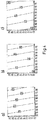
- the performance is determined by means of in Fig. 3 shown and in the memory of the control device 50 existing maps or curves set.
- the control device 50 furthermore has an ammeter (not shown), with which the current actually flowing between anode and cathode of the electrolysis cell 10 can be determined.
- the desired concentration range for different powers of the electrolysis plant lies with the in Fig. 3 maps shown in each case on the bottom left to top right extending strip-shaped areas and is each provided with the reference numeral 60.
- the operation of the control device 50 is again using the in Fig. 2 explained control schemes explained.
- the input variable 52 forms the required fill level of the reservoir 30.
- the control device 50 determines from the input variable 52 and the measured controlled variable 53 (measured fill level of the reservoir 30) the difference and determines therefrom the control demand 55 with regard to the power of the electrolysis system. This is done with the help of multi-dimensional maps 56, for example, the in Fig. 3 maps shown realized.
- the removal of NaOCl solution from the reservoir 30 acts as a disturbance 57.
- the control device 50 has properties of a P, I or D controller or combinations thereof and / or a fuzzy controller.
- the control device 50 strives to increase the performance of the electrolysis system.
- the operating point of the electrolysis plant in the in Fig. 3 maps shown, namely the bottom left to top right extending strip-shaped areas 60, moved from bottom to top.
- the new operating point is for example at a higher cell flow, a corresponding higher Solezuschreibmenge and / or a corresponding higher fresh water supply. If the corresponding values for the parameters of the electrolysis plant are determined, these are transmitted to the corresponding setting and detection devices, namely an increased value for the amount of fresh water to be supplied and for the amount of brine to be supplied, and an increased value for the cell flow.
- the Soledosierpumpe 17 then sets the desired value of the brine amount, the proportional valve 9, the desired value of the fresh water amount and the controller 50, the desired electrode current, so that subsequently the desired performance of the electrolysis plant is achieved, generates the desired amount of NaOCl solution and back into the reservoir 30 can be fed.
- the control according to the invention takes into account in particular for a membrane cell electrolysis system with brine return (eg see Fig. 1 ) the knowledge that the brine flow through the electrolytic cell 10 within the limits mentioned has only a very small influence on the amount of product and product concentration. In contrast, the brine flow has a greater influence on the temperature behavior in the electrolysis cell (see FIG. 3 ). It could therefore, for example, the amount of brine substantially kept constant and only the amount of fresh water supplied and the cell current can be changed if the temperature behavior is still acceptable. However, since some of the caustic soda produced in the production process is used for pH correction, the desired pH value of the product may have to be adjusted by other measures.
- a continuous electrolysis determines in particular the mixing ratio (amount of brine fed / amount of fresh water supplied) the brine entry in the reactor.
- a different mixing ratio can lead to an undesired change in the product concentration.
- the above-indicated mixing ratio is kept constant.
- the flow of NaOCl solution in the region of the pumps of the take-off device 40 e.g. the flow rate through the pumps 32, 33, 34, measured as a measure of the amount of NaOCl solution requested by the removal device 40 and determined from this the product removal per unit time and based on this analogous to the above procedure, the control of the power of the electrolysis plant 5 by means of Control device 50 are performed.
- Fig. 4 shows the temperature dependence of the emerging from the electrolysis plant 5 at the output 25 product depending on the supplied amount of brine, the amount of fresh water supplied and the cell current.
- the control device 50 operates in a preferred embodiment such that the temperature of the NaOCl solution does not exceed a temperature of 35 ° C, otherwise, as described above, the life of the components of the electrolysis plant is shortened.
- the temperature of the product which based on the stored in the control device 50 maps (see Fig. 3 ), therefore acts as a further disturbance in this preferred embodiment in the Fig. 2 illustrated control circuit. If necessary, an operating point determined only on the basis of the quantity taken off or of the filling level of the storage container is corrected, if, for example, based on the in Fig.
- the temperature of the product may be determined by the temperature measuring device 49.
- the control device 50 can then, starting from this temperature, shift the operating point of the electrolysis plant correspondingly to lower powers if this is too high.
- the ambient temperature detected by the temperature measuring device 46 and the fresh water supply 11 detected by the temperature measuring device 47 may optionally be included as additional parameters in the determination of the product temperature by the control device 50.
- Due to the use of a PID and / or fuzzy control for adjusting the operating point of the electrolysis plant 5 in the inventive method or device according to the invention depends on a decrease in NaOCl solution per unit time or a level of a reservoir self-optimization, especially in a membrane cell electrolysis achieved, which allows to extend the operating time and operate the system over long distances below the maximum power. As a result, parts of the system are loaded less and OH-radical formation is reduced.
Landscapes
- Chemical & Material Sciences (AREA)
- Engineering & Computer Science (AREA)
- Organic Chemistry (AREA)
- Chemical Kinetics & Catalysis (AREA)
- Electrochemistry (AREA)
- Metallurgy (AREA)
- Materials Engineering (AREA)
- Automation & Control Theory (AREA)
- Analytical Chemistry (AREA)
- Life Sciences & Earth Sciences (AREA)
- Inorganic Chemistry (AREA)
- Water Supply & Treatment (AREA)
- Environmental & Geological Engineering (AREA)
- Hydrology & Water Resources (AREA)
- General Chemical & Material Sciences (AREA)
- Electrolytic Production Of Non-Metals, Compounds, Apparatuses Therefor (AREA)
- Water Treatment By Electricity Or Magnetism (AREA)
Priority Applications (3)
| Application Number | Priority Date | Filing Date | Title |
|---|---|---|---|
| RS20200129A RS59930B1 (sr) | 2012-04-24 | 2013-04-17 | Elektrolizni sistem i postupak za njegovo korišćenje |
| PL13164105T PL2657193T3 (pl) | 2012-04-24 | 2013-04-17 | Instalacja do elektrolizy i metoda jej eksploatacji |
| HRP20200204TT HRP20200204T1 (hr) | 2012-04-24 | 2020-02-07 | Uređaj za elektrolizu i postupak za upravljanje istim |
Applications Claiming Priority (1)
| Application Number | Priority Date | Filing Date | Title |
|---|---|---|---|
| DE102012103609A DE102012103609A1 (de) | 2012-04-24 | 2012-04-24 | Elektrolyseanlage und Verfahren zum Betreiben derselben |
Publications (3)
| Publication Number | Publication Date |
|---|---|
| EP2657193A2 EP2657193A2 (de) | 2013-10-30 |
| EP2657193A3 EP2657193A3 (de) | 2016-12-28 |
| EP2657193B1 true EP2657193B1 (de) | 2019-11-27 |
Family
ID=48143110
Family Applications (1)
| Application Number | Title | Priority Date | Filing Date |
|---|---|---|---|
| EP13164105.2A Active EP2657193B1 (de) | 2012-04-24 | 2013-04-17 | Elektrolyseanlage und verfahren zum betreiben derselben |
Country Status (5)
| Country | Link |
|---|---|
| EP (1) | EP2657193B1 (pl) |
| DE (1) | DE102012103609A1 (pl) |
| HR (1) | HRP20200204T1 (pl) |
| PL (1) | PL2657193T3 (pl) |
| RS (1) | RS59930B1 (pl) |
Families Citing this family (2)
| Publication number | Priority date | Publication date | Assignee | Title |
|---|---|---|---|---|
| GB2528650A (en) * | 2014-07-16 | 2016-02-03 | Gaffey Technical Services Ltd | An electrochlorination apparatus |
| CN113200632A (zh) * | 2021-05-13 | 2021-08-03 | 舟山市润润环保能源科技有限公司 | 一种河涌入海口水体脱氮的方法 |
Family Cites Families (5)
| Publication number | Priority date | Publication date | Assignee | Title |
|---|---|---|---|---|
| US4329215A (en) | 1980-06-13 | 1982-05-11 | Frank Scoville | Sodium hypochorite production and storage system |
| US5858201A (en) * | 1994-07-29 | 1999-01-12 | Toto, Ltd. | Strong acid sterilizing liquid containing hypochlorous acid at a low concentration, method and apparatus for generating same, and apparatus for generating and dispensing same |
| DE29722822U1 (de) * | 1997-12-24 | 1998-04-02 | Dinotec GmbH, 63477 Maintal | Elektrolysegerät |
| FR2865479B1 (fr) * | 2004-01-23 | 2006-12-01 | Cie Ind De Filtration Et D Equ | Procede et dispositif de fabrication d'une solution d'hypochlorite par electrolyse de chlorure |
| CN101360686A (zh) * | 2005-12-09 | 2009-02-04 | 肯尼思·罗兰·瓦尔科 | 连续式次氯酸盐发生器 |
-
2012
- 2012-04-24 DE DE102012103609A patent/DE102012103609A1/de not_active Withdrawn
-
2013
- 2013-04-17 PL PL13164105T patent/PL2657193T3/pl unknown
- 2013-04-17 RS RS20200129A patent/RS59930B1/sr unknown
- 2013-04-17 EP EP13164105.2A patent/EP2657193B1/de active Active
-
2020
- 2020-02-07 HR HRP20200204TT patent/HRP20200204T1/hr unknown
Non-Patent Citations (1)
| Title |
|---|
| None * |
Also Published As
| Publication number | Publication date |
|---|---|
| EP2657193A3 (de) | 2016-12-28 |
| EP2657193A2 (de) | 2013-10-30 |
| PL2657193T3 (pl) | 2020-10-19 |
| RS59930B1 (sr) | 2020-03-31 |
| HRP20200204T1 (hr) | 2020-05-15 |
| DE102012103609A1 (de) | 2013-10-24 |
Similar Documents
| Publication | Publication Date | Title |
|---|---|---|
| EP1986959B1 (de) | Verfahren zur herstellung eines desinfektionsmittels durch elektrochemische aktivierung (eca) von wasser | |
| DE69707388T2 (de) | Apparat zur Herstellung einer sterilisierenden Lösung | |
| DE69409996T2 (de) | Verfahren und Vorrichtung zur Erzeugung von elektrolytischem Wasser | |
| EP2481713B1 (de) | Verfahren zum Betrieb einer Wasserenthärtungsanlage und Wasserenthärtungsanlage zur Durchführung des Verfahrens | |
| EP2231526B1 (de) | Verfahren zum betrieb einer wasserenthärtungsanlage mit zwei kalibrierkennlinien und zugehörige wasserenthärtungsanlage | |
| DE102010028756A1 (de) | Verfahren zur Regeneration einer Wasserenthärtungsanlage | |
| WO2010025697A1 (de) | Aussetzen von messgrössenauswertungen in einer automatischen wasserenthärtungsanlage bei vorliegen von definierten betriebssituationen | |
| CA2732443A1 (en) | Electrochemical device | |
| DE69724289T2 (de) | Elektrochemische behandlung von flüssigkeiten z.b. wasser | |
| EP2191721A1 (de) | Desinfektionsmittel auf Basis hypochloriger Säure und deren Salze sowie Verfahren zu seiner Herstellung mittels elektrochemischer Aktivierung | |
| DE102006007931A1 (de) | Verfahren zur Herstellung eines Desinfektionsmittels durch elektrochemische Aktivierung (ECA) von Wasser und Verfahren zur Desinfektion von Wasser mittels eines solchen Desinfektionsmittels | |
| EP1841899A1 (de) | Verfahren und vorrichtung zur herstellung einer alkalimetall-hypochlorit-lösung | |
| EP3448896B1 (de) | Verfahren zur herstellung eines trockenverfestigers aus glyoxyliertem polyacrylamid | |
| EP2142471B1 (de) | Verfahren zur herstellung von chlordioxid | |
| EP2533036B1 (de) | Verfahren zum Betrieb eines Leitfähigkeitssensors, insbesondere zur Reinigung der Elektrodenoberflächen des Leitfähigkeitssensors, und Wasserenthärter enthaltend einen solchen Leitfähigkeitssensor | |
| EP3524577A1 (de) | Wasserenthärtungsanlage mit bestimmung einer regeneriermittelkonzentration über eine förderdauer und ein fördervolumen oder eine fördermasse | |
| EP3867422A1 (de) | Elektrochemisches system zur synthese von wässriger oxidationsmittel-lösung | |
| EP2657193A2 (de) | Elektrolyseanlage und Verfahren zum Betreiben derselben | |
| EP2528868B1 (de) | Verfahren zum betrieb einer wasserbehandlungsanlage mit korrektur von kalibrierkennlinien | |
| DE102014010901A1 (de) | ECA Reaktor zur Erzeugung eines aktivierten hypochlorithaltigen Desinfektionsmittels | |
| DE112018004014T5 (de) | Verfahren und System zum Steuern der Desinfektion in rezirkulierenden Wassersystemen | |
| DE102011006176A1 (de) | Verfahren zum Betrieb einer Dosierpumpe und zugehörige Dosiervorrichtung | |
| DE102006058454B4 (de) | Verfahren zur elektrolytischen Herstellung einer schwachen Natriumhypochloritlösung mit differenzdruckgesteuerter pH- und Redoxregelung mittels Elektrolysemembranzellen aus Wasser (H2O) und Kochsalz (NaCl) | |
| DE102006043267A1 (de) | Verfahren zur Herstellung eines Desinfektionsmittels durch elektrochemische Aktivierung (ECA) von Wasser und Verfahren zur Desinfektion von Wasser mittels eines solchen Desinfektionsmittels | |
| EP2477951A1 (de) | Vorrichtung zur wasserentkeimung durch anodische oxidation |
Legal Events
| Date | Code | Title | Description |
|---|---|---|---|
| PUAI | Public reference made under article 153(3) epc to a published international application that has entered the european phase |
Free format text: ORIGINAL CODE: 0009012 |
|
| AK | Designated contracting states |
Kind code of ref document: A2 Designated state(s): AL AT BE BG CH CY CZ DE DK EE ES FI FR GB GR HR HU IE IS IT LI LT LU LV MC MK MT NL NO PL PT RO RS SE SI SK SM TR |
|
| AX | Request for extension of the european patent |
Extension state: BA ME |
|
| RAP1 | Party data changed (applicant data changed or rights of an application transferred) |
Owner name: DINOTEC GMBH |
|
| PUAL | Search report despatched |
Free format text: ORIGINAL CODE: 0009013 |
|
| AK | Designated contracting states |
Kind code of ref document: A3 Designated state(s): AL AT BE BG CH CY CZ DE DK EE ES FI FR GB GR HR HU IE IS IT LI LT LU LV MC MK MT NL NO PL PT RO RS SE SI SK SM TR |
|
| AX | Request for extension of the european patent |
Extension state: BA ME |
|
| RIC1 | Information provided on ipc code assigned before grant |
Ipc: C25B 15/02 20060101ALI20161121BHEP Ipc: C02F 103/42 20060101ALN20161121BHEP Ipc: C25B 1/26 20060101ALI20161121BHEP Ipc: C02F 1/461 20060101ALN20161121BHEP Ipc: C02F 1/467 20060101AFI20161121BHEP |
|
| STAA | Information on the status of an ep patent application or granted ep patent |
Free format text: STATUS: REQUEST FOR EXAMINATION WAS MADE |
|
| 17P | Request for examination filed |
Effective date: 20170602 |
|
| RBV | Designated contracting states (corrected) |
Designated state(s): AL AT BE BG CH CY CZ DE DK EE ES FI FR GB GR HR HU IE IS IT LI LT LU LV MC MK MT NL NO PL PT RO RS SE SI SK SM TR |
|
| RIC1 | Information provided on ipc code assigned before grant |
Ipc: C25B 1/26 20060101ALI20190617BHEP Ipc: C02F 1/461 20060101ALN20190617BHEP Ipc: C02F 1/467 20060101AFI20190617BHEP Ipc: C25B 15/02 20060101ALI20190617BHEP Ipc: C02F 103/42 20060101ALN20190617BHEP |
|
| GRAP | Despatch of communication of intention to grant a patent |
Free format text: ORIGINAL CODE: EPIDOSNIGR1 |
|
| STAA | Information on the status of an ep patent application or granted ep patent |
Free format text: STATUS: GRANT OF PATENT IS INTENDED |
|
| INTG | Intention to grant announced |
Effective date: 20190730 |
|
| GRAS | Grant fee paid |
Free format text: ORIGINAL CODE: EPIDOSNIGR3 |
|
| GRAA | (expected) grant |
Free format text: ORIGINAL CODE: 0009210 |
|
| STAA | Information on the status of an ep patent application or granted ep patent |
Free format text: STATUS: THE PATENT HAS BEEN GRANTED |
|
| AK | Designated contracting states |
Kind code of ref document: B1 Designated state(s): AL AT BE BG CH CY CZ DE DK EE ES FI FR GB GR HR HU IE IS IT LI LT LU LV MC MK MT NL NO PL PT RO RS SE SI SK SM TR |
|
| REG | Reference to a national code |
Ref country code: GB Ref legal event code: FG4D Free format text: NOT ENGLISH |
|
| REG | Reference to a national code |
Ref country code: CH Ref legal event code: EP |
|
| REG | Reference to a national code |
Ref country code: DE Ref legal event code: R096 Ref document number: 502013013960 Country of ref document: DE |
|
| REG | Reference to a national code |
Ref country code: AT Ref legal event code: REF Ref document number: 1206477 Country of ref document: AT Kind code of ref document: T Effective date: 20191215 |
|
| REG | Reference to a national code |
Ref country code: IE Ref legal event code: FG4D Free format text: LANGUAGE OF EP DOCUMENT: GERMAN |
|
| REG | Reference to a national code |
Ref country code: CH Ref legal event code: NV Representative=s name: ISLER AND PEDRAZZINI AG, CH |
|
| REG | Reference to a national code |
Ref country code: HR Ref legal event code: TUEP Ref document number: P20200204T Country of ref document: HR |
|
| REG | Reference to a national code |
Ref country code: NL Ref legal event code: FP |
|
| REG | Reference to a national code |
Ref country code: LT Ref legal event code: MG4D |
|
| PG25 | Lapsed in a contracting state [announced via postgrant information from national office to epo] |
Ref country code: BG Free format text: LAPSE BECAUSE OF FAILURE TO SUBMIT A TRANSLATION OF THE DESCRIPTION OR TO PAY THE FEE WITHIN THE PRESCRIBED TIME-LIMIT Effective date: 20200227 Ref country code: FI Free format text: LAPSE BECAUSE OF FAILURE TO SUBMIT A TRANSLATION OF THE DESCRIPTION OR TO PAY THE FEE WITHIN THE PRESCRIBED TIME-LIMIT Effective date: 20191127 Ref country code: LV Free format text: LAPSE BECAUSE OF FAILURE TO SUBMIT A TRANSLATION OF THE DESCRIPTION OR TO PAY THE FEE WITHIN THE PRESCRIBED TIME-LIMIT Effective date: 20191127 Ref country code: NO Free format text: LAPSE BECAUSE OF FAILURE TO SUBMIT A TRANSLATION OF THE DESCRIPTION OR TO PAY THE FEE WITHIN THE PRESCRIBED TIME-LIMIT Effective date: 20200227 Ref country code: SE Free format text: LAPSE BECAUSE OF FAILURE TO SUBMIT A TRANSLATION OF THE DESCRIPTION OR TO PAY THE FEE WITHIN THE PRESCRIBED TIME-LIMIT Effective date: 20191127 Ref country code: GR Free format text: LAPSE BECAUSE OF FAILURE TO SUBMIT A TRANSLATION OF THE DESCRIPTION OR TO PAY THE FEE WITHIN THE PRESCRIBED TIME-LIMIT Effective date: 20200228 Ref country code: LT Free format text: LAPSE BECAUSE OF FAILURE TO SUBMIT A TRANSLATION OF THE DESCRIPTION OR TO PAY THE FEE WITHIN THE PRESCRIBED TIME-LIMIT Effective date: 20191127 Ref country code: ES Free format text: LAPSE BECAUSE OF FAILURE TO SUBMIT A TRANSLATION OF THE DESCRIPTION OR TO PAY THE FEE WITHIN THE PRESCRIBED TIME-LIMIT Effective date: 20191127 |
|
| REG | Reference to a national code |
Ref country code: HR Ref legal event code: ODRP Ref document number: P20200204T Country of ref document: HR Payment date: 20200316 Year of fee payment: 8 |
|
| REG | Reference to a national code |
Ref country code: HR Ref legal event code: T1PR Ref document number: P20200204 Country of ref document: HR |
|
| PG25 | Lapsed in a contracting state [announced via postgrant information from national office to epo] |
Ref country code: IS Free format text: LAPSE BECAUSE OF FAILURE TO SUBMIT A TRANSLATION OF THE DESCRIPTION OR TO PAY THE FEE WITHIN THE PRESCRIBED TIME-LIMIT Effective date: 20200327 |
|
| PG25 | Lapsed in a contracting state [announced via postgrant information from national office to epo] |
Ref country code: AL Free format text: LAPSE BECAUSE OF FAILURE TO SUBMIT A TRANSLATION OF THE DESCRIPTION OR TO PAY THE FEE WITHIN THE PRESCRIBED TIME-LIMIT Effective date: 20191127 |
|
| PG25 | Lapsed in a contracting state [announced via postgrant information from national office to epo] |
Ref country code: RO Free format text: LAPSE BECAUSE OF FAILURE TO SUBMIT A TRANSLATION OF THE DESCRIPTION OR TO PAY THE FEE WITHIN THE PRESCRIBED TIME-LIMIT Effective date: 20191127 Ref country code: CZ Free format text: LAPSE BECAUSE OF FAILURE TO SUBMIT A TRANSLATION OF THE DESCRIPTION OR TO PAY THE FEE WITHIN THE PRESCRIBED TIME-LIMIT Effective date: 20191127 Ref country code: DK Free format text: LAPSE BECAUSE OF FAILURE TO SUBMIT A TRANSLATION OF THE DESCRIPTION OR TO PAY THE FEE WITHIN THE PRESCRIBED TIME-LIMIT Effective date: 20191127 Ref country code: EE Free format text: LAPSE BECAUSE OF FAILURE TO SUBMIT A TRANSLATION OF THE DESCRIPTION OR TO PAY THE FEE WITHIN THE PRESCRIBED TIME-LIMIT Effective date: 20191127 Ref country code: PT Free format text: LAPSE BECAUSE OF FAILURE TO SUBMIT A TRANSLATION OF THE DESCRIPTION OR TO PAY THE FEE WITHIN THE PRESCRIBED TIME-LIMIT Effective date: 20200419 |
|
| REG | Reference to a national code |
Ref country code: DE Ref legal event code: R097 Ref document number: 502013013960 Country of ref document: DE |
|
| PG25 | Lapsed in a contracting state [announced via postgrant information from national office to epo] |
Ref country code: SK Free format text: LAPSE BECAUSE OF FAILURE TO SUBMIT A TRANSLATION OF THE DESCRIPTION OR TO PAY THE FEE WITHIN THE PRESCRIBED TIME-LIMIT Effective date: 20191127 Ref country code: SM Free format text: LAPSE BECAUSE OF FAILURE TO SUBMIT A TRANSLATION OF THE DESCRIPTION OR TO PAY THE FEE WITHIN THE PRESCRIBED TIME-LIMIT Effective date: 20191127 |
|
| PGFP | Annual fee paid to national office [announced via postgrant information from national office to epo] |
Ref country code: BE Payment date: 20200420 Year of fee payment: 8 Ref country code: GB Payment date: 20200423 Year of fee payment: 8 |
|
| PGFP | Annual fee paid to national office [announced via postgrant information from national office to epo] |
Ref country code: AT Payment date: 20200421 Year of fee payment: 8 |
|
| PLBE | No opposition filed within time limit |
Free format text: ORIGINAL CODE: 0009261 |
|
| STAA | Information on the status of an ep patent application or granted ep patent |
Free format text: STATUS: NO OPPOSITION FILED WITHIN TIME LIMIT |
|
| 26N | No opposition filed |
Effective date: 20200828 |
|
| PG25 | Lapsed in a contracting state [announced via postgrant information from national office to epo] |
Ref country code: MC Free format text: LAPSE BECAUSE OF FAILURE TO SUBMIT A TRANSLATION OF THE DESCRIPTION OR TO PAY THE FEE WITHIN THE PRESCRIBED TIME-LIMIT Effective date: 20191127 Ref country code: SI Free format text: LAPSE BECAUSE OF FAILURE TO SUBMIT A TRANSLATION OF THE DESCRIPTION OR TO PAY THE FEE WITHIN THE PRESCRIBED TIME-LIMIT Effective date: 20191127 |
|
| PG25 | Lapsed in a contracting state [announced via postgrant information from national office to epo] |
Ref country code: IT Free format text: LAPSE BECAUSE OF FAILURE TO SUBMIT A TRANSLATION OF THE DESCRIPTION OR TO PAY THE FEE WITHIN THE PRESCRIBED TIME-LIMIT Effective date: 20191127 Ref country code: LU Free format text: LAPSE BECAUSE OF NON-PAYMENT OF DUE FEES Effective date: 20200417 |
|
| PG25 | Lapsed in a contracting state [announced via postgrant information from national office to epo] |
Ref country code: IE Free format text: LAPSE BECAUSE OF NON-PAYMENT OF DUE FEES Effective date: 20200417 |
|
| REG | Reference to a national code |
Ref country code: HR Ref legal event code: ODRP Ref document number: P20200204 Country of ref document: HR Payment date: 20210413 Year of fee payment: 9 |
|
| REG | Reference to a national code |
Ref country code: AT Ref legal event code: MM01 Ref document number: 1206477 Country of ref document: AT Kind code of ref document: T Effective date: 20210417 |
|
| GBPC | Gb: european patent ceased through non-payment of renewal fee |
Effective date: 20210417 |
|
| REG | Reference to a national code |
Ref country code: BE Ref legal event code: MM Effective date: 20210430 |
|
| PG25 | Lapsed in a contracting state [announced via postgrant information from national office to epo] |
Ref country code: GB Free format text: LAPSE BECAUSE OF NON-PAYMENT OF DUE FEES Effective date: 20210417 Ref country code: AT Free format text: LAPSE BECAUSE OF NON-PAYMENT OF DUE FEES Effective date: 20210417 |
|
| REG | Reference to a national code |
Ref country code: HR Ref legal event code: ODRP Ref document number: P20200204 Country of ref document: HR Payment date: 20220408 Year of fee payment: 10 |
|
| PG25 | Lapsed in a contracting state [announced via postgrant information from national office to epo] |
Ref country code: TR Free format text: LAPSE BECAUSE OF FAILURE TO SUBMIT A TRANSLATION OF THE DESCRIPTION OR TO PAY THE FEE WITHIN THE PRESCRIBED TIME-LIMIT Effective date: 20191127 Ref country code: MT Free format text: LAPSE BECAUSE OF FAILURE TO SUBMIT A TRANSLATION OF THE DESCRIPTION OR TO PAY THE FEE WITHIN THE PRESCRIBED TIME-LIMIT Effective date: 20191127 Ref country code: CY Free format text: LAPSE BECAUSE OF FAILURE TO SUBMIT A TRANSLATION OF THE DESCRIPTION OR TO PAY THE FEE WITHIN THE PRESCRIBED TIME-LIMIT Effective date: 20191127 |
|
| PG25 | Lapsed in a contracting state [announced via postgrant information from national office to epo] |
Ref country code: MK Free format text: LAPSE BECAUSE OF FAILURE TO SUBMIT A TRANSLATION OF THE DESCRIPTION OR TO PAY THE FEE WITHIN THE PRESCRIBED TIME-LIMIT Effective date: 20191127 |
|
| PG25 | Lapsed in a contracting state [announced via postgrant information from national office to epo] |
Ref country code: BE Free format text: LAPSE BECAUSE OF NON-PAYMENT OF DUE FEES Effective date: 20210430 |
|
| REG | Reference to a national code |
Ref country code: HR Ref legal event code: ODRP Ref document number: P20200204 Country of ref document: HR Payment date: 20230406 Year of fee payment: 11 |
|
| P01 | Opt-out of the competence of the unified patent court (upc) registered |
Effective date: 20230505 |
|
| P02 | Opt-out of the competence of the unified patent court (upc) changed |
Effective date: 20230530 |
|
| REG | Reference to a national code |
Ref country code: HR Ref legal event code: ODRP Ref document number: P20200204 Country of ref document: HR Payment date: 20240409 Year of fee payment: 12 |
|
| PGFP | Annual fee paid to national office [announced via postgrant information from national office to epo] |
Ref country code: NL Payment date: 20240422 Year of fee payment: 12 |
|
| PGFP | Annual fee paid to national office [announced via postgrant information from national office to epo] |
Ref country code: HR Payment date: 20240409 Year of fee payment: 12 Ref country code: RS Payment date: 20240417 Year of fee payment: 12 |
|
| PGFP | Annual fee paid to national office [announced via postgrant information from national office to epo] |
Ref country code: FR Payment date: 20240419 Year of fee payment: 12 |
|
| PGFP | Annual fee paid to national office [announced via postgrant information from national office to epo] |
Ref country code: PL Payment date: 20250408 Year of fee payment: 13 Ref country code: DE Payment date: 20250429 Year of fee payment: 13 |
|
| PGFP | Annual fee paid to national office [announced via postgrant information from national office to epo] |
Ref country code: CH Payment date: 20250501 Year of fee payment: 13 |
|
| REG | Reference to a national code |
Ref country code: HR Ref legal event code: PBON Ref document number: P20200204 Country of ref document: HR Effective date: 20250417 |
|
| REG | Reference to a national code |
Ref country code: NL Ref legal event code: MM Effective date: 20250501 |
|
| PG25 | Lapsed in a contracting state [announced via postgrant information from national office to epo] |
Ref country code: NL Free format text: LAPSE BECAUSE OF NON-PAYMENT OF DUE FEES Effective date: 20250501 Ref country code: FR Free format text: LAPSE BECAUSE OF NON-PAYMENT OF DUE FEES Effective date: 20250430 Ref country code: HR Free format text: LAPSE BECAUSE OF NON-PAYMENT OF DUE FEES Effective date: 20250417 |
|
| PG25 | Lapsed in a contracting state [announced via postgrant information from national office to epo] |
Ref country code: RS Free format text: LAPSE BECAUSE OF NON-PAYMENT OF DUE FEES Effective date: 20250417 |
|
| REG | Reference to a national code |
Ref country code: CH Ref legal event code: U11 Free format text: ST27 STATUS EVENT CODE: U-0-0-U10-U11 (AS PROVIDED BY THE NATIONAL OFFICE) Effective date: 20260501 |