EP2657175B1 - Retaining Pin Assembly for a Lifting System. - Google Patents
Retaining Pin Assembly for a Lifting System. Download PDFInfo
- Publication number
- EP2657175B1 EP2657175B1 EP13164786.9A EP13164786A EP2657175B1 EP 2657175 B1 EP2657175 B1 EP 2657175B1 EP 13164786 A EP13164786 A EP 13164786A EP 2657175 B1 EP2657175 B1 EP 2657175B1
- Authority
- EP
- European Patent Office
- Prior art keywords
- hook
- lifting system
- shaft
- lock
- set forth
- Prior art date
- Legal status (The legal status is an assumption and is not a legal conclusion. Google has not performed a legal analysis and makes no representation as to the accuracy of the status listed.)
- Active
Links
Images




Classifications
-
- F—MECHANICAL ENGINEERING; LIGHTING; HEATING; WEAPONS; BLASTING
- F16—ENGINEERING ELEMENTS AND UNITS; GENERAL MEASURES FOR PRODUCING AND MAINTAINING EFFECTIVE FUNCTIONING OF MACHINES OR INSTALLATIONS; THERMAL INSULATION IN GENERAL
- F16B—DEVICES FOR FASTENING OR SECURING CONSTRUCTIONAL ELEMENTS OR MACHINE PARTS TOGETHER, e.g. NAILS, BOLTS, CIRCLIPS, CLAMPS, CLIPS OR WEDGES; JOINTS OR JOINTING
- F16B19/00—Bolts without screw-thread; Pins, including deformable elements; Rivets
-
- B—PERFORMING OPERATIONS; TRANSPORTING
- B66—HOISTING; LIFTING; HAULING
- B66C—CRANES; LOAD-ENGAGING ELEMENTS OR DEVICES FOR CRANES, CAPSTANS, WINCHES, OR TACKLES
- B66C1/00—Load-engaging elements or devices attached to lifting or lowering gear of cranes or adapted for connection therewith for transmitting lifting forces to articles or groups of articles
- B66C1/10—Load-engaging elements or devices attached to lifting or lowering gear of cranes or adapted for connection therewith for transmitting lifting forces to articles or groups of articles by mechanical means
- B66C1/22—Rigid members, e.g. L-shaped members, with parts engaging the under surface of the loads; Crane hooks
- B66C1/34—Crane hooks
-
- F—MECHANICAL ENGINEERING; LIGHTING; HEATING; WEAPONS; BLASTING
- F16—ENGINEERING ELEMENTS AND UNITS; GENERAL MEASURES FOR PRODUCING AND MAINTAINING EFFECTIVE FUNCTIONING OF MACHINES OR INSTALLATIONS; THERMAL INSULATION IN GENERAL
- F16B—DEVICES FOR FASTENING OR SECURING CONSTRUCTIONAL ELEMENTS OR MACHINE PARTS TOGETHER, e.g. NAILS, BOLTS, CIRCLIPS, CLAMPS, CLIPS OR WEDGES; JOINTS OR JOINTING
- F16B21/00—Means for preventing relative axial movement of a pin, spigot, shaft or the like and a member surrounding it; Stud-and-socket releasable fastenings
- F16B21/10—Means for preventing relative axial movement of a pin, spigot, shaft or the like and a member surrounding it; Stud-and-socket releasable fastenings by separate parts
- F16B21/12—Means for preventing relative axial movement of a pin, spigot, shaft or the like and a member surrounding it; Stud-and-socket releasable fastenings by separate parts with locking-pins or split-pins thrust into holes
Definitions
- the present invention is directed to a lifting system comprising a retaining pin assembly.
- the present invention is directed to a lifting system wherein a retaining pin and a retaining ring maintain a lock arm or bail arm in place in a closed position when in use and wherein the retaining pin may be partially retracted so that the retaining ring resides in a recess in the lock arm or bail arm.
- a hook or multiple hooks are utilized for lifting.
- An elevator link, wire line, chain or other load is installed in the hook in order to support a load.
- the hook When in use, the hook is kept in a closed position by a lock arm, a bail arm or a latch.
- the lock arm is kept in the closed position by a retaining pin or pins.
- the lock arm, bail arm or latch is unfastened by retracting the retaining pin or pins.
- a retaining pin passes through the lock arm and a hook cam and locks or secures the lock arm in place.
- a retaining pin also passes through the lock arm and a hook prorig.
- the pins may have a threaded connection to the lock arm or may be held by a cotter pin.
- the lock arms are engaged for use and disengaged in the field under a wide variety of conditions. It would be advantageous to be able to retract the retaining pin or pins from the lock arm without removing the retaining pin or pins from the lifting assembly.
- US 2006/0119121 A1 discloses lifting system according to the preamble of claim 1 comprising a retaining keeper assembly .
- a shank is provided having a plurality of circumferential grooves perpendicular to an axis of the shank.
- a thrust bearing surrounds the shank and is supported by the hoisting device.
- a split retaining collar having a plurality of interior circular protrusions mates with the circumferential grooves in the shank to prevent axial movement of the shank.
- a lifting system comprising a retaining pin assembly wherein a retaining pin will pass through the lock arm when in a use position and wherein the retaining pin may be retracted without disengaging the retaining pin from the lock arm.
- It is a further object and purpose of the present invention to provide a lifting system comprising a retaining pin assembly having one or more grooves or slots in a retaining pin shaft to hold a retaining ring thereon.
- It is a further object and purpose of the present invention to provide a lifting system comprising a retaining pin assembly with a retaining ring wherein the retaining ring may be withdrawn into a recess in a lock arm during assembly and disassembly.
- the present invention is directed to a lifting system comprising a retaining pin assembly according to claim 1.
- a first hook is retained in a closed position by a first hook lock arm assembly and a second hook is retained in a closed position by a second hook lock arm assembly.
- the lock arm assembly comprises a pair of parallel lock arms joined together by a cross arm. The first ends of the lock arm assembly have apertures therethrough which surround a hook cam.
- a hook cam retaining pin includes a head with an extending shaft passing through the hook cam opening and also through the lock arm first end apertures.
- the lock arm assembly also includes an opposed second end with apertures therethrough which align with an opening through a hook prong.
- the second ends of the lock arm assembly surround the hook prong.
- a hook prong retaining pin includes a head with an extending shaft passing through the hook prong opening and also through the lock arm assembly second end apertures 28.
- three shaft grooves are arranged around the shaft.
- the grooves are parallel to each other and parallel to an axis of the shaft.
- a retaining ring fits around the exterior circumference of the shaft and includes a series of inwardly extending tabs received in the grooves. The retaining ring and the inwardly extending tabs received in the grooves permit axial movement of the shaft but prohibit removal of the retaining pin from the lock arm assembly.
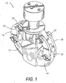
- Figure 1 illustrates a perspective view of one preferred embodiment of the present invention 10 with a two prong tubing block hook subassembly.
- Figure 2 illustrates a side view and
- Figure 3 illustrates a front view of the tubing block hook subassembly shown in Figure 1 .
- the subassembly 10 includes a first hook 12 and a second hook 14. It will be appreciated that other configurations, such as one, three, or four hook systems, might be employed within the spirit and scope of the present invention.
- An elevator link, a wire line, chain or other load supporting mechanism would reside within the prongs of the hook 12 and 14 when in use.
- the hooks are either in a closed position for use or an open position for insertion or removal.
- the lifting system 10 is, in turn, a subassembly of an oilfield tubing block (not shown).
- first hook 12 When in use, the first hook 12 is retained in a closed position by a first hook lock arm or bail arm assembly 16 and the second hook 14 is retained in a closed position by a second hook lock arm or ball arm assembly 18.
- the lock arm assemblies 16 and 18 have an arched or arcuate shape.
- Figures 4 and 5 illustrate a front view and a side view of the lifting system 10 with the lock arms 16 and 18 secured in place for use.
- Figures 6 and 7 illustrate a front view and a side view of the lifting assembly, respectively, with one of the lock arms disengaged for disassembly.
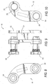
- FIGS 8, 9 and 10 illustrate alternate views of the lock arm assembly 16 apart from the lifting system 10.
- the lock arm assembly 16 has a first end 20 with at least one aperture 26 therethrough as best seen in Figure 10 .
- the aperture 26 aligns with an opening through a hook cam 22 which protrudes from the hook 14.
- a hook cam 22 also protrudes from hook 12.
- the lock arm assembly 16 comprises a pair of parallel lock arms joined together by a cross arm 24 visible in Figure 9 .
- the first ends 20 of the lock arm surround the hook cam 22 as seen in Figure 5 .
- the space between the parallel lock arms is slightly larger than the width of the hook cam 22.
- the lock arm assembly 16 also includes a second end 30 opposed to the first end 20 with at least one aperture 28 therethrough which aligns with an opening through a hook prong 32 which protrudes from the hook 14.
- the second ends 30 of the lock arm assembly 16 surround the hook prong 32 as best seen in Figure 5 .
- the space between the parallel lock arms is slightly larger than the width of the hook prong.
- a hook cam retaining pin 40 includes a head and an extending shaft.
- the retaining pin shaft passes through the opening in the hook cam 22 and also through the lock arm assembly first end 20 aperture 26.
- a hook prong retaining pin 42 includes a head and an extending shaft.
- the retaining pin shaft passes through the opening in the hook prong 32 and also through the lock arm assembly second end 30 aperture 28.
- Figure 11 shows a side view and Figure 12 shows an end view of a hook cam retaining pin 40.
- the hook cam retaining pin 40 is shown in alternate perspective views in Figures 13 and 14 and is shown in exploded view in Figure 15 .
- the hook prong retaining pin 42 (not shown in Figures 11 through 15 ) would have a similar configuration.
- the retaining pin 40 includes a head 50 and a shaft 52 extending therefrom.
- the hook cam retaining pin 40 may include an opening 54 transverse to the shaft at an end opposed to the head 50 to receive a cotter pin 56 or like device.
- At least one shaft slot or groove 60 and in a preferred embodiment three shaft grooves 60, are provided in the shaft 52.
- the grooves 60 are parallel to each other and parallel to an axis of the shaft 52.
- a retaining clip or retaining ring 62 fits around the exterior circumference of the shaft 52 and includes a series of inwardly extending tabs 64. Each of the tabs 64 is received in one of the grooves 60.
- Figures 13 and 14 illustrate alternate perspective views of the retaining pin 40 with the cotter pin 56 inserted therein.
- the head 50 of the retaining pin 40 may be removably attached to the shaft 52 by threads 70 and 72. This arrangement allows for initial installation of the retaining ring 62 around the shaft 52 of the pin 40. Once the head 50 has been threadably secured to the shaft 52, the retaining ring 62 is trapped around the shaft. The retaining ring 62 may be moved axially along the shaft 52 but may not be removed therefrom. The retaining ring 62 and the inwardly extending tabs 64 received in the grooves permit axial movement of the shaft but prohibit removal of the retaining pin from the lock arm assembly.
- threads 74 may be provided to mate with inner threads on an aperture on the lock arm assembly first end 20.
- the cotter pin 56 is removed from the opening 54 in the shaft 52 of the retaining pin 40. This will permit axial movement of the retaining pin 40. Thereafter, the shaft 52 is axially withdrawn from the lock arm assembly 16 until the retaining ring 62 resides in a circular recess in the lock arm assembly 16. The circular recess surrounds and is axially aligned with the aperture 26 through the first end 20. In this position, the shaft 52 of the retaining pin is clear of the opening between the parallel lock arms so that the lock arm assembly 16 may be separated from the hook cam 22.
- the hook prong retaining pin 42 operates in similar fashion with the second end 30 of the lock arm.
Landscapes
- Engineering & Computer Science (AREA)
- Mechanical Engineering (AREA)
- General Engineering & Computer Science (AREA)
- Snaps, Bayonet Connections, Set Pins, And Snap Rings (AREA)
- Earth Drilling (AREA)
- Hooks, Suction Cups, And Attachment By Adhesive Means (AREA)
- Load-Engaging Elements For Cranes (AREA)
Description
- The present invention is directed to a lifting system comprising a retaining pin assembly. In particular, the present invention is directed to a lifting system wherein a retaining pin and a retaining ring maintain a lock arm or bail arm in place in a closed position when in use and wherein the retaining pin may be partially retracted so that the retaining ring resides in a recess in the lock arm or bail arm.
- In a number of lifting or hoisting devices, such as tubing blocks, a hook or multiple hooks are utilized for lifting. An elevator link, wire line, chain or other load is installed in the hook in order to support a load. When in use, the hook is kept in a closed position by a lock arm, a bail arm or a latch. The lock arm is kept in the closed position by a retaining pin or pins. In order to disassemble the lifting device, the lock arm, bail arm or latch is unfastened by retracting the retaining pin or pins.
- In a number of applications, a retaining pin passes through the lock arm and a hook cam and locks or secures the lock arm in place. A retaining pin also passes through the lock arm and a hook prorig. The pins may have a threaded connection to the lock arm or may be held by a cotter pin.
- The lock arms are engaged for use and disengaged in the field under a wide variety of conditions. It would be advantageous to be able to retract the retaining pin or pins from the lock arm without removing the retaining pin or pins from the lifting assembly.
-
US 2006/0119121 A1 discloses lifting system according to the preamble of claim 1 comprising a retaining keeper assembly . A shank is provided having a plurality of circumferential grooves perpendicular to an axis of the shank. A thrust bearing surrounds the shank and is supported by the hoisting device. A split retaining collar having a plurality of interior circular protrusions mates with the circumferential grooves in the shank to prevent axial movement of the shank. - Accordingly, it is a principal object and purpose of the present invention to provide a lifting system comprising a retaining pin assembly wherein a retaining pin will pass through the lock arm when in a use position and wherein the retaining pin may be retracted without disengaging the retaining pin from the lock arm.
- It is a further object and purpose of the present invention to provide a lifting system comprising a retaining pin assembly having one or more grooves or slots in a retaining pin shaft to hold a retaining ring thereon.
- It is a further object and purpose of the present invention to provide a lifting system comprising a retaining pin assembly with a retaining ring wherein the retaining ring may be withdrawn into a recess in a lock arm during assembly and disassembly.
- The present invention is directed to a lifting system comprising a retaining pin assembly according to claim 1. In one embodiment, a first hook is retained in a closed position by a first hook lock arm assembly and a second hook is retained in a closed position by a second hook lock arm assembly. The lock arm assembly comprises a pair of parallel lock arms joined together by a cross arm. The first ends of the lock arm assembly have apertures therethrough which surround a hook cam. A hook cam retaining pin includes a head with an extending shaft passing through the hook cam opening and also through the lock arm first end apertures.
- The lock arm assembly also includes an opposed second end with apertures therethrough which align with an opening through a hook prong. The second ends of the lock arm assembly surround the hook prong.
- A hook prong retaining pin includes a head with an extending shaft passing through the hook prong opening and also through the lock arm assembly
second end apertures 28. - In a preferred embodiment, three shaft grooves are arranged around the shaft. The grooves are parallel to each other and parallel to an axis of the shaft. A retaining ring fits around the exterior circumference of the shaft and includes a series of inwardly extending tabs received in the grooves. The retaining ring and the inwardly extending tabs received in the grooves permit axial movement of the shaft but prohibit removal of the retaining pin from the lock arm assembly.
-
-
Figure 1 illustrates a perspective view,Figure 2 illustrates a side view andFigure 3 illustrates a front view of a preferred embodiment of a retaining pin assembly for a lifting system constructed in accordance with the present invention; -
Figure 4 illustrates a front view andFigure 5 illustrates a side view of the lifting system shown inFigure 1 with the lock arm assemblies secured in place for use; -
Figure 6 illustrates a front view andFigure 7 illustrates a side view of the lifting system shown inFigures 4 and 5 with one of the lock arm assemblies unsecured from the lifting system; -
Figures 8, 9 and 10 illustrate alternate views of a lock arm assembly apart from the lifting system shown inFigure 1 ; -
Figure 11 shows a side view andFigure 12 shows an end view of a retaining pin apart from the lifting system of the present invention; and -
Figures 13 and 14 illustrate alternate views of the retaining pin shown inFigures 11 and 12 whileFigure 15 illustrates an exploded view of the retaining pin. - The embodiments discussed herein are merely illustrative of specific manners in which to make and use the invention and are not to be interpreted as limiting the scope of the instant invention.
- Referring to the drawings in detail,
Figure 1 illustrates a perspective view of one preferred embodiment of thepresent invention 10 with a two prong tubing block hook subassembly.Figure 2 illustrates a side view andFigure 3 illustrates a front view of the tubing block hook subassembly shown inFigure 1 . Thesubassembly 10 includes afirst hook 12 and asecond hook 14. It will be appreciated that other configurations, such as one, three, or four hook systems, might be employed within the spirit and scope of the present invention. - An elevator link, a wire line, chain or other load supporting mechanism (not shown) would reside within the prongs of the
hook - In the present embodiment, the
lifting system 10 is, in turn, a subassembly of an oilfield tubing block (not shown). - When in use, the
first hook 12 is retained in a closed position by a first hook lock arm orbail arm assembly 16 and thesecond hook 14 is retained in a closed position by a second hook lock arm orball arm assembly 18. The lock arm assemblies 16 and 18 have an arched or arcuate shape. -
Figures 4 and 5 illustrate a front view and a side view of thelifting system 10 with thelock arms Figures 6 and 7 illustrate a front view and a side view of the lifting assembly, respectively, with one of the lock arms disengaged for disassembly. -
Figures 8, 9 and 10 illustrate alternate views of thelock arm assembly 16 apart from thelifting system 10. - The
lock arm assembly 16 has afirst end 20 with at least oneaperture 26 therethrough as best seen inFigure 10 . Theaperture 26 aligns with an opening through ahook cam 22 which protrudes from thehook 14. Ahook cam 22 also protrudes fromhook 12. In a preferred embodiment, thelock arm assembly 16 comprises a pair of parallel lock arms joined together by across arm 24 visible inFigure 9 . Thefirst ends 20 of the lock arm surround thehook cam 22 as seen inFigure 5 . The space between the parallel lock arms is slightly larger than the width of thehook cam 22. - The
lock arm assembly 16 also includes asecond end 30 opposed to thefirst end 20 with at least oneaperture 28 therethrough which aligns with an opening through ahook prong 32 which protrudes from thehook 14. - The
second ends 30 of thelock arm assembly 16 surround thehook prong 32 as best seen inFigure 5 . The space between the parallel lock arms is slightly larger than the width of the hook prong. - A hook
cam retaining pin 40 includes a head and an extending shaft. The retaining pin shaft passes through the opening in thehook cam 22 and also through the lock arm assemblyfirst end 20aperture 26. - A hook
prong retaining pin 42 includes a head and an extending shaft. The retaining pin shaft passes through the opening in thehook prong 32 and also through the lock arm assemblysecond end 30aperture 28. -
Figure 11 shows a side view andFigure 12 shows an end view of a hookcam retaining pin 40. The hookcam retaining pin 40 is shown in alternate perspective views inFigures 13 and 14 and is shown in exploded view inFigure 15 . The hook prong retaining pin 42 (not shown inFigures 11 through 15 ) would have a similar configuration. - The retaining
pin 40 includes ahead 50 and ashaft 52 extending therefrom. The hookcam retaining pin 40 may include anopening 54 transverse to the shaft at an end opposed to thehead 50 to receive acotter pin 56 or like device. - At least one shaft slot or
groove 60, and in a preferred embodiment threeshaft grooves 60, are provided in theshaft 52. Thegrooves 60 are parallel to each other and parallel to an axis of theshaft 52. A retaining clip or retainingring 62 fits around the exterior circumference of theshaft 52 and includes a series of inwardly extendingtabs 64. Each of thetabs 64 is received in one of thegrooves 60. -
Figures 13 and 14 illustrate alternate perspective views of the retainingpin 40 with thecotter pin 56 inserted therein. As best seen in the exploded view inFigure 15 , thehead 50 of the retainingpin 40 may be removably attached to theshaft 52 bythreads ring 62 around theshaft 52 of thepin 40. Once thehead 50 has been threadably secured to theshaft 52, the retainingring 62 is trapped around the shaft. The retainingring 62 may be moved axially along theshaft 52 but may not be removed therefrom. The retainingring 62 and the inwardly extendingtabs 64 received in the grooves permit axial movement of the shaft but prohibit removal of the retaining pin from the lock arm assembly. - Additionally, and optionally,
threads 74 may be provided to mate with inner threads on an aperture on the lock arm assemblyfirst end 20. - In order to disassemble the device, the
cotter pin 56 is removed from theopening 54 in theshaft 52 of the retainingpin 40. This will permit axial movement of the retainingpin 40. Thereafter, theshaft 52 is axially withdrawn from thelock arm assembly 16 until the retainingring 62 resides in a circular recess in thelock arm assembly 16. The circular recess surrounds and is axially aligned with theaperture 26 through thefirst end 20. In this position, theshaft 52 of the retaining pin is clear of the opening between the parallel lock arms so that thelock arm assembly 16 may be separated from thehook cam 22. - The hook
prong retaining pin 42 operates in similar fashion with thesecond end 30 of the lock arm.
Claims (18)
- A lifting system comprising a retaining pin assembly wherein said lifting system includes a hook prong (32) and a hook cam (22), wherein said retaining pin assembly comprises:at least one lock or bail arm (16) having a first end (20) with at least one aperture (26) which aligns with an opening through said hook cam (22) and having an opposed second end (30) with at least one aperture (28) which aligns with an opening through said hook prong;a hook cam retaining pin (40) having a head (50) and having a shaft (52) passing through said hook cam opening and said lock or bail arm (16) first end aperture, characterized in that said shaft has at least one groove or slot (60) therein parallel to the axis of said shaft;a retaining ring or clip (62) surrounding said hook cam shaft, said retaining ring or clip having at least one inwardly extending tab (64) received in said at least one shaft groove or slot in order to retain said pin in said lock or bail arm; anda recess in said lock or bail arm (16) to receive said retaining ring or clip (62) therein when said retaining pin is retracted.
- A lifting system as set forth in Claim 1 wherein said at least one lock or bail arm comprises a pair of parallel lock arms joined by a cross arm, wherein said first end of each of said lock arms surround said hook cam and wherein said second end of each of said lock arms surround said hook prong.
- A lifting system as set forth in Claim 2 wherein a space between said pair of parallel lock arms is slightly larger than a width of said hook cam and a width of said hook prong.
- A lifting system as set forth in Claim 1 wherein said at least one groove comprises three parallel grooves in said retaining pin shaft.
- A lifting system as set forth in Claim 1 wherein at least a portion of said retaining pin shaft is threaded.
- A lifting system as set forth in Claim 1 including a prong retaining pin having a head and having a shaft passing through said prong opening and said lock arm second aperture, wherein said retaining pin shaft has at least one groove therein parallel to the axis of said shaft;
a retaining ring surrounding said hook prong shaft, said retaining ring having at least one inwardly extending tab received in said at least one shaft groove in order to retain said pin in said lock arm; and
a recess in said lock arm to receive said retaining ring therein when said retaining pin is retracted. - A lifting system was set forth in Claim 6 wherein said at least one lock arm comprises a pair of parallel lock arms joined by a cross arm, wherein said first ends of said lock arms surround said hook cam and wherein said second ends of said lock arms surround said hook prong.
- A lifting system as set forth in Claim 1 wherein said lifting system is a one or more prong hook system.
- A lifting system as set forth in Claim 8 wherein said lifting system is an oil field tubing block.
- A lifting system as set forth in Claim 8 wherein said lifting system is a drilling block.
- A lifting system as set forth in Claim 8 wherein said lifting system is a single or multiple hook assembly.
- A lifting system as set forth in Claim 1 wherein said hook cam retaining pin head is threadably connected to said shift.
- A lifting system as set forth in Claim 6 wherein said hook prong retaining pin head is threadably connected to said shaft.
- A lifting system as set forth in Claim 1 including:a hook prong retaining pin having a head and having a shaft passing through said lock or bail arm second end aperture, wherein said shaft has at least on slot therein parallel to the axis of said shaft;a retaining clip surrounding said pin shaft, said retaining clip having at least one inwardly extending tab received in said at least one shaft slot in order to retain said pin in said lock or bail arm; anda recess in said bail or lock arm to receive said retaining clip therein.
- A lifting system as set forth in Claim 14 wherein said at least one lock or bail arm comprises a pair of parallel bail arms joined by a cross arm, wherein said first ends of said bail arms surround said hook cam and wherein said second ends of said bail arms surround said hook prong.
- A lifting system as set forth in Claim 14 wherein a space between said pair of parallel bail arms is slightly larger than a width of said hook cam and said hook prong.
- A lifting system as set forth in Claim 14 wherein said at least one slot comprises three parallel grooves in said hook cam retaining pin shaft and three parallel grooves in said hook prong retaining pin shaft.
- A lifting system as set forth in Claim 14 wherein said hook cam retaining pin head is threadably connected to said shaft.
Applications Claiming Priority (2)
| Application Number | Priority Date | Filing Date | Title |
|---|---|---|---|
| US201261637519P | 2012-04-24 | 2012-04-24 | |
| US13/849,990 US9206829B2 (en) | 2012-04-24 | 2013-03-25 | Retaining pin assembly for a lifting system |
Publications (2)
| Publication Number | Publication Date |
|---|---|
| EP2657175A1 EP2657175A1 (en) | 2013-10-30 |
| EP2657175B1 true EP2657175B1 (en) | 2016-05-04 |
Family
ID=48143524
Family Applications (1)
| Application Number | Title | Priority Date | Filing Date |
|---|---|---|---|
| EP13164786.9A Active EP2657175B1 (en) | 2012-04-24 | 2013-04-22 | Retaining Pin Assembly for a Lifting System. |
Country Status (4)
| Country | Link |
|---|---|
| US (1) | US9206829B2 (en) |
| EP (1) | EP2657175B1 (en) |
| BR (1) | BR102013009943B1 (en) |
| CA (1) | CA2813150C (en) |
Families Citing this family (5)
| Publication number | Priority date | Publication date | Assignee | Title |
|---|---|---|---|---|
| US9180955B2 (en) | 2014-02-11 | 2015-11-10 | Google Inc. | Mechanical assembly for lifting a balloon |
| CN104818655A (en) * | 2015-05-08 | 2015-08-05 | 唐山市华运铁路交通器材有限公司 | Screw spike fastening type anti-loose mechanism of railway track elastic strip fastener |
| KR101903529B1 (en) * | 2016-06-29 | 2018-10-02 | 쌍용자동차 주식회사 | snap pin fixed coupling structure for automobile |
| KR101903538B1 (en) * | 2016-07-27 | 2018-10-02 | 쌍용자동차 주식회사 | snap pin fixed coupling structure for automobile |
| CN112208769B (en) * | 2020-09-25 | 2022-11-04 | 中国直升机设计研究所 | Adjustable locking mechanism for accommodating and storing hook of goods hung outside helicopter |
Family Cites Families (9)
| Publication number | Priority date | Publication date | Assignee | Title |
|---|---|---|---|---|
| US3995675A (en) * | 1975-02-10 | 1976-12-07 | Tridair Industries | Captive panel fastener assembly |
| US4962901A (en) * | 1989-07-13 | 1990-10-16 | Shirley Ronald D | Drive member for a fishing reel |
| US5674034A (en) * | 1995-03-24 | 1997-10-07 | Bennett; Bruce A. | Locking nut assembly |
| US6095735A (en) * | 1999-06-21 | 2000-08-01 | Weinstein; Leslie J. | Locking nut assembly |
| US7000905B1 (en) | 2003-08-05 | 2006-02-21 | The Crosby Group, Inc. | Retaining keeper assembly for a hoisting device |
| US7293763B2 (en) | 2003-08-05 | 2007-11-13 | The Crosby Group, Inc. | Retaining keeper assembly for a hoisting device |
| US7255330B2 (en) | 2004-06-09 | 2007-08-14 | The Crosby Group, Inc. | Field adjustable bridge crane block |
| US8171690B2 (en) * | 2008-05-28 | 2012-05-08 | 3Form, Inc. | Countersunk fastener assemblies, panel mounting systems, and methods |
| WO2010002384A1 (en) | 2008-06-30 | 2010-01-07 | Bisso Iv William A | Shackle |
-
2013
- 2013-03-25 US US13/849,990 patent/US9206829B2/en active Active
- 2013-04-17 CA CA2813150A patent/CA2813150C/en active Active
- 2013-04-22 EP EP13164786.9A patent/EP2657175B1/en active Active
- 2013-04-24 BR BR102013009943-0A patent/BR102013009943B1/en active IP Right Grant
Also Published As
| Publication number | Publication date |
|---|---|
| CA2813150C (en) | 2015-12-01 |
| EP2657175A1 (en) | 2013-10-30 |
| BR102013009943A2 (en) | 2016-06-28 |
| CA2813150A1 (en) | 2013-10-24 |
| US9206829B2 (en) | 2015-12-08 |
| US20130280009A1 (en) | 2013-10-24 |
| BR102013009943B1 (en) | 2021-02-09 |
Similar Documents
| Publication | Publication Date | Title |
|---|---|---|
| CA2813150C (en) | Retaining pin assembly for a lifting system | |
| US5607250A (en) | Quick connect coupling | |
| CA2869299C (en) | Magnetic retrieval apparatus | |
| EP3163120B1 (en) | Shackle with captured pin assembly | |
| EP2991920B1 (en) | Modular belt, belt module system and assembling method | |
| US10228008B2 (en) | Shackle pin split nut assembly | |
| EP2627854A2 (en) | Tubing grab assembly | |
| US5588188A (en) | Swaged cable swivel hook assembly and swivel hook therefor | |
| US11035437B2 (en) | Shackle clamp assembly | |
| CN104641145B (en) | There is the chain connecting element of insurance connecting plate | |
| WO2018051117A1 (en) | A lifting assembly and method | |
| US10030683B2 (en) | Connector | |
| CN210164873U (en) | Easy maintenance's lifting machine sprocket | |
| CN113788420A (en) | Lifting device for camel | |
| CN222593204U (en) | Hook assembly | |
| DE102011054148A1 (en) | Load-receiving means, in particular load hooks | |
| CN207879061U (en) | A kind of locking bolt and lockset convenient for safeguarding | |
| US10428612B2 (en) | Apparatus and method for withdrawing cores from drilled holes | |
| KR100755183B1 (en) | Clamping device | |
| AU2013200314A1 (en) | Pin-type coupling devices | |
| CN203516594U (en) | Petroleum roller chain capable of being detached link by link | |
| AU696419B2 (en) | Quick connect coupling | |
| FI125382B (en) | Press for lock or with lock | |
| CN203036095U (en) | Fixtures for Hose and Fitting Assemblies | |
| WO2021133244A1 (en) | Quick lock and unlock lifting system |
Legal Events
| Date | Code | Title | Description |
|---|---|---|---|
| PUAI | Public reference made under article 153(3) epc to a published international application that has entered the european phase |
Free format text: ORIGINAL CODE: 0009012 |
|
| AK | Designated contracting states |
Kind code of ref document: A1 Designated state(s): AL AT BE BG CH CY CZ DE DK EE ES FI FR GB GR HR HU IE IS IT LI LT LU LV MC MK MT NL NO PL PT RO RS SE SI SK SM TR |
|
| AX | Request for extension of the european patent |
Extension state: BA ME |
|
| 17P | Request for examination filed |
Effective date: 20140106 |
|
| RIC1 | Information provided on ipc code assigned before grant |
Ipc: F16B 21/12 20060101ALI20151110BHEP Ipc: B66C 1/34 20060101AFI20151110BHEP |
|
| GRAP | Despatch of communication of intention to grant a patent |
Free format text: ORIGINAL CODE: EPIDOSNIGR1 |
|
| INTG | Intention to grant announced |
Effective date: 20151221 |
|
| GRAS | Grant fee paid |
Free format text: ORIGINAL CODE: EPIDOSNIGR3 |
|
| GRAA | (expected) grant |
Free format text: ORIGINAL CODE: 0009210 |
|
| AK | Designated contracting states |
Kind code of ref document: B1 Designated state(s): AL AT BE BG CH CY CZ DE DK EE ES FI FR GB GR HR HU IE IS IT LI LT LU LV MC MK MT NL NO PL PT RO RS SE SI SK SM TR |
|
| AX | Request for extension of the european patent |
Extension state: BA ME |
|
| REG | Reference to a national code |
Ref country code: GB Ref legal event code: FG4D |
|
| REG | Reference to a national code |
Ref country code: CH Ref legal event code: EP |
|
| REG | Reference to a national code |
Ref country code: AT Ref legal event code: REF Ref document number: 796728 Country of ref document: AT Kind code of ref document: T Effective date: 20160515 |
|
| REG | Reference to a national code |
Ref country code: IE Ref legal event code: FG4D Ref country code: NL Ref legal event code: FP |
|
| REG | Reference to a national code |
Ref country code: DE Ref legal event code: R096 Ref document number: 602013007209 Country of ref document: DE |
|
| REG | Reference to a national code |
Ref country code: NO Ref legal event code: T2 Effective date: 20160504 |
|
| REG | Reference to a national code |
Ref country code: LT Ref legal event code: MG4D |
|
| PG25 | Lapsed in a contracting state [announced via postgrant information from national office to epo] |
Ref country code: LT Free format text: LAPSE BECAUSE OF FAILURE TO SUBMIT A TRANSLATION OF THE DESCRIPTION OR TO PAY THE FEE WITHIN THE PRESCRIBED TIME-LIMIT Effective date: 20160504 Ref country code: FI Free format text: LAPSE BECAUSE OF FAILURE TO SUBMIT A TRANSLATION OF THE DESCRIPTION OR TO PAY THE FEE WITHIN THE PRESCRIBED TIME-LIMIT Effective date: 20160504 |
|
| REG | Reference to a national code |
Ref country code: AT Ref legal event code: MK05 Ref document number: 796728 Country of ref document: AT Kind code of ref document: T Effective date: 20160504 |
|
| PG25 | Lapsed in a contracting state [announced via postgrant information from national office to epo] |
Ref country code: LV Free format text: LAPSE BECAUSE OF FAILURE TO SUBMIT A TRANSLATION OF THE DESCRIPTION OR TO PAY THE FEE WITHIN THE PRESCRIBED TIME-LIMIT Effective date: 20160504 Ref country code: ES Free format text: LAPSE BECAUSE OF FAILURE TO SUBMIT A TRANSLATION OF THE DESCRIPTION OR TO PAY THE FEE WITHIN THE PRESCRIBED TIME-LIMIT Effective date: 20160504 Ref country code: HR Free format text: LAPSE BECAUSE OF FAILURE TO SUBMIT A TRANSLATION OF THE DESCRIPTION OR TO PAY THE FEE WITHIN THE PRESCRIBED TIME-LIMIT Effective date: 20160504 Ref country code: RS Free format text: LAPSE BECAUSE OF FAILURE TO SUBMIT A TRANSLATION OF THE DESCRIPTION OR TO PAY THE FEE WITHIN THE PRESCRIBED TIME-LIMIT Effective date: 20160504 Ref country code: GR Free format text: LAPSE BECAUSE OF FAILURE TO SUBMIT A TRANSLATION OF THE DESCRIPTION OR TO PAY THE FEE WITHIN THE PRESCRIBED TIME-LIMIT Effective date: 20160805 Ref country code: SE Free format text: LAPSE BECAUSE OF FAILURE TO SUBMIT A TRANSLATION OF THE DESCRIPTION OR TO PAY THE FEE WITHIN THE PRESCRIBED TIME-LIMIT Effective date: 20160504 Ref country code: PT Free format text: LAPSE BECAUSE OF FAILURE TO SUBMIT A TRANSLATION OF THE DESCRIPTION OR TO PAY THE FEE WITHIN THE PRESCRIBED TIME-LIMIT Effective date: 20160905 |
|
| PG25 | Lapsed in a contracting state [announced via postgrant information from national office to epo] |
Ref country code: DK Free format text: LAPSE BECAUSE OF FAILURE TO SUBMIT A TRANSLATION OF THE DESCRIPTION OR TO PAY THE FEE WITHIN THE PRESCRIBED TIME-LIMIT Effective date: 20160504 Ref country code: CZ Free format text: LAPSE BECAUSE OF FAILURE TO SUBMIT A TRANSLATION OF THE DESCRIPTION OR TO PAY THE FEE WITHIN THE PRESCRIBED TIME-LIMIT Effective date: 20160504 Ref country code: RO Free format text: LAPSE BECAUSE OF FAILURE TO SUBMIT A TRANSLATION OF THE DESCRIPTION OR TO PAY THE FEE WITHIN THE PRESCRIBED TIME-LIMIT Effective date: 20160504 Ref country code: SK Free format text: LAPSE BECAUSE OF FAILURE TO SUBMIT A TRANSLATION OF THE DESCRIPTION OR TO PAY THE FEE WITHIN THE PRESCRIBED TIME-LIMIT Effective date: 20160504 Ref country code: EE Free format text: LAPSE BECAUSE OF FAILURE TO SUBMIT A TRANSLATION OF THE DESCRIPTION OR TO PAY THE FEE WITHIN THE PRESCRIBED TIME-LIMIT Effective date: 20160504 |
|
| REG | Reference to a national code |
Ref country code: DE Ref legal event code: R097 Ref document number: 602013007209 Country of ref document: DE |
|
| PG25 | Lapsed in a contracting state [announced via postgrant information from national office to epo] |
Ref country code: PL Free format text: LAPSE BECAUSE OF FAILURE TO SUBMIT A TRANSLATION OF THE DESCRIPTION OR TO PAY THE FEE WITHIN THE PRESCRIBED TIME-LIMIT Effective date: 20160504 Ref country code: SM Free format text: LAPSE BECAUSE OF FAILURE TO SUBMIT A TRANSLATION OF THE DESCRIPTION OR TO PAY THE FEE WITHIN THE PRESCRIBED TIME-LIMIT Effective date: 20160504 Ref country code: AT Free format text: LAPSE BECAUSE OF FAILURE TO SUBMIT A TRANSLATION OF THE DESCRIPTION OR TO PAY THE FEE WITHIN THE PRESCRIBED TIME-LIMIT Effective date: 20160504 |
|
| REG | Reference to a national code |
Ref country code: FR Ref legal event code: PLFP Year of fee payment: 5 |
|
| PLBE | No opposition filed within time limit |
Free format text: ORIGINAL CODE: 0009261 |
|
| STAA | Information on the status of an ep patent application or granted ep patent |
Free format text: STATUS: NO OPPOSITION FILED WITHIN TIME LIMIT |
|
| 26N | No opposition filed |
Effective date: 20170207 |
|
| PG25 | Lapsed in a contracting state [announced via postgrant information from national office to epo] |
Ref country code: SI Free format text: LAPSE BECAUSE OF FAILURE TO SUBMIT A TRANSLATION OF THE DESCRIPTION OR TO PAY THE FEE WITHIN THE PRESCRIBED TIME-LIMIT Effective date: 20160504 |
|
| PG25 | Lapsed in a contracting state [announced via postgrant information from national office to epo] |
Ref country code: MC Free format text: LAPSE BECAUSE OF FAILURE TO SUBMIT A TRANSLATION OF THE DESCRIPTION OR TO PAY THE FEE WITHIN THE PRESCRIBED TIME-LIMIT Effective date: 20160504 |
|
| REG | Reference to a national code |
Ref country code: CH Ref legal event code: PL |
|
| REG | Reference to a national code |
Ref country code: IE Ref legal event code: MM4A |
|
| PG25 | Lapsed in a contracting state [announced via postgrant information from national office to epo] |
Ref country code: CH Free format text: LAPSE BECAUSE OF NON-PAYMENT OF DUE FEES Effective date: 20170430 Ref country code: LI Free format text: LAPSE BECAUSE OF NON-PAYMENT OF DUE FEES Effective date: 20170430 Ref country code: LU Free format text: LAPSE BECAUSE OF NON-PAYMENT OF DUE FEES Effective date: 20170422 |
|
| REG | Reference to a national code |
Ref country code: FR Ref legal event code: PLFP Year of fee payment: 6 |
|
| PG25 | Lapsed in a contracting state [announced via postgrant information from national office to epo] |
Ref country code: IE Free format text: LAPSE BECAUSE OF NON-PAYMENT OF DUE FEES Effective date: 20170422 |
|
| PGFP | Annual fee paid to national office [announced via postgrant information from national office to epo] |
Ref country code: GB Payment date: 20180323 Year of fee payment: 6 |
|
| PGFP | Annual fee paid to national office [announced via postgrant information from national office to epo] |
Ref country code: BE Payment date: 20180327 Year of fee payment: 6 Ref country code: FR Payment date: 20180323 Year of fee payment: 6 |
|
| PG25 | Lapsed in a contracting state [announced via postgrant information from national office to epo] |
Ref country code: MT Free format text: LAPSE BECAUSE OF NON-PAYMENT OF DUE FEES Effective date: 20170422 |
|
| PG25 | Lapsed in a contracting state [announced via postgrant information from national office to epo] |
Ref country code: AL Free format text: LAPSE BECAUSE OF FAILURE TO SUBMIT A TRANSLATION OF THE DESCRIPTION OR TO PAY THE FEE WITHIN THE PRESCRIBED TIME-LIMIT Effective date: 20160504 |
|
| PG25 | Lapsed in a contracting state [announced via postgrant information from national office to epo] |
Ref country code: HU Free format text: LAPSE BECAUSE OF FAILURE TO SUBMIT A TRANSLATION OF THE DESCRIPTION OR TO PAY THE FEE WITHIN THE PRESCRIBED TIME-LIMIT; INVALID AB INITIO Effective date: 20130422 |
|
| PG25 | Lapsed in a contracting state [announced via postgrant information from national office to epo] |
Ref country code: BG Free format text: LAPSE BECAUSE OF FAILURE TO SUBMIT A TRANSLATION OF THE DESCRIPTION OR TO PAY THE FEE WITHIN THE PRESCRIBED TIME-LIMIT Effective date: 20160504 |
|
| PG25 | Lapsed in a contracting state [announced via postgrant information from national office to epo] |
Ref country code: CY Free format text: LAPSE BECAUSE OF NON-PAYMENT OF DUE FEES Effective date: 20160504 |
|
| PG25 | Lapsed in a contracting state [announced via postgrant information from national office to epo] |
Ref country code: MK Free format text: LAPSE BECAUSE OF FAILURE TO SUBMIT A TRANSLATION OF THE DESCRIPTION OR TO PAY THE FEE WITHIN THE PRESCRIBED TIME-LIMIT Effective date: 20160504 |
|
| REG | Reference to a national code |
Ref country code: BE Ref legal event code: MM Effective date: 20190430 |
|
| GBPC | Gb: european patent ceased through non-payment of renewal fee |
Effective date: 20190422 |
|
| PG25 | Lapsed in a contracting state [announced via postgrant information from national office to epo] |
Ref country code: GB Free format text: LAPSE BECAUSE OF NON-PAYMENT OF DUE FEES Effective date: 20190422 |
|
| PG25 | Lapsed in a contracting state [announced via postgrant information from national office to epo] |
Ref country code: FR Free format text: LAPSE BECAUSE OF NON-PAYMENT OF DUE FEES Effective date: 20190430 Ref country code: BE Free format text: LAPSE BECAUSE OF NON-PAYMENT OF DUE FEES Effective date: 20190430 |
|
| PG25 | Lapsed in a contracting state [announced via postgrant information from national office to epo] |
Ref country code: TR Free format text: LAPSE BECAUSE OF FAILURE TO SUBMIT A TRANSLATION OF THE DESCRIPTION OR TO PAY THE FEE WITHIN THE PRESCRIBED TIME-LIMIT Effective date: 20160504 |
|
| PG25 | Lapsed in a contracting state [announced via postgrant information from national office to epo] |
Ref country code: IS Free format text: LAPSE BECAUSE OF FAILURE TO SUBMIT A TRANSLATION OF THE DESCRIPTION OR TO PAY THE FEE WITHIN THE PRESCRIBED TIME-LIMIT Effective date: 20160904 |
|
| REG | Reference to a national code |
Ref country code: DE Ref legal event code: R119 Ref document number: 602013007209 Country of ref document: DE |
|
| PG25 | Lapsed in a contracting state [announced via postgrant information from national office to epo] |
Ref country code: DE Free format text: LAPSE BECAUSE OF NON-PAYMENT OF DUE FEES Effective date: 20201103 |
|
| P01 | Opt-out of the competence of the unified patent court (upc) registered |
Effective date: 20230403 |
|
| PGFP | Annual fee paid to national office [announced via postgrant information from national office to epo] |
Ref country code: NL Payment date: 20250428 Year of fee payment: 13 |
|
| PGFP | Annual fee paid to national office [announced via postgrant information from national office to epo] |
Ref country code: NO Payment date: 20250424 Year of fee payment: 13 |
|
| PGFP | Annual fee paid to national office [announced via postgrant information from national office to epo] |
Ref country code: IT Payment date: 20250404 Year of fee payment: 13 |