EP2657152B1 - Silo de-bridging device - Google Patents
Silo de-bridging device Download PDFInfo
- Publication number
- EP2657152B1 EP2657152B1 EP10860967.8A EP10860967A EP2657152B1 EP 2657152 B1 EP2657152 B1 EP 2657152B1 EP 10860967 A EP10860967 A EP 10860967A EP 2657152 B1 EP2657152 B1 EP 2657152B1
- Authority
- EP
- European Patent Office
- Prior art keywords
- silo
- bridging
- end surface
- movable sleeve
- surface cam
- Prior art date
- Legal status (The legal status is an assumption and is not a legal conclusion. Google has not performed a legal analysis and makes no representation as to the accuracy of the status listed.)
- Not-in-force
Links
- 230000006835 compression Effects 0.000 claims description 3
- 238000007906 compression Methods 0.000 claims description 3
- 239000000463 material Substances 0.000 description 37
- 238000010586 diagram Methods 0.000 description 17
- 230000000694 effects Effects 0.000 description 4
- 230000005484 gravity Effects 0.000 description 3
- 239000012620 biological material Substances 0.000 description 2
- 230000007547 defect Effects 0.000 description 1
- 239000006185 dispersion Substances 0.000 description 1
- 230000004048 modification Effects 0.000 description 1
- 238000012986 modification Methods 0.000 description 1
- 239000000843 powder Substances 0.000 description 1
- 230000001737 promoting effect Effects 0.000 description 1
- 239000007787 solid Substances 0.000 description 1
- 239000007921 spray Substances 0.000 description 1
Images





Classifications
-
- B—PERFORMING OPERATIONS; TRANSPORTING
- B65—CONVEYING; PACKING; STORING; HANDLING THIN OR FILAMENTARY MATERIAL
- B65D—CONTAINERS FOR STORAGE OR TRANSPORT OF ARTICLES OR MATERIALS, e.g. BAGS, BARRELS, BOTTLES, BOXES, CANS, CARTONS, CRATES, DRUMS, JARS, TANKS, HOPPERS, FORWARDING CONTAINERS; ACCESSORIES, CLOSURES, OR FITTINGS THEREFOR; PACKAGING ELEMENTS; PACKAGES
- B65D88/00—Large containers
- B65D88/54—Large containers characterised by means facilitating filling or emptying
- B65D88/64—Large containers characterised by means facilitating filling or emptying preventing bridge formation
- B65D88/68—Large containers characterised by means facilitating filling or emptying preventing bridge formation using rotating devices
-
- B—PERFORMING OPERATIONS; TRANSPORTING
- B01—PHYSICAL OR CHEMICAL PROCESSES OR APPARATUS IN GENERAL
- B01F—MIXING, e.g. DISSOLVING, EMULSIFYING OR DISPERSING
- B01F27/00—Mixers with rotary stirring devices in fixed receptacles; Kneaders
- B01F27/05—Stirrers
- B01F27/07—Stirrers characterised by their mounting on the shaft
- B01F27/073—Stirrers characterised by their mounting on the shaft with stirring elements moving with respect to the stirrer shaft, e.g. floating or comprising contracting chambers
Definitions
- the present invention relates to a silo for storing material, and particularly, to a silo de-bridging device.
- a bridged camber surface having a dome shape When a silo outputs the stored material to the outside, a bridged camber surface having a dome shape will be easily formed in the silo, which presents the material from flowing downwards and hinders the normal output of the material. How to de-bridge so that the material can be outputted smoothly is always a difficulty attracting people's attention.
- Current existing de-bridging devices mainly adopt the modes such as vibration de-bridging and pneumatic de-bridging.
- the vibration de-bridging activates the material in the silo through the vibration of a vibrator, so as to reduce the shear stress between the materials and the friction between the material and silo walls, thereby promoting the flow and the output of the material.
- the pneumatic de-bridging mounts some compressed air nozzles in the silo, aligns them with the areas where a bridge is easily formed, and sprays the compressed air towards the bridged material so that it collapses, thereby achieving the object of de-bridging.
- the two modes have a certain de-bridging effect on the dry powder material or the material having a good dispersion.
- the bridging of the material will be more solid after the vibration.
- the pneumatic de-bridging produces a weak power while providing much air into the silo, which also cannot really produce the de-bridging effect.
- US-A-3251512 discloses a hopper having an agitator including generally radially extending fins which are moved through a relatively small diameter, circular path having both radial and circumferential direction components.
- the object of the present invention is to provide a silo de-bridging device capable of performing an effective de-bridging of the material in the silo, so that the material in the silo flows smoothly.
- a silo de-bridging device comprising: a rotary shaft for being rotatably supported in a silo and for being disposed in an axial direction of the silo, having an input end connected to a drive mechanism and driven by the drive mechanism to rotate; and at least one de-bridging unit connected to the rotary shaft, each de-bridging unit comprising: a fixed sleeve fixedly sleeving on the rotary shaft and being driven by the rotary shaft to rotate; a movable sleeve moveably sleeving on the rotary shaft, wherein one of two end surfaces of the movable sleeve and the fixed sleeve adjoining each other is formed as an end surface cam contour, and the other is provided with an abutting member that abuts against the end surface cam contour, the end surface cam contour coordinates with the abutting member to constitute an end surface cam structure, so that the movable sleeve is moveable
- the two end surfaces of the movable sleeve and the fixed sleeve adjoining each other may be formed as end surface cam contours concave-convex fitted with each other, and a protrusion of one of the end surface cam contours may be formed as the abutting member.
- the abutting member may be a contact protrusion protruding from the end surface of the movable sleeve or the end surface of the fixed sleeve.
- the abutting member may be a roller structure.
- the end surface cam contour may be a sine curve of at least one cycle after being deployed.
- the end surface cam contour may include at least one V-groove contour.
- the axial direction of the silo may be a vertical direction
- the movable sleeve may be located above the fixed sleeve
- each de-bridging unit may be further provided with an elastic pushing device applying to the movable sleeve a pushing force towards the fixed sleeve.
- the elastic pushing device may comprise a fixed retainer connected to the rotary shaft, and an elastic member abutting between the fixed retainer and the movable sleeve.
- the elastic member may be a compression spring.
- the sub arms at the ends of the de-bridging arms of the neighboring de-bridging units may be disposed alternatively in the radial direction of the silo de-bridging device.
- the rotary shaft of the silo de-bridging device of the present invention may be arranged for being rotatably supported in the silo through a rotary shaft centering frame.
- the silo de-bridging device of the present invention when the silo outputs a material to the outside, the fixed sleeve of the de-bridging unit is driven by the rotary shaft to rotate. When the material encounters a small resistance, no relative movement occurs between the movable sleeve and the fixed sleeve, and the movable sleeve drives the de-bridging arm thereon to rotate along with the fixed sleeve.
- the de-bridging device of the present invention has a simple structure and a low cost, and it is
- the present invention provides a silo de-bridging device 100 disposed in a silo 2.
- the de-bridging device 100 includes a rotary shaft 11 and at least one de-bridging unit 10 connected thereto, wherein the rotary shaft 11 is rotatably supported in the silo 2 and disposed in an axial direction of the silo 2, having an input end connected to a drive mechanism 3 and driven by the drive mechanism 3 to rotate.
- the at least one de-bridging unit 10 is connected to the rotary shaft 11, and moveable up and down or rotatable along with the rotation of the rotary shaft 11.
- Each de-bridging unit 10 includes a fixed sleeve 101, a movable sleeve 102 and at least one de-bridging arm 103.
- the fixed sleeve 101 fixedly sleeves on the rotary shaft 11 and being driven by the rotary shaft 11 to rotate
- the movable sleeve 102 moveably sleeves on the rotary shaft 11.
- One of two end surfaces of the movable sleeve 102 and the fixed sleeve 101 adjoining each other is formed as an end surface cam contour 104, and the other is provided with an abutting member 105 moveable along the end surface cam contour 104.
- the end surface cam contour 104 coordinates with the abutting member 105 to constitute an end surface cam structure, so that the movable sleeve 102 is moveable to and fro in an axial direction of the silo 2 when the fixed sleeve 101 and the movable sleeve 102 rotate relative to each other.
- the de-bridging arm 103 has one end connected to the movable sleeve 102, and the other end extending to a position close to an inner wall of the silo in a radial direction of the silo 2.
- the fixed sleeve 101 of the de-bridging unit 10 is driven by the rotary shaft 11 to rotate.
- the material encounters a small resistance, no relative movement occurs between the movable sleeve 102 and the fixed sleeve 101, and the movable sleeve 102 drives the de-bridging arm 103 thereon to rotate along with the fixed sleeve 101.
- the de-bridging arm 103 moves in the axial direction of the silo, and the material cannot be supported by the silo wall to form a bridged camber surface, thereby achieving an effective de-bridging of the silo.
- the axial direction of the silo 2 may be a vertical direction, and correspondingly the rotary shaft 11 is vertically disposed in the silo 2.
- the movable sleeve 102 is disposed above the fixed sleeve 101 in each de-bridging unit, so that the abutting member 105 of the end surface cam structure between the movable sleeve 102 and the fixed sleeve 101 always abuts against the end surface cam contour 104 under the gravity, thereby enabling the movable sleeve 102 to be movable up and down along with the variation of the end surface cam contour 104.
- the movable sleeve 102 and the fixed sleeve 101 rotate relative to each other, the movable sleeve 102 is movable up and down under the action of the end surface cam structure, thereby driving the de-bridging arm 103 connected to the movable sleeve 102 to move up and down to disturb the material in the silo up and down.
- the material close to the inner wall of the silo cannot be supported by the inner wall of the silo and thus can not be bridged, so that the material can flow smoothly, and an effective de-bridging of the silo can be achieved.
- each de-bridging unit 10 is further provided with an elastic pushing device 106 that applies to the movable sleeve 102 a pushing force towards the fixed sleeve 101, so that through an elastic pushing from the elastic pushing device 106 to the movable sleeve, the abutting member 105 of the end surface cam structure between the movable sleeve 102 and the fixed sleeve 101 always abuts against the end surface cam contour 104, and the movable sleeve 102 is movable to and fro in the axial direction of the silo 2 along with the variation of the end surface cam contour 104.
- the movable sleeve 102 can drive the connected de-bridging arm 103 to move to and fro in the axial direction of the silo 2 to axially disturb the material in the silo 2.
- the material close to the inner wall of the silo cannot be supported by the inner wall of the silo and thus can not be bridged, so that the material can flow smoothly, and an effective de-bridging of the silo can be achieved.
- the embodiment 2 of the present invention ensures abutment between the abutting member of the end surface cam structure and the end surface cam contour through the elastic pushing device, without utilizing the gravity, thus as illustrated in Figs. 14-22 , it can be applied in the silo 2 whose axial direction is the horizontal direction, or a silo having its axial direction in a certain angle with the horizontal direction, e.g., a silo placed on a transport vehicle.
- the silo de-bridging unit 10 having the elastic pushing device 106 may also be applied in a situation where the axial direction of the silo 2 is the vertical direction, the material bears a very large resistance, and it is difficult for the abutting member of the end surface cam structure to always abut against the end surface cam contour 104 under the gravity, as illustrated in Fig. 23 .
- the silo de-bridging unit 10 having the elastic pushing device 106 may also be applied in an example where the axial direction of the silo 2 is the vertical direction and the movable sleeve 102 is located below the fixed sleeve 101.
- the elastic pushing device 106 may include a fixed retainer 1061 connected to the rotary shaft 11, and an elastic member 1062 abutting between the fixed retainer 1061 and the movable sleeve 102.
- the elastic member 1062 specifically may be a compression spring.
- two end surfaces of the movable sleeve 102 and the fixed sleeve 101 adjoining each other are formed as end surface cam contours concave-convex fitted with each other, and a protrusion of one of the end surface cam contours is formed as the abutting member 105 of the end surface cam structure.
- the end surface cam contour 104 of the end surface cam structure of the present invention may be a sine curve of at least one cycle after being deployed.
- the end surface cam contour 104 using the sine curve enables the end surface cam structure formed between the fixed sleeve 101 and the movable sleeve 102 to move stably during the rotation of the rotary shaft 11.
- the cycle of the sine curve actually reflects the concave-convex variations on the end surface cam structure, i.e., the number of times of the to and fro movements of the movable sleeve 102 in the axial direction once the rotary shaft 11 rotates for a circle, and the number of the cycles may be selected according to the material condition, the silo size, etc.
- the end surface cam contour 104 of the end surface cam structure of the present invention may include at least one V-groove contour.
- the structure of such end surface cam contour 104 is easy to be machined with a low cost.
- end surface cam contour 104 Although only a few examples of the end surface cam contour 104 are given above, a person skilled in the art shall appreciate that the above examples are just exemplary, and the end surface cam contour 104 is not limited thereto, provided that the end surface cam contour 104 enables the movable sleeve 102 to be moveable to and fro in the axial direction of the silo 2 when the movable sleeve 102 and the fixed sleeve 101 rotate relative to each other.
- the present invention may be implemented using many existing end surface cam contours, which are omitted herein.
- the abutting member 105 may be a contact protrusion protruding from the end surface of the movable sleeve 102 or the end surface of the fixed sleeve 101.
- An end of the contact protrusion abuts against the end surface cam contour 104, so that the movable sleeve 102 moves to and fro in the axial direction of the silo 2 along with the variation of the end surface cam contour, when the movable sleeve 102 rotates relative to the fixed sleeve 101.
- the abutting member 105 may be a roller structure, whose roller abuts against the end surface cam contour 104, so that the movable sleeve 102 moves to and fro in the axial direction of the silo 2 along with the variation of the end surface cam contour, when the movable sleeve 102 rotates relative to the fixed sleeve 101.
- abutting member 105 Although only a few examples of the abutting member 105 are given above, a person skilled in the art shall appreciate that the above examples are just exemplary, and the abutting member 105 is not limited thereto, provided that the abutting member 105 abuts against the end surface cam contour 104, so that the end surface cam structure enables the movable sleeve 102 to be moveable to and fro in the axial direction of the silo 2 when the movable sleeve 102 and the fixed sleeve 101 rotate relative to each other.
- the specific structure of the abutting member 105 may not be limited.
- the end surface cam contour 104 may be formed on the end surface of the fixed sleeve 101, and the abutting member 105 may be formed on the end surface of the movable sleeve 102.
- the abutting member 105 abutting against the end surface cam contour 104 may be formed on the end surface of the fixed sleeve 101, and the end surface cam contour 104 may be formed on the movable sleeve 102.
- an end of the de-bridging arm 103 close to the inner wall of the silo may be further provided with a sub arm 1031 extending in the axial direction of the silo 2, so as to improve the de-bridging effect.
- the de-bridging arm 103 may be provided with a plurality of sub arms 1031 extending in the axial direction, so as to improve the de-bridging effect.
- the de-bridging arm 103 may be fixedly connected to the movable sleeve 102. In another optional example, the de-bridging arm 103 may be hinged to the movable sleeve 102, and provided with a limiting structure for limiting the action angle of the de-bridging, e.g., limiting that the de-bridging arm 103 shall act in a range not more than 15 degrees.
- the sub arms 1031 at the ends of the de-bridging arms 103 of the neighboring de-bridging units 10 may be disposed alternatively in the radial direction of the silo 2, so as to prevent friction between the sub arm 1031 and the inner wall of the silo due to the uneven wall surface of the silo 2.
- the number of the de-bridging units 10 and the number of the de-bridging arms 103 in each de-bridging unit may be selected upon demand according to height, diameter and material condition of the silo.
- the rotary shaft 11 of the silo de-bridging device 100 of the present invention may be rotatably supported in the silo 2 through a rotary shaft centering frame 107.
- Figs. 1-24 just illustrate a few embodiments, and the present invention is not limited thereto.
- a person skilled in the art may obtain various different embodiments through permutation and combination of different features, such as the positions of the end surface cam contour 104, the abutting member 105 of the end surface cam structure, and the movable sleeve 102 and the fixed sleeve 101 in the de-bridging device, the axial direction of the silo 2, the arrangement of the elastic pushing device 106, which are omitted herein.
Landscapes
- Engineering & Computer Science (AREA)
- Mechanical Engineering (AREA)
- Chemical & Material Sciences (AREA)
- Chemical Kinetics & Catalysis (AREA)
- Filling Or Emptying Of Bunkers, Hoppers, And Tanks (AREA)
- Storage Of Harvested Produce (AREA)
Description
- The present invention relates to a silo for storing material, and particularly, to a silo de-bridging device.
- When a silo outputs the stored material to the outside, a bridged camber surface having a dome shape will be easily formed in the silo, which presents the material from flowing downwards and hinders the normal output of the material. How to de-bridge so that the material can be outputted smoothly is always a difficulty attracting people's attention.
Current existing de-bridging devices mainly adopt the modes such as vibration de-bridging and pneumatic de-bridging. The vibration de-bridging activates the material in the silo through the vibration of a vibrator, so as to reduce the shear stress between the materials and the friction between the material and silo walls, thereby promoting the flow and the output of the material. The pneumatic de-bridging mounts some compressed air nozzles in the silo, aligns them with the areas where a bridge is easily formed, and sprays the compressed air towards the bridged material so that it collapses, thereby achieving the object of de-bridging. The two modes have a certain de-bridging effect on the dry powder material or the material having a good dispersion. However, for a material having a high humidity or viscosity, such as the biologic material, the bridging of the material will be more solid after the vibration. In addition, the pneumatic de-bridging produces a weak power while providing much air into the silo, which also cannot really produce the de-bridging effect. -
US-A-3251512 discloses a hopper having an agitator including generally radially extending fins which are moved through a relatively small diameter, circular path having both radial and circumferential direction components. - Therefore, it is necessary to provide a silo de-bridging device, so as to overcome the defects of the existing de-bridging devices, and meet the de-bridging requirements of various materials.
- The object of the present invention is to provide a silo de-bridging device capable of performing an effective de-bridging of the material in the silo, so that the material in the silo flows smoothly.
- The above object of the present invention can be achieved through a silo de-bridging device, comprising: a rotary shaft for being rotatably supported in a silo and for being disposed in an axial direction of the silo, having an input end connected to a drive mechanism and driven by the drive mechanism to rotate; and at least one de-bridging unit connected to the rotary shaft, each de-bridging unit comprising: a fixed sleeve fixedly sleeving on the rotary shaft and being driven by the rotary shaft to rotate; a movable sleeve moveably sleeving on the rotary shaft, wherein one of two end surfaces of the movable sleeve and the fixed sleeve adjoining each other is formed as an end surface cam contour, and the other is provided with an abutting member that abuts against the end surface cam contour, the end surface cam contour coordinates with the abutting member to constitute an end surface cam structure, so that the movable sleeve is moveable to and fro in the axial direction of the silo when the fixed sleeve and the movable sleeve rotate relative to each other; and at least one de-bridging arm having one end connected to the movable sleeve, and the other end arranged for extending to a position close to an inner wall of the silo in a radial direction of the silo de-bridging device.
- In an optional example of the present invention, the two end surfaces of the movable sleeve and the fixed sleeve adjoining each other may be formed as end surface cam contours concave-convex fitted with each other, and a protrusion of one of the end surface cam contours may be formed as the abutting member.
- In another optional example of the present invention, the abutting member may be a contact protrusion protruding from the end surface of the movable sleeve or the end surface of the fixed sleeve.
- In still another optional example of the present invention, the abutting member may be a roller structure.
- In an optional example of the end surface cam contour of the present invention, the end surface cam contour may be a sine curve of at least one cycle after being deployed.
- In another optional example of the end surface cam contour of the present invention, the end surface cam contour may include at least one V-groove contour.
- In an optional example, the axial direction of the silo may be a vertical direction, and the movable sleeve may be located above the fixed sleeve.
- In an optional example of the present invention, each de-bridging unit may be further provided with an elastic pushing device applying to the movable sleeve a pushing force towards the fixed sleeve.
- In a specifically embodied structure of the above example, the elastic pushing device may comprise a fixed retainer connected to the rotary shaft, and an elastic member abutting between the fixed retainer and the movable sleeve.
- In a specific example, the elastic member may be a compression spring.
- For the silo de-bridging device having at least two de-bridging units, the sub arms at the ends of the de-bridging arms of the neighboring de-bridging units may be disposed alternatively in the radial direction of the silo de-bridging device.
- The rotary shaft of the silo de-bridging device of the present invention may be arranged for being rotatably supported in the silo through a rotary shaft centering frame.
- In the silo de-bridging device of the present invention, when the silo outputs a material to the outside, the fixed sleeve of the de-bridging unit is driven by the rotary shaft to rotate. When the material encounters a small resistance, no relative movement occurs between the movable sleeve and the fixed sleeve, and the movable sleeve drives the de-bridging arm thereon to rotate along with the fixed sleeve. When the resistance to the material increases, the rotation of the movable sleeve is hindered, a relative movement occurs between the movable sleeve and the fixed sleeve, and the movable sleeve moves to and fro in the axial direction under the action of the end surface cam structure between the movable sleeve and the fixed sleeve, so as to drive the de-bridging arm thereon to move to and fro, thereby disturbing the material in the axial direction of the silo. Thus in the silo, due to the to-and-fro movement of the de-bridging arm in the axial direction, the material cannot be supported by the silo wall to form a bridged camber surface, thereby achieving an effective de-bridging of the silo. As compared with the existing vibration de-bridging and pneumatic de-bridging, the de-bridging device of the present invention has a simple structure and a low cost, and it is
- not limited by the humidity and viscosity of the material, so as to effectively achieve the effective silo de-bridging of many materials, particularly the biologic material.
- In order to more clearly describe the technical solutions in the prior art or the embodiments of the present invention, the drawings to be used in the descriptions of the prior art or the embodiments are briefly introduced as follows. Obviously, the following drawings just illustrate some embodiments of the present invention, and a person skilled in the art can obtain other drawings from these drawings without paying a creative effort.
-
Fig. 1 is a structure diagram of a silo de-bridging device according toEmbodiment 1 of the present invention; -
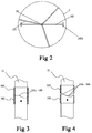
Fig. 2 is a top-viewed structure diagram of the silo de-bridging device according toEmbodiment 1 of the present invention; -
Fig. 3 is a schematic diagram of an end surface cam structure of a movable sleeve and a fixed sleeve according toEmbodiment 1 of the present invention, wherein end surface cam contours of the movable sleeve and the fixed sleeve are completely concave-convex fitted with each other; -
Fig. 4 is another schematic diagram of the end surface cam structure of the movable sleeve and the fixed sleeve according toEmbodiment 1 of the present invention, wherein the movable sleeve has moved axially after the movable sleeve and the fixed sleeve rotate relative to each other; -
Fig. 5 is a deployed diagram of a cam contour of an end surface cam structure of a de-bridging unit according toEmbodiment 1 of the present invention; -
Fig. 6 is a schematic diagram of a fitting condition of another end surface cam structure of the de-bridging unit according toEmbodiment 1 of the present invention; -
Fig. 7 is a schematic diagram of another fitting condition of the another end surface cam structure of the de-bridging unit according toEmbodiment 1 of the present invention; -
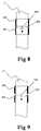
Fig. 8 is a schematic diagram of a fitting condition of still another end surface cam structure of the de-bridging unit according toEmbodiment 1 of the present invention; -
Fig. 9 is a schematic diagram of another fitting condition of the still another end surface cam structure of the de-bridging unit according toEmbodiment 1 of the present invention; -
Figs. 10-13 are schematic diagrams of several other end surface cam structures of the de-bridging unit according toEmbodiment 1 of the present invention; -
Fig. 14 is a structure diagram of a silo de-bridging device according toEmbodiment 2 of the present invention; -
Fig. 15 is a schematic diagram of a fitting condition of an end surface cam structure of a de-bridging unit according toEmbodiment 2 of the present invention; -
Fig. 16 is a schematic diagram of another fitting condition of the end surface cam structure of the de-bridging unit according toEmbodiment 2 of the present invention; -
Fig. 17 is a schematic diagram of a fitting condition of another end surface cam structure of the de-bridging unit according toEmbodiment 2 of the present invention; -
Fig. 18 is a schematic diagram of another fitting location of the another end surface cam structure of the de-bridging unit according toEmbodiment 2 of the present invention; -
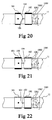
Figs. 19-22 are schematic diagrams of several other end surface cam structures of the de-bridging unit according toEmbodiment 2 of the present invention; -
Figs. 23-24 are schematic diagrams of two other modifications toEmbodiment 2 of the present invention. - The technical solutions of the embodiments of the present invention will be clearly and completely described as follows with reference to the drawings. Obviously, those described herein are just parts of the embodiments of the present invention rather than all the embodiments. Based on the embodiments of the present invention, any other embodiment obtained by a person skilled in the art without paying any creative effort shall fall within the protection scope of the present invention.
- As illustrated in
Figs. 1-22 , the present invention provides asilo de-bridging device 100 disposed in asilo 2. Thede-bridging device 100 includes arotary shaft 11 and at least onede-bridging unit 10 connected thereto, wherein therotary shaft 11 is rotatably supported in thesilo 2 and disposed in an axial direction of thesilo 2, having an input end connected to adrive mechanism 3 and driven by thedrive mechanism 3 to rotate. The at least onede-bridging unit 10 is connected to therotary shaft 11, and moveable up and down or rotatable along with the rotation of therotary shaft 11. Eachde-bridging unit 10 includes afixed sleeve 101, amovable sleeve 102 and at least onede-bridging arm 103. In which, thefixed sleeve 101 fixedly sleeves on therotary shaft 11 and being driven by therotary shaft 11 to rotate, and themovable sleeve 102 moveably sleeves on therotary shaft 11. One of two end surfaces of themovable sleeve 102 and thefixed sleeve 101 adjoining each other is formed as an endsurface cam contour 104, and the other is provided with anabutting member 105 moveable along the endsurface cam contour 104. The endsurface cam contour 104 coordinates with the abuttingmember 105 to constitute an end surface cam structure, so that themovable sleeve 102 is moveable to and fro in an axial direction of thesilo 2 when thefixed sleeve 101 and themovable sleeve 102 rotate relative to each other. Thede-bridging arm 103 has one end connected to themovable sleeve 102, and the other end extending to a position close to an inner wall of the silo in a radial direction of thesilo 2. - When the
silo 2 outputs a material to the outside, the fixedsleeve 101 of thede-bridging unit 10 is driven by therotary shaft 11 to rotate. When the material encounters a small resistance, no relative movement occurs between themovable sleeve 102 and the fixedsleeve 101, and themovable sleeve 102 drives thede-bridging arm 103 thereon to rotate along with the fixedsleeve 101. When the resistance to the material increases, the rotation of themovable sleeve 102 is hindered, a relative movement occurs between themovable sleeve 102 and the fixedsleeve 101, and themovable sleeve 102 moves to and fro in the axial direction under the action of the end surface cam structure between themovable sleeve 102 and the fixedsleeve 101, so as to drive thede-bridging arm 103 thereon to move in the axial direction of the silo. Thus in thesilo 2, thede-bridging arm 103 moves in the axial direction of the silo, and the material cannot be supported by the silo wall to form a bridged camber surface, thereby achieving an effective de-bridging of the silo. - In an optional example of the silo de-bridging device of the present invention, i.e.,
Embodiment 1 of the silo de-bridging device as illustrated inFigs. 1-13 , the axial direction of thesilo 2 may be a vertical direction, and correspondingly therotary shaft 11 is vertically disposed in thesilo 2. In the embodiment, themovable sleeve 102 is disposed above the fixedsleeve 101 in each de-bridging unit, so that the abuttingmember 105 of the end surface cam structure between themovable sleeve 102 and the fixedsleeve 101 always abuts against the endsurface cam contour 104 under the gravity, thereby enabling themovable sleeve 102 to be movable up and down along with the variation of the endsurface cam contour 104. Thus when themovable sleeve 102 and the fixedsleeve 101 rotate relative to each other, themovable sleeve 102 is movable up and down under the action of the end surface cam structure, thereby driving thede-bridging arm 103 connected to themovable sleeve 102 to move up and down to disturb the material in the silo up and down. Particularly, under the disturbance of thede-bridging arm 103, the material close to the inner wall of the silo cannot be supported by the inner wall of the silo and thus can not be bridged, so that the material can flow smoothly, and an effective de-bridging of the silo can be achieved. - As illustrated in
Figs. 14-22 , in another optional example of the silo de-bridging device of the present invention, i.e.,Embodiment 2 of the silo de-bridging device, eachde-bridging unit 10 is further provided with an elastic pushingdevice 106 that applies to the movable sleeve 102 a pushing force towards the fixedsleeve 101, so that through an elastic pushing from the elastic pushingdevice 106 to the movable sleeve, the abuttingmember 105 of the end surface cam structure between themovable sleeve 102 and the fixedsleeve 101 always abuts against the endsurface cam contour 104, and themovable sleeve 102 is movable to and fro in the axial direction of thesilo 2 along with the variation of the endsurface cam contour 104. Thus, when themovable sleeve 102 and the fixedsleeve 101 rotate relative to each other, themovable sleeve 102 can drive the connectedde-bridging arm 103 to move to and fro in the axial direction of thesilo 2 to axially disturb the material in thesilo 2. Particularly, under the axial disturbance of thede-bridging arm 103, the material close to the inner wall of the silo cannot be supported by the inner wall of the silo and thus can not be bridged, so that the material can flow smoothly, and an effective de-bridging of the silo can be achieved. - The
embodiment 2 of the present invention ensures abutment between the abutting member of the end surface cam structure and the end surface cam contour through the elastic pushing device, without utilizing the gravity, thus as illustrated inFigs. 14-22 , it can be applied in thesilo 2 whose axial direction is the horizontal direction, or a silo having its axial direction in a certain angle with the horizontal direction, e.g., a silo placed on a transport vehicle. In addition, thesilo de-bridging unit 10 having the elastic pushingdevice 106 may also be applied in a situation where the axial direction of thesilo 2 is the vertical direction, the material bears a very large resistance, and it is difficult for the abutting member of the end surface cam structure to always abut against the endsurface cam contour 104 under the gravity, as illustrated inFig. 23 . As illustrated inFig. 24 , thesilo de-bridging unit 10 having the elastic pushingdevice 106 may also be applied in an example where the axial direction of thesilo 2 is the vertical direction and themovable sleeve 102 is located below the fixedsleeve 101. - In a specific example of the elastic pushing
device 106 of thede-bridging unit 10 of the present invention, the elastic pushingdevice 106 may include a fixedretainer 1061 connected to therotary shaft 11, and anelastic member 1062 abutting between the fixedretainer 1061 and themovable sleeve 102. Theelastic member 1062 specifically may be a compression spring. - As illustrated in
Figs. 3-5 and15-16 , in an optional example of the end surface cam structure of the present invention, two end surfaces of themovable sleeve 102 and the fixedsleeve 101 adjoining each other are formed as end surface cam contours concave-convex fitted with each other, and a protrusion of one of the end surface cam contours is formed as the abuttingmember 105 of the end surface cam structure. - As illustrated in
Figs. 3-7 ,12-13 and15-16 , as an optional example of the endsurface cam contour 104 of the end surface cam structure of the present invention, the endsurface cam contour 104 may be a sine curve of at least one cycle after being deployed. The endsurface cam contour 104 using the sine curve enables the end surface cam structure formed between thefixed sleeve 101 and themovable sleeve 102 to move stably during the rotation of therotary shaft 11. The cycle of the sine curve actually reflects the concave-convex variations on the end surface cam structure, i.e., the number of times of the to and fro movements of themovable sleeve 102 in the axial direction once therotary shaft 11 rotates for a circle, and the number of the cycles may be selected according to the material condition, the silo size, etc. - As illustrated in
Figs. 9-11 and21-22 , as another optional example of the endsurface cam contour 104 of the end surface cam structure of the present invention, the endsurface cam contour 104 may include at least one V-groove contour. The structure of such endsurface cam contour 104 is easy to be machined with a low cost. - Although only a few examples of the end
surface cam contour 104 are given above, a person skilled in the art shall appreciate that the above examples are just exemplary, and the endsurface cam contour 104 is not limited thereto, provided that the endsurface cam contour 104 enables themovable sleeve 102 to be moveable to and fro in the axial direction of thesilo 2 when themovable sleeve 102 and the fixedsleeve 101 rotate relative to each other. The present invention may be implemented using many existing end surface cam contours, which are omitted herein. - As illustrated in
Figs. 6-9 ,11-12 and17-19 , as an optional example of the abuttingmember 105 of the end surface cam structure of the present invention, the abuttingmember 105 may be a contact protrusion protruding from the end surface of themovable sleeve 102 or the end surface of the fixedsleeve 101. An end of the contact protrusion abuts against the endsurface cam contour 104, so that themovable sleeve 102 moves to and fro in the axial direction of thesilo 2 along with the variation of the end surface cam contour, when themovable sleeve 102 rotates relative to the fixedsleeve 101. - As illustrated in
Figs. 10 ,13 and20-22 , in another optional example of the abuttingmember 105 of the end surface cam structure of the present invention, the abuttingmember 105 may be a roller structure, whose roller abuts against the endsurface cam contour 104, so that themovable sleeve 102 moves to and fro in the axial direction of thesilo 2 along with the variation of the end surface cam contour, when themovable sleeve 102 rotates relative to the fixedsleeve 101. - Although only a few examples of the abutting
member 105 are given above, a person skilled in the art shall appreciate that the above examples are just exemplary, and the abuttingmember 105 is not limited thereto, provided that the abuttingmember 105 abuts against the endsurface cam contour 104, so that the end surface cam structure enables themovable sleeve 102 to be moveable to and fro in the axial direction of thesilo 2 when themovable sleeve 102 and the fixedsleeve 101 rotate relative to each other. The specific structure of the abuttingmember 105 may not be limited. - In optional examples of the end surface cam structure of the present invention, as illustrated in
Figs. 6-10 ,17-20 and22 , the endsurface cam contour 104 may be formed on the end surface of the fixedsleeve 101, and the abuttingmember 105 may be formed on the end surface of themovable sleeve 102. Or, as illustrated inFigs. 11-13 and21 , the abuttingmember 105 abutting against the endsurface cam contour 104 may be formed on the end surface of the fixedsleeve 101, and the endsurface cam contour 104 may be formed on themovable sleeve 102. - As illustrated in
Figs. 1 and14 , an end of thede-bridging arm 103 close to the inner wall of the silo may be further provided with asub arm 1031 extending in the axial direction of thesilo 2, so as to improve the de-bridging effect. Upon the actual demand, thede-bridging arm 103 may be provided with a plurality ofsub arms 1031 extending in the axial direction, so as to improve the de-bridging effect. - In the present invention, in an optional example, the
de-bridging arm 103 may be fixedly connected to themovable sleeve 102. In another optional example, thede-bridging arm 103 may be hinged to themovable sleeve 102, and provided with a limiting structure for limiting the action angle of the de-bridging, e.g., limiting that thede-bridging arm 103 shall act in a range not more than 15 degrees. - For the
silo de-bridging device 100 having at least twode-bridging units 10, thesub arms 1031 at the ends of thede-bridging arms 103 of the neighboringde-bridging units 10 may be disposed alternatively in the radial direction of thesilo 2, so as to prevent friction between thesub arm 1031 and the inner wall of the silo due to the uneven wall surface of thesilo 2. - In the present invention, the number of the
de-bridging units 10 and the number of thede-bridging arms 103 in each de-bridging unit may be selected upon demand according to height, diameter and material condition of the silo. - As illustrated in
Figs. 1-2 , therotary shaft 11 of thesilo de-bridging device 100 of the present invention may be rotatably supported in thesilo 2 through a rotaryshaft centering frame 107. - The examples shown in
Figs. 1-24 just illustrate a few embodiments, and the present invention is not limited thereto. Upon demand, a person skilled in the art may obtain various different embodiments through permutation and combination of different features, such as the positions of the endsurface cam contour 104, the abuttingmember 105 of the end surface cam structure, and themovable sleeve 102 and the fixedsleeve 101 in the de-bridging device, the axial direction of thesilo 2, the arrangement of the elastic pushingdevice 106, which are omitted herein.
Claims (12)
- A silo de-bridging device (100), comprising:a rotary shaft (11) for being rotatably supported in a silo (2) and for being disposed in an axial direction of the silo (2), having an input end connected to a drive mechanism (3) and driven by the drive mechanism (3) to rotate; andat least one de-bridging unit (10) connected to the rotary shaft (11);wherein each de-bridging unit (10) comprising:a fixed sleeve (101) fixedly sleeving on the rotary shaft (11) and being driven by the rotary shaft (11) to rotate;a movable sleeve (102) moveably sleeving on the rotary shaft (11); and at least one de-bridging arm (103) having one end connected to the movable sleeve (102), and the other end arranged for extending to a position close to an inner wall of the silo (2) in a radial direction of the silo de-bridging device (100), characterised in that one of two end surfaces of the movable sleeve (102) and the fixed sleeve (101) adjoining each other is formed as an end surface cam contour (104), and the other is provided with an abutting member (105) that abuts against the end surface cam contour (104); the end surface cam contour (104) coordinates with the abutting member (105) to constitute an end surface cam structure, so that the movable sleeve (102) is moveable to and fro in the axial direction of the silo (2) when the fixed sleeve (101) and the movable sleeve (102) rotate relative to each other.
- The silo de-bridging device (100) according to claim 1, wherein the two end surfaces of the movable sleeve (102) and the fixed sleeve (101) adjoining each other are formed as end surface cam contours (104) concave-convex fitted with each other, and a protrusion of one of the end surface cam contours (104) is formed as the abutting member (105).
- The silo de-bridging device (100) according to claim 1, wherein the abutting member (105) is a contact protrusion protruding from the end surface of the movable sleeve (102) or the end surface of the fixed sleeve (101); or the abutting member (105) is a roller structure.
- The silo de-bridging device (100) according to claim 1, wherein the end surface cam contour (104) is a sine curve of at least one cycle after being deployed.
- The silo de-bridging device (100) according to claim 1, wherein the end surface cam contour (104) includes at least one V-groove contour.
- The silo de-bridging device (100) according to claim 1, wherein the axial direction of the silo (2) is a vertical direction, and in each de-bridging unit (10), the movable sleeve (102) is located above the fixed sleeve (101).
- The silo de-bridging device (100) according to claim 1, wherein each de-bridging unit (10) is further provided with an elastic pushing device (106) applying to the movable sleeve (102) a pushing force towards the fixed sleeve (101).
- The silo de-bridging device (100) according to claim 7, wherein the elastic pushing device (106) comprises a fixed retainer (1061) connected to the rotary shaft (11), and an elastic member (1062) abutting between the fixed retainer (1061) and the movable sleeve (102).
- The silo de-bridging device (100) according to claim 8, wherein the elastic member (1062) is a compression spring.
- The silo de-bridging device (100) according to claim 1, wherein the end of the de-bridging arm (103) for extending to a position close to the inner wall of the silo (2) is provided with a sub arm (1031) arranged for extending in the axial direction of the silo (2).
- The silo de-bridging device (100) according to claim 10, wherein the silo de-bridging device (100) has at least two de-bridging units (10), and the sub arms (1031) at the ends of the de-bridging arms (103) of the neighboring de-bridging units (10) are disposed alternatively in the radial direction of the silo de-bridging device (100).
- The silo de-bridging device (100) according to claim 1, wherein the rotary shaft (11) is arranged for being rotatably supported in the silo (2) through a rotary shaft centering frame (107).
Applications Claiming Priority (1)
| Application Number | Priority Date | Filing Date | Title |
|---|---|---|---|
| PCT/CN2010/080118 WO2012083531A1 (en) | 2010-12-22 | 2010-12-22 | Silo de-bridging device |
Publications (3)
| Publication Number | Publication Date |
|---|---|
| EP2657152A1 EP2657152A1 (en) | 2013-10-30 |
| EP2657152A4 EP2657152A4 (en) | 2014-07-02 |
| EP2657152B1 true EP2657152B1 (en) | 2016-03-30 |
Family
ID=46313031
Family Applications (1)
| Application Number | Title | Priority Date | Filing Date |
|---|---|---|---|
| EP10860967.8A Not-in-force EP2657152B1 (en) | 2010-12-22 | 2010-12-22 | Silo de-bridging device |
Country Status (6)
| Country | Link |
|---|---|
| US (1) | US9481511B2 (en) |
| EP (1) | EP2657152B1 (en) |
| AU (1) | AU2010366220B2 (en) |
| BR (1) | BR112013014721A2 (en) |
| CA (1) | CA2822154C (en) |
| WO (1) | WO2012083531A1 (en) |
Families Citing this family (7)
| Publication number | Priority date | Publication date | Assignee | Title |
|---|---|---|---|---|
| AU2010366220B2 (en) * | 2010-12-22 | 2015-09-24 | Hongyan Yu | Silo de-bridging device |
| CN104525015B (en) * | 2015-01-16 | 2016-07-06 | 河南省科学院能源研究所有限公司 | A kind of biomass silo material-stirring device |
| US11801993B1 (en) * | 2018-05-11 | 2023-10-31 | Abc Polymer Industries, Llc | Bulk material dispensing system |
| US11241664B1 (en) * | 2018-07-26 | 2022-02-08 | Feick Farms, LTD | Apparatus for starting the flow of a compacted material from a hopper trailer |
| CN111760505A (en) * | 2020-07-06 | 2020-10-13 | 孙建国 | Clinical medicine concentration regulator of department of anesthesia |
| US20240415093A1 (en) * | 2023-06-13 | 2024-12-19 | Deadfall Llc | Animal feeder system |
| EP4784279A1 (en) * | 2023-09-28 | 2026-08-05 | Battelle Memorial Institute | Laboratory equipment |
Family Cites Families (64)
| Publication number | Priority date | Publication date | Assignee | Title |
|---|---|---|---|---|
| US1851044A (en) * | 1931-02-28 | 1932-03-29 | Genovesi Gustave | Dispensing device |
| US2042739A (en) * | 1934-03-07 | 1936-06-02 | American La France And Foamite | Powder bin discharge structure |
| US2228421A (en) * | 1938-07-09 | 1941-01-14 | Vilter Mfg Co | Self-unloading bin |
| US2561258A (en) * | 1946-03-22 | 1951-07-17 | Cons Gas Electric Light And Po | Flexible rotary agitator for hoppers with variable eccentric mountings and spaced weights |
| US2532238A (en) * | 1946-04-10 | 1950-11-28 | Smith Corp A O | Mechanical unloading agitator for silos and the like |
| US2576620A (en) * | 1946-10-02 | 1951-11-27 | Smith Corp A O | Silo unloading device with means to dislodge silage for ready discharge |
| US2554109A (en) * | 1947-03-05 | 1951-05-22 | Anderson Co V D | Solvent extractor |
| US2609185A (en) * | 1949-07-04 | 1952-09-02 | F S Smidth & Co | Method and apparatus for increasing fluidity of material |
| US3038643A (en) * | 1958-02-03 | 1962-06-12 | Lely Nv C Van Der | Devices for spreading granular or powdery material |
| US3037713A (en) * | 1960-09-06 | 1962-06-05 | Frank T Carroll | Corn cob bin and disintegrator |
| US3048409A (en) * | 1961-01-31 | 1962-08-07 | Hawk Bilt Mfg Corp | Material unloading apparatus |
| US3138300A (en) * | 1961-09-15 | 1964-06-23 | Rint Inc | Bulk feed unloader |
| US3212672A (en) * | 1962-08-20 | 1965-10-19 | Elgin Softener Inc | Dry diatomaceous earth feeder |
| US3223290A (en) * | 1963-12-23 | 1965-12-14 | Schuld Leo Alois | Bottom discharge container with agitator |
| US3251512A (en) * | 1965-02-12 | 1966-05-17 | Baker Perkins Inc | Feeder means |
| AT309080B (en) * | 1965-12-20 | 1973-08-10 | Karl Fischer App Und Rohrleitu | Thin film evaporator for the polycondensation of bis (2-hydroxyethyl) terephthalate |
| US3392922A (en) * | 1965-12-28 | 1968-07-16 | Paul G. Lindgren | Flail-type material spreader with load opener |
| US3406914A (en) * | 1966-10-07 | 1968-10-22 | Int Harvester Co | Material unloader |
| DE1280157B (en) * | 1966-10-13 | 1968-10-10 | Weyhausen & Co Maschinenfabrik | Device for conveying powdery goods from a container |
| US3424350A (en) * | 1967-04-28 | 1969-01-28 | John H Herr | Bottom discharge for silo |
| US3556413A (en) * | 1968-07-05 | 1971-01-19 | Paul G Lindgren | Flail-type material spreader with load opener |
| US3602394A (en) * | 1969-06-27 | 1971-08-31 | Thomas F Mccune | Dispenser for silage additive |
| US3710986A (en) * | 1971-02-23 | 1973-01-16 | J Lepley | Safety enclosure for silos |
| US3710960A (en) * | 1971-08-12 | 1973-01-16 | Flying Dutchman | Bottom discharge means for silo |
| DE2143760A1 (en) * | 1971-09-01 | 1973-03-08 | Franz Bolick | DEVICE FOR EMPTYING HARD-FLOWING BAGS FROM STORAGE AND FLOW-THROUGH CONTAINERS |
| FR2207077B1 (en) * | 1972-11-22 | 1977-04-22 | Gouthiere Jean | |
| US3837507A (en) * | 1973-02-20 | 1974-09-24 | Flying Dutchman | Adjustable bottom discharge for silo |
| JPS534709B2 (en) * | 1973-04-27 | 1978-02-20 | ||
| US3907131A (en) * | 1973-08-06 | 1975-09-23 | Flying Dutchman | Bottom unloading means for silo |
| US3828946A (en) * | 1973-08-06 | 1974-08-13 | Flying Dutchman | Bottom unloading means for silo |
| US3828947A (en) * | 1973-08-17 | 1974-08-13 | Flying Dutchman | Material dislodging means for silo |
| US3942656A (en) * | 1973-08-17 | 1976-03-09 | Flying Dutchman, Inc. | Material dislodging means for silo |
| FR2335431A2 (en) * | 1975-12-16 | 1977-07-15 | Taupin Jean Paul | FLUIDIFICATION AND EXTRACTION DEVICE FOR MATERIAL IN A DIVIDED STATE |
| US4097001A (en) * | 1977-01-27 | 1978-06-27 | Sperry Rand Corporation | Detachable wear plate for a flail-type material spreader |
| SU793877A1 (en) | 1977-02-16 | 1981-01-07 | Московский Ордена Трудового Красногознамени Институт Химического Машино-Строения | Device for caving-in loose material bridges in hoppers |
| SU668859A1 (en) | 1978-02-15 | 1979-06-25 | Проектно-Конструкторское Бюро Министерства Сельского Строительства Белорусской Сср | Arrangement for caving-in semi-loose materials in hoppers |
| US4171165A (en) * | 1978-07-17 | 1979-10-16 | Diamond Insulation Industries, Inc. | Cellulose insulation storage bin with improved debridger |
| US4217996A (en) * | 1978-09-27 | 1980-08-19 | Good Lewis D | Material storage and feeding device |
| US4266901A (en) * | 1978-11-03 | 1981-05-12 | Wellons, Inc. | Storage bin having driven agitator |
| FR2451329A1 (en) * | 1979-03-13 | 1980-10-10 | Colin Michel | Centrifugal extractor for silo - has shaft with chains movable vertically to sweep walls clean of material |
| US4451004A (en) * | 1979-04-23 | 1984-05-29 | Sperry Corporation | Flail head |
| US4363428A (en) * | 1980-09-04 | 1982-12-14 | Brock Manufacturing, Inc. | Bulk bin feed delivery apparatus |
| US4620795A (en) * | 1983-01-12 | 1986-11-04 | The United States Of America As Represented By The United States Department Of Energy | Fluidizing device for solid particulates |
| US4571138A (en) * | 1984-04-09 | 1986-02-18 | David Farajun | Apparatus for silo clean out |
| JPS6186320A (en) * | 1984-10-01 | 1986-05-01 | Inshinaa Kogyo Kk | Powder material valvate feeding device |
| US4611921A (en) * | 1984-12-24 | 1986-09-16 | Texaco Inc. | Debridging apparatus |
| US4657402A (en) * | 1985-08-30 | 1987-04-14 | Construction Acton Ltee | Loosening of compacted material in a silo |
| US4957404A (en) * | 1989-07-24 | 1990-09-18 | Flying Dutchman, Inc. | Flail chain unloader for particulate material |
| FR2682940B1 (en) * | 1991-10-28 | 1994-02-04 | Symac | DEVICE FOR THE EXTRACTION OF A PRODUCT IN THE DIVIDED CONDITION AND FOR ITS VOLUMETRIC DOSING. |
| JPH06186320A (en) | 1992-03-28 | 1994-07-08 | Mitsui Constr Co Ltd | Survey device |
| US5411331A (en) * | 1993-06-01 | 1995-05-02 | Westinghouse Electric Corporation | Device for promoting gravity flow of non-free-flowing solids |
| US5516009A (en) * | 1994-03-04 | 1996-05-14 | Tecnetics Industries, Inc. | Stirrer for a hopper |
| DE19501179A1 (en) * | 1995-01-17 | 1996-07-18 | Zeppelin Schuettguttech Gmbh | Device for dosing bulk goods |
| US5931610A (en) * | 1997-05-19 | 1999-08-03 | Arr-Maz Products, L.P. | Fiber dispensing system |
| DE19828559C1 (en) * | 1998-06-26 | 2000-03-16 | Chronos Richardson Gmbh | Dosing device |
| CN1267625A (en) | 2000-04-11 | 2000-09-27 | 苟红侠 | Bin arch protector |
| CN2446094Y (en) * | 2000-09-11 | 2001-09-05 | 刘志平 | Granular podwer bunker with functions of breaking arch, blocking free and adjustable flow |
| JP2005169270A (en) | 2003-12-11 | 2005-06-30 | Eko Advance:Kk | Storage and discharge device |
| CN201010250Y (en) * | 2007-01-22 | 2008-01-23 | 刘凌云 | Barrel arch breaking device |
| CN201399844Y (en) | 2009-04-20 | 2010-02-10 | 吴汉民 | Hopper anti-clogging device |
| AU2010366220B2 (en) * | 2010-12-22 | 2015-09-24 | Hongyan Yu | Silo de-bridging device |
| CN201961725U (en) | 2010-12-22 | 2011-09-07 | 于红燕 | Storage bin arc-breaking device |
| CN105377725A (en) * | 2013-07-23 | 2016-03-02 | 车战斌 | Arch-breaking apparatus and material-distributing peak-regulating pool having the arch-breaking apparatus |
| CN104891056A (en) * | 2014-03-03 | 2015-09-09 | 车战斌 | Arch-breaking device and stock bin thereof |
-
2010
- 2010-12-22 AU AU2010366220A patent/AU2010366220B2/en not_active Ceased
- 2010-12-22 CA CA2822154A patent/CA2822154C/en not_active Expired - Fee Related
- 2010-12-22 EP EP10860967.8A patent/EP2657152B1/en not_active Not-in-force
- 2010-12-22 WO PCT/CN2010/080118 patent/WO2012083531A1/en not_active Ceased
- 2010-12-22 BR BR112013014721A patent/BR112013014721A2/en not_active Application Discontinuation
- 2010-12-22 US US13/995,388 patent/US9481511B2/en not_active Expired - Fee Related
Also Published As
| Publication number | Publication date |
|---|---|
| EP2657152A4 (en) | 2014-07-02 |
| EP2657152A1 (en) | 2013-10-30 |
| AU2010366220A1 (en) | 2013-07-11 |
| AU2010366220B2 (en) | 2015-09-24 |
| CA2822154A1 (en) | 2012-06-28 |
| US20130302117A1 (en) | 2013-11-14 |
| CA2822154C (en) | 2016-06-07 |
| WO2012083531A1 (en) | 2012-06-28 |
| BR112013014721A2 (en) | 2016-10-04 |
| US9481511B2 (en) | 2016-11-01 |
Similar Documents
| Publication | Publication Date | Title |
|---|---|---|
| US9481511B2 (en) | Silo de-bridging device including a sleeve structure having a cam contour surface | |
| EP3711867B1 (en) | Outpouring assembly | |
| US20180086008A1 (en) | Concrete delivery system | |
| WO2013036143A3 (en) | A torque device for oil field use and method of operation for same | |
| CN105819028A (en) | Deformable funnel for particle material filling | |
| BR112012030159A2 (en) | refinishing head for circular caps | |
| CN201961725U (en) | Storage bin arc-breaking device | |
| CN207570755U (en) | A kind of anti-impact device applied to balance in intermittent wind tunnel | |
| CN102530438B (en) | Arch breaking device for feed bin | |
| RU2011133827A (en) | DEVICE FOR EXTINGUISHING BENDING VIBRATIONS OF A ROTATING SHAFT | |
| JP2015045262A5 (en) | ||
| CN109573034A (en) | Jack and unmanned plane | |
| CN104682616A (en) | Mounting structure capable of adapting to mounting errors | |
| CN107128482B (en) | An anti-collision drone | |
| US20150001314A1 (en) | Spray cleaner head | |
| CN203765269U (en) | Rotating installation device | |
| CN203526001U (en) | Oil-paint coating and overturning device for wind-driven power-generation small blade | |
| CN203230186U (en) | Concrete floor spiral distributing device | |
| CN113391445A (en) | Security inspection equipment and scanning mirror driving device thereof | |
| CN103309277A (en) | Feeding device for fasteners | |
| CN211562752U (en) | Material barrel shaking equipment | |
| CN104787685B (en) | Tower crane device with liquid injecting heads and operation method for tower crane device | |
| CN104860208B (en) | The tower crane device of a kind of band limit switches and operation method thereof | |
| CN104076862B (en) | Rotation limit device | |
| CN104843592B (en) | A kind of tower crane device by pneumatic regulation and operation method thereof |
Legal Events
| Date | Code | Title | Description |
|---|---|---|---|
| PUAI | Public reference made under article 153(3) epc to a published international application that has entered the european phase |
Free format text: ORIGINAL CODE: 0009012 |
|
| 17P | Request for examination filed |
Effective date: 20130612 |
|
| AK | Designated contracting states |
Kind code of ref document: A1 Designated state(s): AL AT BE BG CH CY CZ DE DK EE ES FI FR GB GR HR HU IE IS IT LI LT LU LV MC MK MT NL NO PL PT RO RS SE SI SK SM TR |
|
| DAX | Request for extension of the european patent (deleted) | ||
| A4 | Supplementary search report drawn up and despatched |
Effective date: 20140604 |
|
| RIC1 | Information provided on ipc code assigned before grant |
Ipc: B65D 88/68 20060101AFI20140528BHEP |
|
| GRAP | Despatch of communication of intention to grant a patent |
Free format text: ORIGINAL CODE: EPIDOSNIGR1 |
|
| INTG | Intention to grant announced |
Effective date: 20150917 |
|
| GRAS | Grant fee paid |
Free format text: ORIGINAL CODE: EPIDOSNIGR3 |
|
| GRAA | (expected) grant |
Free format text: ORIGINAL CODE: 0009210 |
|
| AK | Designated contracting states |
Kind code of ref document: B1 Designated state(s): AL AT BE BG CH CY CZ DE DK EE ES FI FR GB GR HR HU IE IS IT LI LT LU LV MC MK MT NL NO PL PT RO RS SE SI SK SM TR |
|
| REG | Reference to a national code |
Ref country code: GB Ref legal event code: FG4D |
|
| REG | Reference to a national code |
Ref country code: CH Ref legal event code: EP |
|
| REG | Reference to a national code |
Ref country code: AT Ref legal event code: REF Ref document number: 785119 Country of ref document: AT Kind code of ref document: T Effective date: 20160415 |
|
| REG | Reference to a national code |
Ref country code: IE Ref legal event code: FG4D |
|
| REG | Reference to a national code |
Ref country code: DE Ref legal event code: R096 Ref document number: 602010031959 Country of ref document: DE |
|
| REG | Reference to a national code |
Ref country code: LT Ref legal event code: MG4D |
|
| PG25 | Lapsed in a contracting state [announced via postgrant information from national office to epo] |
Ref country code: NO Free format text: LAPSE BECAUSE OF FAILURE TO SUBMIT A TRANSLATION OF THE DESCRIPTION OR TO PAY THE FEE WITHIN THE PRESCRIBED TIME-LIMIT Effective date: 20160630 Ref country code: HR Free format text: LAPSE BECAUSE OF FAILURE TO SUBMIT A TRANSLATION OF THE DESCRIPTION OR TO PAY THE FEE WITHIN THE PRESCRIBED TIME-LIMIT Effective date: 20160330 Ref country code: GR Free format text: LAPSE BECAUSE OF FAILURE TO SUBMIT A TRANSLATION OF THE DESCRIPTION OR TO PAY THE FEE WITHIN THE PRESCRIBED TIME-LIMIT Effective date: 20160701 Ref country code: FI Free format text: LAPSE BECAUSE OF FAILURE TO SUBMIT A TRANSLATION OF THE DESCRIPTION OR TO PAY THE FEE WITHIN THE PRESCRIBED TIME-LIMIT Effective date: 20160330 |
|
| REG | Reference to a national code |
Ref country code: NL Ref legal event code: MP Effective date: 20160330 |
|
| REG | Reference to a national code |
Ref country code: AT Ref legal event code: MK05 Ref document number: 785119 Country of ref document: AT Kind code of ref document: T Effective date: 20160330 |
|
| PG25 | Lapsed in a contracting state [announced via postgrant information from national office to epo] |
Ref country code: SE Free format text: LAPSE BECAUSE OF FAILURE TO SUBMIT A TRANSLATION OF THE DESCRIPTION OR TO PAY THE FEE WITHIN THE PRESCRIBED TIME-LIMIT Effective date: 20160330 Ref country code: LT Free format text: LAPSE BECAUSE OF FAILURE TO SUBMIT A TRANSLATION OF THE DESCRIPTION OR TO PAY THE FEE WITHIN THE PRESCRIBED TIME-LIMIT Effective date: 20160330 Ref country code: RS Free format text: LAPSE BECAUSE OF FAILURE TO SUBMIT A TRANSLATION OF THE DESCRIPTION OR TO PAY THE FEE WITHIN THE PRESCRIBED TIME-LIMIT Effective date: 20160330 Ref country code: LV Free format text: LAPSE BECAUSE OF FAILURE TO SUBMIT A TRANSLATION OF THE DESCRIPTION OR TO PAY THE FEE WITHIN THE PRESCRIBED TIME-LIMIT Effective date: 20160330 |
|
| PG25 | Lapsed in a contracting state [announced via postgrant information from national office to epo] |
Ref country code: NL Free format text: LAPSE BECAUSE OF FAILURE TO SUBMIT A TRANSLATION OF THE DESCRIPTION OR TO PAY THE FEE WITHIN THE PRESCRIBED TIME-LIMIT Effective date: 20160330 |
|
| PG25 | Lapsed in a contracting state [announced via postgrant information from national office to epo] |
Ref country code: EE Free format text: LAPSE BECAUSE OF FAILURE TO SUBMIT A TRANSLATION OF THE DESCRIPTION OR TO PAY THE FEE WITHIN THE PRESCRIBED TIME-LIMIT Effective date: 20160330 Ref country code: IS Free format text: LAPSE BECAUSE OF FAILURE TO SUBMIT A TRANSLATION OF THE DESCRIPTION OR TO PAY THE FEE WITHIN THE PRESCRIBED TIME-LIMIT Effective date: 20160730 Ref country code: PL Free format text: LAPSE BECAUSE OF FAILURE TO SUBMIT A TRANSLATION OF THE DESCRIPTION OR TO PAY THE FEE WITHIN THE PRESCRIBED TIME-LIMIT Effective date: 20160330 |
|
| PG25 | Lapsed in a contracting state [announced via postgrant information from national office to epo] |
Ref country code: RO Free format text: LAPSE BECAUSE OF FAILURE TO SUBMIT A TRANSLATION OF THE DESCRIPTION OR TO PAY THE FEE WITHIN THE PRESCRIBED TIME-LIMIT Effective date: 20160330 Ref country code: AT Free format text: LAPSE BECAUSE OF FAILURE TO SUBMIT A TRANSLATION OF THE DESCRIPTION OR TO PAY THE FEE WITHIN THE PRESCRIBED TIME-LIMIT Effective date: 20160330 Ref country code: SM Free format text: LAPSE BECAUSE OF FAILURE TO SUBMIT A TRANSLATION OF THE DESCRIPTION OR TO PAY THE FEE WITHIN THE PRESCRIBED TIME-LIMIT Effective date: 20160330 Ref country code: CZ Free format text: LAPSE BECAUSE OF FAILURE TO SUBMIT A TRANSLATION OF THE DESCRIPTION OR TO PAY THE FEE WITHIN THE PRESCRIBED TIME-LIMIT Effective date: 20160330 Ref country code: ES Free format text: LAPSE BECAUSE OF FAILURE TO SUBMIT A TRANSLATION OF THE DESCRIPTION OR TO PAY THE FEE WITHIN THE PRESCRIBED TIME-LIMIT Effective date: 20160330 Ref country code: PT Free format text: LAPSE BECAUSE OF FAILURE TO SUBMIT A TRANSLATION OF THE DESCRIPTION OR TO PAY THE FEE WITHIN THE PRESCRIBED TIME-LIMIT Effective date: 20160801 Ref country code: SK Free format text: LAPSE BECAUSE OF FAILURE TO SUBMIT A TRANSLATION OF THE DESCRIPTION OR TO PAY THE FEE WITHIN THE PRESCRIBED TIME-LIMIT Effective date: 20160330 |
|
| PG25 | Lapsed in a contracting state [announced via postgrant information from national office to epo] |
Ref country code: BE Free format text: LAPSE BECAUSE OF FAILURE TO SUBMIT A TRANSLATION OF THE DESCRIPTION OR TO PAY THE FEE WITHIN THE PRESCRIBED TIME-LIMIT Effective date: 20160330 Ref country code: IT Free format text: LAPSE BECAUSE OF FAILURE TO SUBMIT A TRANSLATION OF THE DESCRIPTION OR TO PAY THE FEE WITHIN THE PRESCRIBED TIME-LIMIT Effective date: 20160330 |
|
| REG | Reference to a national code |
Ref country code: DE Ref legal event code: R097 Ref document number: 602010031959 Country of ref document: DE |
|
| PG25 | Lapsed in a contracting state [announced via postgrant information from national office to epo] |
Ref country code: DK Free format text: LAPSE BECAUSE OF FAILURE TO SUBMIT A TRANSLATION OF THE DESCRIPTION OR TO PAY THE FEE WITHIN THE PRESCRIBED TIME-LIMIT Effective date: 20160330 |
|
| PLBE | No opposition filed within time limit |
Free format text: ORIGINAL CODE: 0009261 |
|
| STAA | Information on the status of an ep patent application or granted ep patent |
Free format text: STATUS: NO OPPOSITION FILED WITHIN TIME LIMIT |
|
| 26N | No opposition filed |
Effective date: 20170103 |
|
| PG25 | Lapsed in a contracting state [announced via postgrant information from national office to epo] |
Ref country code: SI Free format text: LAPSE BECAUSE OF FAILURE TO SUBMIT A TRANSLATION OF THE DESCRIPTION OR TO PAY THE FEE WITHIN THE PRESCRIBED TIME-LIMIT Effective date: 20160330 |
|
| REG | Reference to a national code |
Ref country code: DE Ref legal event code: R119 Ref document number: 602010031959 Country of ref document: DE |
|
| REG | Reference to a national code |
Ref country code: CH Ref legal event code: PL |
|
| GBPC | Gb: european patent ceased through non-payment of renewal fee |
Effective date: 20161222 |
|
| PG25 | Lapsed in a contracting state [announced via postgrant information from national office to epo] |
Ref country code: MC Free format text: LAPSE BECAUSE OF FAILURE TO SUBMIT A TRANSLATION OF THE DESCRIPTION OR TO PAY THE FEE WITHIN THE PRESCRIBED TIME-LIMIT Effective date: 20160330 |
|
| REG | Reference to a national code |
Ref country code: FR Ref legal event code: ST Effective date: 20170831 |
|
| REG | Reference to a national code |
Ref country code: IE Ref legal event code: MM4A |
|
| PG25 | Lapsed in a contracting state [announced via postgrant information from national office to epo] |
Ref country code: LU Free format text: LAPSE BECAUSE OF NON-PAYMENT OF DUE FEES Effective date: 20161222 Ref country code: CH Free format text: LAPSE BECAUSE OF NON-PAYMENT OF DUE FEES Effective date: 20161231 Ref country code: FR Free format text: LAPSE BECAUSE OF NON-PAYMENT OF DUE FEES Effective date: 20170102 Ref country code: LI Free format text: LAPSE BECAUSE OF NON-PAYMENT OF DUE FEES Effective date: 20161231 |
|
| PG25 | Lapsed in a contracting state [announced via postgrant information from national office to epo] |
Ref country code: GB Free format text: LAPSE BECAUSE OF NON-PAYMENT OF DUE FEES Effective date: 20161222 Ref country code: DE Free format text: LAPSE BECAUSE OF NON-PAYMENT OF DUE FEES Effective date: 20170701 Ref country code: IE Free format text: LAPSE BECAUSE OF NON-PAYMENT OF DUE FEES Effective date: 20161222 |
|
| PG25 | Lapsed in a contracting state [announced via postgrant information from national office to epo] |
Ref country code: CY Free format text: LAPSE BECAUSE OF FAILURE TO SUBMIT A TRANSLATION OF THE DESCRIPTION OR TO PAY THE FEE WITHIN THE PRESCRIBED TIME-LIMIT Effective date: 20160330 Ref country code: HU Free format text: LAPSE BECAUSE OF FAILURE TO SUBMIT A TRANSLATION OF THE DESCRIPTION OR TO PAY THE FEE WITHIN THE PRESCRIBED TIME-LIMIT; INVALID AB INITIO Effective date: 20101222 |
|
| PG25 | Lapsed in a contracting state [announced via postgrant information from national office to epo] |
Ref country code: MK Free format text: LAPSE BECAUSE OF FAILURE TO SUBMIT A TRANSLATION OF THE DESCRIPTION OR TO PAY THE FEE WITHIN THE PRESCRIBED TIME-LIMIT Effective date: 20160330 |
|
| PG25 | Lapsed in a contracting state [announced via postgrant information from national office to epo] |
Ref country code: BG Free format text: LAPSE BECAUSE OF FAILURE TO SUBMIT A TRANSLATION OF THE DESCRIPTION OR TO PAY THE FEE WITHIN THE PRESCRIBED TIME-LIMIT Effective date: 20160330 |
|
| PG25 | Lapsed in a contracting state [announced via postgrant information from national office to epo] |
Ref country code: MT Free format text: LAPSE BECAUSE OF NON-PAYMENT OF DUE FEES Effective date: 20161222 |
|
| PG25 | Lapsed in a contracting state [announced via postgrant information from national office to epo] |
Ref country code: AL Free format text: LAPSE BECAUSE OF FAILURE TO SUBMIT A TRANSLATION OF THE DESCRIPTION OR TO PAY THE FEE WITHIN THE PRESCRIBED TIME-LIMIT Effective date: 20160330 Ref country code: TR Free format text: LAPSE BECAUSE OF FAILURE TO SUBMIT A TRANSLATION OF THE DESCRIPTION OR TO PAY THE FEE WITHIN THE PRESCRIBED TIME-LIMIT Effective date: 20160330 |