EP2656893A1 - Filterpatrone und Flüssigkeitsfilteranordnung - Google Patents
Filterpatrone und Flüssigkeitsfilteranordnung Download PDFInfo
- Publication number
- EP2656893A1 EP2656893A1 EP13156524.4A EP13156524A EP2656893A1 EP 2656893 A1 EP2656893 A1 EP 2656893A1 EP 13156524 A EP13156524 A EP 13156524A EP 2656893 A1 EP2656893 A1 EP 2656893A1
- Authority
- EP
- European Patent Office
- Prior art keywords
- filter cartridge
- section
- seal
- assembly
- filter
- Prior art date
- Legal status (The legal status is an assumption and is not a legal conclusion. Google has not performed a legal analysis and makes no representation as to the accuracy of the status listed.)
- Granted
Links
- 239000007788 liquid Substances 0.000 title claims abstract description 77
- 238000004891 communication Methods 0.000 claims description 5
- 238000007789 sealing Methods 0.000 description 8
- 238000001914 filtration Methods 0.000 description 7
- 239000002184 metal Substances 0.000 description 7
- 229910052751 metal Inorganic materials 0.000 description 7
- 238000009434 installation Methods 0.000 description 6
- 230000001154 acute effect Effects 0.000 description 4
- 239000004952 Polyamide Substances 0.000 description 3
- 238000010276 construction Methods 0.000 description 3
- 230000002093 peripheral effect Effects 0.000 description 3
- 229920002647 polyamide Polymers 0.000 description 3
- 239000000853 adhesive Substances 0.000 description 2
- 230000001070 adhesive effect Effects 0.000 description 2
- 230000000712 assembly Effects 0.000 description 2
- 238000000429 assembly Methods 0.000 description 2
- 230000004323 axial length Effects 0.000 description 2
- 239000012530 fluid Substances 0.000 description 2
- 239000011521 glass Substances 0.000 description 2
- 229920001903 high density polyethylene Polymers 0.000 description 2
- 239000000463 material Substances 0.000 description 2
- 238000012544 monitoring process Methods 0.000 description 2
- 239000004033 plastic Substances 0.000 description 2
- 229920003023 plastic Polymers 0.000 description 2
- 238000011144 upstream manufacturing Methods 0.000 description 2
- 229910052782 aluminium Inorganic materials 0.000 description 1
- XAGFODPZIPBFFR-UHFFFAOYSA-N aluminium Chemical compound [Al] XAGFODPZIPBFFR-UHFFFAOYSA-N 0.000 description 1
- 238000012512 characterization method Methods 0.000 description 1
- 230000008878 coupling Effects 0.000 description 1
- 238000010168 coupling process Methods 0.000 description 1
- 238000005859 coupling reaction Methods 0.000 description 1
- 238000010586 diagram Methods 0.000 description 1
- 230000003292 diminished effect Effects 0.000 description 1
- 239000000446 fuel Substances 0.000 description 1
- 230000002401 inhibitory effect Effects 0.000 description 1
- 238000003780 insertion Methods 0.000 description 1
- 230000037431 insertion Effects 0.000 description 1
- 230000000670 limiting effect Effects 0.000 description 1
- 238000005461 lubrication Methods 0.000 description 1
- 238000000034 method Methods 0.000 description 1
- 239000002991 molded plastic Substances 0.000 description 1
- 230000002829 reductive effect Effects 0.000 description 1
- 230000000717 retained effect Effects 0.000 description 1
- 238000012552 review Methods 0.000 description 1
- 239000007787 solid Substances 0.000 description 1
- 125000006850 spacer group Chemical group 0.000 description 1
Images


Classifications
-
- B—PERFORMING OPERATIONS; TRANSPORTING
- B01—PHYSICAL OR CHEMICAL PROCESSES OR APPARATUS IN GENERAL
- B01D—SEPARATION
- B01D29/00—Filters with filtering elements stationary during filtration, e.g. pressure or suction filters, not covered by groups B01D24/00 - B01D27/00; Filtering elements therefor
- B01D29/11—Filters with filtering elements stationary during filtration, e.g. pressure or suction filters, not covered by groups B01D24/00 - B01D27/00; Filtering elements therefor with bag, cage, hose, tube, sleeve or like filtering elements
- B01D29/13—Supported filter elements
- B01D29/15—Supported filter elements arranged for inward flow filtration
- B01D29/21—Supported filter elements arranged for inward flow filtration with corrugated, folded or wound sheets
-
- B—PERFORMING OPERATIONS; TRANSPORTING
- B01—PHYSICAL OR CHEMICAL PROCESSES OR APPARATUS IN GENERAL
- B01D—SEPARATION
- B01D29/00—Filters with filtering elements stationary during filtration, e.g. pressure or suction filters, not covered by groups B01D24/00 - B01D27/00; Filtering elements therefor
- B01D29/50—Filters with filtering elements stationary during filtration, e.g. pressure or suction filters, not covered by groups B01D24/00 - B01D27/00; Filtering elements therefor with multiple filtering elements, characterised by their mutual disposition
- B01D29/52—Filters with filtering elements stationary during filtration, e.g. pressure or suction filters, not covered by groups B01D24/00 - B01D27/00; Filtering elements therefor with multiple filtering elements, characterised by their mutual disposition in parallel connection
- B01D29/54—Filters with filtering elements stationary during filtration, e.g. pressure or suction filters, not covered by groups B01D24/00 - B01D27/00; Filtering elements therefor with multiple filtering elements, characterised by their mutual disposition in parallel connection arranged concentrically or coaxially
-
- B—PERFORMING OPERATIONS; TRANSPORTING
- B01—PHYSICAL OR CHEMICAL PROCESSES OR APPARATUS IN GENERAL
- B01D—SEPARATION
- B01D29/00—Filters with filtering elements stationary during filtration, e.g. pressure or suction filters, not covered by groups B01D24/00 - B01D27/00; Filtering elements therefor
- B01D29/96—Filters with filtering elements stationary during filtration, e.g. pressure or suction filters, not covered by groups B01D24/00 - B01D27/00; Filtering elements therefor in which the filtering elements are moved between filtering operations; Particular measures for removing or replacing the filtering elements; Transport systems for filters
-
- B—PERFORMING OPERATIONS; TRANSPORTING
- B01—PHYSICAL OR CHEMICAL PROCESSES OR APPARATUS IN GENERAL
- B01D—SEPARATION
- B01D35/00—Filtering devices having features not specifically covered by groups B01D24/00 - B01D33/00, or for applications not specifically covered by groups B01D24/00 - B01D33/00; Auxiliary devices for filtration; Filter housing constructions
- B01D35/02—Filters adapted for location in special places, e.g. pipe-lines, pumps, stop-cocks
- B01D35/027—Filters adapted for location in special places, e.g. pipe-lines, pumps, stop-cocks rigidly mounted in or on tanks or reservoirs
- B01D35/0276—Filtering elements with a vertical rotation or symmetry axis mounted on tanks or reservoirs
-
- B—PERFORMING OPERATIONS; TRANSPORTING
- B01—PHYSICAL OR CHEMICAL PROCESSES OR APPARATUS IN GENERAL
- B01D—SEPARATION
- B01D35/00—Filtering devices having features not specifically covered by groups B01D24/00 - B01D33/00, or for applications not specifically covered by groups B01D24/00 - B01D33/00; Auxiliary devices for filtration; Filter housing constructions
- B01D35/14—Safety devices specially adapted for filtration; Devices for indicating clogging
- B01D35/147—Bypass or safety valves
-
- B—PERFORMING OPERATIONS; TRANSPORTING
- B01—PHYSICAL OR CHEMICAL PROCESSES OR APPARATUS IN GENERAL
- B01D—SEPARATION
- B01D35/00—Filtering devices having features not specifically covered by groups B01D24/00 - B01D33/00, or for applications not specifically covered by groups B01D24/00 - B01D33/00; Auxiliary devices for filtration; Filter housing constructions
- B01D35/14—Safety devices specially adapted for filtration; Devices for indicating clogging
- B01D35/153—Anti-leakage or anti-return valves
-
- B—PERFORMING OPERATIONS; TRANSPORTING
- B01—PHYSICAL OR CHEMICAL PROCESSES OR APPARATUS IN GENERAL
- B01D—SEPARATION
- B01D2201/00—Details relating to filtering apparatus
- B01D2201/04—Supports for the filtering elements
- B01D2201/0415—Details of supporting structures
-
- B—PERFORMING OPERATIONS; TRANSPORTING
- B01—PHYSICAL OR CHEMICAL PROCESSES OR APPARATUS IN GENERAL
- B01D—SEPARATION
- B01D2201/00—Details relating to filtering apparatus
- B01D2201/34—Seals or gaskets for filtering elements
-
- B—PERFORMING OPERATIONS; TRANSPORTING
- B01—PHYSICAL OR CHEMICAL PROCESSES OR APPARATUS IN GENERAL
- B01D—SEPARATION
- B01D2201/00—Details relating to filtering apparatus
- B01D2201/40—Special measures for connecting different parts of the filter
- B01D2201/4046—Means for avoiding false mounting of different parts
Definitions
- the invention relates generally to liquid filters and methods.
- the example embodiment described is an in-tank filter assembly, for use, for example, in hydraulic systems.
- Liquid filters are employed in a variety of applications, including, for example, hydraulic systems, fuel systems and engine lubrication systems.
- liquid filters which accommodate downstream components, are of concern. Particularly, it is of concern to prevent cavitation of pumps and other equipment downstream from liquid filters. Conditions such as cold starts, flow surges or occluded elements can result in damaged downstream components.
- a filter cartridge for use with a liquid filter assembly includes: a primary filter cartridge section; a bypass filter cartridge section; a first end cap positioned between the primary filter cartridge section and the bypass filter cartridge section; a seal surrounded by the media of the bypass filter cartridge section; and a second end cap positioned on an opposite end of the primary filter cartridge section from the first end cap.
- the seal support includes a first inner seal member defining a first inwardly directed seal. The first inwardly directed seal is positioned in a slanted seal plane non-orthogonal to a central axis of the bypass filter cartridge section.
- the reference numeral 1, Fig. 1 generally indicates a liquid filter arrangement or assembly according to this aspect of the present disclosure.
- the liquid filter assembly 1 includes a housing 3 comprising: a filter head 4 having a body 4a and a removable top or cover 5; and, a side wall 7, which in use, extends (depends downwardly) from filter head 4.
- the housing 3 defines an internal volume 8, in which: selected internal componentry as defined is contained; and, certain filtering and flow operations occur.
- the liquid filter assembly 1 further includes a suction filter assembly 10.
- top “above,” and, “below,” are meant to refer to the assembly 1, when oriented for normal use, i.e., when in the orientation of Fig. 1 .
- the liquid filter assembly 1 includes, operably positioned therein, a serviceable (i.e., removable and replaceable) filter cartridge arrangement 15, Figs. 7 and 8 .
- a serviceable filter cartridge arrangement 15, Figs. 7 and 8 optionally includes two filter sections or components namely: a primary (upper) filter cartridge or cartridge section 17; and, a bypass (lower) filter cartridge or cartridge section 18.
- the primary filter cartridge section 17 and bypass filter cartridge section 18 are typically secured to one another, and are removed and serviced as an integral unit.
- the primary filter cartridge or cartridge section 17 is not required to be non-separably attached to the bypass filter cartridge or cartridge section 18.
- the arrangement depicted, in which the two are typically permanently secured to one another is convenient and typical.
- the typical serviceable filter cartridge assembly 15, Figs. 7 and 8 further includes, as described below, an end cap and seal arrangement 20 (sometimes referred to as the upper or second end cap), which provides for a preferred mounting and sealing of the serviceable filter cartridge arrangement 15 to the filter head 4 within the liquid filter arrangement 1.
- an end cap and seal arrangement 20 (sometimes referred to as the upper or second end cap), which provides for a preferred mounting and sealing of the serviceable filter cartridge arrangement 15 to the filter head 4 within the liquid filter arrangement 1.
- the preferred liquid filter assembly 1 depicted includes a bypass valve assembly 25, Figs. 1 , 5 and 13 .
- the filter head 4 generally includes a body 4a having an inlet or inlet arrangement 30 and an outlet or outlet arrangement 31.
- the liquid flow inlet arrangement 30 will sometimes be referred to as a circulation loop liquid flow inlet arrangement, since it is an inlet arrangement to the filter head 4 of liquid from a liquid circulation loop in which the liquid filtered by assembly 1 circulates to perform its function.
- the outlet arrangement 31 will sometimes be referred to as a circulation loop liquid flow outlet arrangement, since it is an outlet for filtered liquid, from the filter head 4 and thus the assembly 1, for liquid to be directed into a liquid circulation loop to perform its function.
- the filter head 4 includes, for the inlet arrangement 30, two inlets 30x, 30y; and, for the outlet arrangement 31, two outlets 31x, 31y, although alternatives are possible.
- This allows assembly 1 to be operated with two circulation loops, for filtered liquid. If the assembly 1 is to be used with only a single circulation loop, an appropriate one of inlets 30x, 30y and an appropriate one of outlets 31x, 31y, can optionally be closed or capped.
- volume 33 is an "unfiltered liquid volume,” since the liquid received therein, will generally be received directly from a circulation loop, and will be unfiltered and require filtering.
- the liquid In normal operation, from the unfiltered liquid volume 33, the liquid is passed through the primary filter cartridge 17 to its interior 35. (This would be a filtering flow.) From the central volume 35 the liquid can pass out of the filter cartridge 15 in a direction of arrow 40 to outlet arrangement 31; and, outwardly from the assembly 1. (This latter flow from volume 35 through outlet arrangement 31 is a non-filtering flow.)
- assembly 1, Fig. 1 does not include a central standpipe projecting into primary cartridge section 17.
- a central structure 300 which is present, but typically does not extend into section 17 is discussed below.
- a flow path indicated by arrow 49, from region 35, would be a liquid flow exit from assembly 1 into a tank reservoir; a tank reservoir not shown in Fig. 1 .
- the liquid filter assembly 1 would be an in-tank assembly in accord with the principles described in PCT Publication WO 05/63358 and would be mounted on a reservoir tank with suction filter assembly 10 submerged in the tank or tank reservoir.
- a mounting flange for attachment to a tank is shown at 4f.
- flow/pressure regulation valve arrangement 47 is conveniently positioned below the suction filter assembly 10 to control flow through outlet 42, as described in detail below.
- the directionally biased flow (valve) arrangement 52 allows for entrance of liquid into region 35, but inhibits liquid flow in an opposite direction, so as not to override or disable a proper bypass operation of flow/pressure regulation valve arrangement 47.
- the preferred directionally biased flow (valve) arrangement 52 depicted is a non-helical spring valve arrangement 52a, referenced below. It is noted that for the embodiment depicted in Fig. 1 , the non-helical spring valve arrangement 52 surrounds the filter 51, although alternatives are possible.
- bypass filter arrangement 55 Fig. 1
- the bypass filter arrangement 55 includes bypass filter section 18 and bypass control valve arrangement 25.
- the bypass control valve arrangement 25 is configured to open, to allow liquid flow through bypass filter 18 and into central volume 35, as a filtering flow but without passage through filter media 17a in primary filter cartridge 17. This flow can then proceed, in the direction of arrow 40, Fig. 1 , through outlet arrangement 31, or alternatively into the tank reservoir by passage through outlet 42 and from assembly 1.
- filter head 4 will be a cast member, for example made from cast aluminum or other material.
- Cover 5 is secured by bolts 6, Fig. 1 , to the filter head 4, to close service aperture 5a, with spaced, radial, seals provided by o-rings 60.
- the cover 5 includes handle 61 and extensions 61a, for bolts 6.
- An optional bleed valve assembly 56, Fig. 6 can be provided, as depicted in PCT Publication WO 05/63358 .
- the cover 5 includes, positioned internally and centrally, a stem 62, configured to project into a central volume 4b of filter head 4.
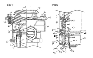
- the filter cartridge 15 is sealed to a lower, solid, inside portion 62i of stem 62 by seal 20a on stem 20b, Fig. 4 .
- stem 20b, on cartridge 15 projects inside of stem 62, on cover 5.
- the seal, 20a separates the filter head 4 into an unfiltered region 4x and a filtered region 4y.
- spring 63 is positioned inside the stem 62, Fig. 1 , to ensure that the serviceable filter cartridge 15 is retained in extension into the housing 3, at an appropriate position and to ensure that the cartridge 15 cannot be moved out of its operational (sealed) position, unless cover 5 is removed.
- the sidewall portion 7 of the liquid filter assembly 1 depicted, Fig. 1 is separable from the filter head 4.
- the body 4a of filter head 4, Fig. 1 includes an aperture 64 therein positioned on opposite side or direction of the filter head body 4a from the service aperture 5 a and cover 5.
- the sidewall section 7, projects through, and outwardly from (in use downwardly from), the aperture 64.
- the sidewall section 7 can be provided with a wire handle (not shown) which can be rotated down (analogously to sidewall section 607, Figs. 17 and 18 of PCT Publication WO 05/63358 ).
- the sidewall section 7 has shoulder 65 (at an upper end in use) and an opposite (in use bottom) end 66.
- the side wall 7 is sized such that, during assembly, when the top 5 is removed from body 4a, Fig. 1 , the side wall 7 can be lowered into the housing 3 through the opening 5a provided by the absence of the cover 5, until the shoulder 65 engages shoulder 67 in the filter head 4.
- Shoulder 65, Fig. 1 is provided with a seal member 68, to provide for a seal at this location.
- the serviceable filter cartridge 15 includes the second (upper in use) end cap and seal arrangement 20, referenced above.
- the second end cap and seal arrangement 20, for the particular embodiment depicted, is mounted on an end (in use upper end 70) of the primary filter cartridge 17.
- the second end cap and seal arrangement 20 includes an end cap portion 71 which, for example, can be a molded member secured (i.e., potted) to the primary filter cartridge 17.
- the end cap portion 71 includes a central aperture 72, for passage there through of liquid (from region 35) to be directed in the direction of arrow 40 ( Fig. 1 ) to circulation loop outlet arrangement 31.
- the end cap portion 71 includes axial projection 20b.
- the axial projection 20b is tubular with an outer surface and projects in an opposite direction, with respect to end cap portion 71, from primary cartridge media 17a.
- the projection 72a is configured to project into projection 62, Fig. 1 , with sealing by a housing seal member such as o-ring 20a, as previously mentioned.
- the o-ring or seal 20a then, is mounted on an outside surface of, and surrounds, projection 20b.
- a handle arrangement 73 is depicted mounted on end cap portion 71.
- the handle arrangement is collapsible, see Fig. 7 , during installation.
- the handle 73 can be used, for example, to raise cartridge 15 from its installed position Fig. 1 , when cover 5 is removed.
- the end cap 71 can be molded from a variety of moldable plastic materials, for example a polyamide (PA).
- a polyamide PA
- a glass filled polyamide 15-30% glass filled by wt.
- It can also be formed as a metal piece.
- end cap 20 includes a shield projection 71a thereon.
- the shield projection 71a projects downwardly along an outside 17b of media 17a in cartridge 17 generally a length of extension far enough to extend to a point at or below a lower most extent of each of inlet arrangement 30 and outlet arrangement 31, Fig. 1 . This will inhibit fluid entering inlet arrangement 30 from directly impinging upon the media 17a at this location.
- a central support or inner support 85 can be positioned along an inside 17c of the pleated media 17, for support.
- a perforated metal liner, or expanded metal liner, can be used, for the inner support 85. If a metal-free or reduced metal configuration is desired for the serviceable cartridge 15, a perforated or porous plastic liner can be used.
- a preferred coiled metal strip, perforated or louvered, with an edge coupling is depicted as used for liner 85.
- the media 17a can be a pleated media contained within a pleated mesh or similar structure, with pleats extending between the opposite end caps.
- the mesh may comprise a metal wire mesh or a plastic mesh, as preferred for a selected application.
- the axial length of the media 17a of the primary filter media section 17, will be at least 3 times (typically at least 4 times) the axial length of the bypass filter media 18a, although alternatives are possible.
- the primary filter cartridge 17 may be desirable to provide the primary filter cartridge 17 with an upstream outer liner such as a porous metal or plastic liner; or, a liner/valve construction, in accord with the descriptions of PCT Publication WO 04/000436 published December 31, 2003 , incorporated herein by reference.
- an upstream outer liner such as a porous metal or plastic liner; or, a liner/valve construction, in accord with the descriptions of PCT Publication WO 04/000436 published December 31, 2003 , incorporated herein by reference.
- the primary filter section 17 is secured to first end cap 88.
- End cap 88 is open, having a central aperture 89.
- bypass filter section or arrangement 18 comprising media 18a secured in extension between end cap 88 and a lower, opposite, third end cap 90.
- the primary filter cartridge section 17, and in particular the media 17a can be characterized as circumscribing a primary filter section central axis 17x; and, the bypass filter section 18, and in particular the media 18a, can be characterized as circumscribing a bypass filter section central axis 18x.
- the axes 17x, 18x are colinear; and, each of the media extensions 17a, 18a, is generally circular in cross-sectional definition. Alternatives from this are possible with the principles as described herein.
- Media 18a bypass arrangement 18 is positioned surrounding a seal support 91.
- the seal support 91 is secured to, and between end cap 88 and end cap 90.
- Seal support 91 can be secured in place with adhesive.
- Undercuts 91s, Fig. 20 can be used to receive adhesive and facilitate adhesion in place.
- Inner seal 92 in the example shown comprising an o-ring, is depicted positioned on an upwardly directed shelf or shoulder 91a of seal support ring 91 at a location between shoulder 91a and a downwardly, axially, projecting portion 88a on end cap 88.
- Portion 88a generally comprises a downwardly projecting inside ring on end cap 88 extending in a direction opposite media pack 17a and primary filter cartridge section 17.
- Seal support 91 is provided with a second inner seal 93, in the example shown as an o-ring, at a second, lower, end 91x positioned between shoulder 91b and end cap 90.
- a projected internal seal size defined by the upper ring 92 is smaller than the projected internal size of the internal seal definition provided by seal 93. That is, if projected into a plane, an inner circle defined by seal member 92 is smaller than the circle defined to by the interior seal 93. As a result, when the cartridge 15 is installed, seal member 93 can be easily slid past a seal surface for seal member 92, to sealingly engage a larger outer diameter surface for sealing. Alternately stated, a region of a structure around which seal 92 extends, has a small lip, then a region of the same structure around which seal 93 extends. This is discussed further below, in connection with Fig. 9 .
- perforated portion 95 of media/seal support ring 91 Located between the seal rings or o-rings 92, 93, is provided perforated portion 95 of media/seal support ring 91.
- Seal support ring 91 is depicted in more detail, in Figs. 17-20 . Referring to Fig. 17 , a top perspective view of seal support ring 91 is depicted.
- the seal support ring 91 includes: upper o-ring support shoulder 91 a; outer peripheral perforated sidewall region 95; and, internal, lower, downwardly directed, shoulder 91b, Fig. 19 .
- the ring 91 also includes an upper axial end surface 96, positioned to abut a portion of end cap 88, Fig. 8 , during assembly.
- the ring 91 includes an upper gap or slot portion 97, discussed further below.
- a downwardly, axially, directed, locator or key slot 99 in sidewall 98, which includes perforated ring 95, is also included a downwardly, axially, directed, locator or key slot 99.
- the key slot 99 extend completely through sidewall region 95 of ring 91.
- key slot 99 which communicates with an inner portion 91i of ring 91, it does not extend through to outer portion 91o, see Fig. 20 .
- the key slot 99 as discussed below, is configured to slidably engage and receive therein a projection on a structural portion of assembly 1, when the filter cartridge 15 is installed. This will be discussed below in connection with elongate locator or key projection 212, Fig. 9 .
- sidewall 98 comprises a plurality of vertically spaced rings 98a, with perforated portions 95 comprising flow regions therebetween, and between vertical spacers 98b.
- ring member 91 would be a molded plastic component, although alternatives are possible.
- Fig. 18 a side elevational view taken toward downwardly directed upper gap or slot 97 is shown.
- Fig. 19 a cross-sectional view taken along line 19-19, Fig. 17 , is depicted.
- key slot 99 is viewable, as well as seal shoulder 91a.
- Fig. 20 a cross-sectional view taken along 20-20, Fig. 17 , is depicted.
- shoulders 91a, 91b are readily viewable.
- shoulder 91a is planar and sits in a plane slanted from horizontal, i.e., in a plane extending at an angle x, Fig. 20 .
- the angle x is an acute angle from horizontal, when ring 91 is positioned with surface 96 pointed upwardly and shoulder 91b pointed downwardly.
- the angle x generally extends at an angle x of at least 4°, typically not more than 30° (typically 4° - 20° inclusive), and often within the range of 7° - 15°.
- o-ring 92 is positioned at an angle corresponding to angle x.
- ring 91 can be said to have a central vertical axis extending thereto, generally corresponding to axis 18x, Fig. 8 .
- the plane of shoulder 91a is generally non-orthogonal to axis 18x, i.e., does not extend at 90° thereto. Further, the plane of shoulder 91a, generally extends at an acute angle x relative to a plane that would be orthogonal to central axis 18x.
- seal member 92 will extend over a key to which key slot 99 engages, and underneath gap 97.
- the seal member 92 will also extend underneath a gap 213, Fig. 12 , in a frame piece 200 to which the seal member 92 seals. This is discussed below.
- cover 5 would be removed, and the serviceable filter cartridge 75, comprising the primary filter cartridge 17 and the bypass filter 18, would be operably installed in place of a removed cartridge. Finally, cover 5 would be positioned in place.
- the bypass valve assembly 25 Proper operation of the bypass filter 18, is controlled by the bypass valve assembly 25.
- the bypass valve assembly 25 comprises a valve member 100; in this instance a tubular valve member 101 slidably positioned within seat 102 between biasing member 105 (in this instance spring 105a) and stop 106. Sufficient fluid pressure through ring 91 and against region 107 will cause the bypass valve 25 to open.
- the valve member 100 and spring 105a are mounted within internal valve frame piece 200.
- the valve frame piece 200 includes and defines seat 102.
- valve member 100 of the bypass filter assembly 25 is moveable between two positions: a first, closed, sealed position as depicted in Fig. 5 ; and, a second, open position.
- first, sealed, closed position the tubular valve member 101 is biased against seat 102 by the biasing member 105.
- second, opened, orientation sufficient pressure against the tubular valve member 101, causes the tubular valve member 101 to bias against the biasing member 105, overcoming a closing force of the biasing member 105, to unseat the tubular valve member 101 from the seat 102.
- valve frame piece 200 mounted on housing 3, supports: bypass valve assembly 25; suction filter assembly 10; and, flow/regulation valve assembly 47.
- valve frame piece 200 is a sub-component of a valve sub-assembly 200x, Fig. 13 .
- the valve sub-assembly 200x supports: the bypass valve assembly 25; the tank outlet flow regulation valve assembly 47; and, provides mounting and sealing engagement for: an installed filter cartridge 15; installation of the valve sub-assembly 200x in the housing 4; and, mounting of the suction filter assembly 10.
- valve frame piece 200 is depicted in top perspective view and generally in an orientation similar to that it would have when installed on the housing 3 of the arrangement 1 of Fig. 1 .
- piece 200 is depicted in side elevational view.
- Fig. 11 a cross-sectional view along line 11-11, Fig. 10 is provided.
- frame piece 200 is viewed in the valve sub-assembly 200x, discussed below.
- frame piece 200 is tubular with a central conduit 200c extending axially completely therethrough.
- Frame piece 200 has opposite open (axial) ends, comprising upper end 201 and lower end 202.
- valve frame piece 200 Spaced between ends 201 and 202, is provided an outwardly projecting radial ring section 205 defining peripheral seal support member 205a, with an outer annular, peripheral, seal groove 206 therein.
- a seal member such as an o-ring 208, Fig. 5 , is typically positioned within groove 206, for sealing against lower sidewall section 7x.
- end 66 of the sidewall 7 would be pinched around projection 205, as shown, to help secure frame piece 200 in position.
- Seal support member 205a generally separates the frame piece 200 into two tubular sections, 200a and 200b, Fig. 9 ; section 200a corresponding to projection 300, Fig. 1 .
- first or upper section 200a generally projects axially into an interior of side wall 7, when frame piece 200 is mounted; and, second or lower section 200b generally projects axially outwardly (downwardly) from side wall 7 when frame piece 200 is mounted.
- valve frame piece 200 adjacent first or upper end 201, upper, first, section 200a of valve frame piece 200 defines, upper, outer, seal surface 210 for seal member 92.
- the seal surface 210 is sized and configured to be received within ring 91, Fig. 5 , during use; with sealing between valve frame piece 200 and end cap ring 91 being provided by o-ring 92, Figs. 5 and 8 . Again, sealing is preferably along outside surface 210, although alternate configurations are possible.
- upper section 220a of valve frame piece 200 includes lower seal region 211.
- Lower seal region 211 is configured to seal engage at seal 93, Fig. 5 . It is noted that seal region 211 has a slightly larger outer size (diameter), than does seal region 210.
- section 200a of frame piece 200 includes, along an outer surface thereof: key or locator projection 212; and, in communication with upper end 201, gap 213.
- Projection 212 is spaced from end 201 and extends away (downwardly) from region 210 (and end 201) toward central region 205.
- Projection 212 is sized in position to be received within key slot 99, when cartridge 15 is pushed over end 201, in particular when ring 91 is pushed over end 200a.
- a slanted seal supported by shoulder 91a, and resulting from o-ring 92, will pass above projection 212 and below gap 213, along side wall surface 210 of region 200a, to form the slanted seal engagement between cartridge 15 and frame piece 200.
- Projection 212 engages key slot 99, and provides for appropriate radial orientation between the cartridge 15 and the valve frame piece 200, during installation.
- the cartridge 15 would be rotated with downward pushing, until a proper orientation of engagement between projection 212 and slot 99 occurs, at which time axial insertion (cartridge 15 lowering into a seal orientation) occurs.
- axial insertion carrier 15 lowering into a seal orientation
- interior volume 220 of internal frame piece 200 is sized for receipt of components of the bypass valve assembly 25 therein to form a portion of valve sub-assembly 200x.
- valve member 101 and biasing member 105a are shown positioned in interior 220.
- the biasing member or spring 105a is seated at seat 221, Fig. 13 , and extends upwardly.
- the valve member 101 is slidably received between the spring 105 and stop or seat 106.
- valve member 101 and shoulder 106 i.e., against the spring force of spring 105a, opening the valve assembly 25 to liquid flow pass from exterior through into interior region 201i. From here, for example, the liquid flow can be through interior 35, in the direction of arrow 40 to outlet flow arrangement 31 as discussed above.
- seal 101x within receiver 101r provides seal engagement between valve member 101 and upper section 200a of frame piece 200, along interior 201i, below openings 200s.
- Stop 221 comprises a portion of a spoked frame piece 222, see Figs. 13-16 , secured within interior 220 above snap ring 223, and biased in place, in part, by spring 105a.
- piece 22 includes a central projection member 224 with a vertical channel 226 running therethrough.
- inner spring 230 is shown extending between snap ring 231 and member 222, in particular in extension around post 225. This also provides for securing of member 222 in place.
- valve member 101 is depicted in enlarged cross-sectional view. Shoulder 101s, against which pressure is directed for opening on the bypass valve arrangement 25 is readily depicted, as well as receiver 101r, for seal member 101x, Fig. 13 . Lower biasing shoulder 101y is viewable, to be engaged by spring 105 during assembly.
- flow regulation valve assembly 47 comprises a valve diaphragm 47a secured in place on piece 222, by fastener 47b.
- the diaphragm 47a can bias open under pressure within interior 200i of frame piece 200, to allow downward flow past diaphragm 47a; the flow being allowed by flow through spaces 235 in frame piece 222, Fig. 14 .
- diaphragm 47a is configured to bias against a seat 47c formed at a bottom end of frame piece 200.
- bypass valve aperture arrangement 25 provides for a communicating flow between volume 33 and volume 35.
- the pressure differential between regions 33 and 35 exceeds a defined amount, the biasing force of spring 105a is overcome, tubular valve member 101 slides away from seat 102, and bypass valve arrangement 25 is opened so that a bypass flow can go from region 33, Fig. 1 , into open region or interior 201i of frame piece 200. From here the liquid can, depending on circumstances, flow to the outlet arrangement 31 or through valve 47 to a tank.
- suction filter assembly 10 is a sub-assembly or component, mountable on valve frame piece 200, in use. Still referring to Fig. 3 , snap ring 301 would be removed from frame piece 200, suction filter assembly 10 would be positioned around frame piece 200, and snap ring 301 would reinstalled in place.
- the suction filter assembly 10 may be in general accord with the construction of an analogous suction filter assembly described in PCT Publication WO 05/63358 , with respect to Figs. 24-26.
- the suction filter assembly 10 includes a non-helical spring valve arrangement 305.
- the non-helical spring valve arrangement 305 comprises a sheet 306 with a plurality of flap valves 307 cut therein; each flap valve 307, for the example shown, having a generally u shape.
- the flap valves 307 On a pressure draw from within assembly 1, seeking to draw liquid from the tank reservoir, the flap valves 307 will bias inwardly, allowing the passage of flow. Under pressure within assembly 1, the flap valves 307 will generally bias closed.
- the sheet 306 forms a non-helical spring valve arrangement 52a comprising directionally biased valves or valve arrangement 52.
- directionally biased valve arrangement 52 opens conveniently to allow flow in one direction (outside to inside) but generally closed, inhibiting flow in the opposite direction (inside to outside).
- non-helical spring in this context, it is meant that the valve arrangement 50 does not include a helical spring biasing arrangement, for operation of the individual flap valves 307.
- suction filter 10 is shown in cross-section view, sealed in place with seals 310 to frame piece 200.
- a filter member 315 Surrounded by valve member 301, is a filter member 315, corresponding to filter 51, Fig. 1 , which surrounds frame piece 200.
- FIG. 6 a schematic view depicting opposite of assembly 1 is provided.
- a tank arrangement on which assembly 1 would be installed in use is shown.
- an inlet flow path is shown, with optional inlets 30x 30y.
- the primary section is shown.
- outlet flow arrangement 31 After passage through the filter section 17, in ordinary course of liquid is passed through outlet flow arrangement 31 to optional outlet passages 31x 31y.
- optional downstream monitoring equipment is shown.
- Other optional, upstream, monitoring equipment is shown at 57.
- bypass flow arrangement 55 comprising bypass media 18 and bypass valve arrangement 25 is shown.
- a suction filter arrangement 10 is depicted, comprising the valve arrangement 52 and media arrangement 51.
- a filter cartridge in more general terms, includes: a primary filter cartridge section, comprising media surrounding a central volume and defining a central axis; a bypass filter cartridge section, including media surrounding a central volume and defining a central axis; a first end cap positioned between the primary filter cartridge section and the bypass filter cartridge section; a seal support surrounded by the media of a bypass filter cartridge section; and, a second end cap positioned on an opposite end of the primary filter cartridge section from the first end cap.
- the seal support surrounded by the media of the bypass filter cartridge section generally includes a first inner seal member defining a first inwardly directed seal. The first inwardly directed seal is positioned in a slanted seal plate not orthogonal to the central axis of the bypass filter cartridge section.
- the second end cap comprising a open end cap and includes a tubular axial projection having a radially outer surface and a housing seal member positioned around the radially outer surface of the tubular extension of the second end cap.
- the first inner seal member of the seal support defines the inwardly directed seal and slanted seal plane extending at an acute angle x within the range of 4° to 20° inclusive, with respect to a plane orthogonal to the central axis that bypass filter cartridge section.
- the seal support which is surrounded by the bypass filter cartridge section includes a second inner seal member thereon spaced axially from the first seal member and defining a second inwardly directed seal; the second inwardly directed seal typically being oriented in a seal plane orthogonal to the central axis of the bypass filter cartridge.
- the first inner seal member on the seal support is typically positioned between the second inner seal member and the primary filter cartridge section.
- the seal support includes an outer side wall perforate in selected locations that are between the first seal member and the second seal member.
- the second inner seal member in the seal support defines a larger inside seal size than the does the first inner seal member of the seal support; inside seal size in this context referring to the ejected inner radial size of the seal member.
- the seal support include a side wall section with a locator or key slot thereon; the locator or key slot being positioned spaced from the first seal member in a direction opposite the primary filter cartridge section and extending in a direction away from the primary filter cartridge section.
- the seal support includes a side wall section defining a first opening or gap therethrough.
- the first opening is positioned spaced from the first seal member and positioned between the first seal member and the primary filter cartridge.
- the first opening in the seal support side wall is in communication with the first axial surface of the seal support, the first axial surface of the seal support being a surface directed away from the first seal member and toward the primary filter cartridge section.
- the seal support includes an inner shoulder directed toward the primary filter cartridge; the first end cap includes an axial projection directed toward the inner shoulder of the seal support; and, the first inner seal member is positioned on the inner shoulder of the seal support between the inner shoulder and the axial projection of the first end cap.
- the first seal member is an o-ring and the second seal member is an o-ring.
- the housing seal member positioned around the tubular extension of the second end cap is an o-ring.
- the media of the primary filter cartridge section can comprise pleated media, with pleat direction extending between the first end cap and the second end cap.
- a liquid filter assembly which includes a housing defining an interior and having a filter edge section with a liquid flow inlet arrangement and a liquid flow outlet arrangement.
- the housing includes a depending side wall section extending downwardly from the filter head section and having a lower end removed from the filter head section.
- a valve sub-assembly including a frame piece having an upper section, a lower section, and a central seal support flange between the upper and lower sections, is provided in the liquid filter assembly.
- the frame piece is secured to the depending side wall section of the housing with the central seal support flange sealed to the lower end of the depending side wall with a seal therebetween; the upper section of the frame projection extending upwardly into a volume surrounded by the depending side wall section; and, the lower section of the frame projection extending downwardly from the depending wall section.
- a tubular bypass valve member is positioned surrounded by the upper section of the frame piece.
- the upper section of the frame piece includes an outer wall with a flow opening arrangement therein; the upper section of the frame piece includes an axial open flow end; and, the tubular bypass member is biased by a biasing (spring) member into a closed position.
- the tubular bypass member closes an upper section of the valve sub-assembly to flow therethrough from region exterior to the upper section of the frame piece to the axial open flow end of the upper section of the frame piece.
- the tubular bypass valve member can bias against the spring member sufficiently to an open position wherein the tubular bypass member opens the upper section of the frame piece of the valve sub-assembly to flow therethrough from a region exterior to the upper section of the frame piece, to an axial open flow end of the upper section of the frame piece.
- the lower section of the frame piece of the valve sub-assembly includes an open axial end remote from the central seal support flange and the side wall having flow openings therethrough.
- a flow valve (diaphragm) member is positioned over the open axial end of the lower section of the frame piece of the valve sub-assembly.
- a suction filter assembly is secured to the liquid filter assembly around the lower section of the frame piece of the valve sub-assembly.
- a filter cartridge in accord with the above characterizations is positioned within the housing with the housing seal member on the second end cap sealed to the housing in a manner separating the filter head section at the inlet and outlet flow regions; and, the first inner (slanted) seal member of the seal support sealed to and around the upper section of the frame piece of the valve sub-assembly.
- the invention provides a filter cartridge according to any one of the above embodiments wherein:
- the invention provides a filter cartridge according to any one of the above embodiments wherein:
- a liquid filter assembly including:
- the invention provides a liquid filter assembly according to the above embodiment wherein:
- the invention provides a liquid filter assembly according to the above embodiment wherein:
Landscapes
- Chemical & Material Sciences (AREA)
- Chemical Kinetics & Catalysis (AREA)
- Separation Using Semi-Permeable Membranes (AREA)
- Filtration Of Liquid (AREA)
Applications Claiming Priority (2)
| Application Number | Priority Date | Filing Date | Title |
|---|---|---|---|
| US84291406P | 2006-09-06 | 2006-09-06 | |
| EP07811330.5A EP2063974B1 (de) | 2006-09-06 | 2007-08-16 | Filterpatrone und flüssigkeitsfilteranordnung |
Related Parent Applications (2)
| Application Number | Title | Priority Date | Filing Date |
|---|---|---|---|
| EP07811330.5 Division | 2007-08-16 | ||
| EP07811330.5A Division EP2063974B1 (de) | 2006-09-06 | 2007-08-16 | Filterpatrone und flüssigkeitsfilteranordnung |
Publications (2)
| Publication Number | Publication Date |
|---|---|
| EP2656893A1 true EP2656893A1 (de) | 2013-10-30 |
| EP2656893B1 EP2656893B1 (de) | 2017-11-22 |
Family
ID=38753506
Family Applications (2)
| Application Number | Title | Priority Date | Filing Date |
|---|---|---|---|
| EP07811330.5A Active EP2063974B1 (de) | 2006-09-06 | 2007-08-16 | Filterpatrone und flüssigkeitsfilteranordnung |
| EP13156524.4A Active EP2656893B1 (de) | 2006-09-06 | 2007-08-16 | Filterpatrone und Flüssigkeitsfilteranordnung |
Family Applications Before (1)
| Application Number | Title | Priority Date | Filing Date |
|---|---|---|---|
| EP07811330.5A Active EP2063974B1 (de) | 2006-09-06 | 2007-08-16 | Filterpatrone und flüssigkeitsfilteranordnung |
Country Status (3)
| Country | Link |
|---|---|
| US (3) | US8177976B2 (de) |
| EP (2) | EP2063974B1 (de) |
| WO (1) | WO2008030323A1 (de) |
Families Citing this family (34)
| Publication number | Priority date | Publication date | Assignee | Title |
|---|---|---|---|---|
| US8119002B2 (en) * | 2003-12-22 | 2012-02-21 | Donaldson Company, Inc. | Liquid filter assembly; and methods |
| EP2063974B1 (de) | 2006-09-06 | 2013-04-10 | Donaldson Company, Inc. | Filterpatrone und flüssigkeitsfilteranordnung |
| WO2008045972A2 (en) * | 2006-10-10 | 2008-04-17 | Asm America, Inc. | Precursor delivery system |
| CN103100256B (zh) | 2007-01-09 | 2015-09-09 | 唐纳森公司 | 过滤器结构和方法 |
| KR101585267B1 (ko) | 2007-03-20 | 2016-01-15 | 도날드슨 컴파니, 인코포레이티드 | 에어로졸 세퍼레이터 어셈블리; 요소; 및 방법 |
| DE102007025541B3 (de) * | 2007-05-31 | 2008-10-30 | Sartorius Stedim Biotech Gmbh | Filterkassetteneinheit |
| US8404029B2 (en) | 2007-06-14 | 2013-03-26 | Donaldson Company, Inc. | Crankcase ventilation filter arrangments; components; and, methods |
| US8714142B2 (en) | 2007-08-02 | 2014-05-06 | Donaldson Company, Inc. | Crankcase ventilation filter assembly; components; and methods |
| US9480940B2 (en) | 2009-03-31 | 2016-11-01 | Donaldson Company, Inc. | Liquid filter assemblies; features; components; and, methods |
| DE102009050794A1 (de) * | 2009-10-27 | 2011-04-28 | Robert Bosch Gmbh | Saugrücklauffilter mit Zweifachfunktionsventil |
| FI122361B (fi) * | 2010-01-14 | 2011-12-30 | Parker Hannifin Oy | Tiivistetty suodatin |
| IT1402211B1 (it) * | 2010-10-05 | 2013-08-28 | Elbi Int Spa | Filtro per liquidi, in particolare per elettrovalvole di elettrodomestici e simili |
| EP2654921B1 (de) | 2010-12-22 | 2021-07-07 | Donaldson Company, Inc. | Filter für eine kurbelgehäuseentlüftung |
| DE102011088742A1 (de) | 2011-12-15 | 2013-06-20 | Mahle International Gmbh | Filtereinrichtung |
| DE102013004142A1 (de) * | 2013-03-09 | 2014-09-11 | Hydac Filtertechnik Gmbh | Filtervorrichtung |
| BR112015025411B1 (pt) * | 2013-04-03 | 2022-01-18 | Donaldson Company, Inc | Montagem de filtro de líquido |
| US10463999B2 (en) | 2014-01-03 | 2019-11-05 | Clean Fuel Screen Company LLC | Methods, devices, and systems for filtering hydrocarbons |
| US9789426B2 (en) * | 2015-01-26 | 2017-10-17 | Caterpillar Inc. | Flow cap and filter assembly including flow cap |
| USD761383S1 (en) * | 2015-05-19 | 2016-07-12 | Electrolux Home Products, Inc. | Filter cartridge |
| USD761934S1 (en) * | 2015-05-19 | 2016-07-19 | 3M Innovative Properties Company | Filter cartridge |
| USD761382S1 (en) * | 2015-05-19 | 2016-07-12 | Electrolux Home Products, Inc. | Filter cartridge |
| USD762812S1 (en) * | 2015-05-19 | 2016-08-02 | 3M Innovative Properties Company | Filter cartridge |
| WO2017053267A1 (en) | 2015-09-24 | 2017-03-30 | Cummins Filtration Ip, Inc. | Utilizing a mechanical seal between a filter media and an end cap of a rotating filter cartridge |
| EP3287180B1 (de) * | 2016-08-25 | 2019-04-10 | Walter Stauffenberg Gmbh & Co. Kg | Saugrücklauffilter |
| US10876205B2 (en) | 2016-09-30 | 2020-12-29 | Asm Ip Holding B.V. | Reactant vaporizer and related systems and methods |
| US11926894B2 (en) | 2016-09-30 | 2024-03-12 | Asm Ip Holding B.V. | Reactant vaporizer and related systems and methods |
| US11634812B2 (en) * | 2018-08-16 | 2023-04-25 | Asm Ip Holding B.V. | Solid source sublimator |
| USD907176S1 (en) | 2018-11-20 | 2021-01-05 | Ningbo Pureza Technology, LLC | Water filter cartridge |
| USD911487S1 (en) | 2018-11-20 | 2021-02-23 | Ningbo Pureza Technology, LLC | Water filter cartridge |
| USD913416S1 (en) | 2018-11-20 | 2021-03-16 | Ningbo Pureza Technology, LLC | Water filter cartridge |
| USD894329S1 (en) | 2018-11-20 | 2020-08-25 | Ningbo Pureza Technology, LLC | Water filter cartridge |
| US11624113B2 (en) | 2019-09-13 | 2023-04-11 | Asm Ip Holding B.V. | Heating zone separation for reactant evaporation system |
| US20220088509A1 (en) * | 2020-09-21 | 2022-03-24 | Donaldson Company, Inc. | Filter cartridge, filter assembly, and methods |
| DE102021205676A1 (de) * | 2021-06-04 | 2022-12-08 | Filtration Group Gmbh | Filtereinrichtung mit Filterelement |
Citations (4)
| Publication number | Priority date | Publication date | Assignee | Title |
|---|---|---|---|---|
| GB1604832A (en) * | 1978-05-31 | 1981-12-16 | Fram Corp | Apparatus for filtering fluids |
| JPH11247640A (ja) * | 1998-03-04 | 1999-09-14 | Isuzu Motors Ltd | エンジン用オイルフイルタ |
| WO2004000436A1 (en) | 2002-06-21 | 2003-12-31 | Donaldson Company, Inc. | Arrangement for containing filter contaminant; assembly; and, methods |
| WO2005063358A2 (en) | 2003-12-22 | 2005-07-14 | Donaldson Company, Inc. | Liquid filter assembly; and, methods |
Family Cites Families (16)
| Publication number | Priority date | Publication date | Assignee | Title |
|---|---|---|---|---|
| US3344923A (en) * | 1964-03-02 | 1967-10-03 | Pall Corp | Filter unit having filter elements in series and in reserve |
| US3317046A (en) * | 1965-01-06 | 1967-05-02 | Bendix Corp | Filter element having plural flapper type bypass valves thereon |
| US3502220A (en) * | 1967-12-18 | 1970-03-24 | Lawrence F Kohlberg | Pump inlet strainer |
| US4124511A (en) * | 1977-05-23 | 1978-11-07 | Fabricated Services, Inc. | Fluid filter apparatus of standardized pipe dimension having interchangeable filter means positively secured therein |
| US4133763A (en) * | 1977-12-05 | 1979-01-09 | Pall Corporation | Filter assembly with replaceable filter element |
| US4272368A (en) * | 1979-09-04 | 1981-06-09 | Parker-Hannifin Corporation | Fluid filter and indicator |
| GB2259869B (en) * | 1991-09-27 | 1994-10-26 | Pall Corp | Filter units |
| US6217755B1 (en) * | 1998-01-22 | 2001-04-17 | Donaldson Company, Inc. | In-tank fluid filter with valve assembly |
| DE50014997D1 (de) * | 1999-09-09 | 2008-04-10 | Hengst Gmbh & Co Kg | Fluidfilter mit gehäusefestem ablassdom |
| DE19955635A1 (de) * | 1999-11-20 | 2001-05-31 | Argo Gmbh Fuer Fluidtechnik | Filtervorrichtung |
| US6733666B1 (en) * | 2000-01-21 | 2004-05-11 | Hydac Filtertechnik Gmbh | Filtering device, especially a suction return filter |
| DE10052524A1 (de) | 2000-10-23 | 2002-04-25 | Beko Technologies Gmbh | Filter zum Abscheiden von Fremdstoffen aus einem Gasstrom |
| US7494017B2 (en) * | 2004-05-17 | 2009-02-24 | Parker-Hannifin Corporation | Filter element with off-axis end cap |
| EP2063974B1 (de) | 2006-09-06 | 2013-04-10 | Donaldson Company, Inc. | Filterpatrone und flüssigkeitsfilteranordnung |
| US8404029B2 (en) | 2007-06-14 | 2013-03-26 | Donaldson Company, Inc. | Crankcase ventilation filter arrangments; components; and, methods |
| US8714142B2 (en) | 2007-08-02 | 2014-05-06 | Donaldson Company, Inc. | Crankcase ventilation filter assembly; components; and methods |
-
2007
- 2007-08-16 EP EP07811330.5A patent/EP2063974B1/de active Active
- 2007-08-16 EP EP13156524.4A patent/EP2656893B1/de active Active
- 2007-08-16 WO PCT/US2007/018037 patent/WO2008030323A1/en active Application Filing
- 2007-08-16 US US12/310,468 patent/US8177976B2/en active Active
-
2012
- 2012-05-14 US US13/470,455 patent/US8632676B2/en active Active
-
2014
- 2014-01-17 US US14/157,788 patent/US9468871B2/en active Active
Patent Citations (4)
| Publication number | Priority date | Publication date | Assignee | Title |
|---|---|---|---|---|
| GB1604832A (en) * | 1978-05-31 | 1981-12-16 | Fram Corp | Apparatus for filtering fluids |
| JPH11247640A (ja) * | 1998-03-04 | 1999-09-14 | Isuzu Motors Ltd | エンジン用オイルフイルタ |
| WO2004000436A1 (en) | 2002-06-21 | 2003-12-31 | Donaldson Company, Inc. | Arrangement for containing filter contaminant; assembly; and, methods |
| WO2005063358A2 (en) | 2003-12-22 | 2005-07-14 | Donaldson Company, Inc. | Liquid filter assembly; and, methods |
Also Published As
| Publication number | Publication date |
|---|---|
| US9468871B2 (en) | 2016-10-18 |
| EP2656893B1 (de) | 2017-11-22 |
| US20120228209A1 (en) | 2012-09-13 |
| US8177976B2 (en) | 2012-05-15 |
| EP2063974A1 (de) | 2009-06-03 |
| WO2008030323A1 (en) | 2008-03-13 |
| US20140305861A1 (en) | 2014-10-16 |
| EP2063974B1 (de) | 2013-04-10 |
| US20100065481A1 (en) | 2010-03-18 |
| US8632676B2 (en) | 2014-01-21 |
Similar Documents
| Publication | Publication Date | Title |
|---|---|---|
| EP2063974B1 (de) | Filterpatrone und flüssigkeitsfilteranordnung | |
| US8119002B2 (en) | Liquid filter assembly; and methods | |
| US11207621B2 (en) | Liquid filter arrangement; components; and, methods | |
| EP1781396B1 (de) | Flüssigkeitsfilteranordnung | |
| CN105935501B (zh) | 油水分离过滤器 | |
| EP2981344B1 (de) | Flüssigfilteranordnung und -verfahren | |
| US20180214803A1 (en) | No filter no run feature for filter | |
| CN101802383A (zh) | 具有可变限制口的过滤系统 | |
| EP4122576A1 (de) | Radialdichtung für anschraubfilter | |
| WO2006034448A1 (en) | Filter arrangement and methods | |
| US20220088509A1 (en) | Filter cartridge, filter assembly, and methods |
Legal Events
| Date | Code | Title | Description |
|---|---|---|---|
| PUAI | Public reference made under article 153(3) epc to a published international application that has entered the european phase |
Free format text: ORIGINAL CODE: 0009012 |
|
| AC | Divisional application: reference to earlier application |
Ref document number: 2063974 Country of ref document: EP Kind code of ref document: P |
|
| AK | Designated contracting states |
Kind code of ref document: A1 Designated state(s): AT BE BG CH CY CZ DE DK EE ES FI FR GB GR HU IE IS IT LI LT LU LV MC MT NL PL PT RO SE SI SK TR |
|
| 17P | Request for examination filed |
Effective date: 20140430 |
|
| RBV | Designated contracting states (corrected) |
Designated state(s): AT BE BG CH CY CZ DE DK EE ES FI FR GB GR HU IE IS IT LI LT LU LV MC MT NL PL PT RO SE SI SK TR |
|
| 17Q | First examination report despatched |
Effective date: 20151120 |
|
| GRAP | Despatch of communication of intention to grant a patent |
Free format text: ORIGINAL CODE: EPIDOSNIGR1 |
|
| INTG | Intention to grant announced |
Effective date: 20170531 |
|
| GRAS | Grant fee paid |
Free format text: ORIGINAL CODE: EPIDOSNIGR3 |
|
| GRAA | (expected) grant |
Free format text: ORIGINAL CODE: 0009210 |
|
| AC | Divisional application: reference to earlier application |
Ref document number: 2063974 Country of ref document: EP Kind code of ref document: P |
|
| AK | Designated contracting states |
Kind code of ref document: B1 Designated state(s): AT BE BG CH CY CZ DE DK EE ES FI FR GB GR HU IE IS IT LI LT LU LV MC MT NL PL PT RO SE SI SK TR |
|
| REG | Reference to a national code |
Ref country code: GB Ref legal event code: FG4D |
|
| REG | Reference to a national code |
Ref country code: CH Ref legal event code: EP |
|
| REG | Reference to a national code |
Ref country code: IE Ref legal event code: FG4D |
|
| REG | Reference to a national code |
Ref country code: AT Ref legal event code: REF Ref document number: 947882 Country of ref document: AT Kind code of ref document: T Effective date: 20171215 |
|
| REG | Reference to a national code |
Ref country code: DE Ref legal event code: R096 Ref document number: 602007053172 Country of ref document: DE |
|
| REG | Reference to a national code |
Ref country code: NL Ref legal event code: MP Effective date: 20171122 |
|
| REG | Reference to a national code |
Ref country code: LT Ref legal event code: MG4D |
|
| REG | Reference to a national code |
Ref country code: AT Ref legal event code: MK05 Ref document number: 947882 Country of ref document: AT Kind code of ref document: T Effective date: 20171122 |
|
| PG25 | Lapsed in a contracting state [announced via postgrant information from national office to epo] |
Ref country code: LT Free format text: LAPSE BECAUSE OF FAILURE TO SUBMIT A TRANSLATION OF THE DESCRIPTION OR TO PAY THE FEE WITHIN THE PRESCRIBED TIME-LIMIT Effective date: 20171122 Ref country code: ES Free format text: LAPSE BECAUSE OF FAILURE TO SUBMIT A TRANSLATION OF THE DESCRIPTION OR TO PAY THE FEE WITHIN THE PRESCRIBED TIME-LIMIT Effective date: 20171122 Ref country code: SE Free format text: LAPSE BECAUSE OF FAILURE TO SUBMIT A TRANSLATION OF THE DESCRIPTION OR TO PAY THE FEE WITHIN THE PRESCRIBED TIME-LIMIT Effective date: 20171122 Ref country code: FI Free format text: LAPSE BECAUSE OF FAILURE TO SUBMIT A TRANSLATION OF THE DESCRIPTION OR TO PAY THE FEE WITHIN THE PRESCRIBED TIME-LIMIT Effective date: 20171122 Ref country code: NL Free format text: LAPSE BECAUSE OF FAILURE TO SUBMIT A TRANSLATION OF THE DESCRIPTION OR TO PAY THE FEE WITHIN THE PRESCRIBED TIME-LIMIT Effective date: 20171122 |
|
| PG25 | Lapsed in a contracting state [announced via postgrant information from national office to epo] |
Ref country code: GR Free format text: LAPSE BECAUSE OF FAILURE TO SUBMIT A TRANSLATION OF THE DESCRIPTION OR TO PAY THE FEE WITHIN THE PRESCRIBED TIME-LIMIT Effective date: 20180223 Ref country code: AT Free format text: LAPSE BECAUSE OF FAILURE TO SUBMIT A TRANSLATION OF THE DESCRIPTION OR TO PAY THE FEE WITHIN THE PRESCRIBED TIME-LIMIT Effective date: 20171122 Ref country code: LV Free format text: LAPSE BECAUSE OF FAILURE TO SUBMIT A TRANSLATION OF THE DESCRIPTION OR TO PAY THE FEE WITHIN THE PRESCRIBED TIME-LIMIT Effective date: 20171122 Ref country code: BG Free format text: LAPSE BECAUSE OF FAILURE TO SUBMIT A TRANSLATION OF THE DESCRIPTION OR TO PAY THE FEE WITHIN THE PRESCRIBED TIME-LIMIT Effective date: 20180222 |
|
| PG25 | Lapsed in a contracting state [announced via postgrant information from national office to epo] |
Ref country code: SK Free format text: LAPSE BECAUSE OF FAILURE TO SUBMIT A TRANSLATION OF THE DESCRIPTION OR TO PAY THE FEE WITHIN THE PRESCRIBED TIME-LIMIT Effective date: 20171122 Ref country code: EE Free format text: LAPSE BECAUSE OF FAILURE TO SUBMIT A TRANSLATION OF THE DESCRIPTION OR TO PAY THE FEE WITHIN THE PRESCRIBED TIME-LIMIT Effective date: 20171122 Ref country code: CY Free format text: LAPSE BECAUSE OF FAILURE TO SUBMIT A TRANSLATION OF THE DESCRIPTION OR TO PAY THE FEE WITHIN THE PRESCRIBED TIME-LIMIT Effective date: 20171122 Ref country code: DK Free format text: LAPSE BECAUSE OF FAILURE TO SUBMIT A TRANSLATION OF THE DESCRIPTION OR TO PAY THE FEE WITHIN THE PRESCRIBED TIME-LIMIT Effective date: 20171122 Ref country code: CZ Free format text: LAPSE BECAUSE OF FAILURE TO SUBMIT A TRANSLATION OF THE DESCRIPTION OR TO PAY THE FEE WITHIN THE PRESCRIBED TIME-LIMIT Effective date: 20171122 |
|
| REG | Reference to a national code |
Ref country code: DE Ref legal event code: R097 Ref document number: 602007053172 Country of ref document: DE |
|
| PG25 | Lapsed in a contracting state [announced via postgrant information from national office to epo] |
Ref country code: PL Free format text: LAPSE BECAUSE OF FAILURE TO SUBMIT A TRANSLATION OF THE DESCRIPTION OR TO PAY THE FEE WITHIN THE PRESCRIBED TIME-LIMIT Effective date: 20171122 Ref country code: IT Free format text: LAPSE BECAUSE OF FAILURE TO SUBMIT A TRANSLATION OF THE DESCRIPTION OR TO PAY THE FEE WITHIN THE PRESCRIBED TIME-LIMIT Effective date: 20171122 Ref country code: RO Free format text: LAPSE BECAUSE OF FAILURE TO SUBMIT A TRANSLATION OF THE DESCRIPTION OR TO PAY THE FEE WITHIN THE PRESCRIBED TIME-LIMIT Effective date: 20171122 |
|
| PLBE | No opposition filed within time limit |
Free format text: ORIGINAL CODE: 0009261 |
|
| STAA | Information on the status of an ep patent application or granted ep patent |
Free format text: STATUS: NO OPPOSITION FILED WITHIN TIME LIMIT |
|
| 26N | No opposition filed |
Effective date: 20180823 |
|
| PG25 | Lapsed in a contracting state [announced via postgrant information from national office to epo] |
Ref country code: SI Free format text: LAPSE BECAUSE OF FAILURE TO SUBMIT A TRANSLATION OF THE DESCRIPTION OR TO PAY THE FEE WITHIN THE PRESCRIBED TIME-LIMIT Effective date: 20171122 |
|
| PG25 | Lapsed in a contracting state [announced via postgrant information from national office to epo] |
Ref country code: MC Free format text: LAPSE BECAUSE OF FAILURE TO SUBMIT A TRANSLATION OF THE DESCRIPTION OR TO PAY THE FEE WITHIN THE PRESCRIBED TIME-LIMIT Effective date: 20171122 |
|
| REG | Reference to a national code |
Ref country code: CH Ref legal event code: PL |
|
| PG25 | Lapsed in a contracting state [announced via postgrant information from national office to epo] |
Ref country code: LU Free format text: LAPSE BECAUSE OF NON-PAYMENT OF DUE FEES Effective date: 20180816 Ref country code: CH Free format text: LAPSE BECAUSE OF NON-PAYMENT OF DUE FEES Effective date: 20180831 Ref country code: LI Free format text: LAPSE BECAUSE OF NON-PAYMENT OF DUE FEES Effective date: 20180831 |
|
| REG | Reference to a national code |
Ref country code: BE Ref legal event code: MM Effective date: 20180831 |
|
| REG | Reference to a national code |
Ref country code: IE Ref legal event code: MM4A |
|
| PG25 | Lapsed in a contracting state [announced via postgrant information from national office to epo] |
Ref country code: IE Free format text: LAPSE BECAUSE OF NON-PAYMENT OF DUE FEES Effective date: 20180816 |
|
| PG25 | Lapsed in a contracting state [announced via postgrant information from national office to epo] |
Ref country code: BE Free format text: LAPSE BECAUSE OF NON-PAYMENT OF DUE FEES Effective date: 20180831 Ref country code: FR Free format text: LAPSE BECAUSE OF NON-PAYMENT OF DUE FEES Effective date: 20180831 |
|
| PG25 | Lapsed in a contracting state [announced via postgrant information from national office to epo] |
Ref country code: MT Free format text: LAPSE BECAUSE OF NON-PAYMENT OF DUE FEES Effective date: 20180816 |
|
| PG25 | Lapsed in a contracting state [announced via postgrant information from national office to epo] |
Ref country code: TR Free format text: LAPSE BECAUSE OF FAILURE TO SUBMIT A TRANSLATION OF THE DESCRIPTION OR TO PAY THE FEE WITHIN THE PRESCRIBED TIME-LIMIT Effective date: 20171122 |
|
| PG25 | Lapsed in a contracting state [announced via postgrant information from national office to epo] |
Ref country code: PT Free format text: LAPSE BECAUSE OF FAILURE TO SUBMIT A TRANSLATION OF THE DESCRIPTION OR TO PAY THE FEE WITHIN THE PRESCRIBED TIME-LIMIT Effective date: 20171122 Ref country code: HU Free format text: LAPSE BECAUSE OF FAILURE TO SUBMIT A TRANSLATION OF THE DESCRIPTION OR TO PAY THE FEE WITHIN THE PRESCRIBED TIME-LIMIT; INVALID AB INITIO Effective date: 20070816 |
|
| PG25 | Lapsed in a contracting state [announced via postgrant information from national office to epo] |
Ref country code: IS Free format text: LAPSE BECAUSE OF FAILURE TO SUBMIT A TRANSLATION OF THE DESCRIPTION OR TO PAY THE FEE WITHIN THE PRESCRIBED TIME-LIMIT Effective date: 20180322 |
|
| P01 | Opt-out of the competence of the unified patent court (upc) registered |
Effective date: 20230412 |
|
| PGFP | Annual fee paid to national office [announced via postgrant information from national office to epo] |
Ref country code: GB Payment date: 20230720 Year of fee payment: 17 |
|
| PGFP | Annual fee paid to national office [announced via postgrant information from national office to epo] |
Ref country code: DE Payment date: 20230720 Year of fee payment: 17 |