EP2656784A1 - Détection de temps d'activation cardiaque - Google Patents
Détection de temps d'activation cardiaque Download PDFInfo
- Publication number
- EP2656784A1 EP2656784A1 EP13164723.2A EP13164723A EP2656784A1 EP 2656784 A1 EP2656784 A1 EP 2656784A1 EP 13164723 A EP13164723 A EP 13164723A EP 2656784 A1 EP2656784 A1 EP 2656784A1
- Authority
- EP
- European Patent Office
- Prior art keywords
- bipolar
- signal
- unipolar
- time period
- time
- Prior art date
- Legal status (The legal status is an assumption and is not a legal conclusion. Google has not performed a legal analysis and makes no representation as to the accuracy of the status listed.)
- Granted
Links
- 230000004913 activation Effects 0.000 title claims abstract description 46
- 238000001514 detection method Methods 0.000 title description 4
- 230000000747 cardiac effect Effects 0.000 title description 2
- 239000000523 sample Substances 0.000 claims description 21
- 238000004590 computer program Methods 0.000 claims description 2
- 238000000034 method Methods 0.000 abstract description 34
- 230000007704 transition Effects 0.000 description 12
- 238000010586 diagram Methods 0.000 description 11
- 238000004458 analytical method Methods 0.000 description 10
- 230000008569 process Effects 0.000 description 4
- 230000001746 atrial effect Effects 0.000 description 2
- 238000004364 calculation method Methods 0.000 description 2
- 238000012512 characterization method Methods 0.000 description 2
- 229910003460 diamond Inorganic materials 0.000 description 2
- 239000010432 diamond Substances 0.000 description 2
- 230000000694 effects Effects 0.000 description 2
- 238000001914 filtration Methods 0.000 description 2
- 238000012545 processing Methods 0.000 description 2
- 230000000213 tachycardiac effect Effects 0.000 description 2
- 230000002861 ventricular Effects 0.000 description 2
- 208000001871 Tachycardia Diseases 0.000 description 1
- 238000002679 ablation Methods 0.000 description 1
- 238000010009 beating Methods 0.000 description 1
- 230000008859 change Effects 0.000 description 1
- 230000002950 deficient Effects 0.000 description 1
- 230000004069 differentiation Effects 0.000 description 1
- 238000011156 evaluation Methods 0.000 description 1
- 230000001747 exhibiting effect Effects 0.000 description 1
- 238000005259 measurement Methods 0.000 description 1
- 238000012986 modification Methods 0.000 description 1
- 230000004048 modification Effects 0.000 description 1
- 230000003287 optical effect Effects 0.000 description 1
- 238000007674 radiofrequency ablation Methods 0.000 description 1
- 238000005070 sampling Methods 0.000 description 1
- 230000006794 tachycardia Effects 0.000 description 1
Images


Classifications
-
- A—HUMAN NECESSITIES
- A61—MEDICAL OR VETERINARY SCIENCE; HYGIENE
- A61B—DIAGNOSIS; SURGERY; IDENTIFICATION
- A61B5/00—Measuring for diagnostic purposes; Identification of persons
- A61B5/24—Detecting, measuring or recording bioelectric or biomagnetic signals of the body or parts thereof
- A61B5/316—Modalities, i.e. specific diagnostic methods
-
- A—HUMAN NECESSITIES
- A61—MEDICAL OR VETERINARY SCIENCE; HYGIENE
- A61B—DIAGNOSIS; SURGERY; IDENTIFICATION
- A61B5/00—Measuring for diagnostic purposes; Identification of persons
- A61B5/24—Detecting, measuring or recording bioelectric or biomagnetic signals of the body or parts thereof
- A61B5/25—Bioelectric electrodes therefor
- A61B5/279—Bioelectric electrodes therefor specially adapted for particular uses
- A61B5/28—Bioelectric electrodes therefor specially adapted for particular uses for electrocardiography [ECG]
- A61B5/283—Invasive
- A61B5/287—Holders for multiple electrodes, e.g. electrode catheters for electrophysiological study [EPS]
-
- A—HUMAN NECESSITIES
- A61—MEDICAL OR VETERINARY SCIENCE; HYGIENE
- A61B—DIAGNOSIS; SURGERY; IDENTIFICATION
- A61B5/00—Measuring for diagnostic purposes; Identification of persons
- A61B5/24—Detecting, measuring or recording bioelectric or biomagnetic signals of the body or parts thereof
- A61B5/316—Modalities, i.e. specific diagnostic methods
- A61B5/318—Heart-related electrical modalities, e.g. electrocardiography [ECG]
- A61B5/346—Analysis of electrocardiograms
- A61B5/349—Detecting specific parameters of the electrocardiograph cycle
-
- A—HUMAN NECESSITIES
- A61—MEDICAL OR VETERINARY SCIENCE; HYGIENE
- A61B—DIAGNOSIS; SURGERY; IDENTIFICATION
- A61B5/00—Measuring for diagnostic purposes; Identification of persons
- A61B5/72—Signal processing specially adapted for physiological signals or for diagnostic purposes
- A61B5/7203—Signal processing specially adapted for physiological signals or for diagnostic purposes for noise prevention, reduction or removal
-
- A—HUMAN NECESSITIES
- A61—MEDICAL OR VETERINARY SCIENCE; HYGIENE
- A61B—DIAGNOSIS; SURGERY; IDENTIFICATION
- A61B5/00—Measuring for diagnostic purposes; Identification of persons
- A61B5/72—Signal processing specially adapted for physiological signals or for diagnostic purposes
- A61B5/7235—Details of waveform analysis
- A61B5/7239—Details of waveform analysis using differentiation including higher order derivatives
Definitions
- the present invention relates generally to signal analysis, and specifically to analysis of signals generated by a beating heart.
- One of the methods for characterizing cardiac activity relies on analyzing electrical signals generated by a heart as the heart beats.
- the signals typically have a relatively low level, of the order of millivolts, so that accurate analysis of the signals may be difficult. Notwithstanding the difficulties, accurate analysis can lead to improved characterization of heart activity, including determination of regions of the heart which may be defective.
- An embodiment of the present invention provides a method for characterizing an electrocardiogram, including:
- analyzing the bipolar signal includes determining search window bounds to be applied to the bipolar signal.
- Analyzing the first unipolar signal may include applying the search window bounds to the first unipolar signal.
- delineating the time period includes feeding data of the bipolar signal into a two-state state machine so as to determine bounds of the time period.
- analyzing the bipolar signal includes sorting data of the bipolar signal to determine a threshold level for the bipolar complex.
- analyzing the bipolar signal includes differentiating then rectifying data of the bipolar signal, so as to generate differentiated data.
- Delineating the time period may include feeding the differentiated data into a four-state state machine so as to determine bounds of the time period.
- Determining the activation time may include forming a first derivative of the first unipolar signal, and assigning a unipolar onset activation time as a time instant wherein the first derivative is a minimum value.
- the activation time includes a first activation time
- the method further includes analyzing the second unipolar signal within the time period to determine a second activation time of the second location.
- the bipolar complex includes a first bipolar complex and a second bipolar complex
- the time period includes a first time period during which the first bipolar complex is generated and a second time period during which the second bipolar complex is generated
- analyzing the first unipolar signal includes determining first and second activation times respectively within the first and second time periods.
- apparatus for characterizing an electrocardiogram including:
- a computer software product for characterizing an electrocardiogram including a tangible computer-readable medium in which computer program instructions are stored, which instructions, when read by a computer, cause the computer to:
- An embodiment of the present invention provides a method for characterizing an electrocardiogram, by processing electrocardiogram data in two stages.
- the data is in the form of two unipolar signals from two different locations in the heart, and the characterization is able to determine activation times of locations in the heart providing the data.
- the data is analyzed as a bipolar signal, to determine time instances of the signal that delineate a bipolar complex within signal.
- the time instances are used as bounds within which each of the unipolar signals may be separately analyzed.
- a first derivative of each of the unipolar signals is evaluated.
- the time at which the first derivative is a minimum is assumed to be an onset activation time, i.e., the time at which tissue generating the unipolar signal begins to activate.
- the method may be used to find the onset activation times of each of the two different locations.
- the method may be used to analyze signals which have one bipolar complex per heart beat, and may also be used to analyze signals having more than one bipolar complex per heart beat.
- the inventors have operated the method in real time, and have clinically verified that the method provides accurate results.
- FIG. 1 is a schematic illustration of an activation time detection system 10, according to an embodiment of the present invention.
- System 10 analyzes electrocardiograph signals, in order to measure, inter alia, an onset point in time of a given signal.
- a heart 12 herein assumed to comprise a human heart, using a probe 14.
- probe 14 comprises a catheter which is inserted into the body of a subject 16 during the investigative procedure.
- a distal tip 18 of the probe comprises a first electrode 20 and a second electrode 21 which receive electrocardiograph (ECG) signals from respective locations 23 and 25 in heart 12.
- ECG electrocardiograph
- the locations are typically within tissue 27 of the heart.
- the signals from the two electrodes form a bipolar signal which is analyzed by system 10, as described herein.
- the investigative procedure is performed by a user 22 of system 10, and in the description herein user 22 is assumed, by way of example, to be a medical professional.
- One or more other electrodes 29 are used during the procedure.
- the other electrodes may be attached to probe 14, to another probe similar to probe 14 and located within the heart, and/or to the skin of subject 16.
- the other electrodes are used as reference electrodes to provide a reference ground for the signals from electrodes 20 and 21, in which case the two signals of the respective electrodes are unipolar signals.
- System 10 is typically controlled by a system processor 24 which may be realized as a general purpose computer.
- the system processor comprises a processing unit 26 communicating with a memory 28.
- Processor 24 may be mounted in a console 30, comprising operating controls 32 that typically include a keypad and a pointing device such as a mouse or trackball that professional 22 uses to interact with the processor.
- Results of the operations performed by processor 24 are provided to the professional on a screen 34 which may display a diagram 36 of the results of the analysis performed by the system.
- the results are used by system 10 in presenting other parameters to professional 22, such as a map of local activation times (LATs) of heart 12.
- LATs local activation times
- Professional 22 is able to use controls 32 to input values of parameters used by processor 24 in the operation of system 10
- Processor 24 uses software stored in memory 28 to operate system 10.
- the software may be downloaded to processor 24 in electronic form, over a network, for example, or it may, alternatively or additionally, be provided and/or stored on non-transitory tangible computer-readable media, such as magnetic, optical, or electronic memory.
- System 10 can be realized as the CARTO XP EP Navigation and Ablation System, available from Biosense Webster, Inc., 3333 Diamond Canyon Road, Diamond Bar, CA 91765, suitably modified to execute the procedures described herein.
- electrodes 20 and/or 21 may provide both ECG and other signals or the electrodes may be used for other purposes.
- the CARTO system referenced above uses electrodes which detect ECG signals, measures impedances of the electrodes for tracking, as well as using the electrodes to provide radio-frequency ablation.
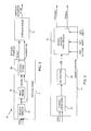
- Fig. 2 is a schematic block diagram 70 illustrating an overall process followed by processor 24 in operating system 10, according to an embodiment of the present invention.
- the processor receives raw unfiltered signals, as voltage levels, from electrodes 20 and 21 and operates on them to form bipolar signal data.
- the processor analyzes the bipolar data to determine a time period, or window, defining a bipolar complex. For simplicity and clarity, in the following description except where otherwise stated there is assumed to be one bipolar complex per heart beat.
- the bipolar complex is bounded by an initial time instance T ONSET and a final time instance T TERMINATION .
- the processor uses the time bounds of the bipolar complex to define a window within which to perform unipolar analysis.
- a unipolar stage 74 the processor considers each of the electrode 20 and 21 signals separately, as unipolar voltage vs. time signals, and analyzes the unipolar signals within the time window found in the bipolar stage. The analysis enables the processor to determine respective unipolar activation times at which the regions in contact with electrodes 20 and 21 activate.
- the activation times typically comprise times at which the derivative of the unipolar signal has a maximum negative value.
- Bipolar stage 72 is formed of three modules: a search window module 76, and two subsequent modules, a first phase module 78 and a second phase module 80. The operations performed by the processor for each module are described below. In the description the signals from electrodes 20 and 21 are assumed to be sampled over a period of approximately 2.5s at a rate of approximately 1 kHz, giving approximately 2,500 samples to be analyzed by system 10. However, system 10 may operate with any convenient sample period and rate of sampling.
- Fig. 3 is a schematic block diagram illustrating search window module 76 in more detail, according to an embodiment of the present invention.
- processor 24 analyzes the set of incoming sample values to identify times at which the R-waves in the sample occurs. Typically for a set of samples taken over 2.5s there are approximately two to four R-waves, although subjects having tachycardia may have five or more R-waves within a 2.5s time period. The identification is typically performed by finding the times at which the sample peaks.
- an RR interval block 92 the processor finds the mean time period RR between the peaks identified in block 92.
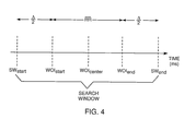
- a search window parameters block 94 the processor calculates times of a start and end times SW START , SW END , of a search window to be used in further analysis of the input data.
- professional 22 is able to program a window of interest (WOI) center time and width, WOI CENTER , WOI WIDTH .
- block 94 uses values of parameters WOI CENTER , WOI WIDTH , together with an additional time period WOI DELTA, also referred to herein using the symbol ⁇ , provided by professional 22.
- WOI CENTER is typically arbitrarily set by the professional to approximate an expected half-way point in time of mean time period RR , but WOI CENTER may be set to be any other convenient point in time.
- WOI WIDTH is typically also arbitrarily set by the professional to approximate an expected mean time period RR but may also be set to any convenient time period.
- block 94 calculates values of SW START , SW END for the search window.
- Fig. 4 is a time line illustrating a relationship between the parameters used in search window parameters block 94, according to an embodiment of the present invention. As is illustrated by the time line, the search window delineated by block 94 has a total width of ( RR + ⁇ ), beginning at a time SW START and ending at a time SW END .
- a typical value for ⁇ is approximately 20 ms.
- a typical value of RR depends on subject 16.
- Fig. 5A is a schematic block diagram illustrating a first set of actions performed by processor 24 in first phase block 78
- Figs. 5B and 5C are schematic voltage vs. time graphs of data before and after the actions, according to embodiments of the present invention. (For simplicity, voltage and time axes for the graphs are not shown.)
- a rectify and filter block 120 bipolar raw data, from electrodes 20 and 21 and illustrated in Fig. 5B , is first rectified, then low-pass filtered to remove high frequency components from the data and to produce smoothed data.
- the inventors use a second order Butterworth filter having a cut off frequency of approximately 20 Hz.
- the filtered smoothed data is then windowed, using the search window times SW START and SW END from block 94 ( Fig. 3 ), to generate a set of sample data ⁇ X(n) ⁇ where n is an index of the data, and X is the data value.
- the set of smoothed data is schematically illustrated in Fig. 5C . Assuming the example search window width given above for a tachycardiac subject, and a sample rate of approximately 1000 Hz, there are approximately 220 smoothed samples in the windowed data, so that in this case n is a positive integer between 1 and approximately 220.
- a threshold voltage level THR that is to be applied in analyzing the data.
- Level THR is selected to be close to, but above, the level of the smoothed baseline data.
- the level is selected as a base value corresponding to the 5 th percentile of the frequency distribution, added with a factor of 5% of the amplitude of the smoothed signal.
- level THR may be selected by any other suitable method for defining a level close to, but above, the smoothed baseline data.
- sort block 122 determines a peak sample X(n p1 ) of the smoothed data.
- the processor supplies level THR, and the sampled smoothed values X(n) to a two-state state machine 124.
- Conditions for transitions between the two states A and B of the state machine are indicated in Fig. 5A within square brackets [ ]; actions performed during the transitions are indicated within braces ⁇ ⁇ .
- Starting from the peak sample X(n p1 ), data X(n) are sequentially fed backward in time until a first transition, at an index underTHRstart, occurs.
- the data are fed forward in time, starting from the peak sample X(n p1 ), until a second transition, at an index underTHRend, occurs.
- a parameter cnt counts the number of samples operated on by the state machine.
- a user-set variable CNTMAX indicative of an acceptable number of samples between transitions underTHRstart and underTHRend, is typically set to be approximately 100, but may be set to be any other convenient number.
- Fig. 6 illustrates the windowed smoothed data output by filter block 120 (as also shown schematically in Fig. 5C ), according to an embodiment of the present invention.
- a graph 130 represents the windowed smoothed samples X(n) output by the filter block.
- State machine 124 divides the samples into three sections: two baseline sections 132 and 134 that are below threshold THR, and a bipolar complex section 136. The bipolar complex is bounded by the two transition indices underTHRstart and underTHRend generated by the state machine.
- Fig. 7A is a schematic block diagram illustrating a second set of actions performed by processor 24 in first phase block 78 ( Fig. 2 ), and Fig. 7B is a schematic graph of data produced by the actions, according to embodiments of the present invention.
- a filter block 150 bipolar raw data from electrodes 20 and 21 is low-pass filtered to remove high frequency components and produce smoothed data.
- the inventors use a second order Butterworth filter having a cut off frequency of approximately 35 Hz.
- a differentiation block 152 the smoothed data is differentiated, and is then rectified in a rectify block 154 to produce rectified differentiated data.
- the data from block 154 is windowed in a window block 156, using the search window times SW START and SW END from block 94 ( Fig. 3 ).
- the windowing generates a set of differentiated smooth data ⁇ D(n) ⁇ where D is the data value.
- Fig. 7B is a graphic illustration of the data output of block 154, shown in more detail in Fig. 9 .
- the set of differentiated smooth data transfers to a sort block 158, as well as to a four-state state machine 160 in second phase 80 of the bipolar stage ( Fig. 2 ).
- sort block 158 the indices, underTHRstart and underTHRend, determined by two-state state machine 124 and illustrated in Fig. 6 , are used to divide ⁇ D(n) ⁇ into a differentiated binary complex section and two noise sections.
- Processor 24 sorts the values in both noise sections into a frequency distribution, and from the distribution a differentiated noise level NOISE, that is to be applied in analyzing the differentiated smooth data, is extracted.
- Level NOISE is selected to be close to, but above, the level of both noise sections, and is shown schematically in Fig. 7B . In one embodiment, the level is based on a 95 th percentile of the frequency distribution.
- Sort block 158 also determines a peak value D(n p2 ) and an index n p2 of the differentiated binary complex, and transfers D(n p2 ) to the four-state state machine.
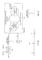
- Fig. 8 is a schematic diagram of four-state state machine 160, according to an embodiment of the present invention.
- the state machine comprises four states A, B, C, and D, together with two exit states E end F. Conditions for transitions between the states are indicated in Fig. 8 within square brackets [ ]; actions performed during the transitions are indicated within braces ⁇ ⁇ .
- sample data D(n) are fed backward in time until exit state F is reached.
- the time, i.e., the index value, at which state F is reached is an onset time, T ONSET , of the bipolar complex.
- a termination time, T TERMINATION of the bipolar complex is found by feeding sample data D(n) forward in time until exit state E is reached.
- parameters cnt and gcnt count the number of samples operated on by the state machine.
- Variables CNTSTATE2, CNTSTATE3, and CNTSTATE4 may be set by professional 22, as representative of acceptable numbers of samples between states of the state machine as transitions occur through the differentiated noise level NOISE.
- Typical values of CNTSTATE2, CNTSTATE3, and CNTSTATE4 are respectively 8, 18, and 4, but the values may be set by professional 22 to any suitable value.
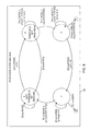
- FIG. 9 illustrates the operation of state machine 160, according to an embodiment of the present invention.
- a graph 170 (similar to Fig. 7B ) represents the smoothed data D(n) transferred from window block 156 to the state machine. Values of noise level NOISE, and PEAK D(n p2 ), transferred from sort block 158, are also shown on graph 170.
- a graph 172 shows the states of the state machine, and the transitions between the states, in determining the value of T ONSET .
- processor 24 ( Fig. 1 ) begins operating the state machine from the peak value D(n p2 ), at sample n p2 , in state A.
- the machine after initially alternating between states A and B, then transfers in turn to states C, D, A, B, and C.
- the machine transfers to exit state F ( Fig. 8 ).
- a similar set of transitions occurs for samples fed forwards-in-time from peak value D(n p2 ) the transitions ending in state D and exit state E and determining the value of T TERMINATION .
- Fig. 10 illustrates values of T ONSET and T TERMINATION plotted on a time line, according to an embodiment of the present invention.
- the time line illustrates a typical relationship between the values of T ONSET and T TERMINATION and the time values used in investigating the bipolar complex and described above with reference to Fig. 4 .
- SNR 20 ⁇ log ⁇ S - N N
- RMS root mean square
- processor 24 transfers the values of T ONSET and T TERMINATION to unipolar stage 74.
- the processor forms a time window, bounded by T ONSET and T TERMINATION , and analyzes the smoothed unipolar voltage (V) vs. time (t) signals from each of electrodes 20 and 21 within the window.
- the processor calculates values of the slopes of each unipolar signal, i.e., values of first derivative dV dt .
- the processor selects the time at which the first derivative dV dt has its most negative, i.e., its minimum, value, and this time is assumed to be the time at which the tissue generating the signal begins to activate.
- FIGs. 11A and 11B are schematic bipolar and unipolar graphs, according to an embodiment of the present invention.
- a graph 180 is a voltage vs. time graph of a bipolar signal
- graphs 182 and 184 are voltage vs. time graphs of respective unipolar signals forming the bipolar signal. Both sets of graphs have times T ONSET and T TERMINATION , as determined above, marked on the graphs.
- respective activation times 186 and 188 being the times of the most negative derivative of the respective unipolar signals within the window defined by T ONSET and T TERMINATION , are shown.
- Activation times 186 and 188 are the times that the tissue generating the unipolar signals begins to activate, and are also herein termed unipolar onset activation times.
- System 10 evaluates signal parameters where there is one bipolar complex per heart beat.
- System 10 is not limited to such evaluations, and may be used to identify signals where multiple bipolar complexes occur per heart beat, and furthermore, to evaluate signal parameters of the multiple bipolar complexes.
- the identification of the occurrence of multiple bipolar signals may typically be by measuring intervals between adjacent complexes, since, in contrast to signals having one bipolar complex per heart beat, the intervals change.
- Figs. 12A, 12B, and 12C are graphs of signals derived from multiple bipolar complexes occurring within one heart beat, according to embodiments of the present invention.
- a graph 190 ( Fig. 12A ) is a bipolar signal exhibiting an atrial bipolar complex 194, and ventricular bipolar complexes 192 and 196.
- Each bipolar complex may be analyzed by initially defining a search window for a given complex.
- a method for defining the search window for each complex is substantially as described above with reference to Fig. 3 , mutatis mutandis , to allow for differing RR intervals within the bipolar signal.
- a graph 200 ( Fig. 12B ) is an enlarged graph of a specific ventricular bipolar complex 192. Onset and termination times 202 and 204 for the complex have been marked on the graph. The times are evaluated substantially as described above with reference to Fig. 8 , by feeding smoothed data derived from the complex through state machine 160.
- a graph 210 ( Fig. 12C ) illustrates unipolar signals 212 and 214 corresponding to bipolar complex 192 of Fig. 12B .
- respective unipolar onset activation times 216 and 218 for each signal occur at the times wherein the first derivative of each signal, measured between onset and termination times 202 and 204, has its most negative value, i.e., is a minimum.
- System 10 may also be used to evaluate other parameters relevant to signals having multiple bipolar complexes occurring within one heart beat, as will be apparent to those of ordinary skill in the art. Such parameters include, but are not limited to, a duration time between first and second atrial bipolar complexes, by measuring a mean RR interval between the complexes. All such parameters are assumed to be included within the scope of the present invention.
- Fig. 13 is a flowchart 250 of steps followed by processor 24 in operating system 10 to determine activation times, according to an embodiment of the present invention.
- the description of the steps of the flowchart assumes that signals received have one bipolar complex per heart beat, except where otherwise stated. Those with ordinary skill in the art will be able to adapt the description for cases having multiple bipolar complexes per heart beat.
- Steps 252 - 260 are actions performed in bipolar stage 72 and step 262 is performed in unipolar stage 74 ( Fig. 2 ).
- the processor receives signals as sampled data from electrodes 20 and 21.
- the processor analyzes the signals to identify R waves, an RR value, and bounds of a search window, as described above with reference to Figs. 3 and 4 .
- a first filtration step 254 the sampled data are rectified, filtered, and windowed, and the resulting smoothed data is fed into two-state state machine 124.
- a demarcation step 256 the two-state state machine divides the data it receives into baseline sections and a bipolar complex section. Steps 254 and 256 are as described above with reference to Figs. 5A-5C and Fig. 6 .
- a second filtration step 258 the sampled data of the bipolar complex are filtered, differentiated and windowed to derive a second smoothed signal, as described above with reference to Figs. 7A and 7B .
- a bipolar complex analysis step 260 the processor evaluates onset and termination times of the complex by feeding the second smoothed signal data into four-state state machine 160, as described with reference to Figs. 8 and 9 .
- an activation time step 262 a time of activation of tissue in contact with electrodes 20 and 21 is determined by analyzing the unipolar signals from each electrode within a window defined by the bipolar onset and termination times of step 260. Actions performed by the processor in step 262 are described with reference to Figs. 11A and 11B , and also (for situations of multiple bipolar complexes in one heart beat) with reference to Figs. 12A-12C .
- the analysis differentiates the unipolar signals within the window, and finds the respective times at which the first derivatives are most negative, i.e., are minima. These times correspond to an onset activation time of the tissue in contact with electrode 20, and an onset activation time of the tissue in contact with electrode 21.
Priority Applications (1)
| Application Number | Priority Date | Filing Date | Title |
|---|---|---|---|
| EP21187233.8A EP3925535A1 (fr) | 2012-04-23 | 2013-04-22 | Détection de temps d'activation cardiaque |
Applications Claiming Priority (1)
| Application Number | Priority Date | Filing Date | Title |
|---|---|---|---|
| US13/453,249 US9833157B2 (en) | 2012-04-23 | 2012-04-23 | Cardiac activation time detection |
Related Child Applications (2)
| Application Number | Title | Priority Date | Filing Date |
|---|---|---|---|
| EP21187233.8A Division EP3925535A1 (fr) | 2012-04-23 | 2013-04-22 | Détection de temps d'activation cardiaque |
| EP21187233.8A Division-Into EP3925535A1 (fr) | 2012-04-23 | 2013-04-22 | Détection de temps d'activation cardiaque |
Publications (2)
| Publication Number | Publication Date |
|---|---|
| EP2656784A1 true EP2656784A1 (fr) | 2013-10-30 |
| EP2656784B1 EP2656784B1 (fr) | 2022-06-22 |
Family
ID=48190721
Family Applications (2)
| Application Number | Title | Priority Date | Filing Date |
|---|---|---|---|
| EP13164723.2A Active EP2656784B1 (fr) | 2012-04-23 | 2013-04-22 | Détection de temps d'activation cardiaque |
| EP21187233.8A Pending EP3925535A1 (fr) | 2012-04-23 | 2013-04-22 | Détection de temps d'activation cardiaque |
Family Applications After (1)
| Application Number | Title | Priority Date | Filing Date |
|---|---|---|---|
| EP21187233.8A Pending EP3925535A1 (fr) | 2012-04-23 | 2013-04-22 | Détection de temps d'activation cardiaque |
Country Status (7)
| Country | Link |
|---|---|
| US (1) | US9833157B2 (fr) |
| EP (2) | EP2656784B1 (fr) |
| JP (1) | JP6309205B2 (fr) |
| CN (1) | CN103549948B (fr) |
| AU (1) | AU2013204274B2 (fr) |
| CA (1) | CA2813586A1 (fr) |
| IL (1) | IL225773B (fr) |
Cited By (4)
| Publication number | Priority date | Publication date | Assignee | Title |
|---|---|---|---|---|
| CN104799850A (zh) * | 2014-01-29 | 2015-07-29 | 韦伯斯特生物官能(以色列)有限公司 | 用于心房纤颤注记的双重双极构型 |
| WO2019209626A1 (fr) * | 2018-04-26 | 2019-10-31 | St. Jude Medical, Cardiology Division, Inc. | Système et procédé pour cartographier des sites d'attaque arythmiques |
| WO2020242940A1 (fr) * | 2019-05-24 | 2020-12-03 | St. Jude Medical, Cardiology Division, Inc. | Système et procédé de cartographie cardiaque |
| EP2901923B1 (fr) * | 2014-01-29 | 2023-02-22 | Biosense Webster (Israel) Ltd. | Détection bipolaire/unipolaire hybride de front d'onde d'activation |
Families Citing this family (9)
| Publication number | Priority date | Publication date | Assignee | Title |
|---|---|---|---|---|
| US10758141B2 (en) * | 2012-04-23 | 2020-09-01 | Biosense Webster (Israel) Ltd. | Cardiac activation time detection |
| JP6273355B2 (ja) | 2013-10-30 | 2018-01-31 | セント・ジュード・メディカル,カーディオロジー・ディヴィジョン,インコーポレイテッド | 電位図の電圧ベースの評価のための心臓マッピングのシステム及び方法 |
| WO2015066113A1 (fr) | 2013-10-30 | 2015-05-07 | St. Jude Medical, Cardiology Division, Inc. | Système de cartographie cardiaque et méthode de détection d'activation bidirectionnelle d'électrocardiogrammes |
| US9833161B2 (en) | 2015-02-09 | 2017-12-05 | Biosense Webster (Israel) Ltd. | Basket catheter with far-field electrode |
| US11058342B2 (en) * | 2016-08-11 | 2021-07-13 | Biosense Webster (Israel) Ltd. | Classifying ECG signals |
| US10383534B2 (en) * | 2016-08-11 | 2019-08-20 | Biosense Webster (Israel) Ltd. | Annotation of a wavefront |
| CN107837083B (zh) * | 2017-10-31 | 2019-05-10 | 太原理工大学 | 基于最小二乘支持向量机的j波自动检测方法 |
| US10932686B2 (en) | 2018-05-22 | 2021-03-02 | Biosense Webster (Israel) Ltd. | Identifying activations in an atrial fibrillation electrogram |
| US11311226B2 (en) | 2019-12-12 | 2022-04-26 | Biosense Webster (Israel) Ltd. | Detection of ventricular activity using unipolar and bipolar signals |
Citations (3)
| Publication number | Priority date | Publication date | Assignee | Title |
|---|---|---|---|---|
| EP1647301A1 (fr) * | 2004-10-12 | 2006-04-19 | Pacesetter, Inc. | Procedé et appareil de stimulation cardiaque à commutation de mode |
| US7225015B1 (en) * | 2003-06-24 | 2007-05-29 | Pacesetter, Inc. | System and method for detecting cardiac ischemia based on T-waves using an implantable medical device |
| EP2591721A1 (fr) * | 2011-11-11 | 2013-05-15 | Biosense Webster (Israel), Ltd. | Annotation de temps précise de signaux ECG intracardiaques |
Family Cites Families (16)
| Publication number | Priority date | Publication date | Assignee | Title |
|---|---|---|---|---|
| JPS6399840A (ja) | 1986-10-17 | 1988-05-02 | テルモ株式会社 | 生体信号計測装置 |
| US5778881A (en) * | 1996-12-04 | 1998-07-14 | Medtronic, Inc. | Method and apparatus for discriminating P and R waves |
| US7218960B1 (en) * | 2003-06-24 | 2007-05-15 | Pacesetter, Inc. | System and method for detecting cardiac ischemia based on T-waves using an implantable medical device |
| US20050059897A1 (en) | 2003-09-17 | 2005-03-17 | Snell Jeffery D. | Statistical analysis for implantable cardiac devices |
| US7194300B2 (en) | 2004-01-21 | 2007-03-20 | Cardionet, Inc. | Cardiac monitoring |
| WO2006066324A1 (fr) | 2004-12-21 | 2006-06-29 | Sydney West Area Health Service | Traitement automatise de donnees electrophysiologiques |
| US7672722B1 (en) | 2005-12-21 | 2010-03-02 | Pacesetter, Inc. | Hardware-based state machine for use in discriminating near field signals from far field signals for use in an implantable cardiac stimulation device |
| US7912535B2 (en) | 2006-03-02 | 2011-03-22 | University Of Rochester | Method and system for assessing repolarization abnormalities |
| JP2008028830A (ja) * | 2006-07-24 | 2008-02-07 | General Res Of Electronics Inc | 位相比較信号処理回路 |
| GB0624081D0 (en) | 2006-12-01 | 2007-01-10 | Oxford Biosignals Ltd | Biomedical signal analysis method |
| US8676303B2 (en) | 2008-05-13 | 2014-03-18 | The Regents Of The University Of California | Methods and systems for treating heart instability |
| CN104873191A (zh) | 2008-10-09 | 2015-09-02 | 加利福尼亚大学董事会 | 用于自动定位生物节律紊乱的源的机器和过程 |
| US8478388B2 (en) | 2009-04-07 | 2013-07-02 | Pacesetter, Inc. | Cardiac coordinate system for motion analysis |
| US9398862B2 (en) | 2009-04-23 | 2016-07-26 | Rhythmia Medical, Inc. | Multi-electrode mapping system |
| EP2453975B1 (fr) * | 2009-07-15 | 2016-11-02 | Cardiac Pacemakers, Inc. | Télédétection dans un dispositif médical implantable |
| US8306614B2 (en) * | 2010-04-28 | 2012-11-06 | Medtronic, Inc. | Method of dual EGM sensing and heart rate estimation in implanted cardiac devices |
-
2012
- 2012-04-23 US US13/453,249 patent/US9833157B2/en active Active
-
2013
- 2013-04-12 AU AU2013204274A patent/AU2013204274B2/en active Active
- 2013-04-15 IL IL225773A patent/IL225773B/en active IP Right Grant
- 2013-04-19 CA CA2813586A patent/CA2813586A1/fr not_active Abandoned
- 2013-04-22 JP JP2013089158A patent/JP6309205B2/ja active Active
- 2013-04-22 EP EP13164723.2A patent/EP2656784B1/fr active Active
- 2013-04-22 EP EP21187233.8A patent/EP3925535A1/fr active Pending
- 2013-04-23 CN CN201310142932.5A patent/CN103549948B/zh active Active
Patent Citations (3)
| Publication number | Priority date | Publication date | Assignee | Title |
|---|---|---|---|---|
| US7225015B1 (en) * | 2003-06-24 | 2007-05-29 | Pacesetter, Inc. | System and method for detecting cardiac ischemia based on T-waves using an implantable medical device |
| EP1647301A1 (fr) * | 2004-10-12 | 2006-04-19 | Pacesetter, Inc. | Procedé et appareil de stimulation cardiaque à commutation de mode |
| EP2591721A1 (fr) * | 2011-11-11 | 2013-05-15 | Biosense Webster (Israel), Ltd. | Annotation de temps précise de signaux ECG intracardiaques |
Cited By (12)
| Publication number | Priority date | Publication date | Assignee | Title |
|---|---|---|---|---|
| CN104799850A (zh) * | 2014-01-29 | 2015-07-29 | 韦伯斯特生物官能(以色列)有限公司 | 用于心房纤颤注记的双重双极构型 |
| EP2901953A1 (fr) * | 2014-01-29 | 2015-08-05 | Biosense Webster (Israel), Ltd. | Double configuration bipolaire pour l'annotation de fibrillation auriculaire |
| US9554718B2 (en) | 2014-01-29 | 2017-01-31 | Biosense Webster (Israel) Ltd. | Double bipolar configuration for atrial fibrillation annotation |
| US10238309B2 (en) | 2014-01-29 | 2019-03-26 | Biosense Webster (Israel) Ltd. | Double bipolar configuration for atrial fibrillation annotation |
| CN104799850B (zh) * | 2014-01-29 | 2019-07-19 | 韦伯斯特生物官能(以色列)有限公司 | 用于心房纤颤注记的双重双极构型 |
| CN110251228A (zh) * | 2014-01-29 | 2019-09-20 | 韦伯斯特生物官能(以色列)有限公司 | 用于心房纤颤注记的双重双极构型 |
| EP3698747A3 (fr) * | 2014-01-29 | 2020-10-28 | Biosense Webster (Israel) Ltd. | Double configuration bipolaire pour l'annotation de fibrillation auriculaire |
| US11229395B2 (en) | 2014-01-29 | 2022-01-25 | Biosense Webster (Israel) Ltd. | Double bipolar configuration for atrial fibrillation annotation |
| CN110251228B (zh) * | 2014-01-29 | 2022-05-31 | 韦伯斯特生物官能(以色列)有限公司 | 用于心房纤颤注记的双重双极构型 |
| EP2901923B1 (fr) * | 2014-01-29 | 2023-02-22 | Biosense Webster (Israel) Ltd. | Détection bipolaire/unipolaire hybride de front d'onde d'activation |
| WO2019209626A1 (fr) * | 2018-04-26 | 2019-10-31 | St. Jude Medical, Cardiology Division, Inc. | Système et procédé pour cartographier des sites d'attaque arythmiques |
| WO2020242940A1 (fr) * | 2019-05-24 | 2020-12-03 | St. Jude Medical, Cardiology Division, Inc. | Système et procédé de cartographie cardiaque |
Also Published As
| Publication number | Publication date |
|---|---|
| IL225773B (en) | 2018-11-29 |
| CN103549948B (zh) | 2018-09-04 |
| EP3925535A1 (fr) | 2021-12-22 |
| AU2013204274A1 (en) | 2013-11-07 |
| JP6309205B2 (ja) | 2018-04-11 |
| CN103549948A (zh) | 2014-02-05 |
| EP2656784B1 (fr) | 2022-06-22 |
| AU2013204274B2 (en) | 2014-10-09 |
| US9833157B2 (en) | 2017-12-05 |
| CA2813586A1 (fr) | 2013-10-23 |
| US20130281870A1 (en) | 2013-10-24 |
| IL225773A0 (en) | 2013-09-30 |
| JP2013223730A (ja) | 2013-10-31 |
Similar Documents
| Publication | Publication Date | Title |
|---|---|---|
| US9833157B2 (en) | Cardiac activation time detection | |
| JP2013223730A5 (fr) | ||
| EP2901923B1 (fr) | Détection bipolaire/unipolaire hybride de front d'onde d'activation | |
| AU2012247057B2 (en) | Accurate time annotation of intracardiac ecg signals | |
| US11890103B2 (en) | Identifying ECG signals having the same morphology | |
| EP3130285A1 (fr) | Comparaison et observation des séquences temporelles d'activation cardiaque | |
| EP2704628A2 (fr) | Moyennage de signaux | |
| CN107847174B (zh) | 起搏信号处理方法、系统和心电监护仪 | |
| CN112914586B (zh) | 心内图案匹配 | |
| EP3352662B1 (fr) | Signaux egm intracardiaques pour correspondance et acceptation de battements | |
| US9642550B2 (en) | Cycle length iteration for the detection of atrial activations from electrogram recordings of atrial fibrillation | |
| US8880352B2 (en) | System and method for analyzing an electrophysiological signal | |
| US10758141B2 (en) | Cardiac activation time detection | |
| CN116831589A (zh) | 一种长时程可穿戴心电信号的最优导联信号选取方法 | |
| CN116807490A (zh) | 心电图的处理方法、装置、医疗设备及存储介质 |
Legal Events
| Date | Code | Title | Description |
|---|---|---|---|
| PUAI | Public reference made under article 153(3) epc to a published international application that has entered the european phase |
Free format text: ORIGINAL CODE: 0009012 |
|
| AK | Designated contracting states |
Kind code of ref document: A1 Designated state(s): AL AT BE BG CH CY CZ DE DK EE ES FI FR GB GR HR HU IE IS IT LI LT LU LV MC MK MT NL NO PL PT RO RS SE SI SK SM TR |
|
| AX | Request for extension of the european patent |
Extension state: BA ME |
|
| 17P | Request for examination filed |
Effective date: 20140430 |
|
| RBV | Designated contracting states (corrected) |
Designated state(s): AL AT BE BG CH CY CZ DE DK EE ES FI FR GB GR HR HU IE IS IT LI LT LU LV MC MK MT NL NO PL PT RO RS SE SI SK SM TR |
|
| STAA | Information on the status of an ep patent application or granted ep patent |
Free format text: STATUS: EXAMINATION IS IN PROGRESS |
|
| 17Q | First examination report despatched |
Effective date: 20170421 |
|
| STAA | Information on the status of an ep patent application or granted ep patent |
Free format text: STATUS: EXAMINATION IS IN PROGRESS |
|
| REG | Reference to a national code |
Ref country code: DE Ref legal event code: R079 Ref document number: 602013081892 Country of ref document: DE Free format text: PREVIOUS MAIN CLASS: A61B0005040000 Ipc: A61B0005283000 |
|
| RIC1 | Information provided on ipc code assigned before grant |
Ipc: A61B 5/283 20210101AFI20210708BHEP Ipc: A61B 5/00 20060101ALI20210708BHEP Ipc: A61B 5/287 20210101ALI20210708BHEP Ipc: A61B 5/316 20210101ALI20210708BHEP Ipc: A61B 5/349 20210101ALI20210708BHEP |
|
| GRAP | Despatch of communication of intention to grant a patent |
Free format text: ORIGINAL CODE: EPIDOSNIGR1 |
|
| STAA | Information on the status of an ep patent application or granted ep patent |
Free format text: STATUS: GRANT OF PATENT IS INTENDED |
|
| GRAJ | Information related to disapproval of communication of intention to grant by the applicant or resumption of examination proceedings by the epo deleted |
Free format text: ORIGINAL CODE: EPIDOSDIGR1 |
|
| GRAP | Despatch of communication of intention to grant a patent |
Free format text: ORIGINAL CODE: EPIDOSNIGR1 |
|
| STAA | Information on the status of an ep patent application or granted ep patent |
Free format text: STATUS: GRANT OF PATENT IS INTENDED |
|
| INTG | Intention to grant announced |
Effective date: 20211013 |
|
| INTG | Intention to grant announced |
Effective date: 20211027 |
|
| GRAJ | Information related to disapproval of communication of intention to grant by the applicant or resumption of examination proceedings by the epo deleted |
Free format text: ORIGINAL CODE: EPIDOSDIGR1 |
|
| STAA | Information on the status of an ep patent application or granted ep patent |
Free format text: STATUS: EXAMINATION IS IN PROGRESS |
|
| INTC | Intention to grant announced (deleted) | ||
| GRAP | Despatch of communication of intention to grant a patent |
Free format text: ORIGINAL CODE: EPIDOSNIGR1 |
|
| STAA | Information on the status of an ep patent application or granted ep patent |
Free format text: STATUS: GRANT OF PATENT IS INTENDED |
|
| GRAS | Grant fee paid |
Free format text: ORIGINAL CODE: EPIDOSNIGR3 |
|
| INTG | Intention to grant announced |
Effective date: 20220422 |
|
| GRAA | (expected) grant |
Free format text: ORIGINAL CODE: 0009210 |
|
| STAA | Information on the status of an ep patent application or granted ep patent |
Free format text: STATUS: THE PATENT HAS BEEN GRANTED |
|
| RAP3 | Party data changed (applicant data changed or rights of an application transferred) |
Owner name: BIOSENSE WEBSTER (ISRAEL) LTD. |
|
| AK | Designated contracting states |
Kind code of ref document: B1 Designated state(s): AL AT BE BG CH CY CZ DE DK EE ES FI FR GB GR HR HU IE IS IT LI LT LU LV MC MK MT NL NO PL PT RO RS SE SI SK SM TR |
|
| REG | Reference to a national code |
Ref country code: GB Ref legal event code: FG4D |
|
| REG | Reference to a national code |
Ref country code: CH Ref legal event code: EP |
|
| REG | Reference to a national code |
Ref country code: DE Ref legal event code: R096 Ref document number: 602013081892 Country of ref document: DE |
|
| REG | Reference to a national code |
Ref country code: AT Ref legal event code: REF Ref document number: 1499256 Country of ref document: AT Kind code of ref document: T Effective date: 20220715 |
|
| REG | Reference to a national code |
Ref country code: IE Ref legal event code: FG4D |
|
| REG | Reference to a national code |
Ref country code: NL Ref legal event code: FP |
|
| REG | Reference to a national code |
Ref country code: LT Ref legal event code: MG9D |
|
| PG25 | Lapsed in a contracting state [announced via postgrant information from national office to epo] |
Ref country code: SE Free format text: LAPSE BECAUSE OF FAILURE TO SUBMIT A TRANSLATION OF THE DESCRIPTION OR TO PAY THE FEE WITHIN THE PRESCRIBED TIME-LIMIT Effective date: 20220622 Ref country code: NO Free format text: LAPSE BECAUSE OF FAILURE TO SUBMIT A TRANSLATION OF THE DESCRIPTION OR TO PAY THE FEE WITHIN THE PRESCRIBED TIME-LIMIT Effective date: 20220922 Ref country code: LT Free format text: LAPSE BECAUSE OF FAILURE TO SUBMIT A TRANSLATION OF THE DESCRIPTION OR TO PAY THE FEE WITHIN THE PRESCRIBED TIME-LIMIT Effective date: 20220622 Ref country code: HR Free format text: LAPSE BECAUSE OF FAILURE TO SUBMIT A TRANSLATION OF THE DESCRIPTION OR TO PAY THE FEE WITHIN THE PRESCRIBED TIME-LIMIT Effective date: 20220622 Ref country code: GR Free format text: LAPSE BECAUSE OF FAILURE TO SUBMIT A TRANSLATION OF THE DESCRIPTION OR TO PAY THE FEE WITHIN THE PRESCRIBED TIME-LIMIT Effective date: 20220923 Ref country code: FI Free format text: LAPSE BECAUSE OF FAILURE TO SUBMIT A TRANSLATION OF THE DESCRIPTION OR TO PAY THE FEE WITHIN THE PRESCRIBED TIME-LIMIT Effective date: 20220622 Ref country code: BG Free format text: LAPSE BECAUSE OF FAILURE TO SUBMIT A TRANSLATION OF THE DESCRIPTION OR TO PAY THE FEE WITHIN THE PRESCRIBED TIME-LIMIT Effective date: 20220922 |
|
| REG | Reference to a national code |
Ref country code: AT Ref legal event code: MK05 Ref document number: 1499256 Country of ref document: AT Kind code of ref document: T Effective date: 20220622 |
|
| PG25 | Lapsed in a contracting state [announced via postgrant information from national office to epo] |
Ref country code: RS Free format text: LAPSE BECAUSE OF FAILURE TO SUBMIT A TRANSLATION OF THE DESCRIPTION OR TO PAY THE FEE WITHIN THE PRESCRIBED TIME-LIMIT Effective date: 20220622 Ref country code: LV Free format text: LAPSE BECAUSE OF FAILURE TO SUBMIT A TRANSLATION OF THE DESCRIPTION OR TO PAY THE FEE WITHIN THE PRESCRIBED TIME-LIMIT Effective date: 20220622 |
|
| PG25 | Lapsed in a contracting state [announced via postgrant information from national office to epo] |
Ref country code: SM Free format text: LAPSE BECAUSE OF FAILURE TO SUBMIT A TRANSLATION OF THE DESCRIPTION OR TO PAY THE FEE WITHIN THE PRESCRIBED TIME-LIMIT Effective date: 20220622 Ref country code: SK Free format text: LAPSE BECAUSE OF FAILURE TO SUBMIT A TRANSLATION OF THE DESCRIPTION OR TO PAY THE FEE WITHIN THE PRESCRIBED TIME-LIMIT Effective date: 20220622 Ref country code: RO Free format text: LAPSE BECAUSE OF FAILURE TO SUBMIT A TRANSLATION OF THE DESCRIPTION OR TO PAY THE FEE WITHIN THE PRESCRIBED TIME-LIMIT Effective date: 20220622 Ref country code: PT Free format text: LAPSE BECAUSE OF FAILURE TO SUBMIT A TRANSLATION OF THE DESCRIPTION OR TO PAY THE FEE WITHIN THE PRESCRIBED TIME-LIMIT Effective date: 20221024 Ref country code: ES Free format text: LAPSE BECAUSE OF FAILURE TO SUBMIT A TRANSLATION OF THE DESCRIPTION OR TO PAY THE FEE WITHIN THE PRESCRIBED TIME-LIMIT Effective date: 20220622 Ref country code: EE Free format text: LAPSE BECAUSE OF FAILURE TO SUBMIT A TRANSLATION OF THE DESCRIPTION OR TO PAY THE FEE WITHIN THE PRESCRIBED TIME-LIMIT Effective date: 20220622 Ref country code: CZ Free format text: LAPSE BECAUSE OF FAILURE TO SUBMIT A TRANSLATION OF THE DESCRIPTION OR TO PAY THE FEE WITHIN THE PRESCRIBED TIME-LIMIT Effective date: 20220622 Ref country code: AT Free format text: LAPSE BECAUSE OF FAILURE TO SUBMIT A TRANSLATION OF THE DESCRIPTION OR TO PAY THE FEE WITHIN THE PRESCRIBED TIME-LIMIT Effective date: 20220622 |
|
| PG25 | Lapsed in a contracting state [announced via postgrant information from national office to epo] |
Ref country code: PL Free format text: LAPSE BECAUSE OF FAILURE TO SUBMIT A TRANSLATION OF THE DESCRIPTION OR TO PAY THE FEE WITHIN THE PRESCRIBED TIME-LIMIT Effective date: 20220622 Ref country code: IS Free format text: LAPSE BECAUSE OF FAILURE TO SUBMIT A TRANSLATION OF THE DESCRIPTION OR TO PAY THE FEE WITHIN THE PRESCRIBED TIME-LIMIT Effective date: 20221022 |
|
| REG | Reference to a national code |
Ref country code: DE Ref legal event code: R097 Ref document number: 602013081892 Country of ref document: DE |
|
| PG25 | Lapsed in a contracting state [announced via postgrant information from national office to epo] |
Ref country code: AL Free format text: LAPSE BECAUSE OF FAILURE TO SUBMIT A TRANSLATION OF THE DESCRIPTION OR TO PAY THE FEE WITHIN THE PRESCRIBED TIME-LIMIT Effective date: 20220622 |
|
| PG25 | Lapsed in a contracting state [announced via postgrant information from national office to epo] |
Ref country code: DK Free format text: LAPSE BECAUSE OF FAILURE TO SUBMIT A TRANSLATION OF THE DESCRIPTION OR TO PAY THE FEE WITHIN THE PRESCRIBED TIME-LIMIT Effective date: 20220622 |
|
| PLBE | No opposition filed within time limit |
Free format text: ORIGINAL CODE: 0009261 |
|
| STAA | Information on the status of an ep patent application or granted ep patent |
Free format text: STATUS: NO OPPOSITION FILED WITHIN TIME LIMIT |
|
| 26N | No opposition filed |
Effective date: 20230323 |
|
| PGFP | Annual fee paid to national office [announced via postgrant information from national office to epo] |
Ref country code: GB Payment date: 20230302 Year of fee payment: 11 |
|
| PGFP | Annual fee paid to national office [announced via postgrant information from national office to epo] |
Ref country code: NL Payment date: 20230314 Year of fee payment: 11 |
|
| PGFP | Annual fee paid to national office [announced via postgrant information from national office to epo] |
Ref country code: DE Payment date: 20230228 Year of fee payment: 11 |
|
| PG25 | Lapsed in a contracting state [announced via postgrant information from national office to epo] |
Ref country code: SI Free format text: LAPSE BECAUSE OF FAILURE TO SUBMIT A TRANSLATION OF THE DESCRIPTION OR TO PAY THE FEE WITHIN THE PRESCRIBED TIME-LIMIT Effective date: 20220622 |
|
| REG | Reference to a national code |
Ref country code: CH Ref legal event code: PL |
|
| PG25 | Lapsed in a contracting state [announced via postgrant information from national office to epo] |
Ref country code: LU Free format text: LAPSE BECAUSE OF NON-PAYMENT OF DUE FEES Effective date: 20230422 |
|
| REG | Reference to a national code |
Ref country code: BE Ref legal event code: MM Effective date: 20230430 |
|
| PG25 | Lapsed in a contracting state [announced via postgrant information from national office to epo] |
Ref country code: MC Free format text: LAPSE BECAUSE OF FAILURE TO SUBMIT A TRANSLATION OF THE DESCRIPTION OR TO PAY THE FEE WITHIN THE PRESCRIBED TIME-LIMIT Effective date: 20220622 |
|
| PG25 | Lapsed in a contracting state [announced via postgrant information from national office to epo] |
Ref country code: MC Free format text: LAPSE BECAUSE OF FAILURE TO SUBMIT A TRANSLATION OF THE DESCRIPTION OR TO PAY THE FEE WITHIN THE PRESCRIBED TIME-LIMIT Effective date: 20220622 Ref country code: LI Free format text: LAPSE BECAUSE OF NON-PAYMENT OF DUE FEES Effective date: 20230430 Ref country code: FR Free format text: LAPSE BECAUSE OF NON-PAYMENT OF DUE FEES Effective date: 20230430 Ref country code: CH Free format text: LAPSE BECAUSE OF NON-PAYMENT OF DUE FEES Effective date: 20230430 |
|
| REG | Reference to a national code |
Ref country code: IE Ref legal event code: MM4A |
|
| PG25 | Lapsed in a contracting state [announced via postgrant information from national office to epo] |
Ref country code: BE Free format text: LAPSE BECAUSE OF NON-PAYMENT OF DUE FEES Effective date: 20230430 |
|
| PG25 | Lapsed in a contracting state [announced via postgrant information from national office to epo] |
Ref country code: IE Free format text: LAPSE BECAUSE OF NON-PAYMENT OF DUE FEES Effective date: 20230422 |