EP2656464B1 - Jointing assembly for electrical cables - Google Patents
Jointing assembly for electrical cables Download PDFInfo
- Publication number
- EP2656464B1 EP2656464B1 EP10805205.1A EP10805205A EP2656464B1 EP 2656464 B1 EP2656464 B1 EP 2656464B1 EP 10805205 A EP10805205 A EP 10805205A EP 2656464 B1 EP2656464 B1 EP 2656464B1
- Authority
- EP
- European Patent Office
- Prior art keywords
- connector
- jointing assembly
- support element
- removable support
- jointing
- Prior art date
- Legal status (The legal status is an assumption and is not a legal conclusion. Google has not performed a legal analysis and makes no representation as to the accuracy of the status listed.)
- Not-in-force
Links
- 239000004020 conductor Substances 0.000 description 11
- 239000003989 dielectric material Substances 0.000 description 9
- 229920002943 EPDM rubber Polymers 0.000 description 5
- 230000000712 assembly Effects 0.000 description 5
- 238000000429 assembly Methods 0.000 description 5
- 229920001971 elastomer Polymers 0.000 description 5
- 239000000463 material Substances 0.000 description 5
- 230000005684 electric field Effects 0.000 description 3
- 239000004033 plastic Substances 0.000 description 3
- 230000008878 coupling Effects 0.000 description 2
- 238000010168 coupling process Methods 0.000 description 2
- 238000005859 coupling reaction Methods 0.000 description 2
- 238000003466 welding Methods 0.000 description 2
- RYGMFSIKBFXOCR-UHFFFAOYSA-N Copper Chemical compound [Cu] RYGMFSIKBFXOCR-UHFFFAOYSA-N 0.000 description 1
- 239000004743 Polypropylene Substances 0.000 description 1
- 239000004411 aluminium Substances 0.000 description 1
- XAGFODPZIPBFFR-UHFFFAOYSA-N aluminium Chemical compound [Al] XAGFODPZIPBFFR-UHFFFAOYSA-N 0.000 description 1
- 229910052782 aluminium Inorganic materials 0.000 description 1
- 230000015556 catabolic process Effects 0.000 description 1
- 238000012412 chemical coupling Methods 0.000 description 1
- 239000010949 copper Substances 0.000 description 1
- 229910052802 copper Inorganic materials 0.000 description 1
- 238000002788 crimping Methods 0.000 description 1
- 239000013536 elastomeric material Substances 0.000 description 1
- 229920001519 homopolymer Polymers 0.000 description 1
- 230000013011 mating Effects 0.000 description 1
- 239000007769 metal material Substances 0.000 description 1
- 238000000465 moulding Methods 0.000 description 1
- 239000000615 nonconductor Substances 0.000 description 1
- -1 polypropylene Polymers 0.000 description 1
- 229920001155 polypropylene Polymers 0.000 description 1
- 230000001681 protective effect Effects 0.000 description 1
Images



Classifications
-
- H—ELECTRICITY
- H01—ELECTRIC ELEMENTS
- H01R—ELECTRICALLY-CONDUCTIVE CONNECTIONS; STRUCTURAL ASSOCIATIONS OF A PLURALITY OF MUTUALLY-INSULATED ELECTRICAL CONNECTING ELEMENTS; COUPLING DEVICES; CURRENT COLLECTORS
- H01R4/00—Electrically-conductive connections between two or more conductive members in direct contact, i.e. touching one another; Means for effecting or maintaining such contact; Electrically-conductive connections having two or more spaced connecting locations for conductors and using contact members penetrating insulation
- H01R4/10—Electrically-conductive connections between two or more conductive members in direct contact, i.e. touching one another; Means for effecting or maintaining such contact; Electrically-conductive connections having two or more spaced connecting locations for conductors and using contact members penetrating insulation effected solely by twisting, wrapping, bending, crimping, or other permanent deformation
-
- H—ELECTRICITY
- H02—GENERATION; CONVERSION OR DISTRIBUTION OF ELECTRIC POWER
- H02G—INSTALLATION OF ELECTRIC CABLES OR LINES, OR OF COMBINED OPTICAL AND ELECTRIC CABLES OR LINES
- H02G15/00—Cable fittings
- H02G15/08—Cable junctions
- H02G15/18—Cable junctions protected by sleeves, e.g. for communication cable
- H02G15/182—Cable junctions protected by sleeves, e.g. for communication cable held in expanded condition in radial direction prior to installation
- H02G15/1826—Cable junctions protected by sleeves, e.g. for communication cable held in expanded condition in radial direction prior to installation on a removable hollow core, e.g. a tube
-
- H—ELECTRICITY
- H01—ELECTRIC ELEMENTS
- H01R—ELECTRICALLY-CONDUCTIVE CONNECTIONS; STRUCTURAL ASSOCIATIONS OF A PLURALITY OF MUTUALLY-INSULATED ELECTRICAL CONNECTING ELEMENTS; COUPLING DEVICES; CURRENT COLLECTORS
- H01R4/00—Electrically-conductive connections between two or more conductive members in direct contact, i.e. touching one another; Means for effecting or maintaining such contact; Electrically-conductive connections having two or more spaced connecting locations for conductors and using contact members penetrating insulation
- H01R4/70—Insulation of connections
- H01R4/72—Insulation of connections using a heat shrinking insulating sleeve
Definitions
- the present invention relates to a jointing assembly for electrical cables, in particular for medium or high voltage electrical cables.
- joining assembly is used to indicate either a joint, that is a jointing assembly specifically provided for mechanically and electrically connecting two electrical cables, or a termination, that is a jointing assembly specifically provided for mechanically and electrically connecting an electrical cable to a different device, such as for example an electrical power source, a transformer, a user device etc.
- the term “medium voltage” is used to refer to a tension typically from about 1 kV to about 30 kV, while the term “high voltage” refers to a tension above 30 kV.
- the term “very high voltage” is used to define a voltage greater than about 150 kV or 220 kV, up to 500 kV or more.
- jointing assemblies for medium or high voltage electrical cables are known.
- a radially shrinkable sleeves is commonly used for enclosing the connected end portions of two electrical cables (in the case of a joint) or the end portion of an electrical cable connected to a different device (in the case of a termination).
- EP 0 435 569 discloses a shrinkable sleeve comprising a dielectric material as an intermediate insulating layer, an electric field control inner layer combined with a partially coated inner conductive layer, and an electrically conducting outer layer.
- a free space (usually called "parking position") on one side of the cable, such a free space having a length corresponding to at least the complete length of the shrinkable sleeve.
- the shrinkable sleeve is centered over the cable connection area and is then shrunk down either by the application of heat or by the removal of an external or internal support element provided for maintaining the shrinkable sleeve in a radially extended state.
- JP 11 0007999 and EP 0 504 035 disclose examples of such jointing assemblies.
- US 5,316,492 discloses a plug-in connection, in particular in a sleeve for high-voltage plastic cables.
- the plug-in connection comprises an electrical insulator fitting closely onto cable ends.
- the cable conductor connecting elements comprise one plug part and one counter-plug part and means for mutually locking the plug part and the counter-plug part.
- WO 2007/130811 shows the preamble of clam 1 and discloses a tubular terminal for a cable comprising a first connector having opposite terminal ends for connecting to respective mating second and third connectors, each one adapted in turn to be connected to a respective cable for making electrical contact therewith.
- the tubular terminal comprises a shrinkable sleeve. A portion of said shrinkable sleeve is fixedly arranged around the connector. The shrinkable sleeve is held in a radially expanded state by two support elements which are adapted to be removed thus causing the shrinkable sleeve to shrink onto the first connector and each of the cable ends connected thereto.
- the Applicant noted that, due to the fact that the first connector of WO 2007/130811 is fixedly associated with the shrinkable sleeve and because of the different elastic properties of the shrinkable sleeve (which has elastic properties) and the first connector, undesired axial movements of the first connector can occur when the shrinkable sleeve is associated to the electrical cables and, more particularly, when the shrinkable sleeve is shrunk onto the first connector and each of the cable ends connected thereto.
- the Applicant faced the technical problem of providing a jointing assembly for electrical cables, in particular for medium or high voltage electrical cables, which is suitable to ensure the desired axial position of a connector provided within a shrinkable sleeve to be maintained when associating the jointing assembly with the electrical cables, particularly when a plug-in connector is used.
- the Applicant found that the above technical problem can be solved by mechanically coupling the connector to at least one of the removable support elements by means of at least one stop element which projects from at least one of the connector and the support element and contacts the other one of the connector and the support element so as to prevent an axial movement of said connector with respect to said at least one removable support element.
- the Applicant observed that, due to the fact that the connector is mechanically coupled to the removable support element, the axial position of the connector is not altered by the elastic behaviour of the shrinkable sleeve when this shrinks onto the connector, so that the desired axial position can be maintained during the jointing operation.
- the present invention relates to a jointing assembly for electrical cables, comprising:
- radial and axial are used to indicate a perpendicular direction and a parallel direction, respectively, to a reference longitudinal axis of the jointing assembly, the above reference longitudinal axis being defined by the longitudinal axis of the connector.
- the expression “radially inner/outer” is instead used by referring to the position along a radial direction with respect to the abovementioned longitudinal axis, while the expression “axially inner/outer” is used by referring to the position along a parallel direction to the aforementioned longitudinal axis and with respect to a reference plane perpendicular to said longitudinal axis and intersecting said connector in a central portion thereof.
- the jointing assembly of the present invention can comprise at least one of the following preferred features.
- said at least one removable support element is defined by a tubular body.
- said tubular body comprises a frusto-conical portion.
- said tubular body comprises two half shells having frusto-conical portions.
- said tubular body further comprises a cylindrical end portion.
- Said connector can be mechanically coupled to said frusto-conical portion or to said cylindrical end portion.
- said at least one stop element is made in a single piece with said at least one removable support element or said connector.
- said at least one stop element is made as a separate piece from said at least one removable support element or said connector.
- Said at least one stop element can be firmly associated with said at least one removable support element or said connector, or can be pivotally mounted on said at least one removable support element or said connector, so as to define a first operative configuration wherein said at least one stop element contacts the other of said at least one removable support element and said connector, and a second operative configuration wherein said at least one stop element does not contact the other of said at least one removable support element and said connector.
- the jointing assembly comprises at least two stop elements.
- said at least two stop elements are symmetrically arranged with respect to said longitudinal axis.
- said connector comprises:
- said two removable support elements are symmetrically arranged with respect to said connector.
- a jointing assembly for electrical cables is indicated with numeral reference 10.
- the jointing assembly of figure 1 is a joint which is shown in an operative configuration wherein it mechanically and electrically connects two medium or high voltage electrical cables 100a, 100b.
- Each electrical cable 100a, 100b comprises at least one conductor 101a, 101b and an insulating layer 102a, 102b coaxially applied at a radially outer position to the at least one conductor 101a, 101b.
- a conductive screen 103a, 103b is coaxially applied at a radially outer position to the insulating layer 102a, 102b.
- the conductive screen 103a, 103b is in turn covered with at least one protective sheath 104a, 104b of electrically insulating plastic or elastomeric material.
- each electrical cable 100a, 100b further comprises at least one semi-conductive sheath 105a, 105b radially interposed between the insulating layer 102a, 102b and the conductive screen 103a, 103b.
- each cable 100a, 100b is treated in such a manner that the conductors 101a, 101b axially project by a predetermined amount with respect to the respective outer layers, as clearly shown in figure 1 .
- the jointing assembly 10 comprises a connector 11, suitable for plug-in mounting, extending about a longitudinal axis X-X.
- the connector 11 is a socket connector, which comprises axially opposite end portions 11a, 11b each provided with a seat 12a, 12b adapted to house and lock into a desired axial position a respective plug (not shown) associated with a respective electrical cable 100a, 100b.
- the plug comprises a seat adapted to receive and hold the end portion of the electrical cable 100, 100b by means of clamping, crimping, screws or welding.
- the connector 11 is made of a metallic material, preferably tinned aluminium. It comprises two opposite axially outer surfaces 110a, 110b and a radial tubular surface 111 having a cylindrical central portion and two axially opposite conical portions.
- the jointing assembly 10 comprises, in a radially outer position with respect to the connector 11, a radially shrinkable sleeve 20.
- the sleeve 20 can be made from heat or cold shrinkable dielectric materials. These dielectric materials are generally known by the man skilled in the art.
- the sleeve 20 is made of a cold shrinkable dielectric material, such as rubber EPDM.
- the sleeve 20 extends coaxially to the longitudinal axis X-X and has a length greater than that of the connector 11.
- the connector 11 is centrally arranged within the sleeve 20 along the longitudinal axis X-X so as to have a symmetrical arrangement of the sleeve 20 about the connector 11 along the longitudinal axis X-X.
- the sleeve 20 comprises, at a radially inner portion thereof, a first cylindrical insert 21 made of a conductive or semi-conductive material. Throughout the following description, the insert 21 will be indicated as "electrode”.
- the electrode 21 is made of a semi-conductive material. More preferably, such a material is rubber EPDM.
- the electrode 21 extends coaxially to the longitudinal axis X-X and has a length greater than that of the connector 11 and lower than that of the sleeve 20.
- the electrode 21 is symmetrically arranged with respect the connector 11 and the sleeve 20 along the longitudinal axis X-X.
- the sleeve 20 further comprises, at each of the end portions 20a, 20b thereof, a respective second cylindrical insert 22a, 22b, made of a conductive or semi-conductive material.
- a respective second cylindrical insert 22a, 22b made of a conductive or semi-conductive material.
- the deflectors 22a, 22b cooperate with the electrode 21 to control the electrical field within jointing assembly 10, in particular to avoid the presence of areas with high concentration of electrical field, wherein undesired electrical discharges and breakdowns could occur.
- the deflectors 22a, 22b are made of semi-conductive material. More preferably such a material is rubber EPDM. Alternatively, the deflectors 22a, 22b are made from a material with high permittivity.
- Each of the deflectors 22a, 22b extends coaxially to the longitudinal axis X-X and axially projects inside the sleeve 20 toward the electrode 21 so that the radially inner portion of the sleeve 20 is defined, moving from the central portion toward each of the end portions 20a, 20b thereof, by the electrode 21, the dielectric material of the sleeve 20 and the deflector 22a, 22b.
- the electrode 21 and the deflectors 22a, 22b are thus incorporated into the dielectric material of the sleeve 20.
- the electrode and the deflectors are not incorporated into the dielectric material of the sleeve 20, but are arranged in a radially inner position with respect to the radially inner surface of the sleeve 20.
- the sleeve 20, together with the electrode 21 and the deflectors 22a, 22b, is held in a radially expanded state by two support elements 30a, 30b which are radially interposed between the connector 11 and the sleeve 20 and symmetrically arranged along the longitudinal axis X-X with respect to the connector 11.
- the support elements 30a, 30b are associated with each other by a connecting element (not shown) which held the support elements 30a, 30b within the sleeve 20.
- Each support element 30a, 30b has a length greater than half of the length of the connector 11 so that when the support elements 30a, 30b are properly arranged within the sleeve 20 and are in contact with each other, the sum of the lengths of the two support elements 30a, 30b is greater than that of the sleeve 20.
- the support elements 30a, 30b are axially removed from the opposite end portions 20a, 20b of the sleeve 20 along opposite directions (see arrows A1 e A2 in figure 2 ), thus causing the sleeve 20, together with the electrode 21 and the deflectors 22a, 22b, to shrink onto the connector 11 and each of the cable end portions connected thereto.
- the aforementioned connecting element is broken.
- each support element 30a, 30b comprises a rigid tubular body 31a, 31b made of a plastic material.
- each of the tubular body 21a, 31b is made of a charged homopolymer polypropylene.
- Each tubular body 31a, 31b comprises an axially outer frusto-conical portion 32a, 32b and an axially inner cylindrical end portion 33a, 33b.
- the tubular body 31a, 31b are thus arranged within the sleeve 20 so that the two axially inner cylindrical end portions 33a, 33b face to one another.
- Each tubular body 31a, 31b is preferably formed by two half shells which are associated to each other when the tubular body 31a, 31b is arranged within the sleeve 20 and move away from one another when the tubular body 31a, 31b is out of the sleeve 20.
- each support element is defined by a helically wound strip which is adapted to be removed from the respective end portion of the sleeve by pulling a free end portion of the strip.
- the jointing assembly 10 of figures 1 and 2 further comprises, in a radially outer position with respect to the sleeve 20, a first shield 40.
- the shield 40 has a length substantially equal to that of the sleeve 20.
- the shield 40 is made of a two-layer sheath including a radially inner layer and a radially outer layer.
- the radially inner layer is preferably made of a dielectric material, more preferably rubber EPDM.
- the radially outer layer is preferably made of a semi-conductive material, more preferably rubber EPDM.
- a metallic screen 50 is provided in a radially outer position with respect to the first shield 40.
- the screen 50 has a length greater than that of the sleeve 20 and is preferably made of tinned copper.
- the jointing assembly 10 further comprises, in a radially outer position with respect to the screen 50, a second shield 60 having preferably a length substantially greater than that of the screen 50.
- the shield 60 is made of a two-layer sheath, that is it includes a radially inner layer made from a dielectric material and a radially outer layer made from a semi-conductive material. More preferably, the same material of the shield 40 is used.
- the connector 11 is mechanically coupled to each support element 30a, 30b by at least two pairs of stop elements 70a, 70b which are symmetrically arranged on axially opposite sides with respect to the connector 11.
- At least two stop elements 70a are arranged equidistant from one another at a predetermined axial distance from the free end of the tubular element 31a.
- Each of the stop elements 70a projects from the radially inner surface of the support element 30a along a direction substantially perpendicular to the longitudinal axis X-X.
- the top elements 70a radially project from the frusto-conical portion 32a of the support element 30a toward the longitudinal axis X-X.
- the stop elements 70a are in abutment against the axially outer surface 110a of the connector 11 so as to prevent any movement of the connector 11 along the axially outer free end portion of the support element 30a. Since, the stop elements 70b are similarly in abutment against the opposite axially outer surface 110b of the connector 11 so as to prevent any movement of the connector 11 along the opposite axially outer free end portion of the support element 30b, it follows that the stop elements 70a and 70b prevent any axial movement of the connector 11 along both way of a direction parallel to the longitudinal axis X-X.
- Each of the stop elements 70a can be made in a single piece with the support element 30a by moulding, as shown in the detail of figure 8a .
- each of the stop elements 70a can be made as a separate piece from the support element 30a, as shown in the detail of figure 8b .
- the stop element can be firmly associated with the support element 30a by cold or hot welding or alternatively by mechanical or chemical coupling.
- each of the stop elements 70a can be pivotally mounted on the support element 30a so as to define a first operative configuration wherein the stop elements 70a are in a first position ( figure 8c ) such that they contact the connector 11 thus preventing any axial movement thereof, and a second operative configuration wherein the stop elements 70a are in a second position ( figure 8d ) such that they do not contact the connector 11 thus making the support element 30a free to move axially with respect to the connector 11.
- Each stop element 70a has preferably a circular transversal section and a rounded free end portion.
- each pair of stop elements 70a, 70b is replaced by a single stop element projecting from the radially inner surface of the support element 30a and circumferentially extending about the longitudinal axis X-X.
- FIG 4 A different embodiment of the jointing assembly 10 of the present invention is shown in figure 4 .
- structural elements which are identical or functionally equivalent to those described above with respect to figures 1-3 are indicated with the same numeral references and will not be further described.
- the embodiment of figure 4 differs from the embodiment of figures 2 and 3 in that the stop elements 70a are shorter than those of the embodiment of figures 2 and 3 and in that they abut against the conical portion of the radially outer surface 111 of the connector 11. Similar considerations apply to the stop elements 70b.
- FIG. 5 A portion of a further different embodiment of the jointing assembly 10 of the present invention is shown in figure 5 .
- structural elements which are identical, or functionally equivalent, to those described above with respect to figures 1-4 are indicated with the same numeral references and will not be further described.
- the embodiment of figure 5 differs from the embodiment of figures 2 and 3 in that the stop elements 70a, 70b are housed into respective seats 112a, 112b which are circumferentially formed in the conical portion of the radially outer surface 111 of the connector 11 and in that the stop elements 70a, 70b project from the cylindrical end portions 33a, 33b of the support elements 30a, 30b.
- FIG. 6 A portion of a further different embodiment of the jointing assembly 10 of the present invention is shown in figure 6 .
- structural elements which are identical, or functionally equivalent, to those described above with respect to figures 1-5 are indicated with the same numeral references and will not be further described.
- the embodiment of figure 6 differs from the embodiment of figure 5 in that the support elements 30a, 30b, being not identical to each other, are not symmetrically arranged with respect to the connector 1.
- the support element 30a comprises an axially outer frusto-conical portion 32a and an axially inner cylindrical end portions 33a, while the support element 30b comprises just a frusto-conical portion 32b.
- the stop elements 70 are arranged on the cylindrical end portion 33a of the support element 30a while the stop elements 70b are arranged on the axially inner end portion of the frusto-conical portion 32b of the support element 30b.
- FIG. 7 A portion of a further different embodiment of the jointing assembly 10 of the present invention is shown in figure 7 .
- structural elements which are identical, or functionally equivalent, to those described above with respect to figures 1-6 are indicated with the same numeral references and will not be further described.
- the embodiment of figure 7 differs from the embodiment of figure 6 in that the stop elements 70a are arranged on the frusto-conical portion 32a and in that the stop elements 70a, 70b abut against the axially outer surfaces 110a, 110b of the connector 11, as in the embodiment of figures 2 and 3 .
- FIG. 9a A portion of a further different embodiment of the jointing assembly 10 of the present invention is shown in figures 9a and 9b .
- structural elements which are identical, or functionally equivalent, to those described above with respect to figures 1-8 are indicated with the same numeral references and will not be further described.
- FIG. 9a and 8b differs from the embodiment of figures 2 and 3 in that the stop elements 70a, 70b are pivotally mounted - in the same way as shown in figures 8c and 8d - on the radially outer surface 111 of the connector 11 and are adapted to be housed into circumferential seats 300a, 300b formed in the radially inner surface of the support elements 30a, 30b, respectively.
- the stop elements 70a, 70b are in a first operative position wherein they radially project from the radially outer surface 111 of the connector 11 (in particular from the cylindrical central portion thereof) and axially abut against respective abutment surfaces 301a, 301b formed in the seats 300a, 300b, respectively, thus defining a first operative configuration wherein the connector 11 is prevented to axially move with respect to the support elements 30a, 30b.
- the connector 11 is mechanically coupled to the support elements 30a, 30b up to when the support elements 30a, 30b are moved out from the jointing assembly 10 to cause the sleeve 20 to shrink onto the connector 11 and the end portion of the electrical cables attached thereto. Therefore, when the sleeve 20 starts to shrink no undesired stress is exerted on the connector 11 as at that time there is no contact between sleeve 20 and connector 11 yet. Thus, the desired axial position of the connector 11 within the jointing assembly 10 is not altered by the shrinking action of the sleeve 20 at the beginning of the shrinking. Upon contacting the connector 11 during shrinking, the sleeve 20 exerts on the connector 11 a radial force which locks into position the connector 11, so that the desired axial position of the connector 11 is not altered up to the end of the shrinking action.
- the provision of the stop elements 70a, 70b makes easier the positioning of the connector 11 at the desired axial position within the jointing assembly 10 when assembling the jointing assembly 10. Indeed, once the stop elements 70a, 70b are arranged on one of the connector 11 and support elements 30a, 30b at the desired axial position from the free end thereof, the connector 11 can be axially inserted into the support element 30a, 30b and moved up to when the stop elements 70a, 70b contact the abutment surface on the other element between connector 11 and tubular elements 30a, 300b.
Landscapes
- Cable Accessories (AREA)
- Details Of Connecting Devices For Male And Female Coupling (AREA)
- Connector Housings Or Holding Contact Members (AREA)
Description
- The present invention relates to a jointing assembly for electrical cables, in particular for medium or high voltage electrical cables.
- Throughout the present description and the attached claims, the term "jointing assembly" is used to indicate either a joint, that is a jointing assembly specifically provided for mechanically and electrically connecting two electrical cables, or a termination, that is a jointing assembly specifically provided for mechanically and electrically connecting an electrical cable to a different device, such as for example an electrical power source, a transformer, a user device etc.
- In the present description, the term "medium voltage" is used to refer to a tension typically from about 1 kV to about 30 kV, while the term "high voltage" refers to a tension above 30 kV. The term "very high voltage" is used to define a voltage greater than about 150 kV or 220 kV, up to 500 kV or more.
- Different kinds of jointing assemblies for medium or high voltage electrical cables are known. In these jointing assemblies a radially shrinkable sleeves is commonly used for enclosing the connected end portions of two electrical cables (in the case of a joint) or the end portion of an electrical cable connected to a different device (in the case of a termination).
-
EP 0 435 569 discloses a shrinkable sleeve comprising a dielectric material as an intermediate insulating layer, an electric field control inner layer combined with a partially coated inner conductive layer, and an electrically conducting outer layer. - When making cable splices or cable end terminations by means of a known radially shrinkable sleeve, it is generally provided a free space (usually called "parking position") on one side of the cable, such a free space having a length corresponding to at least the complete length of the shrinkable sleeve.
- After the cable connection is established, the shrinkable sleeve is centered over the cable connection area and is then shrunk down either by the application of heat or by the removal of an external or internal support element provided for maintaining the shrinkable sleeve in a radially extended state.
- Other known jointing assemblies provide for the use of plug-in connectors.
JP 11 0007999 EP 0 504 035 disclose examples of such jointing assemblies.US 5,316,492 discloses a plug-in connection, in particular in a sleeve for high-voltage plastic cables. The plug-in connection comprises an electrical insulator fitting closely onto cable ends. The cable conductor connecting elements comprise one plug part and one counter-plug part and means for mutually locking the plug part and the counter-plug part. -
WO 2007/130811 shows the preamble of clam 1 and discloses a tubular terminal for a cable comprising a first connector having opposite terminal ends for connecting to respective mating second and third connectors, each one adapted in turn to be connected to a respective cable for making electrical contact therewith. The tubular terminal comprises a shrinkable sleeve. A portion of said shrinkable sleeve is fixedly arranged around the connector. The shrinkable sleeve is held in a radially expanded state by two support elements which are adapted to be removed thus causing the shrinkable sleeve to shrink onto the first connector and each of the cable ends connected thereto. - The Applicant observed that known jointing assemblies have many drawbacks. In particular the Applicant observed that, in order to achieve a proper electrical and mechanical connection between the connector provided within the shrinkable sleeve and the cable ends, great attention must be paid, in the design stage of the shrinkable sleeve and when associating the shrinkable sleeve with the electrical cables, to the axial position of the first connector within the shrinkable sleeve. In particular, the desired axial position of the first connector, which is determined at the design stage of the shrinkable sleeve, must be maintained when associating the shrinkable sleeve with the electrical cables and up to the end of the junction operation.
- For example, the Applicant noted that, due to the fact that the first connector of
WO 2007/130811 is fixedly associated with the shrinkable sleeve and because of the different elastic properties of the shrinkable sleeve (which has elastic properties) and the first connector, undesired axial movements of the first connector can occur when the shrinkable sleeve is associated to the electrical cables and, more particularly, when the shrinkable sleeve is shrunk onto the first connector and each of the cable ends connected thereto. - The Applicant faced the technical problem of providing a jointing assembly for electrical cables, in particular for medium or high voltage electrical cables, which is suitable to ensure the desired axial position of a connector provided within a shrinkable sleeve to be maintained when associating the jointing assembly with the electrical cables, particularly when a plug-in connector is used.
- The Applicant found that this problem can be solved by mechanically coupling a connector provided within a shrinkable sleeve to the removable support elements provided to hold the shrinkable sleeve in the radially expanded state.
- In particular, the Applicant found that the above technical problem can be solved by mechanically coupling the connector to at least one of the removable support elements by means of at least one stop element which projects from at least one of the connector and the support element and contacts the other one of the connector and the support element so as to prevent an axial movement of said connector with respect to said at least one removable support element.
- The Applicant observed that, due to the fact that the connector is mechanically coupled to the removable support element, the axial position of the connector is not altered by the elastic behaviour of the shrinkable sleeve when this shrinks onto the connector, so that the desired axial position can be maintained during the jointing operation.
- Accordingly, the present invention relates to a jointing assembly for electrical cables, comprising:
- a connector extending about a longitudinal axis and provided, at at least one end portion thereof, with at least one housing seat for at least one free end of a respective electrical cable;
- a shrinkable sleeve coaxially arranged in a radially outer position with respect to said connector;
wherein said shrinkable sleeve is held in a radially expanded state by at least one removable support element radially interposed between said connector and said shrinkable sleeve;
wherein said connector is mechanically coupled to said at least one removable support element by at least one stop element which radially projects from at least one of said connector and said at least one removable support element and contacts the other one of said connector and said at least one removable support element. - An axial movement of said connector with respect to said at least one removable support element is thus prevented.
- Throughout the present description and in the following claims, the terms "radial" and "axial" (or "longitudinal") are used to indicate a perpendicular direction and a parallel direction, respectively, to a reference longitudinal axis of the jointing assembly, the above reference longitudinal axis being defined by the longitudinal axis of the connector. The expression "radially inner/outer" is instead used by referring to the position along a radial direction with respect to the abovementioned longitudinal axis, while the expression "axially inner/outer" is used by referring to the position along a parallel direction to the aforementioned longitudinal axis and with respect to a reference plane perpendicular to said longitudinal axis and intersecting said connector in a central portion thereof.
- The jointing assembly of the present invention can comprise at least one of the following preferred features.
- Preferably, said at least one removable support element is defined by a tubular body.
- More preferably, said tubular body comprises a frusto-conical portion.
- Still more preferably, said tubular body comprises two half shells having frusto-conical portions.
- In an embodiment of the jointing assembly, said tubular body further comprises a cylindrical end portion.
- Said connector can be mechanically coupled to said frusto-conical portion or to said cylindrical end portion.
- In an embodiment, said at least one stop element is made in a single piece with said at least one removable support element or said connector.
- In an alternative embodiment of the jointing assembly, said at least one stop element is made as a separate piece from said at least one removable support element or said connector.
- Said at least one stop element can be firmly associated with said at least one removable support element or said connector, or can be pivotally mounted on said at least one removable support element or said connector, so as to define a first operative configuration wherein said at least one stop element contacts the other of said at least one removable support element and said connector, and a second operative configuration wherein said at least one stop element does not contact the other of said at least one removable support element and said connector.
- In a preferred embodiment thereof, the jointing assembly comprises at least two stop elements.
- Preferably, said at least two stop elements are symmetrically arranged with respect to said longitudinal axis.
- In a preferred embodiment of the jointing assembly, said connector comprises:
- two axially opposite end portions, each of said two end portions being provided with a respective housing seat for a respective free end of a respective electrical cable, and
- two axially opposite removable support elements, each of said two removable support elements being radially interposed between a respective one of said end portions and said shrinkable sleeve.
- Preferably, said two removable support elements are symmetrically arranged with respect to said connector.
- Further features and advantages of the jointing assembly will appear more clearly from the following detailed description of some preferred embodiments thereof, such description being provided merely by way of non-limiting example and being made with reference to the annexed drawings. In such drawings:
-
figure 1 is a schematic, partially sectioned, view of a jointing assembly according to the present invention in an operative configuration wherein it mechanically and electrically connects two electrical cables; -
figure 2 is a schematic sectional view of a first embodiment of a jointing assembly according to the present invention; -
figure 3 is a schematic enlarged sectional view of a portion of the jointing assembly offigure 2 ; -
figure 4 is a schematic sectional view of a second embodiment of a jointing assembly according to the present invention; -
figure 5 is a schematic sectional view of a portion of a different embodiment of a jointing assembly according to the present invention; -
figure 6 is a schematic sectional view of a portion of a further different embodiment of a jointing assembly according to the present invention; -
figure 7 is a schematic sectional view of a portion of a further different embodiment of a jointing assembly according to the present invention; -
figures 8a-8d are enlarged views of different embodiments of a detail of a jointing assembly according to the present invention; -
figure 9a is a schematic sectional view of a further different embodiment of a jointing assembly according to the present invention in a first operative configuration; -
figure 9b is a schematic sectional view of the jointing assembly offigure 9a in a second operative configuration. - With respect to
figure 1 , a jointing assembly for electrical cables according to the present invention is indicated withnumeral reference 10. In particular, the jointing assembly offigure 1 is a joint which is shown in an operative configuration wherein it mechanically and electrically connects two medium or high voltageelectrical cables 100a, 100b. - Each
electrical cable 100a, 100b comprises at least one conductor 101a, 101b and an insulating layer 102a, 102b coaxially applied at a radially outer position to the at least one conductor 101a, 101b. Aconductive screen 103a, 103b is coaxially applied at a radially outer position to the insulating layer 102a, 102b. Theconductive screen 103a, 103b is in turn covered with at least one protective sheath 104a, 104b of electrically insulating plastic or elastomeric material. - As shown in
figure 1 , preferably eachelectrical cable 100a, 100b further comprises at least one semi-conductive sheath 105a, 105b radially interposed between the insulating layer 102a, 102b and theconductive screen 103a, 103b. - In order to expose the conductors 101a, 101b, the end portion of each
cable 100a, 100b is treated in such a manner that the conductors 101a, 101b axially project by a predetermined amount with respect to the respective outer layers, as clearly shown infigure 1 . - As better shown in
figure 2 , thejointing assembly 10 comprises aconnector 11, suitable for plug-in mounting, extending about a longitudinal axis X-X. - The
connector 11 is a socket connector, which comprises axiallyopposite end portions 11a, 11b each provided with a seat 12a, 12b adapted to house and lock into a desired axial position a respective plug (not shown) associated with a respectiveelectrical cable 100a, 100b. - The plug comprises a seat adapted to receive and hold the end portion of the
electrical cable - After each of the plugs associated with the end portions of the
electrical cables connector 11 in a conventional manner (for example, as disclosed inUS 5,316,492 ), thus providing an electrical connection between the twoelectrical cables 100a, 100b. - The
connector 11 is made of a metallic material, preferably tinned aluminium. It comprises two opposite axially outer surfaces 110a, 110b and a radialtubular surface 111 having a cylindrical central portion and two axially opposite conical portions. - The
jointing assembly 10 comprises, in a radially outer position with respect to theconnector 11, a radiallyshrinkable sleeve 20. Thesleeve 20 can be made from heat or cold shrinkable dielectric materials. These dielectric materials are generally known by the man skilled in the art. Preferably, thesleeve 20 is made of a cold shrinkable dielectric material, such as rubber EPDM. - The
sleeve 20 extends coaxially to the longitudinal axis X-X and has a length greater than that of theconnector 11. Theconnector 11 is centrally arranged within thesleeve 20 along the longitudinal axis X-X so as to have a symmetrical arrangement of thesleeve 20 about theconnector 11 along the longitudinal axis X-X. - The
sleeve 20 comprises, at a radially inner portion thereof, a firstcylindrical insert 21 made of a conductive or semi-conductive material. Throughout the following description, theinsert 21 will be indicated as "electrode". - Preferably, the
electrode 21 is made of a semi-conductive material. More preferably, such a material is rubber EPDM. - The
electrode 21 extends coaxially to the longitudinal axis X-X and has a length greater than that of theconnector 11 and lower than that of thesleeve 20. Theelectrode 21 is symmetrically arranged with respect theconnector 11 and thesleeve 20 along the longitudinal axis X-X. - The
sleeve 20 further comprises, at each of the end portions 20a, 20b thereof, a respective secondcylindrical insert 22a, 22b, made of a conductive or semi-conductive material. Throughout the following description, theinserts 22a, 22b will be indicated as "deflectors". - The
deflectors 22a, 22b cooperate with theelectrode 21 to control the electrical field withinjointing assembly 10, in particular to avoid the presence of areas with high concentration of electrical field, wherein undesired electrical discharges and breakdowns could occur. - Preferably, the
deflectors 22a, 22b are made of semi-conductive material. More preferably such a material is rubber EPDM. Alternatively, thedeflectors 22a, 22b are made from a material with high permittivity. - Each of the
deflectors 22a, 22b extends coaxially to the longitudinal axis X-X and axially projects inside thesleeve 20 toward theelectrode 21 so that the radially inner portion of thesleeve 20 is defined, moving from the central portion toward each of the end portions 20a, 20b thereof, by theelectrode 21, the dielectric material of thesleeve 20 and thedeflector 22a, 22b. - In the jointing assembly of
figure 1 theelectrode 21 and thedeflectors 22a, 22b are thus incorporated into the dielectric material of thesleeve 20. - In an alternative embodiment (not shown), the electrode and the deflectors are not incorporated into the dielectric material of the
sleeve 20, but are arranged in a radially inner position with respect to the radially inner surface of thesleeve 20. - As shown in
figure 2 , thesleeve 20, together with theelectrode 21 and thedeflectors 22a, 22b, is held in a radially expanded state by twosupport elements connector 11 and thesleeve 20 and symmetrically arranged along the longitudinal axis X-X with respect to theconnector 11. In this configuration, thesupport elements support elements sleeve 20. - Each
support element connector 11 so that when thesupport elements sleeve 20 and are in contact with each other, the sum of the lengths of the twosupport elements sleeve 20. - After having mechanically and electrically coupled the two electrical cables to the
connector 11, thesupport elements sleeve 20 along opposite directions (see arrows A1 e A2 infigure 2 ), thus causing thesleeve 20, together with theelectrode 21 and thedeflectors 22a, 22b, to shrink onto theconnector 11 and each of the cable end portions connected thereto. In order to remove thesupport elements - As better shown in
figure 3 , eachsupport element tubular body 31a, 31b made of a plastic material. Preferably, each of the tubular body 21a, 31b is made of a charged homopolymer polypropylene. - Each
tubular body 31a, 31b comprises an axially outer frusto-conical portion cylindrical end portion tubular body 31a, 31b are thus arranged within thesleeve 20 so that the two axially innercylindrical end portions - Each
tubular body 31a, 31b is preferably formed by two half shells which are associated to each other when thetubular body 31a, 31b is arranged within thesleeve 20 and move away from one another when thetubular body 31a, 31b is out of thesleeve 20. - In an alternative embodiment (not shown) of the jointing assembly of the present invention, each support element is defined by a helically wound strip which is adapted to be removed from the respective end portion of the sleeve by pulling a free end portion of the strip.
- The
jointing assembly 10 offigures 1 and2 further comprises, in a radially outer position with respect to thesleeve 20, afirst shield 40. Theshield 40 has a length substantially equal to that of thesleeve 20. - Preferably, the
shield 40 is made of a two-layer sheath including a radially inner layer and a radially outer layer. - The radially inner layer is preferably made of a dielectric material, more preferably rubber EPDM. The radially outer layer is preferably made of a semi-conductive material, more preferably rubber EPDM.
- In a radially outer position with respect to the
first shield 40, ametallic screen 50 is provided. Thescreen 50 has a length greater than that of thesleeve 20 and is preferably made of tinned copper. - The
jointing assembly 10 further comprises, in a radially outer position with respect to thescreen 50, asecond shield 60 having preferably a length substantially greater than that of thescreen 50. - Preferably, the
shield 60 is made of a two-layer sheath, that is it includes a radially inner layer made from a dielectric material and a radially outer layer made from a semi-conductive material. More preferably, the same material of theshield 40 is used. - As shown in
figures 2 and3 , theconnector 11 is mechanically coupled to eachsupport element stop elements 70a, 70b which are symmetrically arranged on axially opposite sides with respect to theconnector 11. - In the following of the present description reference will be made to only one of the aforementioned support elements (in particular, the
support element 30a) and to the respective stop elements (in particular, thestop elements 70a). However, the following description will identically apply to the other one of the aforementioned support elements (the support element 31b) and the respective stop elements (the stop elements 70b), unless when expressly stated the contrary. - At least two
stop elements 70a are arranged equidistant from one another at a predetermined axial distance from the free end of thetubular element 31a. - Each of the
stop elements 70a projects from the radially inner surface of thesupport element 30a along a direction substantially perpendicular to the longitudinal axis X-X. In particular, thetop elements 70a radially project from the frusto-conical portion 32a of thesupport element 30a toward the longitudinal axis X-X. - The
stop elements 70a are in abutment against the axially outer surface 110a of theconnector 11 so as to prevent any movement of theconnector 11 along the axially outer free end portion of thesupport element 30a. Since, the stop elements 70b are similarly in abutment against the opposite axially outer surface 110b of theconnector 11 so as to prevent any movement of theconnector 11 along the opposite axially outer free end portion of thesupport element 30b, it follows that thestop elements 70a and 70b prevent any axial movement of theconnector 11 along both way of a direction parallel to the longitudinal axis X-X. - Each of the
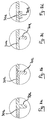
stop elements 70a can be made in a single piece with thesupport element 30a by moulding, as shown in the detail offigure 8a . - Alternatively, each of the
stop elements 70a can be made as a separate piece from thesupport element 30a, as shown in the detail offigure 8b . In this case, the stop element can be firmly associated with thesupport element 30a by cold or hot welding or alternatively by mechanical or chemical coupling. - Alternatively, each of the
stop elements 70a can be pivotally mounted on thesupport element 30a so as to define a first operative configuration wherein thestop elements 70a are in a first position (figure 8c ) such that they contact theconnector 11 thus preventing any axial movement thereof, and a second operative configuration wherein thestop elements 70a are in a second position (figure 8d ) such that they do not contact theconnector 11 thus making thesupport element 30a free to move axially with respect to theconnector 11. - Each
stop element 70a has preferably a circular transversal section and a rounded free end portion. - In an alternative embodiment not shown, each pair of
stop elements 70a, 70b is replaced by a single stop element projecting from the radially inner surface of thesupport element 30a and circumferentially extending about the longitudinal axis X-X. - A different embodiment of the
jointing assembly 10 of the present invention is shown infigure 4 . In this figure, structural elements which are identical or functionally equivalent to those described above with respect tofigures 1-3 are indicated with the same numeral references and will not be further described. - The embodiment of
figure 4 differs from the embodiment offigures 2 and3 in that thestop elements 70a are shorter than those of the embodiment offigures 2 and3 and in that they abut against the conical portion of the radiallyouter surface 111 of theconnector 11. Similar considerations apply to the stop elements 70b. - A portion of a further different embodiment of the
jointing assembly 10 of the present invention is shown infigure 5 . In this figure, structural elements which are identical, or functionally equivalent, to those described above with respect tofigures 1-4 are indicated with the same numeral references and will not be further described. - The embodiment of
figure 5 differs from the embodiment offigures 2 and3 in that thestop elements 70a, 70b are housed into respective seats 112a, 112b which are circumferentially formed in the conical portion of the radiallyouter surface 111 of theconnector 11 and in that thestop elements 70a, 70b project from thecylindrical end portions support elements - A portion of a further different embodiment of the
jointing assembly 10 of the present invention is shown infigure 6 . In this figure, structural elements which are identical, or functionally equivalent, to those described above with respect tofigures 1-5 are indicated with the same numeral references and will not be further described. - The embodiment of
figure 6 differs from the embodiment offigure 5 in that thesupport elements - In particular, the
support element 30a comprises an axially outer frusto-conical portion 32a and an axially innercylindrical end portions 33a, while thesupport element 30b comprises just a frusto-conical portion 32b. Thestop elements 70 are arranged on thecylindrical end portion 33a of thesupport element 30a while the stop elements 70b are arranged on the axially inner end portion of the frusto-conical portion 32b of thesupport element 30b. - A portion of a further different embodiment of the
jointing assembly 10 of the present invention is shown infigure 7 . In this figure, structural elements which are identical, or functionally equivalent, to those described above with respect tofigures 1-6 are indicated with the same numeral references and will not be further described. - The embodiment of
figure 7 differs from the embodiment offigure 6 in that thestop elements 70a are arranged on the frusto-conical portion 32a and in that thestop elements 70a, 70b abut against the axially outer surfaces 110a, 110b of theconnector 11, as in the embodiment offigures 2 and3 . - A portion of a further different embodiment of the
jointing assembly 10 of the present invention is shown infigures 9a and 9b . In these figures, structural elements which are identical, or functionally equivalent, to those described above with respect tofigures 1-8 are indicated with the same numeral references and will not be further described. - The embodiment of
figures 9a and8b differs from the embodiment offigures 2 and3 in that thestop elements 70a, 70b are pivotally mounted - in the same way as shown infigures 8c and 8d - on the radiallyouter surface 111 of theconnector 11 and are adapted to be housed into circumferential seats 300a, 300b formed in the radially inner surface of thesupport elements - In particular, as shown in
figure 9a , when thesupport elements support elements sleeve 20 to hold the sleeve in the radially expanded state), thestop elements 70a, 70b are in a first operative position wherein they radially project from the radiallyouter surface 111 of the connector 11 (in particular from the cylindrical central portion thereof) and axially abut against respective abutment surfaces 301a, 301b formed in the seats 300a, 300b, respectively, thus defining a first operative configuration wherein theconnector 11 is prevented to axially move with respect to thesupport elements - Differently, as shown in
figure 9b , when thesupport elements stop elements 70a, 70b are in a second operative position wherein they lay on the radiallyouter surface 111 of theconnector 11 and are out of the seats 300a, 300b, thus defining a second operative configuration wherein thesupport elements connector 11. - Advantageously, in all the above described embodiments the
connector 11 is mechanically coupled to thesupport elements support elements jointing assembly 10 to cause thesleeve 20 to shrink onto theconnector 11 and the end portion of the electrical cables attached thereto. Therefore, when thesleeve 20 starts to shrink no undesired stress is exerted on theconnector 11 as at that time there is no contact betweensleeve 20 andconnector 11 yet. Thus, the desired axial position of theconnector 11 within thejointing assembly 10 is not altered by the shrinking action of thesleeve 20 at the beginning of the shrinking. Upon contacting theconnector 11 during shrinking, thesleeve 20 exerts on theconnector 11 a radial force which locks into position theconnector 11, so that the desired axial position of theconnector 11 is not altered up to the end of the shrinking action. - In addition thereof, the provision of the
stop elements 70a, 70b makes easier the positioning of theconnector 11 at the desired axial position within thejointing assembly 10 when assembling thejointing assembly 10. Indeed, once thestop elements 70a, 70b are arranged on one of theconnector 11 andsupport elements connector 11 can be axially inserted into thesupport element stop elements 70a, 70b contact the abutment surface on the other element betweenconnector 11 andtubular elements 30a, 300b. - The skilled person will understand that, starting from the above described different embodiments of the jointing assembly of the present invention, a plurality of further different embodiments can be foreseen by combining in different ways the various features described above. All these embodiments are indeed encompassed by the present invention and are within the scope of protection defined by the attached claims.
- While the above description has been made referring to a jointing assembly for connecting two electrical cables, that is a joint, the description also applies in the case of a jointing assembly for connecting an electrical cable to a different device (such as for example an electrical power source, a transformer, a user device), that is a termination, in those cases where such a termination comprises features analogous to those herewith described and/or claimed. Therefore, both a joint and a termination are encompassed by the present invention and are within the scope of protection defined by the attached claims.
Claims (14)
- Jointing assembly (10) for electrical cables, comprising:- a connector (11) extending about a longitudinal axis (X-X) and provided, at at least one end portion (11a, 11b) thereof, with at least one housing seat (12a, 12b) for at least one free end of a respective electrical cable (100a, 100b);- a shrinkable sleeve (20) coaxially arranged in a radially outer position with respect to said connector (11); wherein said shrinkable sleeve (20) is held in a radially expanded state by at least one removable support element (30a, 30b) radially interposed between said connector (11) and said shrinkable sleeve (20);characterised in that said connector (11) is mechanically coupled to said at least one removable support element (30a, 30b) by at least one stop element (70a, 70b) which radially projects from at least one of said connector (11) and said at least one removable support element (30a, 30b) and contacts the other one of said connector (11) and said at least one removable support element (30a, 30b).
- Jointing assembly (10) according to claim 1, wherein said at least one removable support element (30a, 30b) is defined by a tubular body (31a, 31b).
- Jointing assembly (10) according to claim 2, wherein said tubular body (31a, 31b) comprises a frusto-conical portion (32a, 32b).
- Jointing assembly (10) according to claim 3, wherein said tubular body (31a, 31b) further comprises a cylindrical end portion (33a, 33b).
- Jointing assembly (10) according to claim 3 or 4, wherein said connector (11) is mechanically coupled to said frusto-conical portion (32a, 32b).
- Jointing assembly (10) according to claim 4, wherein said connector (11) is mechanically coupled to said cylindrical end portion (33a, 33b).
- Jointing assembly (10) according to any of the previous claims, wherein said at least one stop element (70a, 70b) is made in a single piece with said at least one removable support element (30a, 30b) or said connector (11).
- Jointing assembly (10) according to according to any of claims 1 to 6, wherein said at least one stop element (70a, 70b) is made as a separate piece from said at least one removable support element (30a, 30b) or said connector (11).
- Jointing assembly (10) according to claim 8, wherein said at least one stop element (70a, 70b) is firmly associated with said at least one removable support element (30a, 30b) or said connector (11).
- Jointing assembly (10) according to claim 8, wherein said at least one stop element (70a, 70b) is pivotally mounted on said at least one removable support element (30a, 30b) or said connector (11) so as to define a first operative configuration wherein said at least one stop element (70a, 70b) contacts the other of said at least one removable support element (30a, 30b) and said connector (11) and a second operative configuration wherein said at least one stop element (70a, 70b) does not contact the other of said at least one removable support element (30a, 30b) and said connector (11).
- Jointing assembly (10) according to any of the previous claims, comprising at least two stop elements (70a, 70b).
- Jointing assembly (10) according to claim 11, wherein said at least two stop elements (70a, 70b) are symmetrically arranged with respect to said longitudinal axis (X-X).
- Jointing assembly (10) according to any of the previous claims, wherein said connector (11) comprises:- two axially opposite end portions (11a, 11b), each of said two end portions (11a, 11b) being provided with a respective housing seat (12a, 12b) for a respective free end of a respective electrical cable (100a, 100b), and- two axially opposite removable support elements (30a, 30b), each of said two removable support elements (30a, 30b) being radially interposed between a respective one of said end portions (11a, 11b) and said shrinkable sleeve (20).
- Jointing assembly (10) according to claim 13, wherein said two removable support elements (30a, 30b) are symmetrically arranged with respect to said connector (11).
Applications Claiming Priority (1)
| Application Number | Priority Date | Filing Date | Title |
|---|---|---|---|
| PCT/EP2010/007851 WO2012083984A1 (en) | 2010-12-22 | 2010-12-22 | Jointing assembly for electrical cables |
Publications (2)
| Publication Number | Publication Date |
|---|---|
| EP2656464A1 EP2656464A1 (en) | 2013-10-30 |
| EP2656464B1 true EP2656464B1 (en) | 2016-03-30 |
Family
ID=44534948
Family Applications (1)
| Application Number | Title | Priority Date | Filing Date |
|---|---|---|---|
| EP10805205.1A Not-in-force EP2656464B1 (en) | 2010-12-22 | 2010-12-22 | Jointing assembly for electrical cables |
Country Status (10)
| Country | Link |
|---|---|
| US (1) | US9219318B2 (en) |
| EP (1) | EP2656464B1 (en) |
| CN (1) | CN103283101A (en) |
| AR (1) | AR084418A1 (en) |
| AU (1) | AU2010366145B2 (en) |
| BR (1) | BR112013015789A2 (en) |
| CA (1) | CA2819920A1 (en) |
| NZ (1) | NZ611638A (en) |
| RU (1) | RU2557796C2 (en) |
| WO (1) | WO2012083984A1 (en) |
Families Citing this family (6)
| Publication number | Priority date | Publication date | Assignee | Title |
|---|---|---|---|---|
| US8853563B2 (en) | 2010-04-16 | 2014-10-07 | Thomas & Betts International, Llc | Cold shrink assembly |
| US9202612B2 (en) | 2012-09-28 | 2015-12-01 | Thomas & Betts International, Llc | Cold shrink assembly |
| CN104466874B (en) * | 2013-09-22 | 2018-06-26 | 泰科电子(上海)有限公司 | Cable Wire-to-wire connector, cable Wire-to-wire connector component and the CA cable assembly for being provided with Wire-to-wire connector |
| CN106505509A (en) * | 2016-11-11 | 2017-03-15 | 杭州电缆股份有限公司 | A kind of 500kV cable systems transition joint mounting process |
| EP3647796B1 (en) * | 2018-10-30 | 2023-06-07 | Prysmian S.p.A. | Shrinkable cable joint and voltage sensor |
| JP7017591B2 (en) * | 2020-02-04 | 2022-02-08 | 矢崎総業株式会社 | Wire with terminal and sensor fixing method |
Family Cites Families (13)
| Publication number | Priority date | Publication date | Assignee | Title |
|---|---|---|---|---|
| JPS5939691A (en) | 1982-08-31 | 1984-03-05 | 松下電工株式会社 | Lifting gear |
| US5365020A (en) * | 1989-04-20 | 1994-11-15 | Pirelli Cavi S.P.A. | Cable joint coverings, devices for applying such coverings and joints obtained therewith |
| NL8901138A (en) | 1989-05-03 | 1990-12-03 | Nkf Kabel Bv | PLUG-IN CONNECTION FOR HIGH-VOLTAGE PLASTIC CABLES. |
| DE3943296C2 (en) | 1989-12-29 | 1994-08-11 | Minnesota Mining & Mfg | Sleeve for covering a connection or an end of an electrical cable |
| FR2674073B1 (en) * | 1991-03-12 | 1996-05-10 | Pirelli Cables | CONNECTION DEVICE FOR ONE OR TWO ELECTRIC CABLES, AND PROCEDURE FOR MOUNTING THIS DEVICE AT THE END OF THE CABLE (S) |
| EP0767523A3 (en) * | 1995-10-02 | 1997-07-23 | Minnesota Mining & Mfg | Improved covering device |
| JP4082757B2 (en) * | 1997-06-11 | 2008-04-30 | スリーエム カンパニー | Covered tube of wire connection part and wire connection device |
| FR2825529B1 (en) | 2001-05-29 | 2003-07-25 | Sagem | EXPANSION HOLDING DEVICE OF AN ELASTIC SLEEVE |
| RU2258287C2 (en) * | 2003-07-24 | 2005-08-10 | Андреев Евгений Миратович | Apparatus for joining cable conductors |
| ES2379356T3 (en) * | 2004-10-27 | 2012-04-25 | Prysmian S.P.A. | Procedure and device for coating the connection area between at least two elongated elements, in particular between electric cables |
| KR101366943B1 (en) | 2006-05-05 | 2014-02-24 | 쓰리엠 이노베이티브 프로퍼티즈 컴파니 | Tubular terminal for a cable |
| ATE450914T1 (en) * | 2006-05-05 | 2009-12-15 | 3M Innovative Properties Co | TUBULAR CABLE CONNECTION |
| US7863521B2 (en) * | 2006-12-11 | 2011-01-04 | 3M Innovative Properties Company | Cold shrink article and method of using cold shrink article |
-
2010
- 2010-12-22 CA CA2819920A patent/CA2819920A1/en not_active Abandoned
- 2010-12-22 BR BR112013015789A patent/BR112013015789A2/en not_active IP Right Cessation
- 2010-12-22 US US13/992,904 patent/US9219318B2/en not_active Expired - Fee Related
- 2010-12-22 WO PCT/EP2010/007851 patent/WO2012083984A1/en not_active Ceased
- 2010-12-22 NZ NZ611638A patent/NZ611638A/en not_active IP Right Cessation
- 2010-12-22 RU RU2013133920/07A patent/RU2557796C2/en not_active IP Right Cessation
- 2010-12-22 CN CN201080070827XA patent/CN103283101A/en active Pending
- 2010-12-22 EP EP10805205.1A patent/EP2656464B1/en not_active Not-in-force
- 2010-12-22 AU AU2010366145A patent/AU2010366145B2/en not_active Expired - Fee Related
-
2011
- 2011-12-20 AR ARP110104793A patent/AR084418A1/en unknown
Also Published As
| Publication number | Publication date |
|---|---|
| US9219318B2 (en) | 2015-12-22 |
| NZ611638A (en) | 2015-01-30 |
| AU2010366145A1 (en) | 2013-07-04 |
| US20130341087A1 (en) | 2013-12-26 |
| EP2656464A1 (en) | 2013-10-30 |
| RU2013133920A (en) | 2015-01-27 |
| AU2010366145B2 (en) | 2016-05-05 |
| WO2012083984A1 (en) | 2012-06-28 |
| RU2557796C2 (en) | 2015-07-27 |
| AR084418A1 (en) | 2013-05-15 |
| CA2819920A1 (en) | 2012-06-28 |
| CN103283101A (en) | 2013-09-04 |
| BR112013015789A2 (en) | 2018-05-29 |
Similar Documents
| Publication | Publication Date | Title |
|---|---|---|
| EP1092252B1 (en) | Pre-assembled electrical splice component | |
| JP6788096B2 (en) | Ferrule assembly for electrical connectors | |
| AU2010366145B2 (en) | Jointing assembly for electrical cables | |
| BR102015010710A2 (en) | method of splice of a plurality of shielded wire cables, and wire harness assembly | |
| EP2168212A2 (en) | An adapter, a cable connector with the adapter and a cable connector assembly | |
| JP7033212B2 (en) | High voltage cable joint structure | |
| CA2819928C (en) | Process for manufacturing a jointing assembly for medium or high voltage electrical cables and jointing assembly obtainable by said process | |
| RU2325743C2 (en) | Electric connecting device | |
| EP1852949B1 (en) | Tubular terminal for a cable | |
| JP6628245B2 (en) | Terminal section of aluminum conductor cable | |
| CA2819926C (en) | Screen connector for electrical cables and jointing assembly comprising said screen connector | |
| JP7479341B2 (en) | Cable end structure and method for forming same | |
| CN117060325B (en) | Power cable | |
| JPH09308040A (en) | High-voltage cable end treatment method | |
| JPH08191519A (en) | Insulation block for cable connection and method for forming insulation | |
| JPH07193961A (en) | Cable end |
Legal Events
| Date | Code | Title | Description |
|---|---|---|---|
| PUAI | Public reference made under article 153(3) epc to a published international application that has entered the european phase |
Free format text: ORIGINAL CODE: 0009012 |
|
| 17P | Request for examination filed |
Effective date: 20130715 |
|
| AK | Designated contracting states |
Kind code of ref document: A1 Designated state(s): AL AT BE BG CH CY CZ DE DK EE ES FI FR GB GR HR HU IE IS IT LI LT LU LV MC MK MT NL NO PL PT RO RS SE SI SK SM TR |
|
| DAX | Request for extension of the european patent (deleted) | ||
| REG | Reference to a national code |
Ref country code: DE Ref legal event code: R079 Ref document number: 602010031871 Country of ref document: DE Free format text: PREVIOUS MAIN CLASS: H02G0015180000 Ipc: H01R0004720000 |
|
| RIC1 | Information provided on ipc code assigned before grant |
Ipc: H01R 4/10 20060101ALI20150903BHEP Ipc: H01R 4/72 20060101AFI20150903BHEP Ipc: H02G 15/18 20060101ALI20150903BHEP |
|
| GRAP | Despatch of communication of intention to grant a patent |
Free format text: ORIGINAL CODE: EPIDOSNIGR1 |
|
| INTG | Intention to grant announced |
Effective date: 20151016 |
|
| GRAS | Grant fee paid |
Free format text: ORIGINAL CODE: EPIDOSNIGR3 |
|
| GRAA | (expected) grant |
Free format text: ORIGINAL CODE: 0009210 |
|
| AK | Designated contracting states |
Kind code of ref document: B1 Designated state(s): AL AT BE BG CH CY CZ DE DK EE ES FI FR GB GR HR HU IE IS IT LI LT LU LV MC MK MT NL NO PL PT RO RS SE SI SK SM TR |
|
| REG | Reference to a national code |
Ref country code: GB Ref legal event code: FG4D |
|
| REG | Reference to a national code |
Ref country code: CH Ref legal event code: EP |
|
| REG | Reference to a national code |
Ref country code: AT Ref legal event code: REF Ref document number: 786283 Country of ref document: AT Kind code of ref document: T Effective date: 20160415 |
|
| REG | Reference to a national code |
Ref country code: IE Ref legal event code: FG4D |
|
| REG | Reference to a national code |
Ref country code: DE Ref legal event code: R096 Ref document number: 602010031871 Country of ref document: DE |
|
| REG | Reference to a national code |
Ref country code: LT Ref legal event code: MG4D |
|
| PG25 | Lapsed in a contracting state [announced via postgrant information from national office to epo] |
Ref country code: GR Free format text: LAPSE BECAUSE OF FAILURE TO SUBMIT A TRANSLATION OF THE DESCRIPTION OR TO PAY THE FEE WITHIN THE PRESCRIBED TIME-LIMIT Effective date: 20160701 Ref country code: FI Free format text: LAPSE BECAUSE OF FAILURE TO SUBMIT A TRANSLATION OF THE DESCRIPTION OR TO PAY THE FEE WITHIN THE PRESCRIBED TIME-LIMIT Effective date: 20160330 Ref country code: NO Free format text: LAPSE BECAUSE OF FAILURE TO SUBMIT A TRANSLATION OF THE DESCRIPTION OR TO PAY THE FEE WITHIN THE PRESCRIBED TIME-LIMIT Effective date: 20160630 Ref country code: HR Free format text: LAPSE BECAUSE OF FAILURE TO SUBMIT A TRANSLATION OF THE DESCRIPTION OR TO PAY THE FEE WITHIN THE PRESCRIBED TIME-LIMIT Effective date: 20160330 |
|
| REG | Reference to a national code |
Ref country code: NL Ref legal event code: MP Effective date: 20160330 |
|
| REG | Reference to a national code |
Ref country code: AT Ref legal event code: MK05 Ref document number: 786283 Country of ref document: AT Kind code of ref document: T Effective date: 20160330 |
|
| PG25 | Lapsed in a contracting state [announced via postgrant information from national office to epo] |
Ref country code: LV Free format text: LAPSE BECAUSE OF FAILURE TO SUBMIT A TRANSLATION OF THE DESCRIPTION OR TO PAY THE FEE WITHIN THE PRESCRIBED TIME-LIMIT Effective date: 20160330 Ref country code: LT Free format text: LAPSE BECAUSE OF FAILURE TO SUBMIT A TRANSLATION OF THE DESCRIPTION OR TO PAY THE FEE WITHIN THE PRESCRIBED TIME-LIMIT Effective date: 20160330 Ref country code: SE Free format text: LAPSE BECAUSE OF FAILURE TO SUBMIT A TRANSLATION OF THE DESCRIPTION OR TO PAY THE FEE WITHIN THE PRESCRIBED TIME-LIMIT Effective date: 20160330 Ref country code: RS Free format text: LAPSE BECAUSE OF FAILURE TO SUBMIT A TRANSLATION OF THE DESCRIPTION OR TO PAY THE FEE WITHIN THE PRESCRIBED TIME-LIMIT Effective date: 20160330 |
|
| PG25 | Lapsed in a contracting state [announced via postgrant information from national office to epo] |
Ref country code: NL Free format text: LAPSE BECAUSE OF FAILURE TO SUBMIT A TRANSLATION OF THE DESCRIPTION OR TO PAY THE FEE WITHIN THE PRESCRIBED TIME-LIMIT Effective date: 20160330 |
|
| PG25 | Lapsed in a contracting state [announced via postgrant information from national office to epo] |
Ref country code: IS Free format text: LAPSE BECAUSE OF FAILURE TO SUBMIT A TRANSLATION OF THE DESCRIPTION OR TO PAY THE FEE WITHIN THE PRESCRIBED TIME-LIMIT Effective date: 20160730 Ref country code: EE Free format text: LAPSE BECAUSE OF FAILURE TO SUBMIT A TRANSLATION OF THE DESCRIPTION OR TO PAY THE FEE WITHIN THE PRESCRIBED TIME-LIMIT Effective date: 20160330 Ref country code: PL Free format text: LAPSE BECAUSE OF FAILURE TO SUBMIT A TRANSLATION OF THE DESCRIPTION OR TO PAY THE FEE WITHIN THE PRESCRIBED TIME-LIMIT Effective date: 20160330 |
|
| PG25 | Lapsed in a contracting state [announced via postgrant information from national office to epo] |
Ref country code: PT Free format text: LAPSE BECAUSE OF FAILURE TO SUBMIT A TRANSLATION OF THE DESCRIPTION OR TO PAY THE FEE WITHIN THE PRESCRIBED TIME-LIMIT Effective date: 20160801 Ref country code: RO Free format text: LAPSE BECAUSE OF FAILURE TO SUBMIT A TRANSLATION OF THE DESCRIPTION OR TO PAY THE FEE WITHIN THE PRESCRIBED TIME-LIMIT Effective date: 20160330 Ref country code: SK Free format text: LAPSE BECAUSE OF FAILURE TO SUBMIT A TRANSLATION OF THE DESCRIPTION OR TO PAY THE FEE WITHIN THE PRESCRIBED TIME-LIMIT Effective date: 20160330 Ref country code: SM Free format text: LAPSE BECAUSE OF FAILURE TO SUBMIT A TRANSLATION OF THE DESCRIPTION OR TO PAY THE FEE WITHIN THE PRESCRIBED TIME-LIMIT Effective date: 20160330 Ref country code: ES Free format text: LAPSE BECAUSE OF FAILURE TO SUBMIT A TRANSLATION OF THE DESCRIPTION OR TO PAY THE FEE WITHIN THE PRESCRIBED TIME-LIMIT Effective date: 20160330 Ref country code: CZ Free format text: LAPSE BECAUSE OF FAILURE TO SUBMIT A TRANSLATION OF THE DESCRIPTION OR TO PAY THE FEE WITHIN THE PRESCRIBED TIME-LIMIT Effective date: 20160330 Ref country code: AT Free format text: LAPSE BECAUSE OF FAILURE TO SUBMIT A TRANSLATION OF THE DESCRIPTION OR TO PAY THE FEE WITHIN THE PRESCRIBED TIME-LIMIT Effective date: 20160330 |
|
| PG25 | Lapsed in a contracting state [announced via postgrant information from national office to epo] |
Ref country code: IT Free format text: LAPSE BECAUSE OF FAILURE TO SUBMIT A TRANSLATION OF THE DESCRIPTION OR TO PAY THE FEE WITHIN THE PRESCRIBED TIME-LIMIT Effective date: 20160330 Ref country code: BE Free format text: LAPSE BECAUSE OF FAILURE TO SUBMIT A TRANSLATION OF THE DESCRIPTION OR TO PAY THE FEE WITHIN THE PRESCRIBED TIME-LIMIT Effective date: 20160330 |
|
| REG | Reference to a national code |
Ref country code: DE Ref legal event code: R097 Ref document number: 602010031871 Country of ref document: DE |
|
| PG25 | Lapsed in a contracting state [announced via postgrant information from national office to epo] |
Ref country code: DK Free format text: LAPSE BECAUSE OF FAILURE TO SUBMIT A TRANSLATION OF THE DESCRIPTION OR TO PAY THE FEE WITHIN THE PRESCRIBED TIME-LIMIT Effective date: 20160330 |
|
| PLBE | No opposition filed within time limit |
Free format text: ORIGINAL CODE: 0009261 |
|
| STAA | Information on the status of an ep patent application or granted ep patent |
Free format text: STATUS: NO OPPOSITION FILED WITHIN TIME LIMIT |
|
| 26N | No opposition filed |
Effective date: 20170103 |
|
| PG25 | Lapsed in a contracting state [announced via postgrant information from national office to epo] |
Ref country code: SI Free format text: LAPSE BECAUSE OF FAILURE TO SUBMIT A TRANSLATION OF THE DESCRIPTION OR TO PAY THE FEE WITHIN THE PRESCRIBED TIME-LIMIT Effective date: 20160330 |
|
| REG | Reference to a national code |
Ref country code: DE Ref legal event code: R119 Ref document number: 602010031871 Country of ref document: DE |
|
| REG | Reference to a national code |
Ref country code: CH Ref legal event code: PL |
|
| GBPC | Gb: european patent ceased through non-payment of renewal fee |
Effective date: 20161222 |
|
| PG25 | Lapsed in a contracting state [announced via postgrant information from national office to epo] |
Ref country code: MC Free format text: LAPSE BECAUSE OF FAILURE TO SUBMIT A TRANSLATION OF THE DESCRIPTION OR TO PAY THE FEE WITHIN THE PRESCRIBED TIME-LIMIT Effective date: 20160330 |
|
| REG | Reference to a national code |
Ref country code: FR Ref legal event code: ST Effective date: 20170831 |
|
| REG | Reference to a national code |
Ref country code: IE Ref legal event code: MM4A |
|
| PG25 | Lapsed in a contracting state [announced via postgrant information from national office to epo] |
Ref country code: FR Free format text: LAPSE BECAUSE OF NON-PAYMENT OF DUE FEES Effective date: 20170102 Ref country code: LI Free format text: LAPSE BECAUSE OF NON-PAYMENT OF DUE FEES Effective date: 20161231 Ref country code: CH Free format text: LAPSE BECAUSE OF NON-PAYMENT OF DUE FEES Effective date: 20161231 Ref country code: LU Free format text: LAPSE BECAUSE OF NON-PAYMENT OF DUE FEES Effective date: 20161222 |
|
| PG25 | Lapsed in a contracting state [announced via postgrant information from national office to epo] |
Ref country code: IE Free format text: LAPSE BECAUSE OF NON-PAYMENT OF DUE FEES Effective date: 20161222 Ref country code: DE Free format text: LAPSE BECAUSE OF NON-PAYMENT OF DUE FEES Effective date: 20170701 Ref country code: GB Free format text: LAPSE BECAUSE OF NON-PAYMENT OF DUE FEES Effective date: 20161222 |
|
| PG25 | Lapsed in a contracting state [announced via postgrant information from national office to epo] |
Ref country code: CY Free format text: LAPSE BECAUSE OF FAILURE TO SUBMIT A TRANSLATION OF THE DESCRIPTION OR TO PAY THE FEE WITHIN THE PRESCRIBED TIME-LIMIT Effective date: 20160330 Ref country code: HU Free format text: LAPSE BECAUSE OF FAILURE TO SUBMIT A TRANSLATION OF THE DESCRIPTION OR TO PAY THE FEE WITHIN THE PRESCRIBED TIME-LIMIT; INVALID AB INITIO Effective date: 20101222 |
|
| PG25 | Lapsed in a contracting state [announced via postgrant information from national office to epo] |
Ref country code: MK Free format text: LAPSE BECAUSE OF FAILURE TO SUBMIT A TRANSLATION OF THE DESCRIPTION OR TO PAY THE FEE WITHIN THE PRESCRIBED TIME-LIMIT Effective date: 20160330 |
|
| PG25 | Lapsed in a contracting state [announced via postgrant information from national office to epo] |
Ref country code: BG Free format text: LAPSE BECAUSE OF FAILURE TO SUBMIT A TRANSLATION OF THE DESCRIPTION OR TO PAY THE FEE WITHIN THE PRESCRIBED TIME-LIMIT Effective date: 20160330 |
|
| PG25 | Lapsed in a contracting state [announced via postgrant information from national office to epo] |
Ref country code: MT Free format text: LAPSE BECAUSE OF NON-PAYMENT OF DUE FEES Effective date: 20161222 |
|
| PG25 | Lapsed in a contracting state [announced via postgrant information from national office to epo] |
Ref country code: AL Free format text: LAPSE BECAUSE OF FAILURE TO SUBMIT A TRANSLATION OF THE DESCRIPTION OR TO PAY THE FEE WITHIN THE PRESCRIBED TIME-LIMIT Effective date: 20160330 Ref country code: TR Free format text: LAPSE BECAUSE OF FAILURE TO SUBMIT A TRANSLATION OF THE DESCRIPTION OR TO PAY THE FEE WITHIN THE PRESCRIBED TIME-LIMIT Effective date: 20160330 |