EP2656067B1 - Method for measuring breath alcohol concentration and apparatus therefor - Google Patents
Method for measuring breath alcohol concentration and apparatus therefor Download PDFInfo
- Publication number
- EP2656067B1 EP2656067B1 EP10861122.9A EP10861122A EP2656067B1 EP 2656067 B1 EP2656067 B1 EP 2656067B1 EP 10861122 A EP10861122 A EP 10861122A EP 2656067 B1 EP2656067 B1 EP 2656067B1
- Authority
- EP
- European Patent Office
- Prior art keywords
- breath
- alcohol concentration
- fuel cell
- brac
- output signal
- Prior art date
- Legal status (The legal status is an assumption and is not a legal conclusion. Google has not performed a legal analysis and makes no representation as to the accuracy of the status listed.)
- Active
Links
- 206010006326 Breath odour Diseases 0.000 title claims description 39
- 238000000034 method Methods 0.000 title claims description 30
- 239000000446 fuel Substances 0.000 claims description 54
- LFQSCWFLJHTTHZ-UHFFFAOYSA-N Ethanol Chemical compound CCO LFQSCWFLJHTTHZ-UHFFFAOYSA-N 0.000 claims description 41
- 239000008280 blood Substances 0.000 claims description 12
- 210000004369 blood Anatomy 0.000 claims description 12
- 238000007664 blowing Methods 0.000 claims description 6
- 238000012360 testing method Methods 0.000 description 9
- 238000005070 sampling Methods 0.000 description 8
- 238000005259 measurement Methods 0.000 description 5
- 238000004566 IR spectroscopy Methods 0.000 description 3
- 238000003487 electrochemical reaction Methods 0.000 description 3
- 230000007246 mechanism Effects 0.000 description 3
- 230000003287 optical effect Effects 0.000 description 2
- 238000005192 partition Methods 0.000 description 2
- 238000012545 processing Methods 0.000 description 2
- 238000010521 absorption reaction Methods 0.000 description 1
- 238000004458 analytical method Methods 0.000 description 1
- 238000012937 correction Methods 0.000 description 1
- 238000010586 diagram Methods 0.000 description 1
- 238000005516 engineering process Methods 0.000 description 1
- 238000002329 infrared spectrum Methods 0.000 description 1
- 238000009533 lab test Methods 0.000 description 1
- 210000004072 lung Anatomy 0.000 description 1
- 238000004519 manufacturing process Methods 0.000 description 1
- 239000000463 material Substances 0.000 description 1
- 238000013208 measuring procedure Methods 0.000 description 1
- 230000005855 radiation Effects 0.000 description 1
- 239000007858 starting material Substances 0.000 description 1
Images

Classifications
-
- G—PHYSICS
- G01—MEASURING; TESTING
- G01N—INVESTIGATING OR ANALYSING MATERIALS BY DETERMINING THEIR CHEMICAL OR PHYSICAL PROPERTIES
- G01N33/00—Investigating or analysing materials by specific methods not covered by groups G01N1/00 - G01N31/00
- G01N33/48—Biological material, e.g. blood, urine; Haemocytometers
- G01N33/483—Physical analysis of biological material
- G01N33/497—Physical analysis of biological material of gaseous biological material, e.g. breath
- G01N33/4972—Determining alcohol content
-
- A—HUMAN NECESSITIES
- A61—MEDICAL OR VETERINARY SCIENCE; HYGIENE
- A61B—DIAGNOSIS; SURGERY; IDENTIFICATION
- A61B5/00—Measuring for diagnostic purposes; Identification of persons
- A61B5/08—Detecting, measuring or recording devices for evaluating the respiratory organs
- A61B5/087—Measuring breath flow
-
- A—HUMAN NECESSITIES
- A61—MEDICAL OR VETERINARY SCIENCE; HYGIENE
- A61B—DIAGNOSIS; SURGERY; IDENTIFICATION
- A61B5/00—Measuring for diagnostic purposes; Identification of persons
- A61B5/08—Detecting, measuring or recording devices for evaluating the respiratory organs
- A61B5/097—Devices for facilitating collection of breath or for directing breath into or through measuring devices
-
- A—HUMAN NECESSITIES
- A61—MEDICAL OR VETERINARY SCIENCE; HYGIENE
- A61B—DIAGNOSIS; SURGERY; IDENTIFICATION
- A61B5/00—Measuring for diagnostic purposes; Identification of persons
- A61B5/72—Signal processing specially adapted for physiological signals or for diagnostic purposes
- A61B5/7225—Details of analog processing, e.g. isolation amplifier, gain or sensitivity adjustment, filtering, baseline or drift compensation
-
- A—HUMAN NECESSITIES
- A61—MEDICAL OR VETERINARY SCIENCE; HYGIENE
- A61B—DIAGNOSIS; SURGERY; IDENTIFICATION
- A61B5/00—Measuring for diagnostic purposes; Identification of persons
- A61B5/74—Details of notification to user or communication with user or patient ; user input means
- A61B5/742—Details of notification to user or communication with user or patient ; user input means using visual displays
-
- B—PERFORMING OPERATIONS; TRANSPORTING
- B60—VEHICLES IN GENERAL
- B60K—ARRANGEMENT OR MOUNTING OF PROPULSION UNITS OR OF TRANSMISSIONS IN VEHICLES; ARRANGEMENT OR MOUNTING OF PLURAL DIVERSE PRIME-MOVERS IN VEHICLES; AUXILIARY DRIVES FOR VEHICLES; INSTRUMENTATION OR DASHBOARDS FOR VEHICLES; ARRANGEMENTS IN CONNECTION WITH COOLING, AIR INTAKE, GAS EXHAUST OR FUEL SUPPLY OF PROPULSION UNITS IN VEHICLES
- B60K28/00—Safety devices for propulsion-unit control, specially adapted for, or arranged in, vehicles, e.g. preventing fuel supply or ignition in the event of potentially dangerous conditions
- B60K28/02—Safety devices for propulsion-unit control, specially adapted for, or arranged in, vehicles, e.g. preventing fuel supply or ignition in the event of potentially dangerous conditions responsive to conditions relating to the driver
- B60K28/06—Safety devices for propulsion-unit control, specially adapted for, or arranged in, vehicles, e.g. preventing fuel supply or ignition in the event of potentially dangerous conditions responsive to conditions relating to the driver responsive to incapacity of driver
- B60K28/063—Safety devices for propulsion-unit control, specially adapted for, or arranged in, vehicles, e.g. preventing fuel supply or ignition in the event of potentially dangerous conditions responsive to conditions relating to the driver responsive to incapacity of driver preventing starting of vehicles
-
- G—PHYSICS
- G01—MEASURING; TESTING
- G01N—INVESTIGATING OR ANALYSING MATERIALS BY DETERMINING THEIR CHEMICAL OR PHYSICAL PROPERTIES
- G01N33/00—Investigating or analysing materials by specific methods not covered by groups G01N1/00 - G01N31/00
- G01N33/48—Biological material, e.g. blood, urine; Haemocytometers
- G01N33/50—Chemical analysis of biological material, e.g. blood, urine; Testing involving biospecific ligand binding methods; Immunological testing
- G01N33/98—Chemical analysis of biological material, e.g. blood, urine; Testing involving biospecific ligand binding methods; Immunological testing involving alcohol, e.g. ethanol in breath
-
- B—PERFORMING OPERATIONS; TRANSPORTING
- B60—VEHICLES IN GENERAL
- B60W—CONJOINT CONTROL OF VEHICLE SUB-UNITS OF DIFFERENT TYPE OR DIFFERENT FUNCTION; CONTROL SYSTEMS SPECIALLY ADAPTED FOR HYBRID VEHICLES; ROAD VEHICLE DRIVE CONTROL SYSTEMS FOR PURPOSES NOT RELATED TO THE CONTROL OF A PARTICULAR SUB-UNIT
- B60W2540/00—Input parameters relating to occupants
- B60W2540/24—Drug level, e.g. alcohol
Definitions
- the present invention relates to a method for measuring breath alcohol concentration of a user, as defined by the preamble of claim 1.
- the method comprises receiving a flow of an expired breath sample from a user and measuring the flow rate using a pressure sensor.
- the breath sample is led into a fuel cell sensor.
- the output signal of the fuel cell sensor is used to determine the volume of alcohol present in the breath sample, and thus the breath alcohol concentration.
- the invention also relates to an apparatus for measuring breath alcohol concentration of a user, as defined by the preamble of claim 7.
- the apparatus comprises sampling means for receiving an expired breath sample of a user, means for measuring the flow rate of the sample, a fuel cell sensor and a microcontroller.
- the microcontroller is adapted to calculate the volume of alcohol present in the breath sample, and thus the breath alcohol concentration, based on an output signal of the fuel cell sensor
- infrared spectroscopy is used, whereby a breath sample from a person is subjected to infrared radiation.
- the molecules in the breath sample absorb specific frequencies, called resonant frequencies, which are characteristic to the molecules.
- resonant frequencies specific frequencies
- the absorption by ethanol molecules gives rise to a specific infrared spectrum which may be used to determine the amount of ethanol present in the breath sample, and thus the breath alcohol concentration.
- a second commonly used technology is based on a fuel cell sensor which converts fuel in the shape of alcohol (ethanol) to electric current in an electrochemical reaction.
- Fuel cell sensors have a somewhat lower accuracy than infrared spectroscopy sensors, but are much cheaper.
- fuel cell sensors require that the breath sample is of a determinable volume in order to correctly determine the breath alcohol concentration.
- Traditional fuel cell based analyser systems operate by means of a mechanical sampling system which draws a pre-specified volume of breath into the fuel cell for analysis.
- the mechanical means may comprise motors, solenoid valves, piston-cylinder devices, diaphragm mechanisms or push buttons connected to a pump or bellows system.
- an apparatus comprising an electronically controlled valve to ascertain that a requisite volume of breath is passed through a fuel cell.
- US 2005/0241871 discloses a sobriety interlock device comprising a pressure transducer and a solenoid valve operating independently of each other providing a variable flow of breath to a fuel cell.
- a microprocessor instructs the solenoid valve to remain open for a finite period of time to give a predetermined breath sample volume, and calculates an algorithmic correction factor based on pressure readings to provide a pressure compensated alcohol result.
- US2009007634 discloses a breath alcohol testing device and method with a flow sensor and at least one fuel cell sensor into which the breath is led.
- the alcohol concentration is obtained from the output signal of the fuel cell when a certain volume of alveolar breath has been collected, following continuous sampling and volume measurement while the blowing progresses.
- a method for determining breath alcohol concentration includes the following specific measures, as defined by the characterising portion of independent claim 1. From the measured flow rate, the volume of the breath sample is calculated. Throughout the expiration of the breath sample, the breath sample volume and the volume of alcohol present in the breath sample are continually updated by integrating the measured instantaneous flow rate and the fuel cell output signal over time. If the user stops blowing, flow compensation is performed wherein the fuel cell output signal is compensated using a stored calibration volume to obtain a final compensated fuel cell output signal.
- the measuring accuracy of the method and apparatus is ensured, irrespective of the volume of the breath sample. Since the method does not require a predetermined breath sample volume, the mechanical sampling systems as used in the prior art become unnecessary, and the measuring apparatus may be made more compact with fewer or no moving parts. Thereby the size and cost of apparatus may be greatly reduced.
- the method according to the present invention further comprises determining the blood alcohol concentration based on the breath alcohol concentration, and displaying the resulting blood alcohol concentration.
- the method according to the present invention comprises preventing start-up of a vehicle if the calculated breath alcohol concentration exceeds a predetermined threshold value.
- the method according to the present invention comprises, measuring the flow rate by means of a pressure-based flow meter, preferably a Venturi meter or orifice plate in combination with a pressure sensor.
- a pressure-based flow meter preferably a Venturi meter or orifice plate in combination with a pressure sensor.
- the pressure-based flow meter has the advantage of providing a compact component with few or no moving parts, ensuring efficient use of space in a device carrying out the method of the invention.
- an apparatus for determining breath alcohol concentration includes the following specific features, as defined by the characterising portion of independent claim 1.
- the microcontroller is adapted to calculate the volume of the breath sample.
- the microcontroller is further adapted to continually update the breath sample volume and the breath alcohol concentration by integrating the measured instantaneous flow rate and the fuel cell output signal over time.
- the microcontroller is configured to perform flow compensation on the fuel cell output signal to obtain a final compensated fuel cell output signal, if the user stops blowing.
- Preferred embodiments of the apparatus according to the present invention comprise features corresponding to the method described above.
- a breath alcohol interlock device comprising an apparatus for determining breath alcohol concentration according to the present invention and a vehicle comprising such an interlock device are provided.
- a breath alcohol measuring device also known under the name Breathalyser® (trade mark owned by Dräger)
- any alcohol (ethanol) present in the breath sample is oxidised in an electrochemical reaction, which generates a measurable electrical current.
- Fig. 1 shows a typical output response from a fuel cell in a graph of the output voltage versus time. The area under the curve is calculated by integrating the voltage over time, which gives a value FC that is directly proportional to the alcohol concentration in the breath.
- the breathalyser In order to give an accurate measurement of the breath alcohol concentration (BrAC), the breathalyser must be calibrated using a sample of known alcohol concentration and volume. When subsequently performing an alcohol breath test on a test person, the breathalyser requires a pre-determined sample volume, corresponding to the one used for calibration. When the required volume is supplied, the breathalyser will compare the area under the curve of the fuel cell output signal (voltage) of the test sample with the value stored from the calibration routine and give a reading for the tested breath alcohol concentration.
- breathalysers known in the art. Firstly, if for example the test person has reduced lung capacity, or for some other reason is not able to provide the pre-determined volume of breath sample, a valid breath test may not be performed. Secondly, the sampling mechanism needed in a breathalyser to measure and obtain a certain chosen sample volume and to furnish it to the fuel cell (e.g. pressure sensors, valves, pumps, etc.) can be rather expensive and/or bulky, which puts a constraint on the possibilities to minimise the size of the apparatus and to reduce production costs.
- the fuel cell e.g. pressure sensors, valves, pumps, etc.
- the volume of the breath sample can be determined by calculating the area under a curve of the volumetric flow rate of the sample versus time.
- the flow rate is measured using a suitable flow meter, e.g. mechanical, pressure-based, optical, thermal or electromagnetic.
- a pressure-based flow meter is used such as a Venturi meter, orifice plate or equivalent in combination with a pressure sensor.
- FC comp FC out ⁇ V cal V b
- a new and inventive method of accurately measuring the breath alcohol concentration of a test person is achieved, capable of handling varied expired volumes of breath, which obviates the need for a sampling mechanism.
- Fig. 2 shows a flowchart illustrating the method according to the present invention.
- a first step S201 the user starts blowing into a measuring apparatus, typically by means of a sampling tube or pipe made of plastic or other suitable material which is cheap to produce and replaceable, to ensure hygienic conditions to the users.
- the flow rate Q of the expired breath sample is measured and used to calculate the volume V b of the breath sample.
- the calculated breath volume V b is continually updated throughout the measuring procedure by integrating the flow rate Q over time.
- the breath alcohol concentration BrAC is calculated from the fuel cell output signal FC out and is also continually updated in step S202 by integrating the fuel cell output signal FC out over time.
- step S204 it is checked whether the user has stopped blowing. If that is the case, flow compensation is performed in step S205 as explained above, whereby a final compensated value for the fuel cell output signal FC comp is obtained and used to calculate a compensated breath alcohol concentration BrAC comp . This value may then be displayed to the user in step S206 and/or used to determine the blood alcohol concentration of the user.
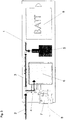
- Fig. 3 schematically shows an apparatus for measuring breath alcohol concentration BrAC, according to the present invention.
- the measuring apparatus is contained within a housing 1 and comprises a replaceable breath sample inlet tube 2 for receiving an expired breath sample from a user or test person. Arrows indicate the direction of breath flow through the measuring apparatus.
- the breath flow is led through a first channel 3 which is closed at a distal end.
- a flow meter 5 is located near the distal end of the first channel 3 and measures the instantaneous flow rate Q of the breath sample through the measuring apparatus 1.
- flow meter 5 comprises a pressure-based flow meter such as a Venturi meter, an orifice plate or equivalent in combination with a pressure sensor.
- a pressure-based flow meter such as a Venturi meter, an orifice plate or equivalent in combination with a pressure sensor.
- the flow rate Q may be measured using any suitable flow meter, e.g. mechanical, pressure-based, optical, thermal or electromagnetic.
- a sampling channel 4 Part of the breath flow is led through a sampling channel 4 and enters a fuel cell sensor 6 near a proximal end of the first channel 3.
- Any alcohol (ethanol) present in the breath sample fuels an electrochemical reaction in the fuel cell 6 which gives rise to an electric current.
- This current then is a measure of the amount of alcohol in the breath sample and represented by a fuel cell output signal FC out , normally the voltage measured across the fuel cell 6.
- the flow meter 5 and the fuel cell 6 are connected with a microcontroller 7 which comprises means for processing the measurements of the flow rate and the fuel cell voltage.
- processing incorporates finding the area under the curves of the flow rate Q and the fuel cell output signal FC out versus time.
- the area corresponds to the volume V b of the breath sample and the breath alcohol concentration BrAC, respectively. This may also be achieved by integrating the flow rate Q , and the fuel cell output signal FC out , respectively, with respect to time.
- the microcontroller 7 is adapted to continually update the breath sample volume V b and the fuel cell output signal FC out throughout the duration of the breath test.
- a battery 9 or other suitable source of energy to power the flow meter 5, the fuel cell 6 and/or the microcontroller 7.
- the measuring apparatus may further comprise display means to display the measured breath alcohol concentration BrAC and/or the blood alcohol concentration BAC.
- the blood alcohol concentration BAC may be determined from the blood-to-air partition ratio, i.e. the relation between the amount of alcohol in a given volume of breath and blood. Most breathalysers use an international standard partition ratio of 2100:1, that is, for every part alcohol in the breath there are 2100 parts alcohol in the blood.
- the alcohol measuring apparatus may be made very compact and included in a sobriety interlock device.
- interlock devices are known in the art and will not be described in detail here.
- the interlock device may comprise means for measuring the temperature, humidity and/or alcohol concentration of the breath of a user, and based on these measurements falling within permitted ranges (corresponding to the user being non-intoxicated by alcohol), the interlock device allows starting up of a vehicle or other machinery connected to the interlock device.
- the interlock device may be equipped with a microprocessor for analysing the results of the alcohol measuring apparatus and a relay electrically connected to the starter of the vehicle or machine.
- a compact and low-cost sobriety interlock device When provided with an alcohol measuring apparatus according to the present invention, a compact and low-cost sobriety interlock device may be achieved and used to control start-up of any vehicle or machine.
Description
- The present invention relates to a method for measuring breath alcohol concentration of a user, as defined by the preamble of claim 1. The method comprises receiving a flow of an expired breath sample from a user and measuring the flow rate using a pressure sensor. At the same time, the breath sample is led into a fuel cell sensor. The output signal of the fuel cell sensor is used to determine the volume of alcohol present in the breath sample, and thus the breath alcohol concentration.
- In a further aspect, the invention also relates to an apparatus for measuring breath alcohol concentration of a user, as defined by the preamble of
claim 7. The apparatus comprises sampling means for receiving an expired breath sample of a user, means for measuring the flow rate of the sample, a fuel cell sensor and a microcontroller. The microcontroller is adapted to calculate the volume of alcohol present in the breath sample, and thus the breath alcohol concentration, based on an output signal of the fuel cell sensor - Generally, there are two techniques employed for measuring the breath alcohol concentration and thereby determine a person's blood alcohol concentration. In a first method, infrared spectroscopy is used, whereby a breath sample from a person is subjected to infrared radiation. The molecules in the breath sample absorb specific frequencies, called resonant frequencies, which are characteristic to the molecules. For example the absorption by ethanol molecules gives rise to a specific infrared spectrum which may be used to determine the amount of ethanol present in the breath sample, and thus the breath alcohol concentration. Although this method gives high measuring accuracy, sensors incorporating infrared spectroscopy are expensive, which limits application in mass-produced devices.
- A second commonly used technology is based on a fuel cell sensor which converts fuel in the shape of alcohol (ethanol) to electric current in an electrochemical reaction. Fuel cell sensors have a somewhat lower accuracy than infrared spectroscopy sensors, but are much cheaper. However, fuel cell sensors require that the breath sample is of a determinable volume in order to correctly determine the breath alcohol concentration.
- Traditional fuel cell based analyser systems operate by means of a mechanical sampling system which draws a pre-specified volume of breath into the fuel cell for analysis. The mechanical means may comprise motors, solenoid valves, piston-cylinder devices, diaphragm mechanisms or push buttons connected to a pump or bellows system. In
US 6,167,746 there is disclosed an apparatus comprising an electronically controlled valve to ascertain that a requisite volume of breath is passed through a fuel cell.US 2005/0241871 discloses a sobriety interlock device comprising a pressure transducer and a solenoid valve operating independently of each other providing a variable flow of breath to a fuel cell. A microprocessor instructs the solenoid valve to remain open for a finite period of time to give a predetermined breath sample volume, and calculates an algorithmic correction factor based on pressure readings to provide a pressure compensated alcohol result. -
US2009007634 discloses a breath alcohol testing device and method with a flow sensor and at least one fuel cell sensor into which the breath is led. The alcohol concentration is obtained from the output signal of the fuel cell when a certain volume of alveolar breath has been collected, following continuous sampling and volume measurement while the blowing progresses. - The methods described in the prior art involve advanced control circuitry and complex or bulky mechanical components which introduce extra cost to the system and limit the ability to reduce the size of the system without compromising accuracy. Hence, there is a need for improved methods for measuring breath alcohol concentration with high accuracy, which allow for compact devices that may be produced at low cost.
- It is an object of the present invention to provide an improved method for measuring breath alcohol concentration with high accuracy, which allows for compact measuring devices that may be produced at low cost.
- According to the present invention, there is provided a method for determining breath alcohol concentration. The method includes the following specific measures, as defined by the characterising portion of independent claim 1. From the measured flow rate, the volume of the breath sample is calculated. Throughout the expiration of the breath sample, the breath sample volume and the volume of alcohol present in the breath sample are continually updated by integrating the measured instantaneous flow rate and the fuel cell output signal over time. If the user stops blowing, flow compensation is performed wherein the fuel cell output signal is compensated using a stored calibration volume to obtain a final compensated fuel cell output signal.
- By compensating the fuel cell output signal, the measuring accuracy of the method and apparatus is ensured, irrespective of the volume of the breath sample. Since the method does not require a predetermined breath sample volume, the mechanical sampling systems as used in the prior art become unnecessary, and the measuring apparatus may be made more compact with fewer or no moving parts. Thereby the size and cost of apparatus may be greatly reduced.
- In preferred embodiments, the method according to the present invention further comprises determining the blood alcohol concentration based on the breath alcohol concentration, and displaying the resulting blood alcohol concentration.
- In a preferred embodiment, the method according to the present invention comprises performing the compensation using the formula:

- In a further preferred embodiment, the method according to the present invention comprises preventing start-up of a vehicle if the calculated breath alcohol concentration exceeds a predetermined threshold value.
- In a further preferred embodiment, the method according to the present invention comprises, measuring the flow rate by means of a pressure-based flow meter, preferably a Venturi meter or orifice plate in combination with a pressure sensor. The pressure-based flow meter has the advantage of providing a compact component with few or no moving parts, ensuring efficient use of space in a device carrying out the method of the invention.
- According to the present invention, as defined by
independent claim 7, there is also provided an apparatus for determining breath alcohol concentration. The apparatus includes the following specific features, as defined by the characterising portion of independent claim 1. Based on the flow rate measurements, the microcontroller is adapted to calculate the volume of the breath sample. The microcontroller is further adapted to continually update the breath sample volume and the breath alcohol concentration by integrating the measured instantaneous flow rate and the fuel cell output signal over time. The microcontroller is configured to perform flow compensation on the fuel cell output signal to obtain a final compensated fuel cell output signal, if the user stops blowing. - Preferred embodiments of the apparatus according to the present invention comprise features corresponding to the method described above.
- In a preferred embodiment, a breath alcohol interlock device comprising an apparatus for determining breath alcohol concentration according to the present invention and a vehicle comprising such an interlock device are provided.
-
- Fig. 1
- is a graphical representation of a fuel cell output signal over time;
- Fig. 2
- is a flowchart illustrating the method according to the present invention; and
- Fig. 3
- is a schematic diagram of an apparatus according to the present invention.
- The invention will be further explained below through the detailed description of examples thereof and with reference to the accompanying drawings. It is to be understood that the invention should not be limited to the embodiments shown in the figures and described below, but may be varied to encompass any combination of equivalent features within the scope defined by the attached claims.
- When an expired breath sample is passed through the fuel cell of a breath alcohol measuring device, also known under the name Breathalyser® (trade mark owned by Dräger), any alcohol (ethanol) present in the breath sample is oxidised in an electrochemical reaction, which generates a measurable electrical current.
Fig. 1 shows a typical output response from a fuel cell in a graph of the output voltage versus time. The area under the curve is calculated by integrating the voltage over time, which gives a value FC that is directly proportional to the alcohol concentration in the breath. - In order to give an accurate measurement of the breath alcohol concentration (BrAC), the breathalyser must be calibrated using a sample of known alcohol concentration and volume. When subsequently performing an alcohol breath test on a test person, the breathalyser requires a pre-determined sample volume, corresponding to the one used for calibration. When the required volume is supplied, the breathalyser will compare the area under the curve of the fuel cell output signal (voltage) of the test sample with the value stored from the calibration routine and give a reading for the tested breath alcohol concentration.
- The requirement of a specific sample volume represents a major inconvenience in breathalysers known in the art. Firstly, if for example the test person has reduced lung capacity, or for some other reason is not able to provide the pre-determined volume of breath sample, a valid breath test may not be performed. Secondly, the sampling mechanism needed in a breathalyser to measure and obtain a certain chosen sample volume and to furnish it to the fuel cell (e.g. pressure sensors, valves, pumps, etc.) can be rather expensive and/or bulky, which puts a constraint on the possibilities to minimise the size of the apparatus and to reduce production costs.
- In a similar method as when measuring the fuel cell area, the volume of the breath sample can be determined by calculating the area under a curve of the volumetric flow rate of the sample versus time. The flow rate is measured using a suitable flow meter, e.g. mechanical, pressure-based, optical, thermal or electromagnetic. In a preferred embodiment of the present invention, a pressure-based flow meter is used such as a Venturi meter, orifice plate or equivalent in combination with a pressure sensor.
- Laboratory test have proven that the variation of breath volume V b correlates linearly with the fuel cell output signal FC out for any specified alcohol concentration:

- By using a measured and stored calibration volume V cal to perform a "flow" compensation of the fuel cell output signal FC out, and substituting the expression for the constant k = FCout /Vb into the corresponding equation, a compensated value for the fuel cell output signal FC comp is obtained:

- Hence, a new and inventive method of accurately measuring the breath alcohol concentration of a test person is achieved, capable of handling varied expired volumes of breath, which obviates the need for a sampling mechanism.
-
Fig. 2 shows a flowchart illustrating the method according to the present invention. In a first step S201, the user starts blowing into a measuring apparatus, typically by means of a sampling tube or pipe made of plastic or other suitable material which is cheap to produce and replaceable, to ensure hygienic conditions to the users. - As the user continues to blow into the apparatus, the flow rate Q of the expired breath sample is measured and used to calculate the volume V b of the breath sample. In step S202 the calculated breath volume V b is continually updated throughout the measuring procedure by integrating the flow rate Q over time.
- At the same time, the breath alcohol concentration BrAC is calculated from the fuel cell output signal FC out and is also continually updated in step S202 by integrating the fuel cell output signal FC out over time.
- In step S204, it is checked whether the user has stopped blowing. If that is the case, flow compensation is performed in step S205 as explained above, whereby a final compensated value for the fuel cell output signal FC comp is obtained and used to calculate a compensated breath alcohol concentration BrACcomp. This value may then be displayed to the user in step S206 and/or used to determine the blood alcohol concentration of the user.
-
Fig. 3 schematically shows an apparatus for measuring breath alcohol concentration BrAC, according to the present invention. The measuring apparatus is contained within a housing 1 and comprises a replaceable breathsample inlet tube 2 for receiving an expired breath sample from a user or test person. Arrows indicate the direction of breath flow through the measuring apparatus. The breath flow is led through afirst channel 3 which is closed at a distal end. Aflow meter 5 is located near the distal end of thefirst channel 3 and measures the instantaneous flow rate Q of the breath sample through the measuring apparatus 1. - In a preferred embodiment, flow
meter 5 comprises a pressure-based flow meter such as a Venturi meter, an orifice plate or equivalent in combination with a pressure sensor. However the flow rate Q may be measured using any suitable flow meter, e.g. mechanical, pressure-based, optical, thermal or electromagnetic. - Part of the breath flow is led through a sampling channel 4 and enters a fuel cell sensor 6 near a proximal end of the
first channel 3. Any alcohol (ethanol) present in the breath sample fuels an electrochemical reaction in the fuel cell 6 which gives rise to an electric current. This current then is a measure of the amount of alcohol in the breath sample and represented by a fuel cell output signal FC out, normally the voltage measured across the fuel cell 6. - The
flow meter 5 and the fuel cell 6 are connected with amicrocontroller 7 which comprises means for processing the measurements of the flow rate and the fuel cell voltage. In this context, processing incorporates finding the area under the curves of the flow rate Q and the fuel cell output signal FC out versus time. The area corresponds to the volume V b of the breath sample and the breath alcohol concentration BrAC, respectively. This may also be achieved by integrating the flow rate Q, and the fuel cell output signal FC out, respectively, with respect to time. Themicrocontroller 7 is adapted to continually update the breath sample volume V b and the fuel cell output signal FC out throughout the duration of the breath test. - When the breath sample has passed the fuel cell 6, it exits the housing 1 of the measuring apparatus through an
exhaust tube 8. - Also comprised in the measuring apparatus is a
battery 9 or other suitable source of energy to power theflow meter 5, the fuel cell 6 and/or themicrocontroller 7. - In a preferred embodiment of the present invention, the measuring apparatus may further comprise display means to display the measured breath alcohol concentration BrAC and/or the blood alcohol concentration BAC. The blood alcohol concentration BAC may be determined from the blood-to-air partition ratio, i.e. the relation between the amount of alcohol in a given volume of breath and blood. Most breathalysers use an international standard partition ratio of 2100:1, that is, for every part alcohol in the breath there are 2100 parts alcohol in the blood.
- The alcohol measuring apparatus according to the present invention may be made very compact and included in a sobriety interlock device. Such interlock devices are known in the art and will not be described in detail here. The interlock device may comprise means for measuring the temperature, humidity and/or alcohol concentration of the breath of a user, and based on these measurements falling within permitted ranges (corresponding to the user being non-intoxicated by alcohol), the interlock device allows starting up of a vehicle or other machinery connected to the interlock device. Further, the interlock device may be equipped with a microprocessor for analysing the results of the alcohol measuring apparatus and a relay electrically connected to the starter of the vehicle or machine.
- When provided with an alcohol measuring apparatus according to the present invention, a compact and low-cost sobriety interlock device may be achieved and used to control start-up of any vehicle or machine.
Claims (13)
- Method for measuring breath alcohol concentration (BrAC) of a user, comprising the steps of:- receiving a flow of an expired breath sample from the user;- measuring the flow rate (Q) of the breath sample;- leading the breath sample into a fuel cell sensor (6); and- calculating the breath alcohol concentration (BrAC) based on an output signal (FC out) of the fuel cell sensor (6);- calculating the volume (V b) of the breath sample based on the measured flow rate (Q);characterised by:- updating continually the calculated breath sample volume (V b) and the calculated breath alcohol concentration (BrAC) by integrating the measured instantaneous flow rate (Q) and the fuel cell output signal (FC out) over time, irrespective of the breath sample volume (V b); andwhen the user stops blowing, performing the following step before calculating the final breath alcohol concentration (BrAC):- compensating the fuel cell output signal (FC out) using a stored calibration volume (V cal) to obtain a final compensated fuel cell output signal (FC comp).
- Method according to claim 1, further comprising the step of:- determining the blood alcohol concentration (BAC) based on the breath alcohol concentration (BrAC).
- Method according to claim 2, further comprising the step of:- displaying the resulting blood alcohol concentration (BAC).
- Method according to any preceding claim, wherein said compensating is performed using the formula:

- Method according to any preceding claim, further comprising the step of:- preventing start-up of a vehicle if the calculated breath alcohol concentration (BrAC) exceeds a predetermined threshold value.
- Method according to any preceding claim, wherein the flow rate (Q) is measured by means of a pressure-based flow meter (5), preferably a Venturi meter or orifice plate in combination with a pressure sensor.
- Apparatus for measuring breath alcohol concentration (BrAC), comprising:- means (2) for receiving an expired breath sample of a user;- means (5) for measuring the flow rate (Q) of the breath sample;- a fuel cell sensor (6); and- a microcontroller (7) adapted to:- calculate the breath alcohol concentration (BrAC) based on an output signal (FC out) of the fuel cell sensor;- calculate the volume (V b) of the breath sample based on the measured flow rate (Q);characterised in that the microcontroller (7) is further adapted to:- continually update the calculated breath sample volume (V b) and the calculated breath alcohol concentration (BrAC) by integrating the measured instantaneous flow rate (Q) and the fuel cell output signal (FC out) over time, irrespective of the breath sample volume (V b); and- perform a flow compensation to obtain a final compensated fuel cell output signal (FC comp) using a stored calibration volume (V cal).
- Apparatus according to claim 7, wherein the microcontroller (7) is further adapted to determine the blood alcohol concentration (BAC) based on the breath alcohol concentration (BrAC).
- Apparatus according to claim 8, wherein the apparatus further comprises display means to display the resulting blood alcohol concentration (BAC).
- Apparatus according to any of claims 7-9, wherein said flow compensation is performed using the formula:

- Apparatus according to any of claims 7-10, wherein the means for measuring the flow rate (Q) comprises a pressure-based flow meter (5), preferably a Venturi meter, or orifice plate in combination with a pressure sensor.
- A breath alcohol interlock device comprising an apparatus according to any of claims 7-11.
- A vehicle comprising a breath alcohol interlock device according to claim 12.
Applications Claiming Priority (1)
| Application Number | Priority Date | Filing Date | Title |
|---|---|---|---|
| PCT/SE2010/051421 WO2012087187A1 (en) | 2010-12-20 | 2010-12-20 | Method for measuring breath alcohol concentration and apparatus therefor |
Publications (3)
| Publication Number | Publication Date |
|---|---|
| EP2656067A1 EP2656067A1 (en) | 2013-10-30 |
| EP2656067A4 EP2656067A4 (en) | 2017-01-11 |
| EP2656067B1 true EP2656067B1 (en) | 2020-03-25 |
Family
ID=46314215
Family Applications (1)
| Application Number | Title | Priority Date | Filing Date |
|---|---|---|---|
| EP10861122.9A Active EP2656067B1 (en) | 2010-12-20 | 2010-12-20 | Method for measuring breath alcohol concentration and apparatus therefor |
Country Status (10)
| Country | Link |
|---|---|
| US (2) | US10942168B2 (en) |
| EP (1) | EP2656067B1 (en) |
| JP (1) | JP6023075B2 (en) |
| KR (1) | KR101807802B1 (en) |
| CN (1) | CN103380374B (en) |
| CA (1) | CA2821907C (en) |
| DK (1) | DK2656067T3 (en) |
| EA (1) | EA025809B1 (en) |
| ES (1) | ES2806125T3 (en) |
| WO (1) | WO2012087187A1 (en) |
Families Citing this family (18)
| Publication number | Priority date | Publication date | Assignee | Title |
|---|---|---|---|---|
| SE537211C2 (en) * | 2012-06-19 | 2015-03-03 | Alco Systems Sweden Ab | Procedure for measuring alcohol exhalation concentration and apparatus therefore |
| SE537365C2 (en) * | 2012-06-27 | 2015-04-14 | Alco Systems Sweden Ab | Device, method and equipment for calibrating a device intended for alcohol exhalation tests |
| JP6004535B2 (en) * | 2012-12-28 | 2016-10-12 | フィガロ技研株式会社 | Gas detector |
| EP2762882B1 (en) * | 2013-01-31 | 2020-11-25 | Sensirion AG | Portable electronic device with ketone sensor |
| WO2014146714A1 (en) * | 2013-03-21 | 2014-09-25 | Barbetta Marco | Method and apparatus for detecting breath alcohol concentration based on acoustic breath sampler |
| JP6268484B2 (en) * | 2014-06-11 | 2018-01-31 | 株式会社タニタ | Biogas detection apparatus, method, and program |
| WO2015200926A1 (en) | 2014-06-27 | 2015-12-30 | Pulse Heath Llc | Fluorescence detection assembly |
| US20160022172A1 (en) * | 2014-07-23 | 2016-01-28 | Lifeloc Technologies, Inc. | Systems and methods for fluid testing |
| EP3018476A1 (en) | 2014-11-10 | 2016-05-11 | Knightsbridge Alcosystems Limited | Sobriety test authentication process and device |
| US10604011B2 (en) | 2015-10-13 | 2020-03-31 | Consumer Safety Technology, Llc | Networked intoxication vehicle immobilization |
| US10877008B2 (en) | 2016-09-09 | 2020-12-29 | Consumer Safety Technology, Llc | Reference gas management in a breath alcohol calibration station |
| US10663440B2 (en) | 2016-09-09 | 2020-05-26 | Consumer Safety Technology, Llc | Secure data handling in a breath alcohol calibration station |
| US20180174486A1 (en) * | 2016-12-21 | 2018-06-21 | GM Global Technology Operations LLC | Impairment detection device with performance feedback system and method of operating the same |
| US11022599B2 (en) * | 2017-08-16 | 2021-06-01 | Breathalytics, LLC | Self-regulating alcohol breathalyzer |
| DE102017008008A1 (en) | 2017-08-25 | 2019-02-28 | Dräger Safety AG & Co. KGaA | Breath alcohol measurement with non-contact sample dispensing |
| KR102030278B1 (en) * | 2018-06-07 | 2019-10-10 | (주)센텍코리아 | Breath alcohol analyzer for low range concentration |
| KR102531358B1 (en) * | 2021-04-07 | 2023-05-15 | (주)센텍코리아 | Breath alcohol analyzer |
| US20220401308A1 (en) * | 2021-06-18 | 2022-12-22 | Lenore Everson | Methods and devices for dispensing medication |
Family Cites Families (33)
| Publication number | Priority date | Publication date | Assignee | Title |
|---|---|---|---|---|
| US4363635A (en) * | 1981-01-26 | 1982-12-14 | Cal Detect, Inc. | Method and apparatus for measuring breath alcohol |
| DE3119341A1 (en) | 1981-05-15 | 1982-12-02 | Sachs Systemtechnik Gmbh, 8720 Schweinfurt | Breath alcohometer |
| US4459994A (en) | 1982-06-23 | 1984-07-17 | Siemens Aktiengesellschaft | Method for assuring valid measured values of breath alcohol concentration |
| US4770026A (en) * | 1987-01-15 | 1988-09-13 | Alcotek, Inc. | Method of and apparatus for testing breath alcohol |
| GB8711573D0 (en) * | 1987-05-15 | 1987-06-17 | Lion Lab Ltd | Measuring apparatus |
| US4902628A (en) * | 1988-08-24 | 1990-02-20 | Guardian Technologies, Inc. | Apparatus and method to deter circumvention of a breath sobriety test |
| DE4344196C2 (en) | 1993-12-23 | 1997-08-07 | Draegerwerk Ag | Method for determining parameters of an electrochemically convertible substance in a gas sample |
| US6026674A (en) * | 1998-08-20 | 2000-02-22 | Smart Start Inc. | Apparatus and method for determining a person's sobriety |
| DE10030053A1 (en) * | 2000-06-19 | 2002-01-10 | Envitec Wismar Gmbh | Atemalkoholmeßgerät |
| US6550310B1 (en) * | 2000-11-28 | 2003-04-22 | Honeywell International Inc. | Catalytic adsorption and oxidation based carbon monoxide sensor and detection method |
| CA2366909A1 (en) * | 2002-01-03 | 2003-07-03 | Envitec-Wismar Gmbh | Device and method for measuring alcohol vapour concentration |
| IL148468A (en) * | 2002-03-03 | 2012-12-31 | Exalenz Bioscience Ltd | Breath collection system |
| US20050251060A1 (en) * | 2002-03-14 | 2005-11-10 | Edward Gollar | Methods of detecting gaseous component levels in a breath |
| US20030176803A1 (en) * | 2002-03-14 | 2003-09-18 | Edward Gollar | Personal breath tester |
| US6792793B2 (en) * | 2002-03-28 | 2004-09-21 | Ignition Lock International | Breath measurement instrument and breath alcohol interlock device incorporating same |
| US7749169B2 (en) * | 2003-04-10 | 2010-07-06 | Intoximeters, Inc. | Handheld breath tester housing and mouthpiece |
| US7878980B2 (en) * | 2003-06-13 | 2011-02-01 | Treymed, Inc. | Gas flow diverter for respiratory monitoring device |
| CA2538604C (en) * | 2003-09-19 | 2013-04-23 | Intoximeters, Inc. | Methods and apparatus for breath alcohol testing |
| US7422723B1 (en) * | 2003-10-24 | 2008-09-09 | Alcohol Detection Systems, Inc. | Alcohol breath test device |
| EP1678001B1 (en) | 2003-10-31 | 2018-11-21 | Guardian Interlock, LLC | Vehicle sobriety interlock device |
| JP4570971B2 (en) * | 2005-01-24 | 2010-10-27 | 日本電信電話株式会社 | Alcohol checker and alcohol detection method |
| CA2552130A1 (en) * | 2005-07-15 | 2007-01-15 | Omegapoint Systems, Llc | Methods of detecting gaseous component levels in a breath |
| JP5405118B2 (en) * | 2005-11-29 | 2014-02-05 | アルコ、システムズ、スウェーデン、アクチボラグ | System and method for determining the time when blood alcohol concentration passes a threshold level |
| US20070273537A1 (en) * | 2006-04-18 | 2007-11-29 | Dolphin International Resources, Llc, | Combined system for tracking offender rehabilitation |
| DE102006018970B3 (en) * | 2006-04-25 | 2007-05-03 | Dräger Safety AG & Co. KGaA | Breath alcohol measuring instrument e.g. for alcohol in breath, has evaluation and control unit receiving measuring signals of sensors and operates sampling system which has bellows and piezo actuator |
| FR2906450B3 (en) * | 2006-09-29 | 2009-04-24 | Nellcor Puritan Bennett Incorp | SYSTEM AND METHOD FOR DETECTING RESPIRATORY EVENTS |
| SE531742C2 (en) * | 2007-02-01 | 2009-07-28 | Hoek Instr Ab | Interactive alcometry |
| WO2009006637A2 (en) * | 2007-07-05 | 2009-01-08 | Alcotek Inc. | Mouth alcohol tester |
| US8657757B2 (en) * | 2007-07-26 | 2014-02-25 | Pulmone Advanced Medical Devices, Ltd. | System and methods for the measurement of lung volumes |
| JP5141524B2 (en) * | 2008-12-10 | 2013-02-13 | トヨタ自動車株式会社 | Gas component detector |
| CN201488975U (en) * | 2009-02-27 | 2010-05-26 | 陈新 | Multi-module detachable expired gas alcoholicity tester |
| CN102803943B (en) * | 2009-04-15 | 2016-03-16 | 纳诺米克斯公司 | Breathe condensed fluid sampler and detecting device and breathing/breathing condensed fluid sampler and detecting device |
| US9272105B2 (en) * | 2010-07-09 | 2016-03-01 | New York University | System and method for diagnosis and treatment of obstructive sleep apnea |
-
2010
- 2010-12-20 US US13/995,377 patent/US10942168B2/en active Active
- 2010-12-20 EA EA201390860A patent/EA025809B1/en not_active IP Right Cessation
- 2010-12-20 JP JP2013546067A patent/JP6023075B2/en not_active Expired - Fee Related
- 2010-12-20 ES ES10861122T patent/ES2806125T3/en active Active
- 2010-12-20 CA CA2821907A patent/CA2821907C/en active Active
- 2010-12-20 DK DK10861122.9T patent/DK2656067T3/en active
- 2010-12-20 WO PCT/SE2010/051421 patent/WO2012087187A1/en active Application Filing
- 2010-12-20 KR KR1020137017975A patent/KR101807802B1/en active IP Right Grant
- 2010-12-20 CN CN201080071238.3A patent/CN103380374B/en active Active
- 2010-12-20 EP EP10861122.9A patent/EP2656067B1/en active Active
-
2021
- 2021-03-04 US US17/192,147 patent/US11885795B2/en active Active
Non-Patent Citations (1)
| Title |
|---|
| None * |
Also Published As
| Publication number | Publication date |
|---|---|
| JP2014507632A (en) | 2014-03-27 |
| CN103380374B (en) | 2014-07-30 |
| US10942168B2 (en) | 2021-03-09 |
| US11885795B2 (en) | 2024-01-30 |
| CA2821907C (en) | 2019-06-11 |
| US20130281873A1 (en) | 2013-10-24 |
| ES2806125T3 (en) | 2021-02-16 |
| JP6023075B2 (en) | 2016-11-09 |
| DK2656067T3 (en) | 2020-07-06 |
| EA025809B1 (en) | 2017-01-30 |
| WO2012087187A1 (en) | 2012-06-28 |
| CA2821907A1 (en) | 2012-06-28 |
| EP2656067A4 (en) | 2017-01-11 |
| EP2656067A1 (en) | 2013-10-30 |
| US20210270804A1 (en) | 2021-09-02 |
| KR101807802B1 (en) | 2018-01-18 |
| CN103380374A (en) | 2013-10-30 |
| KR20130129405A (en) | 2013-11-28 |
| EA201390860A1 (en) | 2014-01-30 |
Similar Documents
| Publication | Publication Date | Title |
|---|---|---|
| US11885795B2 (en) | Method for measuring breath alcohol concentration and apparatus therefor | |
| EP2861983B1 (en) | Method for measuring breath alcohol concentration and apparatus therefor | |
| JP5921562B2 (en) | Multifunction breath analyzer | |
| CN101368927B (en) | Self-calibration gas sensor | |
| US20060016244A1 (en) | Engagement of a sensor system with a vehicle operating device | |
| RU2586773C2 (en) | Cartridge with standard alcohol gas for breathalyser | |
| KR102330982B1 (en) | Breath alcohol analyzer with exhalation temperature measurement function | |
| CN112782410B (en) | Dynamic calibration method of quick-discharge wine detector and detector | |
| WO2022024011A1 (en) | A fluid measurement chamber | |
| KR102531358B1 (en) | Breath alcohol analyzer | |
| CA2552130A1 (en) | Methods of detecting gaseous component levels in a breath | |
| JPH09325115A (en) | Infrared gas detector |
Legal Events
| Date | Code | Title | Description |
|---|---|---|---|
| PUAI | Public reference made under article 153(3) epc to a published international application that has entered the european phase |
Free format text: ORIGINAL CODE: 0009012 |
|
| 17P | Request for examination filed |
Effective date: 20130722 |
|
| AK | Designated contracting states |
Kind code of ref document: A1 Designated state(s): AL AT BE BG CH CY CZ DE DK EE ES FI FR GB GR HR HU IE IS IT LI LT LU LV MC MK MT NL NO PL PT RO RS SE SI SK SM TR |
|
| DAX | Request for extension of the european patent (deleted) | ||
| RA4 | Supplementary search report drawn up and despatched (corrected) |
Effective date: 20161209 |
|
| RIC1 | Information provided on ipc code assigned before grant |
Ipc: B60K 28/06 20060101ALI20161205BHEP Ipc: G01N 1/22 20060101ALI20161205BHEP Ipc: G01N 33/98 20060101ALI20161205BHEP Ipc: G01N 33/497 20060101AFI20161205BHEP |
|
| GRAP | Despatch of communication of intention to grant a patent |
Free format text: ORIGINAL CODE: EPIDOSNIGR1 |
|
| STAA | Information on the status of an ep patent application or granted ep patent |
Free format text: STATUS: GRANT OF PATENT IS INTENDED |
|
| INTG | Intention to grant announced |
Effective date: 20191017 |
|
| GRAS | Grant fee paid |
Free format text: ORIGINAL CODE: EPIDOSNIGR3 |
|
| GRAA | (expected) grant |
Free format text: ORIGINAL CODE: 0009210 |
|
| STAA | Information on the status of an ep patent application or granted ep patent |
Free format text: STATUS: THE PATENT HAS BEEN GRANTED |
|
| AK | Designated contracting states |
Kind code of ref document: B1 Designated state(s): AL AT BE BG CH CY CZ DE DK EE ES FI FR GB GR HR HU IE IS IT LI LT LU LV MC MK MT NL NO PL PT RO RS SE SI SK SM TR |
|
| REG | Reference to a national code |
Ref country code: GB Ref legal event code: FG4D |
|
| REG | Reference to a national code |
Ref country code: AT Ref legal event code: REF Ref document number: 1249140 Country of ref document: AT Kind code of ref document: T Effective date: 20200415 Ref country code: IE Ref legal event code: FG4D |
|
| REG | Reference to a national code |
Ref country code: DE Ref legal event code: R096 Ref document number: 602010063687 Country of ref document: DE |
|
| REG | Reference to a national code |
Ref country code: FI Ref legal event code: FGE |
|
| REG | Reference to a national code |
Ref country code: DK Ref legal event code: T3 Effective date: 20200629 |
|
| REG | Reference to a national code |
Ref country code: SE Ref legal event code: TRGR |
|
| RAP2 | Party data changed (patent owner data changed or rights of a patent transferred) |
Owner name: ALCO SYSTEMS SWEDEN AB |
|
| PG25 | Lapsed in a contracting state [announced via postgrant information from national office to epo] |
Ref country code: RS Free format text: LAPSE BECAUSE OF FAILURE TO SUBMIT A TRANSLATION OF THE DESCRIPTION OR TO PAY THE FEE WITHIN THE PRESCRIBED TIME-LIMIT Effective date: 20200325 |
|
| REG | Reference to a national code |
Ref country code: SE Ref legal event code: RPOT |
|
| REG | Reference to a national code |
Ref country code: NO Ref legal event code: T2 Effective date: 20200325 |
|
| PG25 | Lapsed in a contracting state [announced via postgrant information from national office to epo] |
Ref country code: GR Free format text: LAPSE BECAUSE OF FAILURE TO SUBMIT A TRANSLATION OF THE DESCRIPTION OR TO PAY THE FEE WITHIN THE PRESCRIBED TIME-LIMIT Effective date: 20200626 Ref country code: BG Free format text: LAPSE BECAUSE OF FAILURE TO SUBMIT A TRANSLATION OF THE DESCRIPTION OR TO PAY THE FEE WITHIN THE PRESCRIBED TIME-LIMIT Effective date: 20200625 Ref country code: LV Free format text: LAPSE BECAUSE OF FAILURE TO SUBMIT A TRANSLATION OF THE DESCRIPTION OR TO PAY THE FEE WITHIN THE PRESCRIBED TIME-LIMIT Effective date: 20200325 Ref country code: HR Free format text: LAPSE BECAUSE OF FAILURE TO SUBMIT A TRANSLATION OF THE DESCRIPTION OR TO PAY THE FEE WITHIN THE PRESCRIBED TIME-LIMIT Effective date: 20200325 |
|
| REG | Reference to a national code |
Ref country code: NL Ref legal event code: MP Effective date: 20200325 |
|
| REG | Reference to a national code |
Ref country code: LT Ref legal event code: MG4D |
|
| REG | Reference to a national code |
Ref country code: EE Ref legal event code: FG4A Ref document number: E019495 Country of ref document: EE Effective date: 20200630 |
|
| PG25 | Lapsed in a contracting state [announced via postgrant information from national office to epo] |
Ref country code: NL Free format text: LAPSE BECAUSE OF FAILURE TO SUBMIT A TRANSLATION OF THE DESCRIPTION OR TO PAY THE FEE WITHIN THE PRESCRIBED TIME-LIMIT Effective date: 20200325 |
|
| PG25 | Lapsed in a contracting state [announced via postgrant information from national office to epo] |
Ref country code: RO Free format text: LAPSE BECAUSE OF FAILURE TO SUBMIT A TRANSLATION OF THE DESCRIPTION OR TO PAY THE FEE WITHIN THE PRESCRIBED TIME-LIMIT Effective date: 20200325 Ref country code: LT Free format text: LAPSE BECAUSE OF FAILURE TO SUBMIT A TRANSLATION OF THE DESCRIPTION OR TO PAY THE FEE WITHIN THE PRESCRIBED TIME-LIMIT Effective date: 20200325 Ref country code: SM Free format text: LAPSE BECAUSE OF FAILURE TO SUBMIT A TRANSLATION OF THE DESCRIPTION OR TO PAY THE FEE WITHIN THE PRESCRIBED TIME-LIMIT Effective date: 20200325 Ref country code: PT Free format text: LAPSE BECAUSE OF FAILURE TO SUBMIT A TRANSLATION OF THE DESCRIPTION OR TO PAY THE FEE WITHIN THE PRESCRIBED TIME-LIMIT Effective date: 20200818 Ref country code: SK Free format text: LAPSE BECAUSE OF FAILURE TO SUBMIT A TRANSLATION OF THE DESCRIPTION OR TO PAY THE FEE WITHIN THE PRESCRIBED TIME-LIMIT Effective date: 20200325 Ref country code: IS Free format text: LAPSE BECAUSE OF FAILURE TO SUBMIT A TRANSLATION OF THE DESCRIPTION OR TO PAY THE FEE WITHIN THE PRESCRIBED TIME-LIMIT Effective date: 20200725 Ref country code: CZ Free format text: LAPSE BECAUSE OF FAILURE TO SUBMIT A TRANSLATION OF THE DESCRIPTION OR TO PAY THE FEE WITHIN THE PRESCRIBED TIME-LIMIT Effective date: 20200325 |
|
| REG | Reference to a national code |
Ref country code: AT Ref legal event code: MK05 Ref document number: 1249140 Country of ref document: AT Kind code of ref document: T Effective date: 20200325 |
|
| REG | Reference to a national code |
Ref country code: DE Ref legal event code: R097 Ref document number: 602010063687 Country of ref document: DE |
|
| PG25 | Lapsed in a contracting state [announced via postgrant information from national office to epo] |
Ref country code: AT Free format text: LAPSE BECAUSE OF FAILURE TO SUBMIT A TRANSLATION OF THE DESCRIPTION OR TO PAY THE FEE WITHIN THE PRESCRIBED TIME-LIMIT Effective date: 20200325 |
|
| PLBE | No opposition filed within time limit |
Free format text: ORIGINAL CODE: 0009261 |
|
| STAA | Information on the status of an ep patent application or granted ep patent |
Free format text: STATUS: NO OPPOSITION FILED WITHIN TIME LIMIT |
|
| REG | Reference to a national code |
Ref country code: ES Ref legal event code: FG2A Ref document number: 2806125 Country of ref document: ES Kind code of ref document: T3 Effective date: 20210216 |
|
| PG25 | Lapsed in a contracting state [announced via postgrant information from national office to epo] |
Ref country code: PL Free format text: LAPSE BECAUSE OF FAILURE TO SUBMIT A TRANSLATION OF THE DESCRIPTION OR TO PAY THE FEE WITHIN THE PRESCRIBED TIME-LIMIT Effective date: 20200325 |
|
| 26N | No opposition filed |
Effective date: 20210112 |
|
| PG25 | Lapsed in a contracting state [announced via postgrant information from national office to epo] |
Ref country code: SI Free format text: LAPSE BECAUSE OF FAILURE TO SUBMIT A TRANSLATION OF THE DESCRIPTION OR TO PAY THE FEE WITHIN THE PRESCRIBED TIME-LIMIT Effective date: 20200325 |
|
| REG | Reference to a national code |
Ref country code: CH Ref legal event code: PL |
|
| PG25 | Lapsed in a contracting state [announced via postgrant information from national office to epo] |
Ref country code: MC Free format text: LAPSE BECAUSE OF FAILURE TO SUBMIT A TRANSLATION OF THE DESCRIPTION OR TO PAY THE FEE WITHIN THE PRESCRIBED TIME-LIMIT Effective date: 20200325 |
|
| REG | Reference to a national code |
Ref country code: BE Ref legal event code: MM Effective date: 20201231 |
|
| PG25 | Lapsed in a contracting state [announced via postgrant information from national office to epo] |
Ref country code: LU Free format text: LAPSE BECAUSE OF NON-PAYMENT OF DUE FEES Effective date: 20201220 Ref country code: IE Free format text: LAPSE BECAUSE OF NON-PAYMENT OF DUE FEES Effective date: 20201220 |
|
| PG25 | Lapsed in a contracting state [announced via postgrant information from national office to epo] |
Ref country code: CH Free format text: LAPSE BECAUSE OF NON-PAYMENT OF DUE FEES Effective date: 20201231 Ref country code: LI Free format text: LAPSE BECAUSE OF NON-PAYMENT OF DUE FEES Effective date: 20201231 |
|
| PG25 | Lapsed in a contracting state [announced via postgrant information from national office to epo] |
Ref country code: MT Free format text: LAPSE BECAUSE OF FAILURE TO SUBMIT A TRANSLATION OF THE DESCRIPTION OR TO PAY THE FEE WITHIN THE PRESCRIBED TIME-LIMIT Effective date: 20200325 Ref country code: CY Free format text: LAPSE BECAUSE OF FAILURE TO SUBMIT A TRANSLATION OF THE DESCRIPTION OR TO PAY THE FEE WITHIN THE PRESCRIBED TIME-LIMIT Effective date: 20200325 |
|
| PG25 | Lapsed in a contracting state [announced via postgrant information from national office to epo] |
Ref country code: MK Free format text: LAPSE BECAUSE OF FAILURE TO SUBMIT A TRANSLATION OF THE DESCRIPTION OR TO PAY THE FEE WITHIN THE PRESCRIBED TIME-LIMIT Effective date: 20200325 Ref country code: AL Free format text: LAPSE BECAUSE OF FAILURE TO SUBMIT A TRANSLATION OF THE DESCRIPTION OR TO PAY THE FEE WITHIN THE PRESCRIBED TIME-LIMIT Effective date: 20200325 |
|
| PG25 | Lapsed in a contracting state [announced via postgrant information from national office to epo] |
Ref country code: BE Free format text: LAPSE BECAUSE OF NON-PAYMENT OF DUE FEES Effective date: 20201231 |
|
| PGFP | Annual fee paid to national office [announced via postgrant information from national office to epo] |
Ref country code: ES Payment date: 20230103 Year of fee payment: 13 |
|
| P01 | Opt-out of the competence of the unified patent court (upc) registered |
Effective date: 20230525 |
|
| PGFP | Annual fee paid to national office [announced via postgrant information from national office to epo] |
Ref country code: GB Payment date: 20231220 Year of fee payment: 14 |
|
| PGFP | Annual fee paid to national office [announced via postgrant information from national office to epo] |
Ref country code: TR Payment date: 20231127 Year of fee payment: 14 Ref country code: SE Payment date: 20231219 Year of fee payment: 14 Ref country code: NO Payment date: 20231206 Year of fee payment: 14 Ref country code: IT Payment date: 20231227 Year of fee payment: 14 Ref country code: FR Payment date: 20231220 Year of fee payment: 14 Ref country code: FI Payment date: 20231130 Year of fee payment: 14 Ref country code: EE Payment date: 20231128 Year of fee payment: 14 Ref country code: DK Payment date: 20231227 Year of fee payment: 14 Ref country code: DE Payment date: 20231214 Year of fee payment: 14 |
|
| PGFP | Annual fee paid to national office [announced via postgrant information from national office to epo] |
Ref country code: ES Payment date: 20240103 Year of fee payment: 14 |