EP2655976B1 - Gargerät mit wrasenabzugseinrichtung - Google Patents
Gargerät mit wrasenabzugseinrichtung Download PDFInfo
- Publication number
- EP2655976B1 EP2655976B1 EP11794182.3A EP11794182A EP2655976B1 EP 2655976 B1 EP2655976 B1 EP 2655976B1 EP 11794182 A EP11794182 A EP 11794182A EP 2655976 B1 EP2655976 B1 EP 2655976B1
- Authority
- EP
- European Patent Office
- Prior art keywords
- cooking appliance
- vapour
- adjustment element
- valve
- vapor
- Prior art date
- Legal status (The legal status is an assumption and is not a legal conclusion. Google has not performed a legal analysis and makes no representation as to the accuracy of the status listed.)
- Active
Links
Images



Classifications
-
- F—MECHANICAL ENGINEERING; LIGHTING; HEATING; WEAPONS; BLASTING
- F24—HEATING; RANGES; VENTILATING
- F24C—DOMESTIC STOVES OR RANGES ; DETAILS OF DOMESTIC STOVES OR RANGES, OF GENERAL APPLICATION
- F24C15/00—Details
- F24C15/20—Removing cooking fumes
- F24C15/2007—Removing cooking fumes from oven cavities
Definitions
- the invention relates to a cooking appliance with a Wrasenabppings worn, the Wrasenabppings worn has at least one depending on a degree of moisture of Wrasens automatically adjustable armature.
- Out EP 0 598 211 B1 is an oven, in particular with a device for a pyrolytic self-cleaning, known with a provided in an oven wall Wrasenö réelle through which the fumes produced in oven operation can flow outward, the flow cross section of the Wrasenö réelle itself or a subsequent flow channel by a throttle automatically adjustable is, wherein the adjusting movement of the throttle as a function of the temperature of Wrasens takes place, which choke forms a large flow cross-section with low heat development in the oven and decreases or closes the flow cross-section with strong heat.
- the adjustment of the throttle can also be done in dependence on the moisture of the Wrasens.
- the object is achieved by a cooking appliance with a vapor extraction device, wherein the vapor extraction device has at least one depending on a moisture level of Wrasens automatically adjustable valve.
- the valve has at least one adjusting element for its adjustment, the length of which changes as a function of the degree of humidity or the relative humidity.
- the use of such a fitting has the advantage that it allows a simple and flexibly ausgestaltetbaren structure, eg by a direct linear actuation of the valve.
- the actuation by a change in length of the at least one adjusting element further allows a comparatively tolerant and error-less adjustment.
- the vapor extraction device can be any device which is designed to remove vapors from a cooking chamber, in particular to suck it off, typically from the cooking appliance.
- the vapor extraction device can have and / or connect to an inlet opening opening into a cooking chamber of the cooking appliance.
- One or more channels of vapor can be connected to the inlet opening for passing the vapor outwards.
- the vapor extraction device may further comprise at least one opening into a vapor duct air supply opening to cool the vapor and / or adjust a volume flow of Wrasens.
- the vapor extraction device may also have a fan or a fan for moving the Wrasens in the at least one vapor channel.
- a valve can be understood in particular any type of valve, which serve to adjust, control or regulation of currents in the vapor extraction device or in at least one Wrasenkanal thereof.
- a fitting may in particular comprise a flap, a slide or a shut-off valve as an active element or closing element which can be adjusted by the adjusting element.
- the adjusting element can in particular change its length depending on the degree of moisture of the moisture acting on it. It is a development that the at least one adjusting element is hygroscopic and swells depending on the degree of moisture. The adjusting element can in particular continue to expand with increasing moisture level and contract with decreasing moisture level, in particular in a longitudinal direction.
- At least one adjusting element is arranged in a region of the vapor extraction device which can be acted upon by vapors. This allows a compact and secure arrangement. Alternatively, the adjustment can be accommodated for example in a cooking chamber of the cooking appliance.
- the adjusting element comprises a plastic band.
- the plastic band has the advantage that it occupies a small volume and thus does not significantly affect a flow cross-section.
- the plastic strap can easily be laid over longer distances and can also be deflected. If the plastic tape is passed through a wall or similar partition, only a small Passage opening required.
- the plastic band is relatively inexpensive.
- the plastic strip may in particular comprise a plurality of individual fibers, which each have hygroscopic properties.
- a plastic tape is known, for example, under the name "Polyga” as a moisture measuring element of Hygromoduls HM120 the company Galltec Mess- und Regeltechnik GmbH.
- the Hygromodul HM120 is a humidity-dependent switch, which represents a two-position controller with changeover contact.
- the moisture measuring element here consists of several plastic fabric tapes each with 90 hygroscopic individual fibers, each with a diameter of 3 ⁇ m.
- the moisture sensing element absorbs and desorbs moisture.
- the mainly longitudinally swelling effect is supplied in the Hygromodul HM120 via a lever system a microswitch with a small switching path.
- the plastic band is elastic and thus constitutes a spring element, it may change its spring constant, in particular as a function of the degree of moisture.
- the adjusting element is a pressure-resistant adjusting element.
- the use of the pressure-resistant adjusting element has the advantage that this can also use its change in length to an adjustment of the valve under pressure, e.g. for pressing a closure element.
- the pressure-resistant adjusting element can comprise, for example, a, in particular hygroscopic, plastic rod, alternatively a length-expandable housing with a hygroscopic filler or a lever element connected to a hygroscopic belt, etc.
- the adjustment is not limited to a use of plastic.
- the fitting is arranged and arranged to adjust a flow cross-section in the region of an opening into a cooking chamber of the cooking appliance inlet opening.
- the inlet opening can be at least partially covered or covered by means of the fitting or its closure element.
- This embodiment has the advantage that a flow volume through the vapor extraction device can be changed in a structurally simple manner, wherein a construction space of the vapor extraction device can be kept comparatively small.
- the closure element may be at least partially in the cooking chamber of the cooking appliance and be more or less spent in front of the inlet opening.
- valve in its closed position allows a (small) side stream.
- the adjusting element and the closure element are arranged in fluid flow in series, for example with the adjusting element in front of or behind the closure element, the adjusting element is continuously overflowed with the vapor and can thus react continuously to a varying degree of humidity.
- the fitting has a small flow cross-section in the region of the inlet opening. In its closed position, the valve does not completely close the vapor extraction device, but allows a small stream of vapor.
- the fitting is arranged and arranged to adjust a flow cross section in the region of an opening into a cooking chamber of the cooking appliance inlet opening, can be achieved,
- valve is set up and arranged to adjust a flow cross-section in at least one vapor channel of the vapor extraction device.
- the fitting is arranged and arranged to adjust a flow cross-section of an opening into a vapor duct air supply opening.
- additional air (“cooling air”) is introduced from the outside into the vapor channel, wherein a volume flow of Wrasens or a mixture of the volume flow of cooling air and vapor is adjustable by a variation of the flow cross section of the air supply opening and / or whereby the Wrasen downstream of the Air supply is coolable.
- the adjusting element is arranged in a Wrasenkanal the Wrasenabzugs noticed. For example, it is particularly easy to move past the adjustment element in terms of design.
- the adjusting element in a e.g. is arranged by outside cooling air flowing past, coolable vapor side channel.
- an ambient temperature at the adjusting element can be reduced in comparison to an arrangement in the (main) vapor channel, which for example reduces the risk of damage to the adjusting element and allows an extension of a service life.
- the adjusting element is arranged in a at least fluidly connected to a Wrasenkanal measuring chamber. This provides the advantage that the adjustment element is better protected against excessive temperatures and contamination (e.g., by entrained food particles or oil, etc.).
- valve has an operable by the adjustment flap (as the closure element).
- the flap may for example be a particular centric butterfly valve.
- the adjusting element comprises a band, in particular plastic band, which can actuate a flap that the e.g. Plastic tape is attached to the flap and the valve has at least one attached to the flap, the plastic strap exciting counter-element, in particular spring or weight.
- a position (including a rotational position) of the valve or its closure element with the plastic band can be easily and precisely adjusted and adjusted.
- valve has at least one temperature compensation element to compensate for a temperature-dependent change in length of the adjustment.
- an adjustment of the valve or its closure element can be performed very precisely depending on the degree of moisture.
- the temperature compensation element has at least one bimetallic strip.
- the bimetallic strip is inexpensive, robust and sufficiently precise for temperature compensation.
- the bimetallic strip may be configured and arranged to vary a bias of the plastic tape (or other moisture-dependent length-changing tape) depending on the temperature.
- the bimetal strip can consequently be designed in its length and combination of materials so that it compensates for the influence of temperature on the plastic strip.
- the influence of temperature on the plastic strip can be compensated by the coupling by means of a compensating component, which exhibits a temperature expansion.
- a compensating component which exhibits a temperature expansion.
- a lever mechanism for vapor control may consist of different temperature-dependent materials.
- the cooking appliance may be, but is not limited to, an oven, a microwave oven, or a combination thereof.
- the cooking appliance may in particular have a pyrolysis function.
- Fig.1 shows a sectional side view of a sketch of a cooking appliance 101 according to a first embodiment in the form of a baking oven.
- the cooking appliance 101 has a cooking appliance muffle 102, which encloses a heatable cooking space 104 together with a door 103.
- food to be cooked G wherein the food G typically W exhausts vapor.
- the vapor W is conveyed via a vapor extraction device 105 from the oven 104 to the outside.
- the vapor extraction device 105 has a vapor passage 106 extending from the cooking chamber 104 to the outside, in which a fan 107 is located.
- an inlet opening 109 for sucking the Wrasens W in the vapor channel 106 is located on the ceiling of the cooking chamber 104, an inlet opening 109 for sucking the Wrasens W in the vapor channel 106.
- the inlet opening 109 is formed by a tubular nozzle 110 which projects into the cooking chamber 104.
- the socket 110 has a lateral recess 111.
- the cooking appliance 101 further comprises a fitting 112 for at least partially covering the inlet opening 109.
- the fitting 112 has a closure element in the form of a rotatable flap 113 running through a wall of the vapor channel 106 and through a cover of the cooking appliance muffle 102.
- the flap 113 is like a lever around a pivot D rotatable.
- the flap 113 is biased (eg, by a spring member) such that the bias urges the flap 113 away from the socket 110 to an open position.
- the inlet opening 109 is not completely closed, but it can still occur through the recess 111 Wrasen W, but with only a small, a state in the cooking chamber 104 or an operating sequence (eg cooking or pyrolysis) or only slightly influencing volume flow ,
- the flap 113 is connected to an adjusting element 114 located in the vapor channel 106, the length of which changes depending on a degree of humidity or relative humidity.
- the adjusting element 114 is fastened at one end to the flap 113 at a location which, in relation to the rotary joint D, is opposite the region covering the socket 110.
- the adjusting element 114 is attached with its other end to a fixed fastening element 115.
- the adjusting element 114 is in the form of a hygroscopic plastic strip, which swells more at elevated humidity and thus expands more. Due to the bias of the flap 113, the adjusting element 114 remains permanently tensioned, so that the rotational position of the flap 113 is precisely defined.
- the adjusting element 114 contracts with dry vapor W or dry air.
- the Wrasenabzugs adopted 105 is virtually closed against the bias relative to the cooking chamber 104, which allows for a cooking operation energy-saving heating of the cooking chamber 104 and in a pyrolysis operation, the achievement of high temperatures in the cooking chamber 104.
- the passing through the recess 111 to the adjusting element 114 fumes is sufficient to detect a moisture of the air or the Wrasens W there. If the degree of humidity of the air or vapor W is or becomes higher, the adjusting element 114 swells and expands in its longitudinal direction. As a result of the prestressing, the adjusting element 114 lifts off from the inlet opening 109, which causes greater ventilation by the vapor extraction device 105.
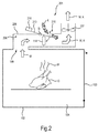
- Fig.2 shows a sectional side view of a sketch of a cooking device 201 according to a second embodiment.
- the cooking appliance 201 differs from the cooking appliance 101, inter alia in that now the inlet opening 109 is not partially closed or partially covered, but for adjusting a volume flow of Wrasens by opening into the vapor channel 206 air supply opening 215 is present.
- air supply opening 215 located upstream or upstream of the fan 107, air (“cooling air") K is absorbed from the outside into the vapor channel 206 and displaces the vapor. This reduces a volume flow of Wrasens.
- the air supply opening 215 is closed by means of a flap 213, which is pivotable about a pivot D around.
- the flap 213 On one side of the rotary joint D on its side facing the vapor channel 206, the flap 213 is connected to the adjusting element 114 in the form of the plastic strip.
- the adjusting element 114 is also located here in the vapor channel 206.
- the flap 213 of the other side of the rotary joint D is weighted with a weight 216. If the vapor W is comparatively dry, the adjusting element 114 has a small length and holds the flap 213 in a position which opens the air feed opening 215, an effective flow cross section through the air feed opening 215 being determined by the length of the adjusting element 114. If the vapor W is moist, the adjusting element 114 is expanded and can close the air supply opening 215 above a predetermined humidity or relative humidity of the vapor W, so that the vapor W can be discharged at a high volume flow.
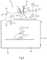
- FIG 3 shows a sectional view in side view of a sketch of a Wrasenabzugs worn 305 a cooking appliance 301.
- the Wrasenabppings worn 305 is similar to the Wrasenabppings worn 205 constructed, but now has instead of the weight 216 a tension spring 317 for biasing the adjustment 114 on.
- the tension spring 317 is here for example attached to the same arm of the flap 313 as the adjusting element 114, but on the side remote from the Wrasenkanal 306 outside.
- the other end of the tension spring 317 may be attached to a housing 318, for example.
- FIG. 4 shows a sectional side view of a sketch of a cooking appliance 401 according to a fourth embodiment.
- the cooking appliance 401 now has a vapor extraction device 405, which has a cooling air channel 419 with a fixed configuration. Of the Cooling air passage 419 merges with the vapor passage 406 in front of the blower 107.
- the vapor passage 406 branches behind the inlet opening 109 into a first branch or main passage 421 and a second branch or sub-passage 422.
- the main passage 421 and the sub-passage 422 are separated by a partition wall 423 separated.
- the secondary channel 422 may, in particular, have a smaller flow cross section than the main channel 421.
- the main channel 421 and the secondary channel 422 unite to form a single channel section or header channel 424 prior to union with the cooling air channel 419.
- the flap 413 is located in the main well channel 421, while the adjustment element 114 is located in the auxiliary channel 422.
- the adjusting element 114 is connected to the flap 413 via a linkage or transfer unit, not shown.
- the flap 413 is thus in response to a length of the adjusting element 114 in the main well channel 421 rotatable, in such a way that the flap 413 with a greater length of the adjusting element 114 (ie higher humidity) opens further and so amplifies a Wrasenabzug and the flap 413th with a shorter length of the adjusting element 114 (ie lower humidity) further closes, thus reducing a vapor release.
- the flap 413 may also be completely closed, since the adjusting element 114 continues to be overflowed (albeit to a slight extent) by the permanently open secondary channel 422 from the vapor W.
- the Mauwrasenkanal 422 is in the draft of the cooling air K, so that flows around a wall of the Mauwrasenkanals 422 of the cooling air (but the Mauwrasenkanal 422 does not flow through it) is. As a result, the walls of Mauwrasenkanals 422 are cooled and consequently also the adjustment 114th
- FIG. 5 shows a sectional side view of a sketch of a cooking appliance 501.
- the cooking appliance 501 is configured similar to the cooking appliance 401, except that the flap 413 is now in the collecting duct 424 of the vapor extraction device 505.
- the flap 413 can not close the collecting channel 424 tight, but allows a small sidestream.
- FIG. 6 shows a sectional side view of a sketch of a cooking appliance according to the invention 601 according to a sixth embodiment.
- the cooking appliance is equipped with a temperature compensation element 625 for compensating for a temperature-dependent change in length of the adjusting element 114.
- the cooking appliance 601 is shown here purely by way of example similar to the cooking appliance 101 of the first embodiment.
- the adjusting element 114 is fastened here on the one hand to the flap 113 and on the other hand to a fastening element 115 which is similar to the fastening element 626, the fastening element 626 now performing a temperature-dependent change in shape and thus changing a position of the fastening point of the adjusting element 114 on the fastening element 626 relative to the flap 113 can.
- the fastening element 626 is designed for this purpose as the temperature compensation element 625 in the form of a bimetallic strip or has the temperature compensation element 625 in the form of a bimetallic strip.
- the adjustment element 114 may lengthen and the temperature compensation element 625 may deform to compensate for the temperature-dependent change in length of the adjustment element 114, e.g. by bending the temperature compensation element 625 away from the flap 113.
- the adjustment element 114 may shorten and the temperature compensation element 625 may bend towards the flap 113.
- FIG. 7 shows a sectional side view of a sketch of a cooking appliance 701 according to a seventh embodiment.
- the cooking appliance 701 has a basic structure similar to the cooking appliances 201 and 301.
- the cooking appliance 701 now has an adjustment element 727 in a vapor channel 706 of a vapor extraction device 705, which can execute a moisture-dependent change in length and thereby presses the flap 213 in the direction and possibly also on the air supply opening 215, for example against the weight of the flap.
- the adjustment 727 thus acts as a pressure-resistant actuator.
- the adjusting element 727 can be, for example, a hygroscopic plastic rod, a length-expandable housing with a hygroscopic filler, a lever element connected to a hygroscopic belt, and the like.
- FIG. 8 shows a sectional side view of a sketch of a cooking appliance 801 according to an eighth embodiment.
- the cooking appliance 801 differs from the above-described cooking appliances 101 to 701 in that the adjusting element 114 or 727 is now not directly accommodated in the vapor channel 806 but in a chamber fluidically connected to the vapor channel 806 of the vapor extraction device 805 ("measuring chamber"). 828.
- the adjustment element 114, 727 located in the measurement chamber 828 continues to sense the moisture of the vapor W in the vapor channel 806 (though possibly somewhat delayed) due to the connection to the vapor channel 806, but is better at high temperatures and with the vapor protected entrained dirt particles.
- the adjusting element 114, 727 is connected to the flap 813 located in the vapor passage 806 by means of a rod 829 arranged at least partially outside the vapor channel 806. In the closed position of the flap 813 still results from the Wrasenkanal 806 a side stream.
Landscapes
- Engineering & Computer Science (AREA)
- Chemical & Material Sciences (AREA)
- Combustion & Propulsion (AREA)
- Mechanical Engineering (AREA)
- General Engineering & Computer Science (AREA)
- Cookers (AREA)
- Electric Ovens (AREA)
Description
- Die Erfindung betrifft ein Gargerät mit einer Wrasenabzugseinrichtung, wobei die Wrasenabzugseinrichtung mindestens eine in Abhängigkeit von einem Feuchtigkeitsgrad des Wrasens selbsttätig verstellbare Armatur aufweist.
- Aus
EP 0 598 211 B1 ist ein Backofen, insbesondere mit einer Einrichtung für eine pyrolytische Selbstreinigung, mit einer in einer Backofenwand vorgesehenen Wrasenöffnung bekannt, durch die hindurch der im Backofenbetrieb entstehende Wrasen nach außen abströmen kann, wobei der Strömungsquerschnitt der Wrasenöffnung selbst oder eines anschließenden Strömungskanals durch eine Drossel selbsttätig verstellbar ist, wobei die Verstellbewegung der Drossel in Abhängigkeit von der Temperatur des Wrasens erfolgt, welche Drossel bei geringer Wärmeentwicklung im Backofen einen großen Strömungsquerschnitt bildet und bei starker Wärmeentwicklung den Strömungsquerschnitt vermindert bzw. verschließt. Die Verstellbewegung der Drossel kann zusätzlich in Abhängigkeit von der Feuchtigkeit des Wrasens erfolgen. - Dokument
EP 1 712 845 stellt darüber hinaus einen für die Erfindung relevanten Stand der Technik dar. - Es ist die Aufgabe der vorliegenden Erfindung, eine besonders vorteilhafte feuchtigkeitsabhängige Abfuhr von Wrasen aus einem Gargerät bereitzustehen.
- Diese Aufgabe wird gemäß den Merkmalen der unabhängigen Ansprüche gelöst. Bevorzugte Ausführungsformen sind insbesondere den abhängigen Ansprüchen entnehmbar.
- Die Aufgabe wird gelöst durch ein Gargerät mit einer Wrasenabzugseinrichtung, wobei die Wrasenabzugseinrichtung mindestens eine in Abhängigkeit von einem Feuchtigkeitsgrad des Wrasens selbsttätig verstellbare Armatur aufweist. Die Armatur weist zu ihrer Verstellung mindestens ein Verstellelement auf, dessen Länge sich in Abhängigkeit von dem Feuchtigkeitsgrad oder der relativen Feuchtigkeit ändert. Die Verwendung einer solchen Armatur weist den Vorteil auf, dass sie einen einfachen und flexibel ausgestaltbaren Aufbau ermöglicht, z.B. durch eine direkte lineare Betätigung der Armatur. Die Betätigung durch eine Längenänderung des mindestens einen Verstellelements ermöglicht ferner eine vergleichsweise tolerante und fehlerunanfällige Verstellung.
- Die Wrasenabzugseinrichtung kann insbesondere jegliche Einrichtung sein, welche dazu eingerichtet ist, Wrasen aus einem Garraum abzuleiten, insbesondere abzusaugen, typischerweise aus dem Gargerät heraus. Die Wrasenabzugseinrichtung kann insbesondere eine in einen Garraum des Gargeräts mündende Einlassöffnung aufweisen und/oder daran anschließen. An die Einlassöffnung können sich ein oder mehrere Wrasenkanäle zum Durchleiten des Wrasens nach Außen anschließen. Die Wrasenabzugseinrichtung kann ferner mindestens eine in einen Wrasenkanal mündende Luftzuführöffnung aufweisen, um den Wrasen zu kühlen und/oder einen Volumenstrom des Wrasens einzustellen. Die Wrasenabzugseinrichtung kann zudem einen Lüfter oder ein Gebläse zur Bewegung des Wrasens in dem mindestens einen Wrasenkanal aufweisen.
- Unter einer Armatur kann insbesondere jede Art von Ventil verstanden werden, das einer Einstellung, Steuerung oder Regelung von Strömungen in der Wrasenabzugseinrichtung oder in mindestens einem Wrasenkanal davon dienen. Eine Armatur kann insbesondere eine Klappe, einen Schieber oder ein Absperrventil als ein durch das Verstellelement verstellbares Wirkelement oder Verschlusselement umfassen.
- Das Verstellelement kann in Abhängigkeit des Feuchtigkeitsgrads der auf ihn einwirkenden Feuchtigkeit insbesondere seine Länge ändern. Es ist eine Weiterbildung, dass das mindestens eine Verstellelement hygroskopisch ist und in Abhängigkeit von dem Feuchtigkeitsgrad quillt. Das Verstellelement kann insbesondere mit steigendem Feuchtigkeitsgrad weiter ausdehnen und sich mit sinkendem Feuchtigkeitsgrad zusammenziehen, insbesondere in einer Längsrichtung.
- Es ist eine Ausgestaltung, dass mindestens ein Verstellelement in einem mit Wrasen beaufschlagbaren Bereich der Wrasenabzugseinrichtung angeordnet ist. Dies ermöglicht eine kompakte und sichere Anordnung. Alternativ kann das Verstellelement beispielsweise in einem Garraum des Gargeräts untergebracht sein.
- Es ist noch eine Ausgestaltung, dass das Verstellelement ein Kunststoffband umfasst. Das Kunststoffband weist den Vorteil auf, dass es ein kleines Volumen einnimmt und somit einen Strömungsquerschnitt nicht wesentlich beeinflusst. Zudem ist das Kunststoffband einfach über längere Strecken verlegbar und zudem umlenkbar. Falls das Kunststoffband durch eine Wand oder ähnliche Abtrennung geführt ist, wird eine nur geringe Durchführungsöffnung benötigt. Zudem ist das Kunststoffband vergleichsweise preisgünstig.
- Das Kunststoffband kann insbesondere mehrere Einzelfasern umfassen, welche jeweils hygroskopische Eigenschaften aufweisen. Ein solches Kunststoffband ist beispielsweise unter dem Namen "Polyga" als ein Feuchtigkeitsmesselement des Hygromoduls HM120 der Firma Galltec Mess- und Regeltechnik GmbH bekannt. Das Hygromodul HM120 ist ein feuchteabhängiger Schalter, welcher einen Zweipunktregler mit Umschaltkontakt darstellt. Das Feuchtigkeitsmesselement besteht hier aus mehreren Kunststoffgewebebändern mit je 90 hygroskopischen Einzelfasern, deren Durchmesser je 3µm beträgt. Das Feuchtigkeitsmesselement absorbiert und desorbiert Feuchtigkeit. Der vorwiegend in Längsrichtung quellende Effekt wird in dem Hygromodul HM120 über ein Hebelsystem einem Mikroschalter mit kleinem Umschaltweg zugeführt.
- Falls das Kunststoffband elastisch ist und folglich ein Federelement darstellt, mag es insbesondere in Abhängigkeit des Feuchtigkeitsgrads seine Federkonstante ändern.
- Es ist noch eine Ausgestaltung, dass das Verstellelement ein druckbelastbares Verstellelement ist. Die Verwendung des druckbelastbaren Verstellelements weist den Vorteil auf, dass dieses seine Längenänderung auch zu einer Verstellung der Armatur unter Druck nutzen kann, z.B. zum Drücken eines Verschlusselements. Das druckbelastbare Verstellelement kann beispielsweise einen, insbesondere hygroskopischen, Kunststoffstab umfassen, alternativ ein längenausdehnbares Gehäuse mit einem hygroskopischen Füllstoff oder ein mit einem hygroskopischen Band verbundenes Hebelelement usw.
- Jedoch ist das Verstellelement nicht auf eine Verwendung von Kunststoff beschränkt.
- Es ist noch eine weitere Ausgestaltung, dass die Armatur dazu eingerichtet und angeordnet ist, einen Strömungsquerschnitt im Bereich einer in einen Garraum des Gargeräts mündenden Einlassöffnung zu verstellen. Insbesondere kann die Einlassöffnung mittels der Armatur oder deren Verschlusselement zumindest teilweise abgedeckt oder überdeckt werden. Diese Ausgestaltung weist den Vorteil auf, dass ein Strömungsvolumen durch die Wrasenabzugseinrichtung auf eine konstruktiv einfache Weise veränderbar ist, wobei ein Bauraum der Wrasenabzugseinrichtung vergleichsweise klein gehalten werden kann. Beispielsweise kann das Verschlusselement sich zumindest teilweise in dem Garraum des Gargeräts befinden und mehr oder weniger vor die Einlassöffnung verbracht werden.
- Es ist ferner eine Ausgestaltung, dass die Armatur in ihrer geschlossenen Stellung einen (geringen) Nebenstrom zulässt. Dadurch wird insbesondere für den Fall, dass das Verstellelement und das Verschlusselement strömungstechnisch in Reihe angeordnet sind, beispielsweise mit dem Verstellelement vor oder hinter dem Verschlusselement, dass das Verstellelement kontinuierlich mit dem Wrasen überströmt wird und so kontinuierlich auf einen wechselnden Feuchtigkeitsgrad reagieren kann.
- Es ist eine besondere Weiterbildung, dass die Armatur einen geringen Strömungsquerschnitt in dem Bereich der Einlassöffnung aufweist. In ihrer geschlossenen Stellung verschließt die Armatur die Wrasenabzugseinrichtung somit nicht vollständig, sondern lässt einen geringen Wrasenstrom zu. Insbesondere zusammen mit der Weiterbildung, dass die Armatur dazu eingerichtet und angeordnet ist, einen Strömungsquerschnitt im Bereich einer in einen Garraum des Gargeräts mündenden Einlassöffnung zu verstellen, kann so erreicht werden,
- Es ist auch eine Ausgestaltung, dass die Armatur dazu eingerichtet und angeordnet ist, einen Strömungsquerschnitt in mindestens einem Wrasenkanal der Wrasenabzugseinrichtung zu verstellen. Dies ergibt den Vorteil, dass die Armatur vollständig außerhalb des Garraums anordenbar ist und somit keine Durchbrüche in einer Garraumwand nötig sind. Auch kann so die Wrasenabzugseinrichtung mit der Armatur vorgefertigt werden.
- Es ist ferner eine Ausgestaltung, dass die Armatur dazu eingerichtet und angeordnet ist, einen Strömungsquerschnitt einer in einen Wrasenkanal mündenden Luftzuführöffnung zu verstellen. Dies ergibt den Vorteil, dass das Verschlusselement nicht vergleichsweise aufwändig in dem Wrasenkanal untergebracht zu werden braucht. Durch die geöffnete Luftzuführöffnung wird zusätzlich Luft ("Kühlluft") von Außen in den Wrasenkanal eingebracht, wobei durch eine Variation des Strömungsquerschnitts der Luftzuführöffnung ein Volumenstrom des Wrasens oder eine Mischung des Volumenstroms aus Kühlluft und Wrasen einstellbar ist und/oder wodurch der Wrasen stromabwärts der Luftzuführöffnung kühlbar ist.
- Es ist noch eine Ausgestaltung, dass das Verstellelement in einem Wrasenkanal der Wrasenabzugseinrichtung angeordnet ist. So kann konstruktiv besonders einfach Wrasen an dem Verstellelement vorbeigeführt werden.
- Es ist zudem eine Ausgestaltung, dass das Verstellelement in einem, z.B. durch außenseitig vorbeiströmende Kühlluft, kühlbaren Wrasen-Nebenkanal angeordnet ist. Dadurch kann eine Umgebungstemperatur an dem Verstellelement im Vergleich zu einer Anordnung in dem (Haupt-) Wrasenkanal verringert werden, was beispielsweise eine Gefahr einer Beschädigung des Verstellelements mindert und eine Verlängerung einer Lebensdauer ermöglicht.
- Es ist auch noch eine Ausgestaltung, dass das Verstellelement in einer mit einem Wrasenkanal zumindest fluidisch verbundenen Messkammer angeordnet ist. Dies ergibt den Vorteil, dass das Verstellelement besser vor überhöhten Temperaturen und einer Verschmutzung (z.B. durch im Wrasen mitgeführte Speisenpartikel oder Öl usw.) geschützt ist.
- Es ist eine besonders einfache und zuverlässige Ausgestaltung, dass die Armatur eine durch das Verstellelement betätigbare Klappe (als das Verschlusselement) aufweist. Die Klappe kann beispielsweise eine insbesondere zentrische Absperrklappe sein.
- Es ist noch eine Ausgestaltung für den Fall, dass das Verstellelement ein Band, insbesondere Kunststoffband, umfasst, welches ein Klappe betätigen kann, dass das z.B. Kunststoffband an der Klappe befestigt ist und die Armatur mindestens ein an der Klappe befestigtes, das Kunststoffband spannendes Gegenelement, insbesondere Feder oder Gewicht, aufweist. So kann eine Position (einschließlich einer Drehlage) der Armatur oder deren Verschlusselement mit dem Kunststoffband einfach und präzise eingestellt und verstellt werden.
- Es ist ferner eine Ausgestaltung, dass die Armatur mindestens ein Temperaturausgleichselement zum Ausgleich einer temperaturabhängigen Längenänderung des Verstellelements aufweist. So kann eine Verstellung der Armatur oder deren Verschlusselement besonders präzise in Abhängigkeit von dem Feuchtigkeitsgrad durchgeführt werden.
- Es ist eine spezielle Ausgestaltung, dass das Temperaturausgleichselement mindestens einen Bimetallstreifen aufweist. Der Bimetallstreifen ist preiswert, robust und für einen Temperaturausgleich ausreichend präzise. Der Bimetallstreifen kann insbesondere so ausgestaltet und angeordnet sein, dass er in Abhängigkeit von der Temperatur eine Vorspannung des Kunststoffbands (oder eines anderen sich feuchtigkeitsabhängig längenändernen Bands) ändert. Der Bimetallstreifen kann folglich in seiner Länge und Materialkombination so ausgelegt sein, dass er den Temperatureinfluss auf das Kunststoffband kompensiert.
- Es ist eine alternative spezielle Ausgestaltung, dass der Temperatureinfluss auf das Kunststoffband durch die Kopplung mittels eines kompensierenden Bauteils kompensierbar ist, welches eine Temperaturausdehnung zeigt. Beispielsweise mag ein Hebelmechanismus zur Wrasensteuerung aus unterschiedlich temperaturabhängigen Werkstoffen bestehen.
- Das Gargerät kann insbesondere ein Backofen, ein Mikrowellenofen oder eine Kombination daraus sein, ist jedoch nicht darauf beschränkt. Das Gargerät kann insbesondere eine Pyrolysefunktion aufweisen.
- In den folgenden Figuren wird die Erfindung anhand von Ausführungsbeispielen schematisch genauer beschrieben. Dabei können zur Übersichtlichkeit gleiche oder gleichwirkende Elemente mit gleichen Bezugszeichen versehen sein.
- Fig.1
- zeigt als Schnittdarstellung in Seitenansicht eine Skizze eines erfindungsgemäßen Gargeräts mit einer Wrasenabzugseinrichtung gemäß einer ersten Ausführungsform;
- Fig.2
- zeigt als Schnittdarstellung in Seitenansicht eine Skizze eines erfindungsgemäßen Gargeräts mit einer Wrasenabzugseinrichtung gemäß einer zweiten Ausführungsform;
- Fig.3
- zeigt als Schnittdarstellung in Seitenansicht eine Skizze eines erfindungsgemäßen Gargeräts mit einer Wrasenabzugseinrichtung gemäß einer dritten Ausführungsform;
- Fig.4
- zeigt als Schnittdarstellung in Seitenansicht eine Skizze eines erfindungsgemäßen Gargeräts mit einer Wrasenabzugseinrichtung gemäß einer vierten Ausführungsform;
- Fig.5
- zeigt als Schnittdarstellung in Seitenansicht eine Skizze eines erfindungsgemäßen Gargeräts mit einer Wrasenabzugseinrichtung gemäß einer fünften Ausführungsform;
- Fig.6
- zeigt als Schnittdarstellung in Seitenansicht eine Skizze einer Wrasenabzugseinrichtung gemäß einer sechsten Ausführungsform;
- Fig.7
- zeigt als Schnittdarstellung in Seitenansicht eine Skizze eines erfindungsgemäßen Gargeräts mit einer Wrasenabzugseinrichtung gemäß einer siebten Ausführungsform; und
- Fig.8
- zeigt als Schnittdarstellung in Seitenansicht eine Skizze eines erfindungsgemäßen Gargeräts mit einer Wrasenabzugseinrichtung gemäß einer achten Ausführungsform.
-
Fig.1 zeigt als Schnittdarstellung in Seitenansicht eine Skizze eines Gargeräts 101 gemäß einer ersten Ausführungsform in Form eines Backofens. Das Gargerät 101 weist eine Gargerätemuffel 102 auf, welche zusammen mit einer Tür 103 einen beheizbaren Garraum 104 umschließt. In dem Garraum 104 kann Gargut G gegart werden, wobei das Gargut G typischerweise Wrasen W absondert. Der Wrasen W wird über eine Wrasenabzugseinrichtung 105 aus dem Garraum 104 nach Außen befördert. Dazu weist die Wrasenabzugseinrichtung 105 einen von dem Garraum 104 nach Außen reichenden Wrasenkanal 106 auf, in welchem sich ein Gebläse 107 befindet. - An den Anschluss der Wrasenabzugseinrichtung 105 zu dem Garraum 104 befindet sich an der Decke des Garraums 104 eine Einlassöffnung 109 zum Einsaugen des Wrasens W in den Wrasenkanal 106. Die Einlassöffnung 109 wird mittels eines rohrförmigen Stutzens 110 gebildet, welcher in den Garraum 104 ragt. Der Stutzen 110 weist eine seitliche Aussparung 111 auf.
- Das Gargerät 101 weist ferner eine Armatur 112 zum zumindest teilweisen Abdecken der Einlassöffnung 109 auf. Die Armatur 112 weist ein durch eine Wand des Wrasenkanals 106 und durch eine Decke der Gargerätemuffel 102 verlaufendes Verschlusselement in Form einer drehbaren Klappe 113 auf. Die Klappe 113 ist hebelartig um ein Drehgelenk D drehbar. Die Klappe 113 ist (z.B. durch ein Federelement) so vorgespannt, dass die Vorspannung die Klappe 113 von dem Stutzen 110 weg in eine geöffneten Stellung drängt. Dadurch wird die Einlassöffnung 109 jedoch nicht vollständig geschlossen, sondern es kann Wrasen W immer noch durch die Aussparung 111 eintreten, jedoch mit einem nur geringen, einen Zustand in dem Garraum 104 oder einen Betriebsablauf (z.B. Garablauf oder Pyrolysebetrieb) nicht oder nur geringfügig beeinflussenden Volumenstrom.
- Zur selbsttätigen Verstellung der Armatur 112 ist die Klappe 113 mit einem in dem Wrasenkanal 106 befindlichen Verstellelement 114 verbunden, dessen Länge sich in Abhängigkeit von einem Feuchtigkeitsgrad oder einer relativen Feuchtigkeit ändert. Das Verstellelement 114 ist mit einem Ende an einer Stelle an der Klappe 113 befestigt, welche in Bezug auf das Drehgelenk D dem den Stutzen 110 abdeckenden Bereich gegenüberliegt. Das Verstellelement 114 ist mit seinem anderen Ende an einem feststehenden Befestigungselement 115 angebracht. Durch eine Längenänderung des Verstellelements 114 wird eine definierte Verdrehung der Klappe 113 bewirkt.
- Das Verstellelement 114 liegt in Form eines hygroskopischen Kunststoffbands vor, welches bei erhöhter Feuchtigkeit stärker quillt und sich somit stärker ausdehnt. Durch die Vorspannung der Klappe 113 bleibt das Verstellelement 114 dauerhaft gespannt, so dass die Drehlage der Klappe 113 genau definiert ist.
- Bei einem Betrieb des Gargeräts 101 zieht sich das Verstellelement 114 bei trockenem Wrasen W oder trockener Luft zusammen. Dadurch wird die Wrasenabzugseinrichtung 105 gegen die Vorspannung gegenüber dem Garraum 104 praktisch geschlossen, was bei einem Garbetrieb ein energiesparendes Aufheizen des Garraums 104 und bei einem Pyrolysebetrieb das Erreichen hoher Temperaturen in dem Garraum 104 ermöglicht. Der durch die Aussparung 111 zu dem Verstellelement 114 gelangende Wrasen reicht aus, um dort eine Feuchtigkeit der Luft oder des Wrasens W zu erfassen. Ist oder wird der Feuchtigkeitsgrad der Luft oder des Wrasens W höher, quillt das Verstellelement 114 auf und dehnt sich in seiner Längsrichtung aus. Das Verstellelement 114 hebt sich durch die Vorspannung gedrängt so von der Einlassöffnung 109 ab, was eine stärkere Entlüftung durch die Wrasenabzugseinrichtung 105 bewirkt.
-
Fig.2 zeigt als Schnittdarstellung in Seitenansicht eine Skizze eines Gargeräts 201 gemäß einer zweiten Ausführungsform. Das Gargerät 201 unterscheidet sich von dem Gargerät 101 unter anderem darin, dass nun die Einlassöffnung 109 nicht teilverschlossen oder teilabgedeckt wird, sondern zur Einstellung eines Volumenstroms des Wrasens durch eine in den Wrasenkanal 206 mündende Luftzuführöffnung 215 vorhanden ist. Durch die strömungstechnisch stromaufwärts oder vor dem Gebläse 107 befindliche Luftzuführöffnung 215 wird Luft ("Kühlluft") K von Außen in den Wrasenkanal 206 aufgesaugt und verdrängt dabei den Wrasen. Dies verringert einen Volumenstrom des Wrasens. - Die Luftzuführöffnung 215 wird mittels einer Klappe 213 verschlossen, welche um ein Drehgelenk D herum verschwenkbar ist. Auf einer Seite des Drehgelenks D an ihrer dem Wrasenkanal 206 zugewandten Seite ist die Klappe 213 mit dem Verstellelement 114 in Form des Kunststoffbands verbunden. Das Verstellelement 114 befindet sich auch hier in dem Wrasenkanal 206. Um das Verstellelement 114 gespannt zu halten, ist die Klappe 213 der anderen Seite des Drehgelenks D mit einem Gewicht 216 beschwert. Ist der Wrasen W vergleichsweise trocken, weist das Verstellelement 114 eine geringe Länge auf und hält die Klappe 213 in einer die Luftzuführöffnung 215 geöffneten Stellung, wobei ein effektiver Strömungsquerschnitt durch die Luftzuführöffnung 215 durch die Länge des Verstellelements 114 bestimmt ist. Ist der Wrasen W feucht, ist das Verstellelement 114 ausgedehnt und kann ab einer vorbestimmten Feuchtigkeit oder relativen Feuchte des Wrasens W die Luftzuführöffnung 215 verschließen, so dass der Wrasen W mit einem hohen Volumenstrom abführbar ist.
-
Fig.3 zeigt als Schnittdarstellung in Seitenansicht eine Skizze einer Wrasenabzugseinrichtung 305 eines Gargeräts 301. Die Wrasenabzugseinrichtung 305 ist ähnlich zu der Wrasenabzugseinrichtung 205 aufgebaut, weist aber nun anstelle des Gewichts 216 eine Zugfeder 317 zum Vorspannen des Verstellelements 114 auf. Die Zugfeder 317 ist hier beispielhaft an dem gleichen Arm der Klappe 313 befestigt wie das Verstellelement 114, jedoch an der dem Wrasenkanal 306 abgewandten Außenseite. Das andere Ende der Zugfeder 317 kann beispielsweise an einem Gehäuse 318 befestigt sein. -
Fig.4 zeigt als Schnittdarstellung in Seitenansicht eine Skizze eines Gargeräts 401 gemäß einer vierten Ausführungsform. Das Gargerät 401 weist nun eine Wrasenabzugseinrichtung 405 auf, welche einen Kühlluftkanal 419 mit fester Konfiguration aufweist. Der Kühlluftkanal 419 vereinigt sich vor dem Gebläse 107 mit dem Wrasenkanal 406. Der Wrasenkanal 406 verzweigt sich hinter der Einlassöffnung 109 in einen ersten Abzweig oder Hauptwrasenkanal 421 und einen zweiten Abzweig oder Nebenwrasenkanal 422. Der Hauptwrasenkanal 421 und der Nebenwrasenkanal 422 sind durch eine Trennwand 423 voneinander getrennt. Der Nebenwrasenkanal 422 kann insbesondere einen geringeren Strömungsquerschnitt aufweisen als der Hauptwrasenkanal 421. Der Hauptwrasenkanal 421 und der Nebenwrasenkanal 422 vereinigen sich vor der Vereinigung mit dem Kühlluftkanal 419 zu einem einzigen Kanalabschnitt oder Sammelwrasenkanal 424. - Die Klappe 413 befindet sich in dem Hauptwrasenkanal 421, während sich das Verstellelement 114 in dem Nebenwrasenkanal 422 befindet. Das Verstellelement 114 ist mit der Klappe 413 über ein nicht gezeigtes Gestänge oder Übertragereinheit verbunden. Die Klappe 413 ist also in Abhängigkeit von einer Länge des Verstellelements 114 in dem Hauptwrasenkanal 421 verdrehbar, und zwar so, dass sich die Klappe 413 mit größerer Länge des Verstellelements 114 (also höherer Feuchtigkeit) weiter öffnet und so einen Wrasenabzug verstärkt und die Klappe 413 mit geringerer Länge des Verstellelements 114 (also geringerer Feuchtigkeit) weiter schließt und so einen Wrasenabzug verringert. Dabei kann die Klappe 413 auch vollständig geschlossen sein, da das Verstellelement 114 weiterhin (wenn auch in geringem Maße) durch den dauerhaft offenen Nebenwrasenkanal 422 von dem Wrasen W überströmt wird.
- Um eine Beschädigung des Verstellelements 114 durch eine thermische Überlast zu vermeiden, befindet sich der Nebenwrasenkanal 422 im Luftzug der Kühlluft K, so dass eine Wand des Nebenwrasenkanals 422 von der Kühlluft umströmt (aber der Nebenwrasenkanal 422 davon nicht durchströmt) wird. Dadurch werden die Wände des Nebenwrasenkanals 422 gekühlt und folglich auch das Verstellelement 114.
-
Fig.5 zeigt als Schnittdarstellung in Seitenansicht eine Skizze eines Gargeräts 501. Das Gargerät 501 ist ähnlich zu dem Gargerät 401 ausgestaltet, außer dass sich die Klappe 413 nun in dem Sammelwrasenkanal 424 der Wrasenabzugsvorrichtung 505 befindet. Um ein Überströmen des Verstellelements 114 zu jeder Zeit zu gewährleisten, kann die Klappe 413 den Sammelwrasenkanal 424 nicht dicht abschließen, sondern erlaubt einen geringen Nebenstrom. -
Fig.6 zeigt als Schnittdarstellung in Seitenansicht eine Skizze eines erfindungsgemäßen Gargeräts 601 gemäß einer sechsten Ausführungsform. Das Gargerät ist mit einem Temperaturausgleichselement 625 zum Ausgleich einer temperaturabhängigen Längenänderung des Verstellelements 114 ausgestattet. Das Gargerät 601 ist hier rein beispielhaft ähnlich zu dem Gargerät 101 der ersten Ausführungsform dargestellt. - Das Verstellelement 114 ist hier einerseits an der Klappe 113 und andererseits an einem dem Befestigungselement 115 ähnlichen Befestigungselement 626 befestigt, wobei das Befestigungselement 626 nun eine temperaturabhängige Formänderung durchführt und so eine Lage des Befestigungspunkts des Verstellelements 114 an dem Befestigungselement 626 relativ zu der Klappe 113 ändern kann. Das Befestigungselement 626 ist dazu als das Temperaturausgleichselement 625 in Form eines Bimetallstreifens ausgebildet oder weist das Temperaturausgleichselement 625 in Form eines Bimetallstreifens auf.
- Bei einer steigenden Temperatur +ΔT in dem Wrasenkanal 106 mag sich beispielsweise das Verstellelement 114 verlängern und sich das Temperaturausgleichselement 625 so verformen, dass die temperaturabhängige Längenänderung des Verstellelements 114 kompensiert wird, z.B. durch ein sich Biegen des Temperaturausgleichselements 625 von der Klappe 113 weg. Analog mag sich bei einer sinkenden Temperatur -ΔT in dem Wrasenkanal 106 das Verstellelement 114 verkürzen und sich das Temperaturausgleichselement 625 zu der Klappe 113 hin biegen.
-
Fig.7 zeigt als Schnittdarstellung in Seitenansicht eine Skizze eines Gargeräts 701 gemäß einer siebten Ausführungsform. Das Gargerät 701 weist einen zu den Gargeräten 201 und 301 ähnlichen Grundaufbau auf. - Das Gargerät 701 weist nun in einem Wrasenkanal 706 einer Wrasenabzugseinrichtung 705 ein Verstellelement 727 auf, welches eine feuchtigkeitsabhängige Längenänderung ausführen kann und dabei die Klappe 213 in Richtung und eventuell auch auf die Luftzuführöffnung 215 drückt, beispielsweise gegen das Gewicht der Klappe. Das Verstellelement 727 wirkt folglich wie ein druckbelastbarer Aktor. Das Verstellelement 727 kann beispielsweise ein hygroskopischer Kunststoffstab, ein längenausdehnbares Gehäuse mit einem hygroskopischen Füllstoff, ein mit einem hygroskopischen Band verbundenes Hebelelement usw. sein.
-
Fig.8 zeigt als Schnittdarstellung in Seitenansicht eine Skizze eines Gargeräts 801 gemäß einer achten Ausführungsform. Das Gargerät 801 unterscheidet sich von den oben genauer beschriebenen Gargeräten 101 bis 701 dadurch, dass das Verstellelement 114 oder 727 nun nicht direkt in dem Wrasenkanal 806 untergebracht ist, sondern in einer mit dem Wrasenkanal 806 der Wrasenabzugseinrichtung 805 fluidisch verbundenen Kammer ("Messkammer") 828. Das in der Messkammer 828 befindliche Verstellelement 114, 727 fühlt durch die Verbindung zu dem Wrasenkanal 806 weiterhin die Feuchtigkeit des Wrasens W in dem Wrasenkanal 806 ab (wenn auch ggf. etwas zeitverzögert), ist aber besser vor hohen Temperaturen und mit dem Wrasen mitgeführten Schmutzpartikeln geschützt. - Das Verstellelement 114, 727 ist mittels eines zumindest teilweise außerhalb des Wrasenkanals 806 angeordneten Gestänges 829 mit der in dem Wrasenkanal 806 befindlichen Klappe 813 verbunden. Bei geschlossener Stellung der Klappe 813 ergibt sich dennoch durch den Wrasenkanal 806 ein Nebenstrom.
-
- 101
- Gargerät
- 102
- Gargerätemuffel
- 103
- Tür
- 104
- Garraum
- 105
- Wrasenabzugseinrichtung
- 106
- Wrasenkanal
- 107
- Gebläse
- 109
- Einlassöffnung
- 110
- Stutzen
- 111
- Aussparung
- 112
- Armatur
- 113
- Klappe
- 114
- Verstellelement
- 115
- Befestigungselement
- 201
- Gargerät
- 205
- Wrasenabzugseinrichtung
- 206
- Wrasenkanal
- 213
- Klappe
- 215
- Luftzuführöffnung
- 216
- Gewicht
- 301
- Gargerät
- 305
- Wrasenabzugseinrichtung
- 313
- Klappe
- 317
- Zugfeder
- 318
- Gehäuse
- 401
- Gargerät
- 405
- Wrasenabzugseinrichtung
- 406
- Wrasenkanal
- 413
- Klappe
- 419
- Kühlluftkanal
- 421
- Hauptwrasenkanal
- 422
- Nebenwrasenkanal
- 423
- Trennwand
- 424
- Sammelwrasenkanal
- 501
- Gargerät
- 601
- Gargerät
- 625
- Temperaturausgleichselement
- 626
- Befestigungselement
- 701
- Gargerät
- 705
- Wrasenabzugseinrichtung
- 706
- Wrasenkanal
- 727
- Verstellelement
- 801
- Gargerät
- 805
- Wrasenabzugseinrichtung
- 806
- Wrasenkanal
- 813
- Klappe
- 828
- Messkammer
- 829
- Gestänge
- D
- Drehgelenk
- G
- Gargut
- K
- Kühlluft
- W
- Wrasen
Claims (14)
- Gargerät (101; 201; 301; 401; 501; 601; 701; 801) mit einer Wrasenabzugseinrichtung (105; 205; 305; 405; 505; 705; 805), wobei die Wrasenabzugseinrichtung (105; 205; 305; 405; 505; 705; 805) mindestens eine in Abhängigkeit von einem Feuchtigkeitsgrad des Wrasens (W) verstellbare Armatur (112-115; 114, 213, 216; 114, 313, 317; 114, 413; 112-114, 625, 626; 313, 727; 114, 727, 813), die einer Einstellung, Steuerung oder Regelung von Strömungen in der Wrasenabzugseinrichtung (105; 205; 305; 405; 405; 505; 705; 805) dient, wobei die Armatur (112-115; 114, 213, 216; 114, 313, 317; 114, 413; 112-114, 625, 626; 313, 727; 114, 727, 813) zu ihrer Verstellung mindestens ein Verstellelement (114; 727) aufweist, dadurch gekennzeichnet, dass- die Armatur (112-115; 114, 213, 216; 114, 313, 317; 114, 413; 112-114, 625, 626; 313, 727; 114, 727, 813) selbsttätig verstellbar ist und- eine Länge des Verstellelements (114; 727) sich in Abhängigkeit von dem Feuchtigkeitsgrad ändert.
- Gargerät (101; 201; 301; 401; 501; 601; 701; 801) nach Anspruch 1, dadurch gekennzeichnet, dass das Verstellelement (114; 727) in einem mit Wrasen (W) beaufschlagbaren Bereich (106; 206; 306; 406; 506; 706; 806) der Wrasenabzugseinrichtung (105; 205; 305; 405; 505; 705; 805) angeordnet ist.
- Gargerät (101; 201; 301; 401; 501; 601; 801) nach einem der vorhergehenden Ansprüche, dadurch gekennzeichnet, dass, dass das Verstellelement (114) ein Kunststoffband umfasst.
- Gargerät (701) nach einem der Ansprüche 1 oder 2, dadurch gekennzeichnet, dass das Verstellelement (727) ein druckbelastbares Verstellelement ist.
- Gargerät (701) nach einem der vorhergehenden Ansprüche, dadurch gekennzeichnet, dass das Verstellelement (114; 727) hygroskopisch ist.
- Gargerät (101; 601) nach einem der vorhergehenden Ansprüche, dadurch gekennzeichnet, dass die Armatur (112-115; 114, 213, 216; 114, 313, 317; 114, 413; 112-114, 625, 626; 313, 727; 114, 727, 813) dazu eingerichtet und angeordnet ist, einen Strömungsquerschnitt- im Bereich einer in einen Garraum (104) des Gargeräts (101; 601) mündenden Einlassöffnung (109),- in mindestens einem Wrasenkanal (206; 306; 406; 506; 706; 806) der Wrasenabzugseinrichtung (105;205;305;405;505;705;805) oder- einer in einen Wrasenkanal (206; 306; 706) mündenden Luftzuführöffnung (215)zu verstellen.
- Gargerät (101; 501; 601; 801) nach einem der vorhergehenden Ansprüche, dadurch gekennzeichnet, dass die Armatur (112-115; 114, 413; 112-114, 625, 626; 114, 727, 813) in ihrer geschlossenen Stellung einen geringen Nebenstrom zulässt.
- Gargerät (101; 201; 301; 401; 501; 601; 701) nach einem der vorhergehenden Ansprüche, dadurch gekennzeichnet, dass das Verstellelement (114; 727) in einem Wrasenkanal (106; 206; 306; 406; 506; 706) der Wrasenabzugseinrichtung (105; 205; 305; 405; 505; 705) angeordnet ist.
- Gargerät (401; 501) nach Anspruch 8, dadurch gekennzeichnet, dass das Verstellelement (114) in einem kühlbaren Wrasen-Nebenkanal (422) angeordnet ist.
- Gargerät (801) nach einem der Ansprüche 1 bis 7, dadurch gekennzeichnet, dass das Verstellelement (114; 727) in einer mit einem Wrasenkanal (806) verbundenen Messkammer (828) angeordnet ist.
- Gargerät (101; 201; 301; 401; 501; 601; 701; 801) nach einem der vorhergehenden Ansprüche, dadurch gekennzeichnet, dass die Armatur (112-115; 114, 213, 216; 114, 313, 317; 114, 413; 112-114, 625, 626; 313, 727; 114, 727, 813) eine durch das Verstellelement (114; 727) betätigbare Klappe (113; 213; 313; 413; 813) aufweist.
- Gargerät (201; 301) nach den Ansprüchen 3 und 11, dadurch gekennzeichnet, dass das Kunststoffband (114) an der Klappe (313) befestigt ist und die Armatur (114, 213, 216; 114, 313, 317) mindestens ein an der Klappe (213) befestigtes, das Kunststoffband (114) spannendes Gegenelement, insbesondere Feder (317) oder Gewicht (216), aufweist.
- Gargerät (601) nach einem der vorhergehenden Ansprüche, dadurch gekennzeichnet, dass die Armatur (112-114, 625, 626) mindestens ein Temperaturausgleichselement (625) zum Ausgleich einer temperaturabhängigen Längenänderung des Verstellelements (114) aufweist.
- Gargerät (601) nach Anspruch 13, dadurch gekennzeichnet, dass das Temperaturausgleichselement (625) mindestens einen Bimetallstreifen aufweist.
Applications Claiming Priority (2)
| Application Number | Priority Date | Filing Date | Title |
|---|---|---|---|
| DE102010063489A DE102010063489A1 (de) | 2010-12-20 | 2010-12-20 | Gargerät mit Wrasenabzugseinrichtung |
| PCT/EP2011/072549 WO2012084600A1 (de) | 2010-12-20 | 2011-12-13 | Gargerät mit wrasenabzugseinrichtung |
Publications (2)
| Publication Number | Publication Date |
|---|---|
| EP2655976A1 EP2655976A1 (de) | 2013-10-30 |
| EP2655976B1 true EP2655976B1 (de) | 2016-10-26 |
Family
ID=45315824
Family Applications (1)
| Application Number | Title | Priority Date | Filing Date |
|---|---|---|---|
| EP11794182.3A Active EP2655976B1 (de) | 2010-12-20 | 2011-12-13 | Gargerät mit wrasenabzugseinrichtung |
Country Status (4)
| Country | Link |
|---|---|
| EP (1) | EP2655976B1 (de) |
| DE (1) | DE102010063489A1 (de) |
| ES (1) | ES2604693T3 (de) |
| WO (1) | WO2012084600A1 (de) |
Cited By (1)
| Publication number | Priority date | Publication date | Assignee | Title |
|---|---|---|---|---|
| EP4477959A1 (de) * | 2023-06-15 | 2024-12-18 | BSH Hausgeräte GmbH | Belüftungsvorrichtung für haushaltskochgerät und haushaltskochgerät |
Families Citing this family (4)
| Publication number | Priority date | Publication date | Assignee | Title |
|---|---|---|---|---|
| DE102017115595A1 (de) * | 2017-07-12 | 2019-02-07 | Miele & Cie. Kg | Gargerät |
| DE102017115590A1 (de) * | 2017-07-12 | 2019-01-17 | Miele & Cie. Kg | Gargerät |
| WO2023222387A1 (de) * | 2022-05-16 | 2023-11-23 | Miele & Cie. Kg | Gareinrichtung |
| BE1030531B1 (de) * | 2022-05-17 | 2023-12-18 | Miele & Cie | Gareinrichtung, Einbaugargerätsystem, Haushaltsystem |
Family Cites Families (2)
| Publication number | Priority date | Publication date | Assignee | Title |
|---|---|---|---|---|
| DE4238660C2 (de) | 1992-11-16 | 1994-09-01 | Bosch Siemens Hausgeraete | Backofen, insbesondere mit einer Einrichtung für pyrolytische Selbstreinigung |
| PT1712845E (pt) * | 2005-04-15 | 2008-09-22 | Filippi S R L | Forno a vapor com conduta de vácuo variável para extracção de vapor |
-
2010
- 2010-12-20 DE DE102010063489A patent/DE102010063489A1/de not_active Withdrawn
-
2011
- 2011-12-13 WO PCT/EP2011/072549 patent/WO2012084600A1/de not_active Ceased
- 2011-12-13 EP EP11794182.3A patent/EP2655976B1/de active Active
- 2011-12-13 ES ES11794182.3T patent/ES2604693T3/es active Active
Cited By (1)
| Publication number | Priority date | Publication date | Assignee | Title |
|---|---|---|---|---|
| EP4477959A1 (de) * | 2023-06-15 | 2024-12-18 | BSH Hausgeräte GmbH | Belüftungsvorrichtung für haushaltskochgerät und haushaltskochgerät |
Also Published As
| Publication number | Publication date |
|---|---|
| DE102010063489A1 (de) | 2012-06-21 |
| EP2655976A1 (de) | 2013-10-30 |
| WO2012084600A1 (de) | 2012-06-28 |
| ES2604693T3 (es) | 2017-03-08 |
Similar Documents
| Publication | Publication Date | Title |
|---|---|---|
| EP2655976A1 (de) | Gargerät mit wrasenabzugseinrichtung | |
| EP2037792B1 (de) | Nebenluftventil | |
| DE1576527A1 (de) | Druckregelventil | |
| DE60100842T2 (de) | Backofenmuffel mit Entfeuchtungsvorrichtung in einem Nahrungsmittelofen. | |
| DE102019216343A1 (de) | Gargerät mit spezifischer Zuluftvorrichtung | |
| EP2652401A2 (de) | Gasventileinheit mit einer betätigungsmechanik für ein magnetventil | |
| EP3271047B1 (de) | Drucktaupunktgesteuerte spülluftregeleinheit | |
| DE102013227046A1 (de) | Klimaanlage, insbesondere für ein Kraftfahrzeug | |
| DE102014017301A1 (de) | Vorrichtung zur Befeuchtung eines Gasstroms | |
| DE1576561B1 (de) | Luftansaugsystem fuer Brennkraftmaschinen | |
| EP2378092B1 (de) | Vorkühler | |
| DE102017005206A1 (de) | Sensorvorrichtung zur Bewertung der Qualität der Außenluft eines Fahrzeugs | |
| DE102005062186B4 (de) | Vorrichtung zur Abgaskühlung | |
| DE3429247A1 (de) | Feuerungsanlage mit kaminbelueftungsklappe | |
| EP2184557B1 (de) | Lüftungssystem | |
| DE102007043058A1 (de) | Klappe, insbesondere für ein Fahrzeug | |
| DE202006005235U1 (de) | Volumenstromregler, insbesondere für klima- und lüftungstechnische Anlagen | |
| WO1996032030A1 (de) | Gasbeheizbares gerät des persönlichen bedarfs | |
| DE19912580C2 (de) | Heizgerät mit einem durch ein Brennstoff-Luftgemisch gespeisten Brenner | |
| EP0507120A2 (de) | Klimaanlage für ein Kraftfahrzeug | |
| DE10258109B4 (de) | Vorrichtung zum Steuern der Belüftung, insbesondere der Kühlung, eines Handschuhfachs | |
| EP1429081B9 (de) | Belüftungssystem zur Raumbelüftung | |
| DE102010050991A1 (de) | Klimaanlage eines Kraftfahrzeugs | |
| DE69416056T2 (de) | Heizgerätsteuerung | |
| DE69506991T2 (de) | Sicherheitsverfahren für Wasserheizungen und atmosphärische Gasbrenner bei Rückstrom der Abgase |
Legal Events
| Date | Code | Title | Description |
|---|---|---|---|
| PUAI | Public reference made under article 153(3) epc to a published international application that has entered the european phase |
Free format text: ORIGINAL CODE: 0009012 |
|
| 17P | Request for examination filed |
Effective date: 20130722 |
|
| AK | Designated contracting states |
Kind code of ref document: A1 Designated state(s): AL AT BE BG CH CY CZ DE DK EE ES FI FR GB GR HR HU IE IS IT LI LT LU LV MC MK MT NL NO PL PT RO RS SE SI SK SM TR |
|
| DAX | Request for extension of the european patent (deleted) | ||
| RAP1 | Party data changed (applicant data changed or rights of an application transferred) |
Owner name: BSH HAUSGERAETE GMBH |
|
| GRAP | Despatch of communication of intention to grant a patent |
Free format text: ORIGINAL CODE: EPIDOSNIGR1 |
|
| INTG | Intention to grant announced |
Effective date: 20160602 |
|
| GRAS | Grant fee paid |
Free format text: ORIGINAL CODE: EPIDOSNIGR3 |
|
| GRAA | (expected) grant |
Free format text: ORIGINAL CODE: 0009210 |
|
| AK | Designated contracting states |
Kind code of ref document: B1 Designated state(s): AL AT BE BG CH CY CZ DE DK EE ES FI FR GB GR HR HU IE IS IT LI LT LU LV MC MK MT NL NO PL PT RO RS SE SI SK SM TR |
|
| REG | Reference to a national code |
Ref country code: GB Ref legal event code: FG4D Free format text: NOT ENGLISH |
|
| REG | Reference to a national code |
Ref country code: CH Ref legal event code: EP |
|
| REG | Reference to a national code |
Ref country code: AT Ref legal event code: REF Ref document number: 840303 Country of ref document: AT Kind code of ref document: T Effective date: 20161115 |
|
| REG | Reference to a national code |
Ref country code: IE Ref legal event code: FG4D Free format text: LANGUAGE OF EP DOCUMENT: GERMAN |
|
| REG | Reference to a national code |
Ref country code: DE Ref legal event code: R096 Ref document number: 502011011013 Country of ref document: DE |
|
| REG | Reference to a national code |
Ref country code: FR Ref legal event code: PLFP Year of fee payment: 6 |
|
| REG | Reference to a national code |
Ref country code: LT Ref legal event code: MG4D |
|
| PG25 | Lapsed in a contracting state [announced via postgrant information from national office to epo] |
Ref country code: LV Free format text: LAPSE BECAUSE OF FAILURE TO SUBMIT A TRANSLATION OF THE DESCRIPTION OR TO PAY THE FEE WITHIN THE PRESCRIBED TIME-LIMIT Effective date: 20161026 |
|
| REG | Reference to a national code |
Ref country code: NL Ref legal event code: MP Effective date: 20161026 |
|
| REG | Reference to a national code |
Ref country code: ES Ref legal event code: FG2A Ref document number: 2604693 Country of ref document: ES Kind code of ref document: T3 Effective date: 20170308 |
|
| PG25 | Lapsed in a contracting state [announced via postgrant information from national office to epo] |
Ref country code: LT Free format text: LAPSE BECAUSE OF FAILURE TO SUBMIT A TRANSLATION OF THE DESCRIPTION OR TO PAY THE FEE WITHIN THE PRESCRIBED TIME-LIMIT Effective date: 20161026 Ref country code: NO Free format text: LAPSE BECAUSE OF FAILURE TO SUBMIT A TRANSLATION OF THE DESCRIPTION OR TO PAY THE FEE WITHIN THE PRESCRIBED TIME-LIMIT Effective date: 20170126 Ref country code: GR Free format text: LAPSE BECAUSE OF FAILURE TO SUBMIT A TRANSLATION OF THE DESCRIPTION OR TO PAY THE FEE WITHIN THE PRESCRIBED TIME-LIMIT Effective date: 20170127 Ref country code: SE Free format text: LAPSE BECAUSE OF FAILURE TO SUBMIT A TRANSLATION OF THE DESCRIPTION OR TO PAY THE FEE WITHIN THE PRESCRIBED TIME-LIMIT Effective date: 20161026 |
|
| PG25 | Lapsed in a contracting state [announced via postgrant information from national office to epo] |
Ref country code: RS Free format text: LAPSE BECAUSE OF FAILURE TO SUBMIT A TRANSLATION OF THE DESCRIPTION OR TO PAY THE FEE WITHIN THE PRESCRIBED TIME-LIMIT Effective date: 20161026 Ref country code: HR Free format text: LAPSE BECAUSE OF FAILURE TO SUBMIT A TRANSLATION OF THE DESCRIPTION OR TO PAY THE FEE WITHIN THE PRESCRIBED TIME-LIMIT Effective date: 20161026 Ref country code: PL Free format text: LAPSE BECAUSE OF FAILURE TO SUBMIT A TRANSLATION OF THE DESCRIPTION OR TO PAY THE FEE WITHIN THE PRESCRIBED TIME-LIMIT Effective date: 20161026 Ref country code: FI Free format text: LAPSE BECAUSE OF FAILURE TO SUBMIT A TRANSLATION OF THE DESCRIPTION OR TO PAY THE FEE WITHIN THE PRESCRIBED TIME-LIMIT Effective date: 20161026 Ref country code: IS Free format text: LAPSE BECAUSE OF FAILURE TO SUBMIT A TRANSLATION OF THE DESCRIPTION OR TO PAY THE FEE WITHIN THE PRESCRIBED TIME-LIMIT Effective date: 20170226 Ref country code: BE Free format text: LAPSE BECAUSE OF NON-PAYMENT OF DUE FEES Effective date: 20161231 Ref country code: PT Free format text: LAPSE BECAUSE OF FAILURE TO SUBMIT A TRANSLATION OF THE DESCRIPTION OR TO PAY THE FEE WITHIN THE PRESCRIBED TIME-LIMIT Effective date: 20170227 Ref country code: NL Free format text: LAPSE BECAUSE OF FAILURE TO SUBMIT A TRANSLATION OF THE DESCRIPTION OR TO PAY THE FEE WITHIN THE PRESCRIBED TIME-LIMIT Effective date: 20161026 |
|
| REG | Reference to a national code |
Ref country code: DE Ref legal event code: R097 Ref document number: 502011011013 Country of ref document: DE |
|
| PG25 | Lapsed in a contracting state [announced via postgrant information from national office to epo] |
Ref country code: DK Free format text: LAPSE BECAUSE OF FAILURE TO SUBMIT A TRANSLATION OF THE DESCRIPTION OR TO PAY THE FEE WITHIN THE PRESCRIBED TIME-LIMIT Effective date: 20161026 Ref country code: SK Free format text: LAPSE BECAUSE OF FAILURE TO SUBMIT A TRANSLATION OF THE DESCRIPTION OR TO PAY THE FEE WITHIN THE PRESCRIBED TIME-LIMIT Effective date: 20161026 Ref country code: CZ Free format text: LAPSE BECAUSE OF FAILURE TO SUBMIT A TRANSLATION OF THE DESCRIPTION OR TO PAY THE FEE WITHIN THE PRESCRIBED TIME-LIMIT Effective date: 20161026 Ref country code: EE Free format text: LAPSE BECAUSE OF FAILURE TO SUBMIT A TRANSLATION OF THE DESCRIPTION OR TO PAY THE FEE WITHIN THE PRESCRIBED TIME-LIMIT Effective date: 20161026 Ref country code: RO Free format text: LAPSE BECAUSE OF FAILURE TO SUBMIT A TRANSLATION OF THE DESCRIPTION OR TO PAY THE FEE WITHIN THE PRESCRIBED TIME-LIMIT Effective date: 20161026 |
|
| REG | Reference to a national code |
Ref country code: CH Ref legal event code: PL |
|
| PG25 | Lapsed in a contracting state [announced via postgrant information from national office to epo] |
Ref country code: SM Free format text: LAPSE BECAUSE OF FAILURE TO SUBMIT A TRANSLATION OF THE DESCRIPTION OR TO PAY THE FEE WITHIN THE PRESCRIBED TIME-LIMIT Effective date: 20161026 Ref country code: BG Free format text: LAPSE BECAUSE OF FAILURE TO SUBMIT A TRANSLATION OF THE DESCRIPTION OR TO PAY THE FEE WITHIN THE PRESCRIBED TIME-LIMIT Effective date: 20170126 |
|
| PLBE | No opposition filed within time limit |
Free format text: ORIGINAL CODE: 0009261 |
|
| STAA | Information on the status of an ep patent application or granted ep patent |
Free format text: STATUS: NO OPPOSITION FILED WITHIN TIME LIMIT |
|
| PG25 | Lapsed in a contracting state [announced via postgrant information from national office to epo] |
Ref country code: MC Free format text: LAPSE BECAUSE OF FAILURE TO SUBMIT A TRANSLATION OF THE DESCRIPTION OR TO PAY THE FEE WITHIN THE PRESCRIBED TIME-LIMIT Effective date: 20161026 |
|
| 26N | No opposition filed |
Effective date: 20170727 |
|
| REG | Reference to a national code |
Ref country code: IE Ref legal event code: MM4A |
|
| PG25 | Lapsed in a contracting state [announced via postgrant information from national office to epo] |
Ref country code: LU Free format text: LAPSE BECAUSE OF NON-PAYMENT OF DUE FEES Effective date: 20161213 Ref country code: LI Free format text: LAPSE BECAUSE OF NON-PAYMENT OF DUE FEES Effective date: 20161231 Ref country code: CH Free format text: LAPSE BECAUSE OF NON-PAYMENT OF DUE FEES Effective date: 20161231 |
|
| PG25 | Lapsed in a contracting state [announced via postgrant information from national office to epo] |
Ref country code: SI Free format text: LAPSE BECAUSE OF FAILURE TO SUBMIT A TRANSLATION OF THE DESCRIPTION OR TO PAY THE FEE WITHIN THE PRESCRIBED TIME-LIMIT Effective date: 20161026 Ref country code: IE Free format text: LAPSE BECAUSE OF NON-PAYMENT OF DUE FEES Effective date: 20161213 |
|
| REG | Reference to a national code |
Ref country code: FR Ref legal event code: PLFP Year of fee payment: 7 |
|
| REG | Reference to a national code |
Ref country code: BE Ref legal event code: MM Effective date: 20161231 |
|
| REG | Reference to a national code |
Ref country code: AT Ref legal event code: MM01 Ref document number: 840303 Country of ref document: AT Kind code of ref document: T Effective date: 20161213 |
|
| PG25 | Lapsed in a contracting state [announced via postgrant information from national office to epo] |
Ref country code: AT Free format text: LAPSE BECAUSE OF NON-PAYMENT OF DUE FEES Effective date: 20161213 Ref country code: HU Free format text: LAPSE BECAUSE OF FAILURE TO SUBMIT A TRANSLATION OF THE DESCRIPTION OR TO PAY THE FEE WITHIN THE PRESCRIBED TIME-LIMIT; INVALID AB INITIO Effective date: 20111213 Ref country code: CY Free format text: LAPSE BECAUSE OF FAILURE TO SUBMIT A TRANSLATION OF THE DESCRIPTION OR TO PAY THE FEE WITHIN THE PRESCRIBED TIME-LIMIT Effective date: 20161026 |
|
| PG25 | Lapsed in a contracting state [announced via postgrant information from national office to epo] |
Ref country code: MK Free format text: LAPSE BECAUSE OF FAILURE TO SUBMIT A TRANSLATION OF THE DESCRIPTION OR TO PAY THE FEE WITHIN THE PRESCRIBED TIME-LIMIT Effective date: 20161026 |
|
| PG25 | Lapsed in a contracting state [announced via postgrant information from national office to epo] |
Ref country code: MT Free format text: LAPSE BECAUSE OF FAILURE TO SUBMIT A TRANSLATION OF THE DESCRIPTION OR TO PAY THE FEE WITHIN THE PRESCRIBED TIME-LIMIT Effective date: 20161026 |
|
| PG25 | Lapsed in a contracting state [announced via postgrant information from national office to epo] |
Ref country code: TR Free format text: LAPSE BECAUSE OF FAILURE TO SUBMIT A TRANSLATION OF THE DESCRIPTION OR TO PAY THE FEE WITHIN THE PRESCRIBED TIME-LIMIT Effective date: 20161026 |
|
| PG25 | Lapsed in a contracting state [announced via postgrant information from national office to epo] |
Ref country code: AL Free format text: LAPSE BECAUSE OF FAILURE TO SUBMIT A TRANSLATION OF THE DESCRIPTION OR TO PAY THE FEE WITHIN THE PRESCRIBED TIME-LIMIT Effective date: 20161026 |
|
| REG | Reference to a national code |
Ref country code: DE Ref legal event code: R084 Ref document number: 502011011013 Country of ref document: DE |
|
| REG | Reference to a national code |
Ref country code: ES Ref legal event code: GC2A Effective date: 20240801 |
|
| PGFP | Annual fee paid to national office [announced via postgrant information from national office to epo] |
Ref country code: GB Payment date: 20251218 Year of fee payment: 15 |
|
| PGFP | Annual fee paid to national office [announced via postgrant information from national office to epo] |
Ref country code: FR Payment date: 20251217 Year of fee payment: 15 |
|
| PGFP | Annual fee paid to national office [announced via postgrant information from national office to epo] |
Ref country code: ES Payment date: 20260119 Year of fee payment: 15 |
|
| PGFP | Annual fee paid to national office [announced via postgrant information from national office to epo] |
Ref country code: DE Payment date: 20251231 Year of fee payment: 15 |
|
| PGFP | Annual fee paid to national office [announced via postgrant information from national office to epo] |
Ref country code: IT Payment date: 20251231 Year of fee payment: 15 |