EP2655890B1 - Variable-speed oil-free refrigerant centrifugal compressor with variable geometry diffuser - Google Patents
Variable-speed oil-free refrigerant centrifugal compressor with variable geometry diffuser Download PDFInfo
- Publication number
- EP2655890B1 EP2655890B1 EP10860902.5A EP10860902A EP2655890B1 EP 2655890 B1 EP2655890 B1 EP 2655890B1 EP 10860902 A EP10860902 A EP 10860902A EP 2655890 B1 EP2655890 B1 EP 2655890B1
- Authority
- EP
- European Patent Office
- Prior art keywords
- variable geometry
- geometry diffuser
- variable
- impeller
- magnetic bearing
- Prior art date
- Legal status (The legal status is an assumption and is not a legal conclusion. Google has not performed a legal analysis and makes no representation as to the accuracy of the status listed.)
- Not-in-force
Links
Images

Classifications
-
- F—MECHANICAL ENGINEERING; LIGHTING; HEATING; WEAPONS; BLASTING
- F04—POSITIVE - DISPLACEMENT MACHINES FOR LIQUIDS; PUMPS FOR LIQUIDS OR ELASTIC FLUIDS
- F04D—NON-POSITIVE-DISPLACEMENT PUMPS
- F04D15/00—Control, e.g. regulation, of pumps, pumping installations or systems
-
- F—MECHANICAL ENGINEERING; LIGHTING; HEATING; WEAPONS; BLASTING
- F04—POSITIVE - DISPLACEMENT MACHINES FOR LIQUIDS; PUMPS FOR LIQUIDS OR ELASTIC FLUIDS
- F04D—NON-POSITIVE-DISPLACEMENT PUMPS
- F04D29/00—Details, component parts, or accessories
- F04D29/40—Casings; Connections of working fluid
- F04D29/42—Casings; Connections of working fluid for radial or helico-centrifugal pumps
- F04D29/44—Fluid-guiding means, e.g. diffusers
- F04D29/441—Fluid-guiding means, e.g. diffusers especially adapted for elastic fluid pumps
- F04D29/444—Bladed diffusers
-
- F—MECHANICAL ENGINEERING; LIGHTING; HEATING; WEAPONS; BLASTING
- F04—POSITIVE - DISPLACEMENT MACHINES FOR LIQUIDS; PUMPS FOR LIQUIDS OR ELASTIC FLUIDS
- F04D—NON-POSITIVE-DISPLACEMENT PUMPS
- F04D29/00—Details, component parts, or accessories
- F04D29/40—Casings; Connections of working fluid
- F04D29/42—Casings; Connections of working fluid for radial or helico-centrifugal pumps
- F04D29/44—Fluid-guiding means, e.g. diffusers
- F04D29/46—Fluid-guiding means, e.g. diffusers adjustable
- F04D29/462—Fluid-guiding means, e.g. diffusers adjustable especially adapted for elastic fluid pumps
- F04D29/464—Fluid-guiding means, e.g. diffusers adjustable especially adapted for elastic fluid pumps adjusting flow cross-section, otherwise than by using adjustable stator blades
-
- F—MECHANICAL ENGINEERING; LIGHTING; HEATING; WEAPONS; BLASTING
- F05—INDEXING SCHEMES RELATING TO ENGINES OR PUMPS IN VARIOUS SUBCLASSES OF CLASSES F01-F04
- F05D—INDEXING SCHEME FOR ASPECTS RELATING TO NON-POSITIVE-DISPLACEMENT MACHINES OR ENGINES, GAS-TURBINES OR JET-PROPULSION PLANTS
- F05D2250/00—Geometry
- F05D2250/50—Inlet or outlet
- F05D2250/52—Outlet
Definitions
- This disclosure relates to a refrigerant compressor with a magnetic bearing assembly and a variable speed electric motor. More particularly, the disclosure relates to such a refrigerant compressor having a variable geometry diffuser.
- Refrigerant compressors are used to circulate refrigerant to a chiller via a refrigerant loop.
- One type of typical refrigerant compressor operates at fixed speed and has a set of variable inlet guide vanes arranged upstream from the impeller. The variable inlet guide vanes are actuated during operation of the refrigerant compressor to regulate its capacity during various operating conditions.
- Some fixed speed refrigerant compressors have additionally employed a variable-geometry diffuser downstream from the compressor to improve capacity control during the various operating conditions.
- Fixed-speed centrifugal compressors benefit from having both a variable-geometry diffuser and variable- geometry inlet guide vanes. Compressor part-load efficiency and stable operating range both improve. For fixed-speed centrifugal compressors stable operating range is limited without the addition of a variable-geometry diffuser while off-design efficiency suffers without the addition of a set of inlet guide vanes.
- WO 2009/068975 A1 (Johnson Controls Technology Co.) describes a system for controlling a centrifugal gas compressor in an HVAC, refrigeration or liquid chiller system in which flow of gas through the compressor is automatically controlled to maintain desired parameters within predetermined ranges so as to prevent stall and surge conditions within the system.
- a variable geometry diffuser in the compressor controls the refrigerant gas flow at the discharge of the compressor impeller wheel. This arrangement reduces mass flow, decrease/eliminate flow-reducing stall, and increases the operating efficiency of the compressor at partial load conditions.
- the variable geometry diffuser control in combination with a variable speed drive (VSD) increases the efficiency of the compressor at partial system loads, and eliminates the need for pre-rotation vanes at the inlet of the centrifugal compressor.
- VSD variable speed drive
- This disclosure describes a centrifugal compressor capacity control apparatus and method using a variable-speed compressor with a variable-geometry diffuser that improves the stable operating range or turn-down capability of the compressor and results in higher compressor efficiency than a variable speed compressor with inlet guide vanes.
- a refrigerant compressor includes a housing providing space for a diffuser and volute downstream of the impeller.
- An electric motor is provided in the housing and is configured to directly drive an impeller via a shaft about an axis in response to a variable speed command.
- the impeller includes an outlet end that is aligned with the diffuser.
- a magnetic bearing assembly is configured to rotationally support the shaft relative to the housing in response to a magnetic bearing control command.
- a variable geometry member is arranged in the diffuser downstream of the impeller.
- variable geometry member is configured according to claim 1.
- a controller is in communication with the electric motor, the magnetic bearing assembly and the variable geometry diffuser actuator.
- the controller is configured to respectively provide the variable speed command, the magnetic bearing command and the compressor regulation command to the electric motor to vary its speed, to the magnetic bearing assembly to position the shaft, and to the diffuser actuator to vary its throat area in order to obtain a desired compressor operation.
- the word 'embodiment' or 'aspect' does not imply that the 'embodiment' or 'aspect' is part of the invention.
- the use of the word 'example' to introduce (or to refer) some subject-matter does not imply that this subject-matter is not part of the invention.
- a refrigeration system 12 includes a refrigerant compressor 10 for circulating a refrigerant.
- the refrigerant compressor 10 includes a housing 14 within which an electric motor 16 is arranged.
- the housing 14 is schematically depicted and may comprise one or more pieces.
- the electric motor 16 rotationally drives an impeller 18 via a shaft 20 about an axis A to compress the refrigerant.
- the impeller 18 includes a refrigerant inlet 42 and a refrigerant outlet 44 in fluid communication with a refrigerant loop 26 that circulates the refrigerant to a load, such as a chiller 28.
- the compressor contains the impeller 18, which is centrifugal. That is, the refrigerant inlet 22 is arranged axially, and the refrigerant outlet 24 is arranged radially.
- the refrigerant loop 26 includes a condenser, an evaporator, and an expansion device (not shown).
- An oil-free bearing arrangement is provided for support of the shaft 20 so that oil-free refrigerant can be used in the refrigerant compressor 10.
- the shaft 20 is rotationally supported relative to the housing 14 by a radial magnetic bearing assembly 30.
- the magnetic bearing assembly 30 may include radial and/or axial magnetic bearing elements, for example.
- a controller 32 communicates with the magnetic bearing assembly 30 providing a magnetic bearing command to energize the magnetic bearing assembly 30.
- the magnetic bearing assembly creates a magnetic field levitating the shaft 20 and controls its characteristics during operation of the refrigerant compressor 10.
- the controller 32 is depicted schematically, and may include multiple controllers that are located remotely from or near to one another.
- the controller 32 may include hardware and/or software.
- the electric motor 16 includes a rotor 34 supporting multiple magnets 36 about its circumference in one example.
- a stator 38 is arranged about the rotor 34 to impart rotational drive to the shaft 20 when energized.
- the controller 32 communicates with the stator 38 and provides a variable speed command to rotationally drive the impeller 18 at a variable speed depending upon compressor operating conditions.
- the controller 32 communicates with multiple sensors (not shown) to monitor and maintain the compressor operating conditions.
- the impeller 18 includes blades 40 that extend from an inlet end 42 generally radially outwardly along an arcuate path to an outlet end 44.
- the housing 14 includes an upstream region 23 at the refrigerant inlet 22, which has typically contained variable inlet guide vanes in the prior art.
- the refrigerant compressor 10 does not utilize variable inlet guide vanes at the upstream region 23 in the illustrated embodiment. Instead, a variable geometry member 48 is provided downstream from the outlet end 44 to regulate the flow and pressure across the impeller 18 without the need for or use of inlet guide vanes.
- the refrigerant outlet 24 includes a passage 46 having a throat 47, which is the smallest cross-sectional flow area, immediately adjacent to the outlet end 44, as best illustrated in Figures 3A and 3B .
- the passage 46 extends to a volute 25.
- the variable geometry member 48 is provided at the throat 47 adjacent to a corner 62 of the blade 40 at the inlet end 42 and axially aligned with at least a portion of the impeller 18 and radially outward of the outlet end 44.
- the passage 46 is without additional structures or vanes, providing a "vaneless" diffuser in a downstream region 64 between the variable geometry member 48 and the volute 25.
- An actuator 50 is provided in a cavity 58 of the housing 14, for example, to move the variable geometry member 48 between unrestricted ( Figure 3A ) and restricted ( Figure 3B ) conditions.
- the passage 46 includes a wall 52 that provides a contour along with an outer surface 54 of the variable geometry member 48.
- the variable geometry member 48 is provided by a ring, shown in Figure 2 , which is generally continuous about its circumference in one example.
- An uninterrupted contour 56 is, provided when the wall 52 immediately adjoins the surface 54 in a generally unrestricted condition, as shown in Figure 3A . Flow exiting the inlet end 42 enters the passage 46 generally uninhibited by the variable geometry member 48 in the unrestricted condition.
- variable geometry member 48 is illustrated in a restricted condition in Figure 3B .
- the variable geometry member 48 is moved between the unrestricted condition and restricted conditions in response to a compressor regulation command to an actuator 50 from the controller 32 to vary the throat area.
- the variable geometry member 48 has been moved in a direction X, which is generally parallel to the rotational axis A, as compared to the variable geometry member's position in the unrestricted condition illustrated in Figure 3A .
- the restricted condition creates an interrupted contour 60 in which the wall 52 and the surface 54 are interrupted and disjointed relative to one another, thereby inhibiting flow from the inlet end 42 into the passage 46.
- FIG. 3A-3B A vaneless variable geometry arrangement is depicted in Figures 3A-3B .
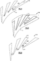
- Different variable geometry arrangements using vanes, which may be used in the refrigerant system 12, are shown in Figures 4-8 .
- an example variable geometry arrangement 148 includes circumferentially arranged vanes 72 disposed in the refrigerant outlet to provide circumferentially spaced passages 146.
- a throat 147 is provided in each of the passages 146 at the smallest area between adjacent vanes 72.
- An axially movable member 74 is arranged downstream from the impeller 18, and in the example, extend into the throat 147 a distance into the passage 146. The member 74 is moved by an actuator, in a manner similar to that described above with respect to member 48, to control the flow of refrigerant through the refrigerant outlet.
- variable geometry arrangement 248 is shown in Figure 5 .
- the axially movable member 174 surrounds each vane 172 such that the member 174 is provided along the entire passage 246 so the area of the passage 246 is varied along with the area of the throat 247.
- variable geometry arrangement 348 includes circumferentially spaced passages 346.
- the axially movable member 274 is arranged at the throat 347, but does not wrap about the leading edges of the vanes 272 as do the members 74, 174 illustrated in Figures 4 and 5 .
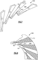
- Figure 7 illustrates a variable geometry arrangement 448 depicting vanes 372 that are rotatable between multiple positions (two shown in Figure 7 ) about pivots 78, which provide axes of rotation normal to the diffuser side walls. Rotation of the vanes 372 adjusts the throat 447 and flow of refrigerant into the passages 446.
- FIG. 8 Another example variable geometry arrangement 548 is shown in Figure 8 .
- the vanes 472 include leading edges 82 mounted on a rotatable ring 80 that are movable relative to the rest of the vanes 472 to regulate refrigerant flow through the passages 546.
- the circumferentially rotatable ring 80 is supported by the housing and is axially aligned with at least a portion of the impeller and arranged radially outward of the outlet end of the impeller.
- the leading edge of the vane does not provide the throat 547 in all vane positions.
Applications Claiming Priority (1)
| Application Number | Priority Date | Filing Date | Title |
|---|---|---|---|
| PCT/US2010/061754 WO2012087306A1 (en) | 2010-12-22 | 2010-12-22 | Variable-speed oil-free refrigerant centrifugal compressor with variable geometry diffuser |
Publications (3)
| Publication Number | Publication Date |
|---|---|
| EP2655890A1 EP2655890A1 (en) | 2013-10-30 |
| EP2655890A4 EP2655890A4 (en) | 2015-05-27 |
| EP2655890B1 true EP2655890B1 (en) | 2019-01-23 |
Family
ID=46314284
Family Applications (1)
| Application Number | Title | Priority Date | Filing Date |
|---|---|---|---|
| EP10860902.5A Not-in-force EP2655890B1 (en) | 2010-12-22 | 2010-12-22 | Variable-speed oil-free refrigerant centrifugal compressor with variable geometry diffuser |
Country Status (5)
| Country | Link |
|---|---|
| US (1) | US9212667B2 (zh) |
| EP (1) | EP2655890B1 (zh) |
| CN (1) | CN103261701B (zh) |
| AU (1) | AU2010365829A1 (zh) |
| WO (1) | WO2012087306A1 (zh) |
Families Citing this family (16)
| Publication number | Priority date | Publication date | Assignee | Title |
|---|---|---|---|---|
| WO2014182305A1 (en) * | 2013-05-09 | 2014-11-13 | Danfoss A/S | Compressor including impeller with radial flow inlet |
| US10330105B2 (en) | 2013-08-27 | 2019-06-25 | Danfoss A/S | Compressor including flow control insert and electromagnetic actuator |
| CN104632646A (zh) * | 2014-03-12 | 2015-05-20 | 珠海格力电器股份有限公司 | 离心式压缩机及具有其的离心机组 |
| US10458429B2 (en) | 2016-05-26 | 2019-10-29 | Rolls-Royce Corporation | Impeller shroud with slidable coupling for clearance control in a centrifugal compressor |
| US10774635B2 (en) | 2016-06-10 | 2020-09-15 | Halliburton Energy Services, Inc. | Restimulation process using coiled tubing and fiber optics |
| CN106091188A (zh) * | 2016-06-12 | 2016-11-09 | 重庆美的通用制冷设备有限公司 | 制冷机组 |
| US11293438B2 (en) | 2016-12-15 | 2022-04-05 | Carrier Corporation | Screw compressor with magnetic gear |
| TWI703267B (zh) | 2017-03-24 | 2020-09-01 | 美商江森自控技術公司 | 冷卻器組件的感應馬達及其蒸氣壓縮系統 |
| WO2019075088A1 (en) * | 2017-10-10 | 2019-04-18 | Johnson Controls Technology Company | SYSTEMS FOR AN ELECTRIC COOLER ENCLOSURE |
| CN110360130B (zh) | 2018-04-09 | 2022-12-27 | 开利公司 | 可变扩压器驱动系统 |
| EP4031774A4 (en) * | 2019-09-18 | 2023-10-11 | Massachusetts Institute of Technology | ADAPTIVE VOLUTES FOR CENTRIFUGAL PUMPS |
| KR20220140862A (ko) * | 2020-02-27 | 2022-10-18 | 존슨 컨트롤즈 타이코 아이피 홀딩스 엘엘피 | 체크 밸브로서의 가변 형상 디퓨저의 동작을 위한 시스템 및 방법 |
| US11668316B1 (en) * | 2022-01-07 | 2023-06-06 | Hamilton Sundstrand Corporation | Rotor formed of multiple metals |
| US11885352B1 (en) | 2022-09-12 | 2024-01-30 | Hamilton Sundstrand Corporation | Variable channel diffuser with moving floor |
| US11873839B1 (en) | 2022-09-12 | 2024-01-16 | Hamilton Sundstrand Corporation | Variable vaneless diffuser with moving floor |
| US11773870B1 (en) * | 2022-09-12 | 2023-10-03 | Hamilton Sundstrand Corporation | Variable channel diffuser |
Citations (3)
| Publication number | Priority date | Publication date | Assignee | Title |
|---|---|---|---|---|
| FR1429796A (fr) * | 1964-05-11 | 1966-02-25 | Sulzer Ag | Turbomachine |
| US4718819A (en) * | 1983-02-25 | 1988-01-12 | Teledyne Industries, Inc. | Variable geometry device for turbine compressor outlet |
| US20020184905A1 (en) * | 1999-12-06 | 2002-12-12 | Benedict Scott M. | Apparatus and method for controlling a magnetic bearing centrifugal chiller |
Family Cites Families (11)
| Publication number | Priority date | Publication date | Assignee | Title |
|---|---|---|---|---|
| US3478955A (en) * | 1968-03-11 | 1969-11-18 | Dresser Ind | Variable area diffuser for compressor |
| US4378194A (en) * | 1980-10-02 | 1983-03-29 | Carrier Corporation | Centrifugal compressor |
| US5807071A (en) | 1996-06-07 | 1998-09-15 | Brasz; Joost J. | Variable pipe diffuser for centrifugal compressor |
| US5669756A (en) | 1996-06-07 | 1997-09-23 | Carrier Corporation | Recirculating diffuser |
| US5924847A (en) * | 1997-08-11 | 1999-07-20 | Mainstream Engineering Corp. | Magnetic bearing centrifugal refrigeration compressor and refrigerant having minimum specific enthalpy rise |
| US6547520B2 (en) * | 2001-05-24 | 2003-04-15 | Carrier Corporation | Rotating vane diffuser for a centrifugal compressor |
| US6872050B2 (en) * | 2002-12-06 | 2005-03-29 | York International Corporation | Variable geometry diffuser mechanism |
| US7356999B2 (en) * | 2003-10-10 | 2008-04-15 | York International Corporation | System and method for stability control in a centrifugal compressor |
| US8567207B2 (en) * | 2007-10-31 | 2013-10-29 | Johnson Controls & Technology Company | Compressor control system using a variable geometry diffuser |
| US8069932B2 (en) | 2007-11-29 | 2011-12-06 | Schlumberger Technology Corporation | Method and apparatus for determining formation pararmeters using a seismic tool array |
| CN101896773B (zh) * | 2007-12-14 | 2013-06-19 | 开利公司 | 用于具有入口和出口流量控制装置的hvac系统的控制装置 |
-
2010
- 2010-12-22 EP EP10860902.5A patent/EP2655890B1/en not_active Not-in-force
- 2010-12-22 US US13/699,114 patent/US9212667B2/en not_active Expired - Fee Related
- 2010-12-22 CN CN201080070433.4A patent/CN103261701B/zh not_active Expired - Fee Related
- 2010-12-22 WO PCT/US2010/061754 patent/WO2012087306A1/en active Application Filing
- 2010-12-22 AU AU2010365829A patent/AU2010365829A1/en not_active Abandoned
Patent Citations (3)
| Publication number | Priority date | Publication date | Assignee | Title |
|---|---|---|---|---|
| FR1429796A (fr) * | 1964-05-11 | 1966-02-25 | Sulzer Ag | Turbomachine |
| US4718819A (en) * | 1983-02-25 | 1988-01-12 | Teledyne Industries, Inc. | Variable geometry device for turbine compressor outlet |
| US20020184905A1 (en) * | 1999-12-06 | 2002-12-12 | Benedict Scott M. | Apparatus and method for controlling a magnetic bearing centrifugal chiller |
Also Published As
| Publication number | Publication date |
|---|---|
| EP2655890A4 (en) | 2015-05-27 |
| WO2012087306A1 (en) | 2012-06-28 |
| US20130064682A1 (en) | 2013-03-14 |
| US9212667B2 (en) | 2015-12-15 |
| AU2010365829A1 (en) | 2013-05-23 |
| EP2655890A1 (en) | 2013-10-30 |
| CN103261701B (zh) | 2016-03-16 |
| CN103261701A (zh) | 2013-08-21 |
Similar Documents
| Publication | Publication Date | Title |
|---|---|---|
| EP2655890B1 (en) | Variable-speed oil-free refrigerant centrifugal compressor with variable geometry diffuser | |
| EP2807430B1 (en) | Variable-speed multi-stage refrigerant centrifugal compressor with diffusers | |
| US9810228B2 (en) | Centrifugal compressor diffuser control | |
| JP2975008B2 (ja) | 自由ロータ | |
| US10197064B2 (en) | Centrifugal compressor with fluid injector diffuser | |
| AU2013376868B2 (en) | Centrifugal compressor with extended operating range | |
| US20170260987A1 (en) | Centrifugal compressor with casing treatment bypass | |
| AU2012372806B2 (en) | High pressure ratio multi-stage centrifugal compressor | |
| EP3356681B1 (en) | Centrifugal compressor with flow regulation and surge prevention by axially shifting the impeller | |
| WO2013015885A1 (en) | Compressor surge detection | |
| CN111373155B (zh) | 紧凑可变几何形状的扩散器机构 | |
| US10557473B2 (en) | Control system and method for centrifugal compressor | |
| CN117345594A (zh) | 压缩机及包括压缩机的系统 |
Legal Events
| Date | Code | Title | Description |
|---|---|---|---|
| PUAI | Public reference made under article 153(3) epc to a published international application that has entered the european phase |
Free format text: ORIGINAL CODE: 0009012 |
|
| 17P | Request for examination filed |
Effective date: 20130515 |
|
| AK | Designated contracting states |
Kind code of ref document: A1 Designated state(s): AL AT BE BG CH CY CZ DE DK EE ES FI FR GB GR HR HU IE IS IT LI LT LU LV MC MK MT NL NO PL PT RO RS SE SI SK SM TR |
|
| DAX | Request for extension of the european patent (deleted) | ||
| RAP1 | Party data changed (applicant data changed or rights of an application transferred) |
Owner name: DANFOSS A/S |
|
| RA4 | Supplementary search report drawn up and despatched (corrected) |
Effective date: 20150429 |
|
| RIC1 | Information provided on ipc code assigned before grant |
Ipc: F04D 29/44 20060101AFI20150422BHEP |
|
| STAA | Information on the status of an ep patent application or granted ep patent |
Free format text: STATUS: EXAMINATION IS IN PROGRESS |
|
| 17Q | First examination report despatched |
Effective date: 20161107 |
|
| GRAP | Despatch of communication of intention to grant a patent |
Free format text: ORIGINAL CODE: EPIDOSNIGR1 |
|
| STAA | Information on the status of an ep patent application or granted ep patent |
Free format text: STATUS: GRANT OF PATENT IS INTENDED |
|
| INTG | Intention to grant announced |
Effective date: 20181012 |
|
| GRAS | Grant fee paid |
Free format text: ORIGINAL CODE: EPIDOSNIGR3 |
|
| GRAA | (expected) grant |
Free format text: ORIGINAL CODE: 0009210 |
|
| STAA | Information on the status of an ep patent application or granted ep patent |
Free format text: STATUS: THE PATENT HAS BEEN GRANTED |
|
| AK | Designated contracting states |
Kind code of ref document: B1 Designated state(s): AL AT BE BG CH CY CZ DE DK EE ES FI FR GB GR HR HU IE IS IT LI LT LU LV MC MK MT NL NO PL PT RO RS SE SI SK SM TR |
|
| REG | Reference to a national code |
Ref country code: GB Ref legal event code: FG4D |
|
| REG | Reference to a national code |
Ref country code: CH Ref legal event code: EP |
|
| REG | Reference to a national code |
Ref country code: AT Ref legal event code: REF Ref document number: 1091678 Country of ref document: AT Kind code of ref document: T Effective date: 20190215 |
|
| REG | Reference to a national code |
Ref country code: IE Ref legal event code: FG4D |
|
| REG | Reference to a national code |
Ref country code: DE Ref legal event code: R096 Ref document number: 602010056815 Country of ref document: DE |
|
| REG | Reference to a national code |
Ref country code: NL Ref legal event code: MP Effective date: 20190123 |
|
| PG25 | Lapsed in a contracting state [announced via postgrant information from national office to epo] |
Ref country code: NL Free format text: LAPSE BECAUSE OF FAILURE TO SUBMIT A TRANSLATION OF THE DESCRIPTION OR TO PAY THE FEE WITHIN THE PRESCRIBED TIME-LIMIT Effective date: 20190123 |
|
| PG25 | Lapsed in a contracting state [announced via postgrant information from national office to epo] |
Ref country code: LT Free format text: LAPSE BECAUSE OF FAILURE TO SUBMIT A TRANSLATION OF THE DESCRIPTION OR TO PAY THE FEE WITHIN THE PRESCRIBED TIME-LIMIT Effective date: 20190123 Ref country code: SE Free format text: LAPSE BECAUSE OF FAILURE TO SUBMIT A TRANSLATION OF THE DESCRIPTION OR TO PAY THE FEE WITHIN THE PRESCRIBED TIME-LIMIT Effective date: 20190123 Ref country code: ES Free format text: LAPSE BECAUSE OF FAILURE TO SUBMIT A TRANSLATION OF THE DESCRIPTION OR TO PAY THE FEE WITHIN THE PRESCRIBED TIME-LIMIT Effective date: 20190123 Ref country code: NO Free format text: LAPSE BECAUSE OF FAILURE TO SUBMIT A TRANSLATION OF THE DESCRIPTION OR TO PAY THE FEE WITHIN THE PRESCRIBED TIME-LIMIT Effective date: 20190423 Ref country code: PL Free format text: LAPSE BECAUSE OF FAILURE TO SUBMIT A TRANSLATION OF THE DESCRIPTION OR TO PAY THE FEE WITHIN THE PRESCRIBED TIME-LIMIT Effective date: 20190123 Ref country code: PT Free format text: LAPSE BECAUSE OF FAILURE TO SUBMIT A TRANSLATION OF THE DESCRIPTION OR TO PAY THE FEE WITHIN THE PRESCRIBED TIME-LIMIT Effective date: 20190523 Ref country code: FI Free format text: LAPSE BECAUSE OF FAILURE TO SUBMIT A TRANSLATION OF THE DESCRIPTION OR TO PAY THE FEE WITHIN THE PRESCRIBED TIME-LIMIT Effective date: 20190123 |
|
| REG | Reference to a national code |
Ref country code: AT Ref legal event code: MK05 Ref document number: 1091678 Country of ref document: AT Kind code of ref document: T Effective date: 20190123 |
|
| PG25 | Lapsed in a contracting state [announced via postgrant information from national office to epo] |
Ref country code: IS Free format text: LAPSE BECAUSE OF FAILURE TO SUBMIT A TRANSLATION OF THE DESCRIPTION OR TO PAY THE FEE WITHIN THE PRESCRIBED TIME-LIMIT Effective date: 20190523 Ref country code: BG Free format text: LAPSE BECAUSE OF FAILURE TO SUBMIT A TRANSLATION OF THE DESCRIPTION OR TO PAY THE FEE WITHIN THE PRESCRIBED TIME-LIMIT Effective date: 20190423 Ref country code: RS Free format text: LAPSE BECAUSE OF FAILURE TO SUBMIT A TRANSLATION OF THE DESCRIPTION OR TO PAY THE FEE WITHIN THE PRESCRIBED TIME-LIMIT Effective date: 20190123 Ref country code: LV Free format text: LAPSE BECAUSE OF FAILURE TO SUBMIT A TRANSLATION OF THE DESCRIPTION OR TO PAY THE FEE WITHIN THE PRESCRIBED TIME-LIMIT Effective date: 20190123 Ref country code: GR Free format text: LAPSE BECAUSE OF FAILURE TO SUBMIT A TRANSLATION OF THE DESCRIPTION OR TO PAY THE FEE WITHIN THE PRESCRIBED TIME-LIMIT Effective date: 20190424 Ref country code: HR Free format text: LAPSE BECAUSE OF FAILURE TO SUBMIT A TRANSLATION OF THE DESCRIPTION OR TO PAY THE FEE WITHIN THE PRESCRIBED TIME-LIMIT Effective date: 20190123 |
|
| REG | Reference to a national code |
Ref country code: DE Ref legal event code: R097 Ref document number: 602010056815 Country of ref document: DE |
|
| PG25 | Lapsed in a contracting state [announced via postgrant information from national office to epo] |
Ref country code: AL Free format text: LAPSE BECAUSE OF FAILURE TO SUBMIT A TRANSLATION OF THE DESCRIPTION OR TO PAY THE FEE WITHIN THE PRESCRIBED TIME-LIMIT Effective date: 20190123 Ref country code: DK Free format text: LAPSE BECAUSE OF FAILURE TO SUBMIT A TRANSLATION OF THE DESCRIPTION OR TO PAY THE FEE WITHIN THE PRESCRIBED TIME-LIMIT Effective date: 20190123 Ref country code: SK Free format text: LAPSE BECAUSE OF FAILURE TO SUBMIT A TRANSLATION OF THE DESCRIPTION OR TO PAY THE FEE WITHIN THE PRESCRIBED TIME-LIMIT Effective date: 20190123 Ref country code: EE Free format text: LAPSE BECAUSE OF FAILURE TO SUBMIT A TRANSLATION OF THE DESCRIPTION OR TO PAY THE FEE WITHIN THE PRESCRIBED TIME-LIMIT Effective date: 20190123 Ref country code: IT Free format text: LAPSE BECAUSE OF FAILURE TO SUBMIT A TRANSLATION OF THE DESCRIPTION OR TO PAY THE FEE WITHIN THE PRESCRIBED TIME-LIMIT Effective date: 20190123 Ref country code: CZ Free format text: LAPSE BECAUSE OF FAILURE TO SUBMIT A TRANSLATION OF THE DESCRIPTION OR TO PAY THE FEE WITHIN THE PRESCRIBED TIME-LIMIT Effective date: 20190123 Ref country code: RO Free format text: LAPSE BECAUSE OF FAILURE TO SUBMIT A TRANSLATION OF THE DESCRIPTION OR TO PAY THE FEE WITHIN THE PRESCRIBED TIME-LIMIT Effective date: 20190123 |
|
| PG25 | Lapsed in a contracting state [announced via postgrant information from national office to epo] |
Ref country code: SM Free format text: LAPSE BECAUSE OF FAILURE TO SUBMIT A TRANSLATION OF THE DESCRIPTION OR TO PAY THE FEE WITHIN THE PRESCRIBED TIME-LIMIT Effective date: 20190123 |
|
| PLBE | No opposition filed within time limit |
Free format text: ORIGINAL CODE: 0009261 |
|
| STAA | Information on the status of an ep patent application or granted ep patent |
Free format text: STATUS: NO OPPOSITION FILED WITHIN TIME LIMIT |
|
| PG25 | Lapsed in a contracting state [announced via postgrant information from national office to epo] |
Ref country code: AT Free format text: LAPSE BECAUSE OF FAILURE TO SUBMIT A TRANSLATION OF THE DESCRIPTION OR TO PAY THE FEE WITHIN THE PRESCRIBED TIME-LIMIT Effective date: 20190123 |
|
| 26N | No opposition filed |
Effective date: 20191024 |
|
| PG25 | Lapsed in a contracting state [announced via postgrant information from national office to epo] |
Ref country code: SI Free format text: LAPSE BECAUSE OF FAILURE TO SUBMIT A TRANSLATION OF THE DESCRIPTION OR TO PAY THE FEE WITHIN THE PRESCRIBED TIME-LIMIT Effective date: 20190123 |
|
| PG25 | Lapsed in a contracting state [announced via postgrant information from national office to epo] |
Ref country code: TR Free format text: LAPSE BECAUSE OF FAILURE TO SUBMIT A TRANSLATION OF THE DESCRIPTION OR TO PAY THE FEE WITHIN THE PRESCRIBED TIME-LIMIT Effective date: 20190123 |
|
| REG | Reference to a national code |
Ref country code: DE Ref legal event code: R119 Ref document number: 602010056815 Country of ref document: DE |
|
| REG | Reference to a national code |
Ref country code: CH Ref legal event code: PL |
|
| REG | Reference to a national code |
Ref country code: BE Ref legal event code: MM Effective date: 20191231 |
|
| PG25 | Lapsed in a contracting state [announced via postgrant information from national office to epo] |
Ref country code: MC Free format text: LAPSE BECAUSE OF FAILURE TO SUBMIT A TRANSLATION OF THE DESCRIPTION OR TO PAY THE FEE WITHIN THE PRESCRIBED TIME-LIMIT Effective date: 20190123 |
|
| GBPC | Gb: european patent ceased through non-payment of renewal fee |
Effective date: 20191222 |
|
| PG25 | Lapsed in a contracting state [announced via postgrant information from national office to epo] |
Ref country code: DE Free format text: LAPSE BECAUSE OF NON-PAYMENT OF DUE FEES Effective date: 20200701 Ref country code: FR Free format text: LAPSE BECAUSE OF NON-PAYMENT OF DUE FEES Effective date: 20191231 Ref country code: LU Free format text: LAPSE BECAUSE OF NON-PAYMENT OF DUE FEES Effective date: 20191222 Ref country code: IE Free format text: LAPSE BECAUSE OF NON-PAYMENT OF DUE FEES Effective date: 20191222 Ref country code: GB Free format text: LAPSE BECAUSE OF NON-PAYMENT OF DUE FEES Effective date: 20191222 |
|
| PG25 | Lapsed in a contracting state [announced via postgrant information from national office to epo] |
Ref country code: CH Free format text: LAPSE BECAUSE OF NON-PAYMENT OF DUE FEES Effective date: 20191231 Ref country code: LI Free format text: LAPSE BECAUSE OF NON-PAYMENT OF DUE FEES Effective date: 20191231 Ref country code: BE Free format text: LAPSE BECAUSE OF NON-PAYMENT OF DUE FEES Effective date: 20191231 |
|
| PG25 | Lapsed in a contracting state [announced via postgrant information from national office to epo] |
Ref country code: CY Free format text: LAPSE BECAUSE OF FAILURE TO SUBMIT A TRANSLATION OF THE DESCRIPTION OR TO PAY THE FEE WITHIN THE PRESCRIBED TIME-LIMIT Effective date: 20190123 |
|
| PG25 | Lapsed in a contracting state [announced via postgrant information from national office to epo] |
Ref country code: HU Free format text: LAPSE BECAUSE OF FAILURE TO SUBMIT A TRANSLATION OF THE DESCRIPTION OR TO PAY THE FEE WITHIN THE PRESCRIBED TIME-LIMIT; INVALID AB INITIO Effective date: 20101222 Ref country code: MT Free format text: LAPSE BECAUSE OF FAILURE TO SUBMIT A TRANSLATION OF THE DESCRIPTION OR TO PAY THE FEE WITHIN THE PRESCRIBED TIME-LIMIT Effective date: 20190123 |
|
| PG25 | Lapsed in a contracting state [announced via postgrant information from national office to epo] |
Ref country code: MK Free format text: LAPSE BECAUSE OF FAILURE TO SUBMIT A TRANSLATION OF THE DESCRIPTION OR TO PAY THE FEE WITHIN THE PRESCRIBED TIME-LIMIT Effective date: 20190123 |