EP2655880B1 - Windenergieanlage mit Getriebe/Generator Kupplung - Google Patents
Windenergieanlage mit Getriebe/Generator Kupplung Download PDFInfo
- Publication number
- EP2655880B1 EP2655880B1 EP11819066.9A EP11819066A EP2655880B1 EP 2655880 B1 EP2655880 B1 EP 2655880B1 EP 11819066 A EP11819066 A EP 11819066A EP 2655880 B1 EP2655880 B1 EP 2655880B1
- Authority
- EP
- European Patent Office
- Prior art keywords
- generator
- shaft
- coupling
- wind turbine
- transmission
- Prior art date
- Legal status (The legal status is an assumption and is not a legal conclusion. Google has not performed a legal analysis and makes no representation as to the accuracy of the status listed.)
- Active
Links
Images
Classifications
-
- F—MECHANICAL ENGINEERING; LIGHTING; HEATING; WEAPONS; BLASTING
- F03—MACHINES OR ENGINES FOR LIQUIDS; WIND, SPRING, OR WEIGHT MOTORS; PRODUCING MECHANICAL POWER OR A REACTIVE PROPULSIVE THRUST, NOT OTHERWISE PROVIDED FOR
- F03D—WIND MOTORS
- F03D15/00—Transmission of mechanical power
-
- F—MECHANICAL ENGINEERING; LIGHTING; HEATING; WEAPONS; BLASTING
- F03—MACHINES OR ENGINES FOR LIQUIDS; WIND, SPRING, OR WEIGHT MOTORS; PRODUCING MECHANICAL POWER OR A REACTIVE PROPULSIVE THRUST, NOT OTHERWISE PROVIDED FOR
- F03D—WIND MOTORS
- F03D7/00—Controlling wind motors
- F03D7/02—Controlling wind motors the wind motors having rotation axis substantially parallel to the air flow entering the rotor
- F03D7/0244—Controlling wind motors the wind motors having rotation axis substantially parallel to the air flow entering the rotor for braking
-
- F—MECHANICAL ENGINEERING; LIGHTING; HEATING; WEAPONS; BLASTING
- F03—MACHINES OR ENGINES FOR LIQUIDS; WIND, SPRING, OR WEIGHT MOTORS; PRODUCING MECHANICAL POWER OR A REACTIVE PROPULSIVE THRUST, NOT OTHERWISE PROVIDED FOR
- F03D—WIND MOTORS
- F03D15/00—Transmission of mechanical power
- F03D15/20—Gearless transmission, i.e. direct-drive
-
- F—MECHANICAL ENGINEERING; LIGHTING; HEATING; WEAPONS; BLASTING
- F03—MACHINES OR ENGINES FOR LIQUIDS; WIND, SPRING, OR WEIGHT MOTORS; PRODUCING MECHANICAL POWER OR A REACTIVE PROPULSIVE THRUST, NOT OTHERWISE PROVIDED FOR
- F03D—WIND MOTORS
- F03D17/00—Monitoring or testing of wind motors, e.g. diagnostics
-
- F—MECHANICAL ENGINEERING; LIGHTING; HEATING; WEAPONS; BLASTING
- F03—MACHINES OR ENGINES FOR LIQUIDS; WIND, SPRING, OR WEIGHT MOTORS; PRODUCING MECHANICAL POWER OR A REACTIVE PROPULSIVE THRUST, NOT OTHERWISE PROVIDED FOR
- F03D—WIND MOTORS
- F03D80/00—Details, components or accessories not provided for in groups F03D1/00 - F03D17/00
- F03D80/70—Bearing or lubricating arrangements
-
- F—MECHANICAL ENGINEERING; LIGHTING; HEATING; WEAPONS; BLASTING
- F16—ENGINEERING ELEMENTS AND UNITS; GENERAL MEASURES FOR PRODUCING AND MAINTAINING EFFECTIVE FUNCTIONING OF MACHINES OR INSTALLATIONS; THERMAL INSULATION IN GENERAL
- F16D—COUPLINGS FOR TRANSMITTING ROTATION; CLUTCHES; BRAKES
- F16D7/00—Slip couplings, e.g. slipping on overload, for absorbing shock
- F16D7/02—Slip couplings, e.g. slipping on overload, for absorbing shock of the friction type
-
- F—MECHANICAL ENGINEERING; LIGHTING; HEATING; WEAPONS; BLASTING
- F05—INDEXING SCHEMES RELATING TO ENGINES OR PUMPS IN VARIOUS SUBCLASSES OF CLASSES F01-F04
- F05B—INDEXING SCHEME RELATING TO WIND, SPRING, WEIGHT, INERTIA OR LIKE MOTORS, TO MACHINES OR ENGINES FOR LIQUIDS COVERED BY SUBCLASSES F03B, F03D AND F03G
- F05B2240/00—Components
- F05B2240/60—Shafts
- F05B2240/61—Shafts hollow
-
- F—MECHANICAL ENGINEERING; LIGHTING; HEATING; WEAPONS; BLASTING
- F05—INDEXING SCHEMES RELATING TO ENGINES OR PUMPS IN VARIOUS SUBCLASSES OF CLASSES F01-F04
- F05B—INDEXING SCHEME RELATING TO WIND, SPRING, WEIGHT, INERTIA OR LIKE MOTORS, TO MACHINES OR ENGINES FOR LIQUIDS COVERED BY SUBCLASSES F03B, F03D AND F03G
- F05B2260/00—Function
- F05B2260/40—Transmission of power
- F05B2260/402—Transmission of power through friction drives
- F05B2260/4023—Transmission of power through friction drives through a friction clutch
-
- F—MECHANICAL ENGINEERING; LIGHTING; HEATING; WEAPONS; BLASTING
- F16—ENGINEERING ELEMENTS AND UNITS; GENERAL MEASURES FOR PRODUCING AND MAINTAINING EFFECTIVE FUNCTIONING OF MACHINES OR INSTALLATIONS; THERMAL INSULATION IN GENERAL
- F16H—GEARING
- F16H1/00—Toothed gearings for conveying rotary motion
- F16H1/28—Toothed gearings for conveying rotary motion with gears having orbital motion
-
- Y—GENERAL TAGGING OF NEW TECHNOLOGICAL DEVELOPMENTS; GENERAL TAGGING OF CROSS-SECTIONAL TECHNOLOGIES SPANNING OVER SEVERAL SECTIONS OF THE IPC; TECHNICAL SUBJECTS COVERED BY FORMER USPC CROSS-REFERENCE ART COLLECTIONS [XRACs] AND DIGESTS
- Y02—TECHNOLOGIES OR APPLICATIONS FOR MITIGATION OR ADAPTATION AGAINST CLIMATE CHANGE
- Y02E—REDUCTION OF GREENHOUSE GAS [GHG] EMISSIONS, RELATED TO ENERGY GENERATION, TRANSMISSION OR DISTRIBUTION
- Y02E10/00—Energy generation through renewable energy sources
- Y02E10/70—Wind energy
- Y02E10/72—Wind turbines with rotation axis in wind direction
Definitions
- the invention relates to a suitable for use in wind turbines coupling for connecting the output of a transmission to the drive of a generator.
- Such a coupling is known, for example, from the company KTR Kupplungstechnik GmbH, which is traded under the sign RADEX ® -N and which connects the gear shaft with the generator shaft by means of an intermediate piece made of glass fiber reinforced plastic.
- This clutch additionally has a sensor disk for speed monitoring, a torque limiter designed as a slip hub for protecting the transmission from generator-side load peaks and a transmission-side brake disk.
- the installation of the clutch in particular the alignment of the gear and generator or gear shaft and generator shaft to each other is very labor intensive and error prone, with a misalignment of gear shaft to generator shaft can lead to increased bearing load in the gearbox and generator.
- the gear shaft and the generator shaft are very easily connected by means of clamping sets with the clutch, but the distance between the gear and generator or gear shaft and generator shaft, especially the alignment of the axes at a standstill and under load, each be adjusted so that an optimal Connection of the clutch with gear shaft and generator shaft can be achieved.
- EP 0 811 764 A1 discloses a wind turbine with a coupling between the transmission and generator of the prior art.
- Object of the present invention is therefore to provide a wind turbine with a coupling for connecting the output of a transmission to the drive of a generator, so for connecting transmission shaft with generator shaft, the less can be laboriously set up and has a compact design compared to the prior art.
- the basic idea of the invention is not to arrange the coupling spatially between the gearbox and the generator, but to connect the gearbox shaft and the generator shaft to one another on the side of the generator facing away from the gearbox. As a result, transmission and generator can be arranged very close to each other and the wind turbine can be built very compact.
- the machine train in the inventive arrangement linear i. from one side to the other side, preferably from the side of the rotor bearing to the side of the generator, can be constructed without a change in the relative position of the components must be made to each other. Due to the concentric design, the alignment of the components results automatically, without complex adaptation processes are necessary.
- the arrangement according to the invention is also particularly simple, because it can be dispensed with a separate storage of the transmission output shaft, since it is mounted on the clutch through the generator bearing.
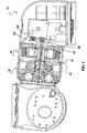
- Fig. 1 shows a section through a SCD ® -Windenergy plant in the area designed as a head carrier nacelle.
- the wind energy plant shown as a preferred embodiment essentially shows that from the WO 2008/113318 A2 known structure, so that reference is made to the pre-published document for not directly belonging to the present invention components.
- the present invention is not limited to use in the prior art wind turbine, but can be used in any wind turbine - it is particularly advantageous only in the SCD wind turbine shown due to the small footprint and the other advantages mentioned above.
- the wind power plant 10 which is preferably configured, has a two-stage planetary gear 20 with a gearshaft 30 acting as a gearbox output, and a generator 40 with a generator shaft 50 acting as a generator drive.
- the clutch 60 for connecting the transmission output shaft 30 to the generator drive shaft 50 is disposed on the side of the generator 40 opposite to the transmission 20.
- the generator shaft 50 is designed as a hollow shaft, so that the transmission shaft 30 through the generator shaft 50 and thus by the generator 40 from the side facing the gear 20 to the side facing away from the transmission 20 Generator 40 can be performed.
- the clutch 60 can thus be connected on the side facing away from the transmission 20 of the generator 40 on the one hand readily with the gear shaft 50 and on the other hand with the generator shaft 50 piercing gear shaft 30, for example by means of a clamping set.
- the generator shaft 50 and the rotor of the generator 40 is considered, so that the coupling 60 may also be connected directly to the rotor of the generator 40.
- a separate storage of the transmission shaft 30 is not required in this embodiment, since the transmission shaft 30 is mounted by the connection with the clutch 60 together with the generator shaft 50 in the camp.
- a fixed hollow pin 70 is provided on the outside of two bearings for supporting the generator shaft 50 (or the rotor of the generator 40) are provided, whereas in the cavity of the pin 70, the output shaft 30 of the transmission 20 is guided.
- the generator shaft 50 may also be mounted in the pin 70, when the pin 70 is formed as part of the housing.
- the transmission shaft 30 may be formed as a hollow shaft to receive, for example, from the rear region of the head carrier in the hub of the wind turbine 10 leading supply lines.
- the clutch 60 is designed to protect the transmission 40 from briefly occurring high moments, for example in the case of a generator short circuit, as a slip clutch.
- the slip clutch 60 has a sensor that slips through the clutch 60, for example a displacement sensor, so that the sensor detects a relative movement from the transmission shaft 30 to the generator shaft 50 that occurs on the slip clutch.
- the sensor not only detects slippage, but also the slip angle per slide.
- the wind energy plant 10 has a data processing device connected to the sensor, which logs the slippage and, if appropriate, forwards it to a central point for monitoring the wind power plant 10.
- a data processing device connected to the sensor, which logs the slippage and, if appropriate, forwards it to a central point for monitoring the wind power plant 10.
- the frequent occurrence of skidding movements on the clutch 60 within a certain period of time and / or particularly high slip angles per skid signal that the slip clutch 60 is readjusted and / or the system 10 must generally be serviced.
- stepped messages are conceivable, which can be marked with different colors, eg yellow or red, to give the operator of the wind turbine quickly overview of the most important messages and take the necessary measures for proper operation or this again to be able to produce.
- the operator or preferably the Data processing device itself the power of the wind turbine, preferably graded by 20%, reduce or even switch off to avoid too frequent slipping and thus wear until the next maintenance.
- the coupling part connected to the transmission shaft 30 has a brake disc 80 interacting with a disc brake 90, the sliding element of the coupling 60 being arranged between the coupling part connected to the transmission shaft 30 and the coupling part connected to the generator shaft 50.
- the disk brake while bypassing the slip clutch 60, acts directly on the transmission shaft 30 and the wind energy plant 10 is completely decelerated.
Landscapes
- Engineering & Computer Science (AREA)
- General Engineering & Computer Science (AREA)
- Mechanical Engineering (AREA)
- Life Sciences & Earth Sciences (AREA)
- Sustainable Development (AREA)
- Sustainable Energy (AREA)
- Chemical & Material Sciences (AREA)
- Combustion & Propulsion (AREA)
- Wind Motors (AREA)
Description
- Die Erfindung betrifft eine zur Verwendung bei Windenergieanlagen geeignete Kupplung zum Verbinden des Abtriebs eines Getriebes mit dem Antrieb eines Generators.
- Eine derartige Kupplung ist beispielsweise von der Firma KTR Kupplungstechnik GmbH bekannt, die unter dem Zeichen RADEX®-N gehandelt wird und die die Getriebewelle mit der Generatorwelle mittels eines aus glasfaserverstärktem Kunststoff hergestellten Zwischenstücks miteinander verbindet. Diese Kupplung weist zusätzlich eine Sensorscheibe zur Drehzahlüberwachung, eine als Rutschnabe ausgebildete Drehmomentbegrenzung zum Schutz des Getriebes vor generatorseitigen Lastspitzen und eine getriebeseitige Bremsscheibe auf.
- Diese Art Kupplung hat jedoch aufgrund der Anordnung des Zwischenstücks zwischen Getriebewelle und Generatorwelle einen relativ hohen Platzbedarf, der einer zunehmend gewünschten kompakten Bauweise einer Windenergieanlage entgegensteht.
- Darüber hinaus ist die Installation der Kupplung, insbesondere die Ausrichtung von Getriebe und Generator bzw. Getriebewelle und Generatorwelle zueinander sehr arbeitsaufwändig und fehlerträchtig, wobei eine Fehlausrichtung von Getriebewelle zu Generatorwelle zu einer erhöhten Lagerbelastung im Getriebe und Generator führen kann. Zwar werden die Getriebewelle und die Generatorwelle sehr einfach mittels Spannsätzen mit der Kupplung verbunden, dennoch muss der Abstand von Getriebe und Generator bzw. Getriebewelle und Generatorwelle, vor allem die Fluchtung der Achsen im Stillstand und unter Last, jeweils so justiert werden, dass eine optimale Verbindung der Kupplung mit Getriebewelle und Generatorwelle erreicht werden kann.
-
EP 0 811 764 A1 offenbart eine Windenergieanlage mit einer Kupplung zwischen Getrieb und Generator aus dem Stand der Technik. - Aufgabe der vorliegenden Erfindung ist es daher, eine Windenergieanlage mit einer Kupplung zum Verbinden des Abtriebs eines Getriebes mit dem Antrieb eines Generators, also zum Verbinden von Getriebewelle mit Generatorwelle bereitzustellen, die weniger arbeitsaufwändig eingerichtet werden kann und eine gegenüber dem Stand der Technik kompaktere Bauweise aufweist.
- Die Aufgabe wird durch die Anordnung mit den Merkmalen von Anspruch 1 gelöst. Die Unteransprüche geben vorteilhafte Ausgestaltungen der Erfindung wieder.
- Grundgedanke der Erfindung ist es, die Kupplung nicht räumlich zwischen Getriebe und Generator anzuordnen, sondern Getriebewelle und Generatorwelle auf der dem Getriebe abgewandten Seite des Generators miteinander zu verbinden. Dadurch können Getriebe und Generator sehr dicht zueinander angeordnet und die Windenergieanlage sehr kompakt gebaut werden.
- Dabei kann auch - wie aus dem Stand der Technik bekannt - eine Drehzahlüberwachung, eine Drehmomentbegrenzung und eine Bremsscheibe zum Bremsen der Getriebewelle realisiert werden. Diese konstruktiven Maßnahmen haben nur einen geringen Platzbedarf, wobei die Anordnung vom Rotor ausgesehen hinter dem Generator auch gut zugänglich und damit sehr servicefreundlich ist.
- Schließlich ist es von großem Vorteil, dass der Maschinenstrang bei der erfindungsgemäßen Anordnung linear, d.h. von einer Seite zur anderen Seite, bevorzugt von der Seite des Rotorlagers bis zur Seite des Generators, aufgebaut werden kann, ohne dass eine Änderung der relativen Position der Komponenten zueinander erfolgen muss. Aufgrund der konzentrischen Bauweise ergibt sich die Ausrichtung der Komponenten automatisch, ohne dass aufwändige Anpassungsprozesse notwendig sind.
- Schließlich ist die erfindungsgemäße Anordnung auch deshalb besonders einfach, weil auf eine gesonderte Lagerung der Getriebeabtriebswelle verzichtet werden kann, da diese über die Kupplung durch das Generatorlager gelagert wird.
- Die Erfindung wird anhand eines in der beigefügten Zeichnung dargestellten, besonders bevorzugt ausgestalteten Ausführungsbeispiels näher erläutert.
-
Fig. 1 zeigt einen Schnitt durch eine SCD®-Windenergieanlage im Bereich der als Kopfträger ausgebildeten Gondel. Die als bevorzugtes Ausführungsbeispiel dargestellte Windenergieanlage zeigt im Wesentlichen den aus derWO 2008/113318 A2 bekannten Aufbau, sodass für die nicht unmittelbar zur vorliegenden Erfindung gehörenden Komponenten auf die vorveröffentlichte Schrift verwiesen wird. Im Übrigen ist die vorliegende Erfindung nicht zur Verwendung auf die vorbekannte Windenergieanlage beschränkt, sondern kann in jeder Windenergieanlage verwendet werden - sie ist lediglich in der gezeigten SCD-Windenergieanlage aufgrund des nur geringen Platzbedarfs und der weiteren oben genannten Vorteile besonders vorteilhaft. - Die bevorzugt ausgestaltete Windenergieanlage 10 weist ein zweistufiges Planetengetriebe 20 mit einer als Getriebeabtrieb wirkenden Getriebewelle 30 und einen Generator 40 mit einer als Generatorantrieb wirkenden Generatorwelle 50 auf.
- Erfindungsgemäß ist die Kupplung 60 zum Verbinden der Getriebeabtriebswelle 30 mit der Generatorantriebswelle 50 auf der Seite des Generators 40 angeordnet, die dem Getriebe 20 gegenüberliegt. Um nun eine Verbindung zwischen Getriebewelle 30 und Generatorwelle 50 zu ermöglichen, ist die Generatorwelle 50 als Hohlwelle ausgeführt, sodass die Getriebewelle 30 durch die Generatorwelle 50 und damit durch den Generator 40 von der dem Getriebe 20 zugewandten Seite zu der dem Getriebe 20 abgewandten Seite des Generators 40 geführt werden kann.
- Die Kupplung 60 kann damit auf der dem Getriebe 20 abgewandten Seite des Generators 40 einerseits ohne weiteres mit der Getriebewelle 50 und andererseits mit der die Generatorwelle 50 durchstoßenden Getriebewelle 30 beispielsweise mittels eines Spannsatzes verbunden werden. Als Generatorwelle 50 wird auch der Rotor des Generators 40 angesehen, sodass die Kupplung 60 auch direkt mit dem Rotor des Generators 40 verbunden sein kann.
- Einer gesonderten Lagerung der Getriebewelle 30 bedarf es bei dieser Ausführung nicht, da die Getriebewelle 30 durch die Verbindung mit der Kupplung 60 gemeinsam mit der Generatorwelle 50 in deren Lager gelagert wird.
- Insbesondere ist ein feststehender hohler Zapfen 70 vorgesehen, auf dessen Außenseite zwei Lager zur Lagerung der Generatorwelle 50 (bzw. des Rotors des Generators 40) vorgesehen sind, wohingegen im Hohlraum des Zapfens 70 die Abtriebswelle 30 des Getriebes 20 geführt ist. Die Generatorwelle 50 kann aber auch ebenso im Zapfen 70 gelagert sein, wenn der Zapfen 70 als Teil des Gehäuses ausgebildet ist. Dabei kann auch die Getriebewelle 30 als Hohlwelle ausgebildet zu sein, um beispielsweise aus dem hinteren Bereich des Kopfträgers in die Nabe der Windenergieanlage 10 führende Versorgungsleitungen aufzunehmen.
- Weiterhin ist die Kupplung 60 zum Schutz des Getriebes 40 vor kurzzeitig auftretenden hohen Momenten, beispielsweise bei einem Generatorkurzschluss, als Rutschkupplung ausgebildet. Besonders bevorzugt weist die Rutschkupplung 60 einen ein Durchrutschen der Kupplung 60 erfassenden Sensor, beispielsweise einen Wegmesser, aufder Sensor erfasst also eine an der Rutschkupplung auftretende Relativbewegung von Getriebewelle 30 zu Generatorwelle 50. Höchst bevorzugt erfasst der Sensor nicht nur ein Durchrutschen, sondern auch den Rutschwinkel pro Rutschvorgang.
- Darüber hinaus verfügt die Windenergieanlage 10 über eine mit dem Sensor verbundene Datenverarbeitungseinrichtung, die das Durchrutschen protokolliert und gegebenenfalls an eine zentrale Stelle zur Überwachung der Windenergieanlage 10 weiterleitet. So können beispielsweise das häufige Auftreten von Rutschbewegungen an der Kupplung 60 innerhalb eines bestimmten Zeitraums und/oder besonders hohe Rutschwinkel pro Rutschvorgang signalisieren, dass die Rutschkupplung 60 nachjustiert werden und/oder die Anlage 10 generell gewartet werden muss. Dabei sind auch nach Dringlichkeit gestufte Meldungen denkbar, die mit unterschiedlichen Farben, z.B. gelb oder rot, markiert sein können, um dem Betreiber der Windenergieanlage schnell einen Überblick über die wichtigsten Meldungen zu verschaffen und die notwendigen Maßnahmen für den einwandfreien Betrieb ergreifen bzw. diesen wieder herstellen zu können. So kann beispielsweise der Betreiber oder bevorzugt die Datenverarbeitungseinrichtung selbst die Leistung der Windenergieanlage, vorzugsweise abgestuft um jeweils 20 %, reduzieren oder gar abschalten, um ein zu häufiges Durchrutschen und damit Verschleiß bis zur nächsten Wartung zu vermeiden.
- Schließlich weist der mit der Getriebewelle 30 verbundene Kupplungsteil eine mit einer Scheibenbremse 90 zusammenwirkende Bremsscheibe 80 auf, wobei das Rutschelement der Kupplung 60 zwischen dem mit der Getriebewelle 30 verbundenen Kupplungsteil und dem mit der Generatorwelle 50 verbundenen Kupplungsteil angeordnet ist. Dadurch kann die Scheibenbremse unter Umgehung der Rutschkupplung 60 direkt auf die Getriebewelle 30 wirken und die Windenergieanlage 10 vollständig abgebremst werden.
Claims (7)
- Windenergieanlage (10) mit- einem Getriebe (20),- einer als Getriebeabtrieb wirkenden Getriebewelle (30),- einem Generator (40),- einer als Generatorantrieb wirkenden Generatorwelle (50),- einer die Getriebewelle (30) und die Generatorwelle (50) miteinander verbindenden Kupplung (60),wobei- die Generatorwelle (50) als Hohlwelle ausgebildet ist,- die Kupplung (60) auf der dem Getriebe (20) abgewandten Seite des Generators (40) mit der Generatorwelle (50) verbunden angeordnet und als Rutschkupplung ausgebildet ist, und- die Getriebewelle (30) die Generatorwelle (50) durchstoßend mit der Kupplung (60) verbunden istdadurch gekennzeichnet, dass
der mit der Getriebewelle (30) verbundene Kupplungsteil eine mit einer Scheibenbremse (90) zusammenwirkende Bremsscheibe (80) aufweist, wobei das Rutschelement der Kupplung (60) zwischen dem mit der Getriebewelle (30) verbundenen Kupplungsteil und dem mit der Generatorwelle (50) verbundenen Kupplungsteil angeordnet ist. - Windenergieanlage (10) nach Anspruch 1, dadurch gekennzeichnet, dass die Generatorwelle (50) an einem im Inneren der Generatorwelle (50) konzentrisch angeordneten Zapfen (70) gelagert ist, wobei der Zapfen (70) hohl ausgebildet und die Getriebewelle (30) durch den Hohlraum des Zapfen (70) durchgeführt ist.
- Windenergieanlage (10) nach einem der vorhergehenden Ansprüche, dadurch gekennzeichnet, dass die Getriebewelle (30) durch die Verbindung der Getriebewelle (30) mit der Generatorwelle (50) mittels der Kupplung (60) in der Generatorwellenlagerung gelagert ist.
- Windenergieanlage (10) nach einem der vorhergehenden Ansprüche, gekennzeichnet durch einen ein Durchrutschen der Kupplung (60) erfassenden Sensor.
- Windenergieanlage (10) nach einem der vorhergehenden Ansprüche, gekennzeichnet durch einen Sensor zum Erfassen des Rutschwinkels pro Rutschvorgang.
- Windenergieanlage (10) nach einem der Ansprüche 4 und 5, gekennzeichnet durch eine mit dem Sensor verbundene Datenverarbeitungseinrichtung zur Ausgabe eines Warnsignals bei Überschreiten einer vorbestimmten erfassten Rutschanzahl und/oder eines vorbestimmten erfassten Rutschwinkels.
- Windenergieanlage (10) nach Anspruch 6, dadurch gekennzeichnet, dass die Datenverarbeitungseinrichtung eine Leistungsreduzierung oder eine Abschaltung der Anlage auslöst.
Applications Claiming Priority (2)
| Application Number | Priority Date | Filing Date | Title |
|---|---|---|---|
| DE102010055876A DE102010055876A1 (de) | 2010-12-24 | 2010-12-24 | Getriebe/Generator-Kupplung |
| PCT/DE2011/002166 WO2012083931A1 (de) | 2010-12-24 | 2011-12-22 | Getriebe/generator-kupplung |
Publications (2)
| Publication Number | Publication Date |
|---|---|
| EP2655880A1 EP2655880A1 (de) | 2013-10-30 |
| EP2655880B1 true EP2655880B1 (de) | 2014-04-23 |
Family
ID=45688342
Family Applications (1)
| Application Number | Title | Priority Date | Filing Date |
|---|---|---|---|
| EP11819066.9A Active EP2655880B1 (de) | 2010-12-24 | 2011-12-22 | Windenergieanlage mit Getriebe/Generator Kupplung |
Country Status (6)
| Country | Link |
|---|---|
| US (1) | US9863399B2 (de) |
| EP (1) | EP2655880B1 (de) |
| CN (1) | CN103210214B (de) |
| DE (1) | DE102010055876A1 (de) |
| DK (1) | DK2655880T3 (de) |
| WO (1) | WO2012083931A1 (de) |
Families Citing this family (4)
| Publication number | Priority date | Publication date | Assignee | Title |
|---|---|---|---|---|
| US9440800B1 (en) * | 2015-08-19 | 2016-09-13 | Joy Mm Delaware, Inc. | Conveyor slip detection and control |
| ES2656821B1 (es) * | 2016-08-30 | 2018-12-04 | Siemens Gamesa Renewable Energy Innovation & Technology, S.L. | Generador síncrono para aerogeneradores |
| DE102019119473A1 (de) * | 2019-07-18 | 2021-01-21 | Renk Aktiengesellschaft | Triebstranganordnung |
| US11774324B2 (en) * | 2021-03-12 | 2023-10-03 | General Electric Renovables Espana, S.L. | System and method for detecting actual slip in a coupling of a rotary shaft |
Family Cites Families (13)
| Publication number | Priority date | Publication date | Assignee | Title |
|---|---|---|---|---|
| DE29609794U1 (de) * | 1996-06-03 | 1996-08-22 | aerodyn GmbH, 24768 Rendsburg | Getriebe-Generator-Kombination |
| DE102007012408A1 (de) | 2007-03-15 | 2008-09-18 | Aerodyn Engineering Gmbh | Windenergieanlagen mit lastübertragenden Bauteilen |
| DE102007019513B4 (de) * | 2007-04-25 | 2012-03-15 | Aerodyn Engineering Gmbh | Windenergieanlage |
| US7948100B2 (en) * | 2007-12-19 | 2011-05-24 | General Electric Company | Braking and positioning system for a wind turbine rotor |
| US7944067B2 (en) * | 2008-04-01 | 2011-05-17 | General Electric Company | System and method for reducing rotor loads in a wind turbine upon detection of blade-pitch failure and loss of counter-torque |
| FI20080510A7 (fi) * | 2008-09-10 | 2010-03-11 | Mervento Oy | Tuulivoimala |
| JP5010619B2 (ja) * | 2009-01-06 | 2012-08-29 | 三菱重工業株式会社 | 風力発電装置および風力発電装置の制御方法 |
| US7815536B2 (en) * | 2009-01-16 | 2010-10-19 | General Electric Company | Compact geared drive train |
| EP2251543B1 (de) * | 2009-05-14 | 2016-12-07 | ALSTOM Renewable Technologies | Verfahren und System zur Vorhersage des Vorkommens einer Windböe an einer Windturbine |
| AT508155B1 (de) * | 2009-05-25 | 2010-11-15 | Hehenberger Gerald Dipl Ing | Energiegewinnungsanlage, insbesondere windkraftanlage |
| EP2354539B1 (de) * | 2010-01-14 | 2012-05-23 | Nordex Energy GmbH | Windenergieanlage mit einem Azimutsystem sowie Verfahren zur Azimutverstellung einer Windenergieanlage |
| DE202010012659U1 (de) | 2010-09-16 | 2010-12-09 | Ktr Kupplungstechnik Gmbh | Überlastkupplung mit einer Vorrichtung zur Ermittlung ihres Rutschwinkels |
| DE202010012752U1 (de) | 2010-09-20 | 2010-12-02 | Centa-Antriebe Kirschey Gmbh | Vorrichtung zur kraftübertragenden Verbindung zweier Aggregate |
-
2010
- 2010-12-24 DE DE102010055876A patent/DE102010055876A1/de not_active Withdrawn
-
2011
- 2011-12-22 WO PCT/DE2011/002166 patent/WO2012083931A1/de not_active Ceased
- 2011-12-22 EP EP11819066.9A patent/EP2655880B1/de active Active
- 2011-12-22 DK DK11819066.9T patent/DK2655880T3/da active
- 2011-12-22 US US13/995,792 patent/US9863399B2/en not_active Expired - Fee Related
- 2011-12-22 CN CN201180049021.7A patent/CN103210214B/zh active Active
Also Published As
| Publication number | Publication date |
|---|---|
| CN103210214A (zh) | 2013-07-17 |
| US20130268133A1 (en) | 2013-10-10 |
| WO2012083931A1 (de) | 2012-06-28 |
| CN103210214B (zh) | 2016-01-20 |
| DK2655880T3 (da) | 2014-07-28 |
| DE102010055876A1 (de) | 2012-06-28 |
| US9863399B2 (en) | 2018-01-09 |
| EP2655880A1 (de) | 2013-10-30 |
Similar Documents
| Publication | Publication Date | Title |
|---|---|---|
| DE4221783C2 (de) | Vorrichtung zur Verstellung von Rotorblättern | |
| EP2126354B1 (de) | Windkraftanlage und getriebe hierfür | |
| EP2933483A1 (de) | Antriebssystem einer Windkraftanlage | |
| EP2163504B1 (de) | Verfahren zum Hochheben von Komponenten von Windenenergieanlagen | |
| EP1002949A2 (de) | Windturbine mit senkrechter Drehachse | |
| WO2010045913A2 (de) | Lagergehäuse für die lagerung der rotorwelle einer windenergieanlage | |
| EP2655880B1 (de) | Windenergieanlage mit Getriebe/Generator Kupplung | |
| EP2616714A1 (de) | Demontage eines getriebes einer windenergieanlage | |
| EP1457673B1 (de) | Abtriebskonfiguration für Windenergieanlagen | |
| EP1878917A2 (de) | Windenergieanlage | |
| DE112010003552T5 (de) | Windkrafterzeugungssystem mit der entlang der Ringstruktur radial angeordneten Turbinenschaufel | |
| DE102004005543A1 (de) | Windkraftanlage | |
| DE102009037005A1 (de) | Planetengetriebe für Windenergieanlagen | |
| DE19644705A1 (de) | Vorrichtung zur Verstellung von Rotorblättern | |
| EP3121443B1 (de) | Triebstranglagerung einer windenergieanlage und windenergieanlage | |
| EP2535570B1 (de) | Windnachführungsanordnung einer Windenergieanlage. | |
| DE3722022C1 (en) | Actuator | |
| EP3339631A1 (de) | Windenergieanlagensystem | |
| EP3022438A1 (de) | Rotor einer windkraftanlage | |
| DE10307929A1 (de) | Anordnung zur Drehung einer Maschinengondel | |
| EP3580450B1 (de) | Windkraftanlage mit radialturbinen und einem generator | |
| EP3825545B1 (de) | Rotorblatt, rotor und windenergieanlage sowie verfahren | |
| DE102014204593A1 (de) | Horizontalläuferturbine | |
| EP3775588B1 (de) | Verfahren zur bestimmung des verschleisses eines in einem windkraftanlagengetriebe angeordneten gleitlagers, sowie windkraftanlagengetriebe | |
| DE102011013546A1 (de) | Axialturbine für ein Gezeitenkraftwerk und Verfahren für deren Montage |
Legal Events
| Date | Code | Title | Description |
|---|---|---|---|
| PUAI | Public reference made under article 153(3) epc to a published international application that has entered the european phase |
Free format text: ORIGINAL CODE: 0009012 |
|
| 17P | Request for examination filed |
Effective date: 20130128 |
|
| AK | Designated contracting states |
Kind code of ref document: A1 Designated state(s): AL AT BE BG CH CY CZ DE DK EE ES FI FR GB GR HR HU IE IS IT LI LT LU LV MC MK MT NL NO PL PT RO RS SE SI SK SM TR |
|
| RIC1 | Information provided on ipc code assigned before grant |
Ipc: F16D 7/02 20060101ALI20131218BHEP Ipc: F03D 7/02 20060101ALI20131218BHEP Ipc: F03D 11/02 20060101AFI20131218BHEP Ipc: F03D 11/00 20060101ALI20131218BHEP |
|
| GRAP | Despatch of communication of intention to grant a patent |
Free format text: ORIGINAL CODE: EPIDOSNIGR1 |
|
| GRAS | Grant fee paid |
Free format text: ORIGINAL CODE: EPIDOSNIGR3 |
|
| GRAA | (expected) grant |
Free format text: ORIGINAL CODE: 0009210 |
|
| DAX | Request for extension of the european patent (deleted) | ||
| INTG | Intention to grant announced |
Effective date: 20140226 |
|
| RAP1 | Party data changed (applicant data changed or rights of an application transferred) |
Owner name: AERODYN ENGINEERING GMBH |
|
| AK | Designated contracting states |
Kind code of ref document: B1 Designated state(s): AL AT BE BG CH CY CZ DE DK EE ES FI FR GB GR HR HU IE IS IT LI LT LU LV MC MK MT NL NO PL PT RO RS SE SI SK SM TR |
|
| REG | Reference to a national code |
Ref country code: GB Ref legal event code: FG4D Free format text: NOT ENGLISH |
|
| REG | Reference to a national code |
Ref country code: CH Ref legal event code: EP |
|
| REG | Reference to a national code |
Ref country code: AT Ref legal event code: REF Ref document number: 664026 Country of ref document: AT Kind code of ref document: T Effective date: 20140515 |
|
| REG | Reference to a national code |
Ref country code: IE Ref legal event code: FG4D Free format text: LANGUAGE OF EP DOCUMENT: GERMAN |
|
| REG | Reference to a national code |
Ref country code: DE Ref legal event code: R096 Ref document number: 502011002854 Country of ref document: DE Effective date: 20140605 |
|
| REG | Reference to a national code |
Ref country code: NL Ref legal event code: T3 |
|
| REG | Reference to a national code |
Ref country code: DK Ref legal event code: T3 Effective date: 20140724 |
|
| REG | Reference to a national code |
Ref country code: SE Ref legal event code: TRGR |
|
| REG | Reference to a national code |
Ref country code: LT Ref legal event code: MG4D |
|
| PG25 | Lapsed in a contracting state [announced via postgrant information from national office to epo] |
Ref country code: IS Free format text: LAPSE BECAUSE OF FAILURE TO SUBMIT A TRANSLATION OF THE DESCRIPTION OR TO PAY THE FEE WITHIN THE PRESCRIBED TIME-LIMIT Effective date: 20140823 Ref country code: LT Free format text: LAPSE BECAUSE OF FAILURE TO SUBMIT A TRANSLATION OF THE DESCRIPTION OR TO PAY THE FEE WITHIN THE PRESCRIBED TIME-LIMIT Effective date: 20140423 Ref country code: CY Free format text: LAPSE BECAUSE OF FAILURE TO SUBMIT A TRANSLATION OF THE DESCRIPTION OR TO PAY THE FEE WITHIN THE PRESCRIBED TIME-LIMIT Effective date: 20140423 Ref country code: BG Free format text: LAPSE BECAUSE OF FAILURE TO SUBMIT A TRANSLATION OF THE DESCRIPTION OR TO PAY THE FEE WITHIN THE PRESCRIBED TIME-LIMIT Effective date: 20140723 Ref country code: NO Free format text: LAPSE BECAUSE OF FAILURE TO SUBMIT A TRANSLATION OF THE DESCRIPTION OR TO PAY THE FEE WITHIN THE PRESCRIBED TIME-LIMIT Effective date: 20140723 Ref country code: GR Free format text: LAPSE BECAUSE OF FAILURE TO SUBMIT A TRANSLATION OF THE DESCRIPTION OR TO PAY THE FEE WITHIN THE PRESCRIBED TIME-LIMIT Effective date: 20140724 Ref country code: FI Free format text: LAPSE BECAUSE OF FAILURE TO SUBMIT A TRANSLATION OF THE DESCRIPTION OR TO PAY THE FEE WITHIN THE PRESCRIBED TIME-LIMIT Effective date: 20140423 |
|
| PG25 | Lapsed in a contracting state [announced via postgrant information from national office to epo] |
Ref country code: ES Free format text: LAPSE BECAUSE OF FAILURE TO SUBMIT A TRANSLATION OF THE DESCRIPTION OR TO PAY THE FEE WITHIN THE PRESCRIBED TIME-LIMIT Effective date: 20140423 Ref country code: LV Free format text: LAPSE BECAUSE OF FAILURE TO SUBMIT A TRANSLATION OF THE DESCRIPTION OR TO PAY THE FEE WITHIN THE PRESCRIBED TIME-LIMIT Effective date: 20140423 Ref country code: PL Free format text: LAPSE BECAUSE OF FAILURE TO SUBMIT A TRANSLATION OF THE DESCRIPTION OR TO PAY THE FEE WITHIN THE PRESCRIBED TIME-LIMIT Effective date: 20140423 Ref country code: HR Free format text: LAPSE BECAUSE OF FAILURE TO SUBMIT A TRANSLATION OF THE DESCRIPTION OR TO PAY THE FEE WITHIN THE PRESCRIBED TIME-LIMIT Effective date: 20140423 Ref country code: RS Free format text: LAPSE BECAUSE OF FAILURE TO SUBMIT A TRANSLATION OF THE DESCRIPTION OR TO PAY THE FEE WITHIN THE PRESCRIBED TIME-LIMIT Effective date: 20140423 |
|
| PG25 | Lapsed in a contracting state [announced via postgrant information from national office to epo] |
Ref country code: PT Free format text: LAPSE BECAUSE OF FAILURE TO SUBMIT A TRANSLATION OF THE DESCRIPTION OR TO PAY THE FEE WITHIN THE PRESCRIBED TIME-LIMIT Effective date: 20140825 |
|
| REG | Reference to a national code |
Ref country code: DE Ref legal event code: R082 Ref document number: 502011002854 Country of ref document: DE Representative=s name: ROCHE, VON WESTERNHAGEN & EHRESMANN, DE |
|
| REG | Reference to a national code |
Ref country code: DE Ref legal event code: R097 Ref document number: 502011002854 Country of ref document: DE |
|
| PG25 | Lapsed in a contracting state [announced via postgrant information from national office to epo] |
Ref country code: RO Free format text: LAPSE BECAUSE OF FAILURE TO SUBMIT A TRANSLATION OF THE DESCRIPTION OR TO PAY THE FEE WITHIN THE PRESCRIBED TIME-LIMIT Effective date: 20140423 Ref country code: CZ Free format text: LAPSE BECAUSE OF FAILURE TO SUBMIT A TRANSLATION OF THE DESCRIPTION OR TO PAY THE FEE WITHIN THE PRESCRIBED TIME-LIMIT Effective date: 20140423 Ref country code: SK Free format text: LAPSE BECAUSE OF FAILURE TO SUBMIT A TRANSLATION OF THE DESCRIPTION OR TO PAY THE FEE WITHIN THE PRESCRIBED TIME-LIMIT Effective date: 20140423 Ref country code: EE Free format text: LAPSE BECAUSE OF FAILURE TO SUBMIT A TRANSLATION OF THE DESCRIPTION OR TO PAY THE FEE WITHIN THE PRESCRIBED TIME-LIMIT Effective date: 20140423 |
|
| RAP2 | Party data changed (patent owner data changed or rights of a patent transferred) |
Owner name: CENTA-ANTRIEBE KIRSCHEY GMBH |
|
| REG | Reference to a national code |
Ref country code: DE Ref legal event code: R081 Ref document number: 502011002854 Country of ref document: DE Owner name: CENTA-ANTRIEBE KIRSCHEY GMBH, DE Free format text: FORMER OWNER: AERODYN ENGINEERING GMBH, 24768 RENDSBURG, DE Effective date: 20150121 Ref country code: DE Ref legal event code: R082 Ref document number: 502011002854 Country of ref document: DE Representative=s name: ROCHE, VON WESTERNHAGEN & EHRESMANN, DE Effective date: 20150121 Ref country code: DE Ref legal event code: R082 Ref document number: 502011002854 Country of ref document: DE Representative=s name: VEREENIGDE OCTROOIBUREAUX N.V., DE Effective date: 20150121 |
|
| PLBE | No opposition filed within time limit |
Free format text: ORIGINAL CODE: 0009261 |
|
| STAA | Information on the status of an ep patent application or granted ep patent |
Free format text: STATUS: NO OPPOSITION FILED WITHIN TIME LIMIT |
|
| PG25 | Lapsed in a contracting state [announced via postgrant information from national office to epo] |
Ref country code: IT Free format text: LAPSE BECAUSE OF FAILURE TO SUBMIT A TRANSLATION OF THE DESCRIPTION OR TO PAY THE FEE WITHIN THE PRESCRIBED TIME-LIMIT Effective date: 20140423 |
|
| 26N | No opposition filed |
Effective date: 20150126 |
|
| REG | Reference to a national code |
Ref country code: DE Ref legal event code: R097 Ref document number: 502011002854 Country of ref document: DE Effective date: 20150126 |
|
| PG25 | Lapsed in a contracting state [announced via postgrant information from national office to epo] |
Ref country code: BE Free format text: LAPSE BECAUSE OF NON-PAYMENT OF DUE FEES Effective date: 20141231 |
|
| REG | Reference to a national code |
Ref country code: NL Ref legal event code: SD Effective date: 20150709 |
|
| PG25 | Lapsed in a contracting state [announced via postgrant information from national office to epo] |
Ref country code: LU Free format text: LAPSE BECAUSE OF FAILURE TO SUBMIT A TRANSLATION OF THE DESCRIPTION OR TO PAY THE FEE WITHIN THE PRESCRIBED TIME-LIMIT Effective date: 20141222 Ref country code: SI Free format text: LAPSE BECAUSE OF FAILURE TO SUBMIT A TRANSLATION OF THE DESCRIPTION OR TO PAY THE FEE WITHIN THE PRESCRIBED TIME-LIMIT Effective date: 20140423 Ref country code: SE Free format text: LAPSE BECAUSE OF NON-PAYMENT OF DUE FEES Effective date: 20141223 |
|
| REG | Reference to a national code |
Ref country code: CH Ref legal event code: PL |
|
| REG | Reference to a national code |
Ref country code: SE Ref legal event code: EUG |
|
| REG | Reference to a national code |
Ref country code: GB Ref legal event code: 732E Free format text: REGISTERED BETWEEN 20150709 AND 20150715 |
|
| REG | Reference to a national code |
Ref country code: IE Ref legal event code: MM4A |
|
| REG | Reference to a national code |
Ref country code: FR Ref legal event code: ST Effective date: 20150831 |
|
| PG25 | Lapsed in a contracting state [announced via postgrant information from national office to epo] |
Ref country code: CH Free format text: LAPSE BECAUSE OF NON-PAYMENT OF DUE FEES Effective date: 20141231 Ref country code: LI Free format text: LAPSE BECAUSE OF NON-PAYMENT OF DUE FEES Effective date: 20141231 Ref country code: IE Free format text: LAPSE BECAUSE OF NON-PAYMENT OF DUE FEES Effective date: 20141222 |
|
| PG25 | Lapsed in a contracting state [announced via postgrant information from national office to epo] |
Ref country code: FR Free format text: LAPSE BECAUSE OF NON-PAYMENT OF DUE FEES Effective date: 20141231 |
|
| PG25 | Lapsed in a contracting state [announced via postgrant information from national office to epo] |
Ref country code: SM Free format text: LAPSE BECAUSE OF FAILURE TO SUBMIT A TRANSLATION OF THE DESCRIPTION OR TO PAY THE FEE WITHIN THE PRESCRIBED TIME-LIMIT Effective date: 20140423 |
|
| PG25 | Lapsed in a contracting state [announced via postgrant information from national office to epo] |
Ref country code: MC Free format text: LAPSE BECAUSE OF FAILURE TO SUBMIT A TRANSLATION OF THE DESCRIPTION OR TO PAY THE FEE WITHIN THE PRESCRIBED TIME-LIMIT Effective date: 20140423 |
|
| PG25 | Lapsed in a contracting state [announced via postgrant information from national office to epo] |
Ref country code: HU Free format text: LAPSE BECAUSE OF FAILURE TO SUBMIT A TRANSLATION OF THE DESCRIPTION OR TO PAY THE FEE WITHIN THE PRESCRIBED TIME-LIMIT; INVALID AB INITIO Effective date: 20111222 Ref country code: MT Free format text: LAPSE BECAUSE OF FAILURE TO SUBMIT A TRANSLATION OF THE DESCRIPTION OR TO PAY THE FEE WITHIN THE PRESCRIBED TIME-LIMIT Effective date: 20140423 Ref country code: TR Free format text: LAPSE BECAUSE OF FAILURE TO SUBMIT A TRANSLATION OF THE DESCRIPTION OR TO PAY THE FEE WITHIN THE PRESCRIBED TIME-LIMIT Effective date: 20140423 |
|
| REG | Reference to a national code |
Ref country code: AT Ref legal event code: MM01 Ref document number: 664026 Country of ref document: AT Kind code of ref document: T Effective date: 20161222 |
|
| REG | Reference to a national code |
Ref country code: DE Ref legal event code: R082 Ref document number: 502011002854 Country of ref document: DE Representative=s name: VEREENIGDE OCTROOIBUREAUX N.V., DE |
|
| PG25 | Lapsed in a contracting state [announced via postgrant information from national office to epo] |
Ref country code: AT Free format text: LAPSE BECAUSE OF NON-PAYMENT OF DUE FEES Effective date: 20161222 |
|
| PG25 | Lapsed in a contracting state [announced via postgrant information from national office to epo] |
Ref country code: MK Free format text: LAPSE BECAUSE OF FAILURE TO SUBMIT A TRANSLATION OF THE DESCRIPTION OR TO PAY THE FEE WITHIN THE PRESCRIBED TIME-LIMIT Effective date: 20140423 |
|
| PG25 | Lapsed in a contracting state [announced via postgrant information from national office to epo] |
Ref country code: AL Free format text: LAPSE BECAUSE OF FAILURE TO SUBMIT A TRANSLATION OF THE DESCRIPTION OR TO PAY THE FEE WITHIN THE PRESCRIBED TIME-LIMIT Effective date: 20140423 |
|
| PGFP | Annual fee paid to national office [announced via postgrant information from national office to epo] |
Ref country code: GB Payment date: 20211222 Year of fee payment: 11 Ref country code: NL Payment date: 20211123 Year of fee payment: 11 Ref country code: DK Payment date: 20211223 Year of fee payment: 11 |
|
| REG | Reference to a national code |
Ref country code: DK Ref legal event code: EBP Effective date: 20221231 |
|
| REG | Reference to a national code |
Ref country code: NL Ref legal event code: MM Effective date: 20230101 |
|
| GBPC | Gb: european patent ceased through non-payment of renewal fee |
Effective date: 20221222 |
|
| PG25 | Lapsed in a contracting state [announced via postgrant information from national office to epo] |
Ref country code: NL Free format text: LAPSE BECAUSE OF NON-PAYMENT OF DUE FEES Effective date: 20230101 |
|
| PG25 | Lapsed in a contracting state [announced via postgrant information from national office to epo] |
Ref country code: GB Free format text: LAPSE BECAUSE OF NON-PAYMENT OF DUE FEES Effective date: 20221222 |
|
| PG25 | Lapsed in a contracting state [announced via postgrant information from national office to epo] |
Ref country code: DK Free format text: LAPSE BECAUSE OF NON-PAYMENT OF DUE FEES Effective date: 20221231 |
|
| PGFP | Annual fee paid to national office [announced via postgrant information from national office to epo] |
Ref country code: DE Payment date: 20251211 Year of fee payment: 15 |