EP2655869B1 - Energieerzeugungsvorrichtung - Google Patents
Energieerzeugungsvorrichtung Download PDFInfo
- Publication number
- EP2655869B1 EP2655869B1 EP11796789.3A EP11796789A EP2655869B1 EP 2655869 B1 EP2655869 B1 EP 2655869B1 EP 11796789 A EP11796789 A EP 11796789A EP 2655869 B1 EP2655869 B1 EP 2655869B1
- Authority
- EP
- European Patent Office
- Prior art keywords
- power generating
- generating apparatus
- elongate portion
- support structure
- winch tether
- Prior art date
- Legal status (The legal status is an assumption and is not a legal conclusion. Google has not performed a legal analysis and makes no representation as to the accuracy of the status listed.)
- Not-in-force
Links
- XLYOFNOQVPJJNP-UHFFFAOYSA-N water Substances O XLYOFNOQVPJJNP-UHFFFAOYSA-N 0.000 claims description 28
- 230000008878 coupling Effects 0.000 claims description 24
- 238000010168 coupling process Methods 0.000 claims description 24
- 238000005859 coupling reaction Methods 0.000 claims description 24
- 238000000034 method Methods 0.000 claims description 20
- 230000013011 mating Effects 0.000 claims description 8
- 230000000295 complement effect Effects 0.000 claims description 4
- 239000000835 fiber Substances 0.000 claims description 2
- 238000007689 inspection Methods 0.000 description 3
- 238000012423 maintenance Methods 0.000 description 3
- 230000007246 mechanism Effects 0.000 description 3
- 230000008569 process Effects 0.000 description 3
- 238000007667 floating Methods 0.000 description 2
- 238000003032 molecular docking Methods 0.000 description 2
- 230000009471 action Effects 0.000 description 1
- 230000007797 corrosion Effects 0.000 description 1
- 238000005260 corrosion Methods 0.000 description 1
- 230000000694 effects Effects 0.000 description 1
- 230000005611 electricity Effects 0.000 description 1
- 238000012986 modification Methods 0.000 description 1
- 230000004048 modification Effects 0.000 description 1
- 238000011084 recovery Methods 0.000 description 1
- 238000004804 winding Methods 0.000 description 1
Images


Classifications
-
- F—MECHANICAL ENGINEERING; LIGHTING; HEATING; WEAPONS; BLASTING
- F03—MACHINES OR ENGINES FOR LIQUIDS; WIND, SPRING, OR WEIGHT MOTORS; PRODUCING MECHANICAL POWER OR A REACTIVE PROPULSIVE THRUST, NOT OTHERWISE PROVIDED FOR
- F03B—MACHINES OR ENGINES FOR LIQUIDS
- F03B13/00—Adaptations of machines or engines for special use; Combinations of machines or engines with driving or driven apparatus; Power stations or aggregates
- F03B13/12—Adaptations of machines or engines for special use; Combinations of machines or engines with driving or driven apparatus; Power stations or aggregates characterised by using wave or tide energy
- F03B13/26—Adaptations of machines or engines for special use; Combinations of machines or engines with driving or driven apparatus; Power stations or aggregates characterised by using wave or tide energy using tide energy
-
- E—FIXED CONSTRUCTIONS
- E02—HYDRAULIC ENGINEERING; FOUNDATIONS; SOIL SHIFTING
- E02B—HYDRAULIC ENGINEERING
- E02B17/00—Artificial islands mounted on piles or like supports, e.g. platforms on raisable legs or offshore constructions; Construction methods therefor
- E02B17/02—Artificial islands mounted on piles or like supports, e.g. platforms on raisable legs or offshore constructions; Construction methods therefor placed by lowering the supporting construction to the bottom, e.g. with subsequent fixing thereto
-
- E—FIXED CONSTRUCTIONS
- E02—HYDRAULIC ENGINEERING; FOUNDATIONS; SOIL SHIFTING
- E02B—HYDRAULIC ENGINEERING
- E02B17/00—Artificial islands mounted on piles or like supports, e.g. platforms on raisable legs or offshore constructions; Construction methods therefor
- E02B17/04—Equipment specially adapted for raising, lowering, or immobilising the working platform relative to the supporting construction
- E02B17/08—Equipment specially adapted for raising, lowering, or immobilising the working platform relative to the supporting construction for raising or lowering
-
- E—FIXED CONSTRUCTIONS
- E02—HYDRAULIC ENGINEERING; FOUNDATIONS; SOIL SHIFTING
- E02B—HYDRAULIC ENGINEERING
- E02B9/00—Water-power plants; Layout, construction or equipment, methods of, or apparatus for, making same
- E02B9/08—Tide or wave power plants
-
- F—MECHANICAL ENGINEERING; LIGHTING; HEATING; WEAPONS; BLASTING
- F03—MACHINES OR ENGINES FOR LIQUIDS; WIND, SPRING, OR WEIGHT MOTORS; PRODUCING MECHANICAL POWER OR A REACTIVE PROPULSIVE THRUST, NOT OTHERWISE PROVIDED FOR
- F03B—MACHINES OR ENGINES FOR LIQUIDS
- F03B13/00—Adaptations of machines or engines for special use; Combinations of machines or engines with driving or driven apparatus; Power stations or aggregates
- F03B13/10—Submerged units incorporating electric generators or motors
-
- F—MECHANICAL ENGINEERING; LIGHTING; HEATING; WEAPONS; BLASTING
- F03—MACHINES OR ENGINES FOR LIQUIDS; WIND, SPRING, OR WEIGHT MOTORS; PRODUCING MECHANICAL POWER OR A REACTIVE PROPULSIVE THRUST, NOT OTHERWISE PROVIDED FOR
- F03B—MACHINES OR ENGINES FOR LIQUIDS
- F03B13/00—Adaptations of machines or engines for special use; Combinations of machines or engines with driving or driven apparatus; Power stations or aggregates
- F03B13/12—Adaptations of machines or engines for special use; Combinations of machines or engines with driving or driven apparatus; Power stations or aggregates characterised by using wave or tide energy
- F03B13/14—Adaptations of machines or engines for special use; Combinations of machines or engines with driving or driven apparatus; Power stations or aggregates characterised by using wave or tide energy using wave energy
- F03B13/16—Adaptations of machines or engines for special use; Combinations of machines or engines with driving or driven apparatus; Power stations or aggregates characterised by using wave or tide energy using wave energy using the relative movement between a wave-operated member, i.e. a "wom" and another member, i.e. a reaction member or "rem"
- F03B13/18—Adaptations of machines or engines for special use; Combinations of machines or engines with driving or driven apparatus; Power stations or aggregates characterised by using wave or tide energy using wave energy using the relative movement between a wave-operated member, i.e. a "wom" and another member, i.e. a reaction member or "rem" where the other member, i.e. rem is fixed, at least at one point, with respect to the sea bed or shore
-
- F—MECHANICAL ENGINEERING; LIGHTING; HEATING; WEAPONS; BLASTING
- F03—MACHINES OR ENGINES FOR LIQUIDS; WIND, SPRING, OR WEIGHT MOTORS; PRODUCING MECHANICAL POWER OR A REACTIVE PROPULSIVE THRUST, NOT OTHERWISE PROVIDED FOR
- F03B—MACHINES OR ENGINES FOR LIQUIDS
- F03B13/00—Adaptations of machines or engines for special use; Combinations of machines or engines with driving or driven apparatus; Power stations or aggregates
- F03B13/12—Adaptations of machines or engines for special use; Combinations of machines or engines with driving or driven apparatus; Power stations or aggregates characterised by using wave or tide energy
- F03B13/26—Adaptations of machines or engines for special use; Combinations of machines or engines with driving or driven apparatus; Power stations or aggregates characterised by using wave or tide energy using tide energy
- F03B13/264—Adaptations of machines or engines for special use; Combinations of machines or engines with driving or driven apparatus; Power stations or aggregates characterised by using wave or tide energy using tide energy using the horizontal flow of water resulting from tide movement
-
- F—MECHANICAL ENGINEERING; LIGHTING; HEATING; WEAPONS; BLASTING
- F03—MACHINES OR ENGINES FOR LIQUIDS; WIND, SPRING, OR WEIGHT MOTORS; PRODUCING MECHANICAL POWER OR A REACTIVE PROPULSIVE THRUST, NOT OTHERWISE PROVIDED FOR
- F03B—MACHINES OR ENGINES FOR LIQUIDS
- F03B17/00—Other machines or engines
- F03B17/06—Other machines or engines using liquid flow with predominantly kinetic energy conversion, e.g. of swinging-flap type, "run-of-river", "ultra-low head"
- F03B17/061—Other machines or engines using liquid flow with predominantly kinetic energy conversion, e.g. of swinging-flap type, "run-of-river", "ultra-low head" with rotation axis substantially in flow direction
-
- F—MECHANICAL ENGINEERING; LIGHTING; HEATING; WEAPONS; BLASTING
- F05—INDEXING SCHEMES RELATING TO ENGINES OR PUMPS IN VARIOUS SUBCLASSES OF CLASSES F01-F04
- F05B—INDEXING SCHEME RELATING TO WIND, SPRING, WEIGHT, INERTIA OR LIKE MOTORS, TO MACHINES OR ENGINES FOR LIQUIDS COVERED BY SUBCLASSES F03B, F03D AND F03G
- F05B2230/00—Manufacture
- F05B2230/60—Assembly methods
- F05B2230/61—Assembly methods using auxiliary equipment for lifting or holding
-
- Y—GENERAL TAGGING OF NEW TECHNOLOGICAL DEVELOPMENTS; GENERAL TAGGING OF CROSS-SECTIONAL TECHNOLOGIES SPANNING OVER SEVERAL SECTIONS OF THE IPC; TECHNICAL SUBJECTS COVERED BY FORMER USPC CROSS-REFERENCE ART COLLECTIONS [XRACs] AND DIGESTS
- Y02—TECHNOLOGIES OR APPLICATIONS FOR MITIGATION OR ADAPTATION AGAINST CLIMATE CHANGE
- Y02E—REDUCTION OF GREENHOUSE GAS [GHG] EMISSIONS, RELATED TO ENERGY GENERATION, TRANSMISSION OR DISTRIBUTION
- Y02E10/00—Energy generation through renewable energy sources
- Y02E10/20—Hydro energy
-
- Y—GENERAL TAGGING OF NEW TECHNOLOGICAL DEVELOPMENTS; GENERAL TAGGING OF CROSS-SECTIONAL TECHNOLOGIES SPANNING OVER SEVERAL SECTIONS OF THE IPC; TECHNICAL SUBJECTS COVERED BY FORMER USPC CROSS-REFERENCE ART COLLECTIONS [XRACs] AND DIGESTS
- Y02—TECHNOLOGIES OR APPLICATIONS FOR MITIGATION OR ADAPTATION AGAINST CLIMATE CHANGE
- Y02E—REDUCTION OF GREENHOUSE GAS [GHG] EMISSIONS, RELATED TO ENERGY GENERATION, TRANSMISSION OR DISTRIBUTION
- Y02E10/00—Energy generation through renewable energy sources
- Y02E10/30—Energy from the sea, e.g. using wave energy or salinity gradient
Definitions
- the present invention relates to power generating equipment, and in particular to submerged power generating apparatus designed to generate electricity from water currents such as tidal flows, ocean currents or river flows.
- a key aspect in the design of water current and wave generating equipment is the method by which power generating apparatus is periodically accessed for inspection and maintenance, and deployed again for operation. This can have a significant effect on the cost of maintaining the entire machine over its lifetime.
- Water current and wave generating devices are deployed in extreme marine environments where weather and sea state conditions can often make marine operations difficult.
- the speed and simplicity of the method of deployment and retrieval of the power generating apparatus, and, in particular, the tolerance of this method to moderately bad weather and sea state conditions are, therefore, important.
- Proposed methods for deploying and retrieving submerged power generating apparatus's to/from the surface include:
- power generating equipment comprising a support structure adapted to be disposed on the bed of a body of water, a buoyant power generating apparatus having a centre of buoyancy, a winching device releasably engageable with the power generating apparatus, and operable to pay out and to retract a flexible winch tether, and a flexible winch tether, characterised in that the flexible winch tether comprises: a first elongate portion which extends from a first end of the first elongate portion to a second end of the first elongate portion, the first end of the first elongate portion being connectable to the support structure; a second elongate portion which extends from a first end of the second elongate portion to a second end of the second elongate portion, the first end of the second elongate portion being attached to the winching device; and a coupling device operable to connect releasably the second end of the first elongate
- the support structure and the power generating apparatus may be provided with cooperating alignment parts which define a mating axis, and which are adapted to guide the power generating apparatus into engagement with the support structure, such that, when the equipment is in use, retraction of the tether by the winch device causes the power generating apparatus to be drawn downwardly through the body of water into engagement with the support structure, the centre of buoyancy of the power generating apparatus being substantially in line with the mating axis prior to such engagement, and wherein the support structure and the power generating apparatus include means for clamping the power generating apparatus into engagement with the support structure.
- the means for clamping may include electrical, hydraulic and fibre optic connectors between the power generating apparatus and the support structure.
- the winching device and power generating apparatus may include complementary alignment features for aligning the winching device with respect to the power generating apparatus.
- the winching device may include an alignment unit operable to align the winching device with respect to the power generating apparatus.
- the winching device and power generating apparatus may include complementary latching components for releasably attaching the winching device to the power generating apparatus.
- the first and second portions of the tether may be connectable and disconnectable using a remotely operated vehicle.
- the winching device may be buoyant.
- a method of deploying a submersible buoyant power generating apparatus onto a submerged support structure disposed on a bed of a body of water the power generating apparatus carrying a winching device which is releasably engageable with the power generating apparatus, and which is operable to pay out and to retract a flexible winch tether, the flexible winch tether having a first elongate portion which extends from a first end of the first elongate portion to a second end of the first elongate portion, the first end of the first elongate portion being connectable to the support structure, a second elongate portion which extends from a first end of the second elongate portion to a second end of the second elongate portion, the first end of the second elongate portion being attached to the winching device, and a coupling device operable to connect releasably the second end of the first elongate portion of the winch tether with the
- the centre of buoyancy of the power generating apparatus may be brought substantially in line with the mating axis prior to engagement thereof.
- a method of retrieving a buoyant power generating apparatus mounted on a support structure located on a bed of a body of water including a first elongate portion of a winch tether, the first elongate portion of the winch tether extending from a first end of the first elongate portion to a second end of the first elongate portion, the first end of the first elongate portion being comprising a first end which is attached to the support structure, the winch tether further comprising a second elongate portion which extends from a first end of the second elongate portion to a second end of the second elongate portion, the first end of the second elongate portion being attached to the winching device, and a coupling device operable to connect releasably the second end of the first elongate portion of the winch tether with the second end of the second elongate portion of the winch tether
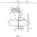
- Figure 1 illustrates power generating equipment that comprises a support structure 1, on which a power generating apparatus (power generating apparatus) 2 is removably engaged.
- the method of engagement of the power generating apparatus 2 with the support structure 1 is not of importance to the present invention.
- a winching device 3 is provided for deployment and retrieval of the power generating apparatus 2 to and from the support structure 1.
- the winching device 3 is shown detached from the power generating apparatus in Figure 1 , and its operation will be described in more detail below.
- the power generating apparatus in Figure 1 is a water current turbine having a blade 2a.
- the principles of the present invention may be applied to any power generating equipment that is deployed in and underwater location.
- the winching device 3 includes a drive unit 4 which operates to draw in or pay out a winch tether 6.
- the winch tether 6 a first elongate portion 6a which extends from a first end 6a1 of the first elongate portion 6a to a second end 6a2 of the first elongate portion 6a, the first end 6a1 of the first elongate portion 6a being connectable to the support structure 1.
- the winch tether 6 also includes a second elongate portion 6b which extends from a first end 6b1 of the second elongate portion 6b to a second end 6b2 of the second elongate portion 6b, the first end 6b1 of the second elongate portion 6b being attached to the winching device 3.
- the winch tether further includes a coupling device 5 operable to connect releasably the second end 6a2 of the first elongate portion 6a of the winch tether 6 with the second end 6b2 of the second elongate portion 6b of the winch tether 6.
- the first portion 6a of the winch tether 6 is attached to the power generating apparatus 2 by way of the coupling device 5.
- the winching device 3 is attached to a surface vessel by an umbilical 7, which supplies electrical power and control signals to the winching device 3.
- the winching device 3 is provided with an alignment feature 11 which engages releasably with a corresponding alignment feature 10 of the power generating apparatus power generating apparatus 2. As will be described in more detail below, the alignment features 10 and 11 enable the winching device 3 to be located on the power generating apparatus 2 at an appropriate position.
- the winching device 3 is rotatable about the alignment features, and can be rotated into the correct alignment with respect to the power generating apparatus 2 using a propulsion device 12, or other suitable means.
- the winching device 3 includes a latching mechanism 13 that engages with corresponding features 14 on the power generating apparatus 2 such that the winching device 3 is aligned with the power generating apparatus 2, and is stable on the power generating apparatus 2 if tether tension is removed.
- a connector 15 is provided in the winching device 3, and is mounted on an actuator 16. The actuator 16 moves the connector 15 into engagement with a receptor 17 on the power generating apparatus 2 when the winching device 3 is aligned with, and mechanically attached to, the power generating apparatus 2.
- the connector 15 is used to supply power and control signals to the power generating apparatus 2 during deployment and retrieval operations.
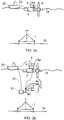
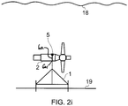
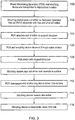
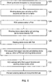
- FIGS. 2a to 2i and 3 are schematic illustrations and a flow chart respectively.
- Figures 2a to 2i illustrate steps 100 to 116 of figure 3 respectively.
- the support structure 1 is located on a sea bed 19, and is prepared for the reception of a power generating apparatus 2 to be mounted thereon.
- the power generating apparatus 2 is towed (step 100) to the location of the support structure 1 by a vessel 20 on the water surface 18.
- the winching device 3 is mounted on the power generating apparatus 2, such that the alignment features 10 and 11 are aligned, and the latching mechanism 13 is engaged with the corresponding features 14 on the power generating apparatus 2.
- the umbilical 7 connects the vessel 20 to the winching device 3.
- a remotely operated vehicle (ROV) 21 is deployed (step 102) from the vessel 20 via a control cable 22, and is used to carry the winch tether 6 to the support structure 1.
- the second end 6a2 of the first portion 6a of the winch tether 6 is connected to the second end 6b2 of the second portion 6b of the winch tether 6 by the coupling device 5.
- the winch drive unit 4 pays out the second portion 6b of the winch tether 6.
- the ROV 21 connects the first end 6a1 of the first portion 6a of the winch tether 6 to the support structure 1, as shown in Figure 2c .
- the winching device 3 operates to take up any slack in the winch tether 6 (step 104), and the ROV is removed from the support structure 1.
- Figure 2d (step 106) illustrates the winching device 3 operating to wind in the second portion 6b of the winch tether 6. Since the winch tether 6 is secured to the support structure 1 by way of the second end 6b2 of the second portion 6b being connected to the second end 6a2 of the first portion 6a, and the first end 6a1 of the first portion 6a being connected to the support structure 1, the winching device 3, and the power generating apparatus 2 are pulled down towards the support structure 1. The coupling device 5 passes through the power generating apparatus 2 prior to the power generating apparatus 2 docking with the support structure 1.
- Figure 2e shows the power generating apparatus 2 docked with the support structure 1.
- the winching device 3 When docking (step 108) is complete, the winching device 3 releases its connections with the power generating apparatus 2 and pays out the second portion 6b of the winch tether 6 for buoyant ascent to the surface 18, as shown in Figure 2f (step110).
- the winch tether 6 remains connected with the power generating apparatus 2 by way of the first end 6a1 of the first portion 6a being attached thereto and the second end 6a2 of the first portion 6a being attached to the second end 6b2 of the second portion 6b by the coupling device 5, such that the ascent can be a controlled manoeuvre.
- the ROV 21 disengages the second end 6b2 of the second portion 6b of the winch tether 6 from the second end 6a2 of the first portion 6a of the winch tether 6 by actuating the coupling device 5 ( Figure 2g , step 112) and the second portion 6b of the winch tether is retracted ( Figure 2h , step 114).
- the first portion 6a of the winch tether 6 and part of the coupling device 5 are left attached to the support structure 1 and power generating apparatus 2 respectively, awaiting use in the retrieval operation which will be described below.
- FIG. 2i shows the completed deployment operation and the winching device 3 can be returned (step 116) to storage or used for further marine operations.
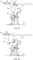
- Figures 4a to 4h illustrate steps in a retrieval process for the power generating apparatus deployed as described with reference to Figures 2a to 2h and 3 .
- Figure 5 is a flowchart showing the steps in such a retrieval process.
- the support structure 1 is located on the seabed 19, and the power generating apparatus 2 is attached to the support structure 1.
- the retrieval process to be described is intended to recover the power generating apparatus 2 to the water surface 18.
- Figure 4b shows the ROV 21 descending with the second end 6b2 of the second portion 6b of the winch tether 6 as the winching device 3 pays out the second portion 6b of the winch tether 6.
- the ROV 21 connects the second end 6b2 of the second portion 6b of the winch tether 6 to the coupling device 5 which is located on the power generating apparatus 2.
- the coupling device 5 is attached to the power generating apparatus 2, and to the second end 6a2 of the first portion 6a of the winch tether 6 attached to the support structure 1.
- the first portion 6a of the winch tether 6 extends through the power generating apparatus 2 to the coupling device 5 which is located on an upper surface of the power generating apparatus 2 where it is accessible by the ROV 21.
- the winching device 3 operates to wind in the second portion 6b of the winch tether 6. Since the winch tether 6 is attached to the support structure 1 by way of the first end 6a1 of the first portion 6a being attached thereto and the second end 6a2 of the first portion 6a being attached to the second end 6b2 of the second portion 6b by the coupling device 5, the action of winding in the tether 6 causes the winching device 3 to be pulled down in to contact with the power generating apparatus 2. This descent is illustrated in Figure 4d (step 126).
- Figure 4e shows the winching device 3 docked with the power generating apparatus 2.
- the winching device 3 locates itself on the power generating apparatus 2 using the engagement features 10 and 11, and then is aligned and secured using the propulsion unit 12 and the latching mechanism 13.
- the actuator 16 operates to enable engagement of the connector 15 with the power generating apparatus 2.
- step 130 the power generating apparatus 2 connection with the support structure 1 is released, and the power generating apparatus 2 and the winching device 3 ascend to the water surface 18 as the winching device 3 pays out the second portion 6b of the winch tether 6.
- the power generating apparatus 2 and the winching device 3 have positive buoyancy, and so ascend without additional assistance, although assistance could be provided by, for example, a crane on the vessel 20.
- the ROV removes (step 132) the end of the winch tether 6 from the support structure 1.
- the winching device 3 then winds in the second portion 6b of the winching tether 6 so that the complete winch tether 6 (including the first and second portions 6a and 6b and the coupling device 5) is fully retracted for transport.
- Figure 4h shows the power generating apparatus 2 and winching device 3 floating on the water surface 18, with the winch tether 6 fully retracted, ready to be transported away from the site (step 134).
Landscapes
- Engineering & Computer Science (AREA)
- General Engineering & Computer Science (AREA)
- Mechanical Engineering (AREA)
- Chemical & Material Sciences (AREA)
- Combustion & Propulsion (AREA)
- Life Sciences & Earth Sciences (AREA)
- General Life Sciences & Earth Sciences (AREA)
- Oceanography (AREA)
- Power Engineering (AREA)
- Civil Engineering (AREA)
- Structural Engineering (AREA)
- Other Liquid Machine Or Engine Such As Wave Power Use (AREA)
Claims (11)
- Stromerzeugungsanlage, umfassend:eine Stützstruktur (1), die dafür ausgelegt ist, auf dem Boden eines Gewässers angeordnet zu werden;eine schwimmende Stromerzeugungsvorrichtung (2), die einen Verdrängungsschwerpunkt hat;eine Windenvorrichtung (3), die lösbar in die Stromerzeugungsvorrichtung (2) eingekuppelt ist und betrieben werden kann, ein Windenseil (6) auszugeben und einzuholen; undein flexibles Windenseil (6),dadurch gekennzeichnet, dass das flexible Windenseil umfasst:einen ersten gestreckten Teil (6a), der sich von einem ersten Ende (6a1) des ersten gestreckten Teils (6a) bis zu einem zweiten Ende (6a2) des ersten gestreckten Teils (6a) erstreckt, wobei das erste Ende (6a1) des ersten gestreckten Teils (6a) mit der Stützstruktur (1) verbunden werden kann;einen zweiten gestreckten Teil (6b), der sich von einem ersten Ende (6b1) des zweiten gestreckten Teils (6b) bis zu einem zweiten Ende (6b2) des zweiten gestreckten Teils (6b) erstreckt, wobei das erste Ende (6b1) des zweiten gestreckten Teils (6b) an der Windenvorrichtung (3) befestigt ist; undeine Kopplungsvorrichtung (5), die zum lösbaren Verbinden des zweiten Endes (6a2) des ersten gestreckten Teils (6a) des Windenseils (6) mit dem zweiten Ende (6b2) des zweiten gestreckten Teils (6b) des Windenseils (6) eingesetzt werden kann,wobei die Windenvorrichtung (3) zum Zurückziehen des flexiblen Windenseils (6) nach der Befestigung des ersten Endes (6a1) des ersten gestreckten Teiles (6a1) des Windenseils (6) an der Stützstruktur (1) und zum Ausgeben des Windenseils (6) nach der Freigabe der Windenvorrichtung (3) von der Stromerzeugungsvorrichtung (2) betrieben werden kann, wodurch die Windenvorrichtung (3) sich von der Stromerzeugungsvorrichtung (2) trennen kann.
- Vorrichtung nach Anspruch 1, wobei die Stützstruktur (1) und die Stromerzeugungsvorrichtung (2) mit zusammenwirkenden Ausrichtungsteilen versehen sind, die eine verbindende Achse definieren, die dafür ausgelegt sind, die Stromerzeugungsvorrichtung (2) zu einem Eingriff in die Stützstruktur (1) zu führen, derart dass, wenn die Vorrichtung in Betrieb ist, das Zurückziehen des Windenseils (6) durch die Windenvorrichtung bewirkt, dass die Stromerzeugungsvorrichtung (2) nach unten durch das Gewässer in einen Eingriff mit der Stützstruktur (1) gezogen wird, wobei der Verdrängungsschwerpunkt der Stromerzeugungsvorrichtung (2) im Wesentlichen in Übereinstimmung mit der verbindenden Achse vor einem solchen Eingriff ist, und wobei die Stützstruktur (1) und die Stromerzeugungsvorrichtung (2) Mittel zum Befestigen der Stromerzeugungsvorrichtung (2) an der Stützstruktur (1) enthalten.
- Vorrichtung nach Anspruch 2, wobei die Mittel zum Befestigen elektrische, hydraulische und faseroptische Verbinder zwischen der Stromerzeugungsvorrichtung (2) und der Stützstruktur (1) umfassen.
- Vorrichtung nach Anspruch 1, 2 oder 3, wobei die Windenvorrichtung (3) und die Stromerzeugungsvorrichtung (2) komplementäre Ausrichtungsmerkmale (11, 10) zum Ausrichten der Windenvorrichtung (3) in Bezug auf die Stromerzeugungsvorrichtung (2) enthalten.
- Vorrichtung nach einem der vorhergehenden Ansprüche, wobei die Windenvorrichtung (3) eine Ausrichtungseinheit umfasst, die zum Ausrichten der Windenvorrichtung (3) gegenüber der Stromerzeugungsvorrichtung (2) betrieben werden kann.
- Vorrichtung nach einem der vorhergehenden Ansprüche, wobei Windenvorrichtung (3) und die Stromerzeugungsvorrichtung (2) komplementäre Einrastungskomponenten (13, 14) zum lösbaren Befestigen der Windenvorrichtung (3) an der Stromerzeugungsvorrichtung (2) umfassen.
- Vorrichtung nach einem der vorhergehenden Ansprüche, wobei die Kopplungsvorrichtung (5) zum Verbinden und Trennen der ersten und zweiten Teile (6a, 6b) des Windenseils (6) unter Verwendung eines fernbetriebenen Fahrzeugs (21) betrieben werden kann.
- Vorrichtung nach einem der vorhergehenden Ansprüche, wobei die Windenvorrichtung (3) schwimmfähig ist.
- Verfahren zum Einsetzen einer absenkbaren, schwimmfähigen Stromerzeugungsvorrichtung auf einer untergetauchten Stützstruktur (1), die auf einem Boden eines Gewässers angeordnet ist, wobei die Stromerzeugungsvorrichtung (2) eine Windenvorrichtung (3) trägt, die lösbar mit der Stromerzeugungsvorrichtung (2) im Eingriff ist, die zum Ausgeben und zum Zurückziehen eines flexiblen Windenseils (6) betrieben werden kann, wobei das flexible Windenseil (6) einen ersten gestreckten Teil (6a) hat, der sich von einem ersten Ende (6a1) des ersten gestreckten Teils (6a) bis zu einem zweiten Ende (6a2) des ersten gestreckten Teils (6a) erstreckt, wobei das erste Ende (6a1) des ersten gestreckten Teils (6a) mit der Stützstruktur (1) verbunden werden kann, ein zweiter gestreckter Teil (6b), der sich von einem ersten Ende (6b1) des zweiten gestreckten Teils (6b) bis zu einem zweiten Ende (6b2) des zweiten gestreckten Teils (6b) erstreckt, wobei das erste Ende (6b1) des zweiten gestreckten Teils (6b) an der Windenvorrichtung (3) befestigt ist, und eine Kopplungsvorrichtung (5), die zum lösbaren Verbinden des zweiten Endes (6a2) ersten gestreckten Teils (6a) des Windenseils (6) mit dem zweiten Ende (6b2) des zweiten gestreckten Teils (6b) des Windenseils (6) eingesetzt werden kann, wobei das Verfahren umfasst:Befestigen des ersten Endes (6a1) des ersten Teils (6a) des Windenseils (6) an der Stützstruktur (1);Betreiben der Windenvorrichtung (3) zum Zurückziehen des zweiten Teils (6b) des Windenseils (6) in die Windenvorrichtung (3), derart, dass die Stromerzeugungsvorrichtung (2) und die Windenvorrichtung (3) nach unten durch das Gewässer derart gezogen werden, dass die Stromerzeugungsvorrichtung (2) in den Eingriff mit der Stützstruktur (1) gebracht wird;Befestigen der Stromerzeugungsvorrichtung (2) im Eingriff mit der Stützstruktur (1) unter Verwendung von Befestigungsmitteln, die auf der Stützstruktur (1) und der Stromerzeugungsvorrichtung (2) vorgesehen sind;Abklemmen der Windenvorrichtung (3) von der Stromerzeugungsvorrichtung (2);Ausgeben des zweiten Teils (6b) des Windenseils (6) von der Windenvorrichtung (3) derart, dass die Windenvorrichtung (3) zur Oberfläche des Gewässers aufsteigt;Betätigen der Kopplungsvorrichtung, um so das zweite Ende (6a2) des ersten Teils (6a) des Windenseils (6) vom zweiten Ende (6b2) des zweiten Teils (6b) des Windenseils (6) zu trennen; undZurückziehen des zweiten Teils (6b) des Windenseils (6) in die Windenvorrichtung (3).
- Verfahren nach Anspruch 9, wobei die Stromversorgungsvorrichtung (2) ein Verdrängungszentrum hat und die Stützstruktur (1) eine verbindende Achse hat, wobei das Verdrängungszentrum der Stromversorgungsvorrichtung (2) im Wesentlichen in Übereinstimmung mit der verbindenden Achse vor dem Eingriff derselben ist.
- Verfahren zum Rückgewinnen einer schwimmfähigen Stromerzeugungsvorrichtung, die auf einer Stützstruktur (1) befestigt ist, welche sich am Boden eines Gewässers befindet, wobei die Stromerzeugungsvorrichtung (2) einen ersten gestreckten Teil (6a) eines Windenseils (6) enthält, wobei der erste gestreckten Teil (6a) des Windenseils sich von einem ersten Ende (6a1) des ersten gestreckten Teil (6a) bis zu einem zweiten Ende (6a2) des ersten gestreckten Teils (6a) erstreckt, wobei das erste Ende (6a1) des ersten gestreckten Teils (6a) an der Stützstruktur (1) befestigt ist, wobei das Windenseil ferner einen zweiten gestreckten Teil (6b) umfasst, der sich von einem ersten Ende (6b1) des zweiten gestreckten Teils (6b) bis zu einem zweiten Ende (6b2) des zweiten gestreckten Teils (6b) erstreckt, wobei das erste Ende (6b1) des zweiten gestreckten Teils (6b) an der Windenvorrichtung (3) befestigt ist, und eine Kopplungsvorrichtung (5), die zum lösbaren Verbinden des zweiten Endes (6a2) des ersten gestreckten Teils (6a) des Windenseils (6) mit dem zweiten Ende (6b2) des zweiten gestreckten Teils (6b) des Windenseils (6) eingesetzt werden kann, wobei das Verfahren umfasst:Auslösen der Kopplungsvorrichtung (5) zum Befestigen des zweiten Endes (6b2) des zweiten Teils (6b) des Windenseils (6) am zweiten Ende (6a2) des ersten Teils (6a) des Windenseils (6);Zurückziehen des zweiten Teils (6b) des Windenseils (6) unter Verwendung der Windenvorrichtung (3), dadurch bewirken, dass Windenvorrichtung (3) sich zur Stromerzeugungsvorrichtung (2) bewegt;Platzieren der Winden (3) auf der Stromerzeugungsvorrichtung (2) und Einklinken der Windenvorrichtung (3) in die Stromerzeugungsvorrichtung (2);Ermöglichen, dass die Stromerzeugungsvorrichtung (2) und die Windenvorrichtung (3) zur Oberfläche des Gewässers treiben; undAbnehmen des ersten Endes (6a1) des ersten Teils (6a) des Windenseils (6) von der Stützstruktur (1).
Applications Claiming Priority (2)
| Application Number | Priority Date | Filing Date | Title |
|---|---|---|---|
| GB201021800A GB2486697B (en) | 2010-12-23 | 2010-12-23 | Power generating equipment |
| PCT/GB2011/052397 WO2012085530A1 (en) | 2010-12-23 | 2011-12-05 | Power generating equipment |
Publications (2)
| Publication Number | Publication Date |
|---|---|
| EP2655869A1 EP2655869A1 (de) | 2013-10-30 |
| EP2655869B1 true EP2655869B1 (de) | 2017-02-15 |
Family
ID=43598855
Family Applications (1)
| Application Number | Title | Priority Date | Filing Date |
|---|---|---|---|
| EP11796789.3A Not-in-force EP2655869B1 (de) | 2010-12-23 | 2011-12-05 | Energieerzeugungsvorrichtung |
Country Status (8)
| Country | Link |
|---|---|
| US (1) | US9086049B2 (de) |
| EP (1) | EP2655869B1 (de) |
| KR (1) | KR20140006832A (de) |
| AU (1) | AU2011346904A1 (de) |
| CA (1) | CA2822405C (de) |
| CL (1) | CL2013001865A1 (de) |
| GB (1) | GB2486697B (de) |
| WO (1) | WO2012085530A1 (de) |
Families Citing this family (15)
| Publication number | Priority date | Publication date | Assignee | Title |
|---|---|---|---|---|
| DE102010033788A1 (de) * | 2010-08-09 | 2012-02-09 | Voith Patent Gmbh | Verfahren und Vorrichtung zur Installation eines Gezeltenkraftwerks |
| GB2490737B (en) * | 2011-05-13 | 2013-04-10 | Sustainable Marine Technologies Ltd | A modular turbine assembly |
| US9938958B2 (en) | 2012-07-19 | 2018-04-10 | Humberto Antonio RUBIO | Vertical axis wind and hydraulic turbine with flow control |
| GB2504516A (en) * | 2012-08-01 | 2014-02-05 | Tidal Generation Ltd | A sub aquatic coupling for electrical connection hub |
| DE102013005029A1 (de) * | 2013-03-25 | 2014-09-25 | Voith Patent Gmbh | Unterwasser-Strömungskraftwerk |
| GB2514849B (en) * | 2013-06-09 | 2015-12-23 | Tidal Generation Ltd | Power generating systems |
| GB2515011B (en) | 2013-06-10 | 2015-06-10 | Tidal Generation Ltd | Power generating equipment |
| US9855999B1 (en) | 2014-01-10 | 2018-01-02 | Wt Industries, Llc | System for launch and recovery of remotely operated vehicles |
| US9540076B1 (en) * | 2014-01-10 | 2017-01-10 | Wt Industries, Llc | System for launch and recovery of remotely operated vehicles |
| US10328999B2 (en) * | 2014-01-10 | 2019-06-25 | Wt Industries, Llc | System for launch and recovery of remotely operated vehicles |
| GB2550148B (en) * | 2016-05-10 | 2019-06-19 | Tidal Generation Ltd | Deploying submerged power connectors |
| GB2550871B (en) * | 2016-05-26 | 2019-04-17 | Tidal Generation Ltd | Deploying submerged equipment |
| CN111622889B (zh) * | 2020-06-10 | 2025-02-07 | 杭州林黄丁新能源研究院有限公司 | 大型潮流能发电装置及其总成平台 |
| DK4288368T3 (da) * | 2021-02-08 | 2024-12-16 | Grant Prideco Inc | Apparat, system og fremgangsmåder til bevægelse af en last mellem et flydende fartøj og en nedsækket position |
| US20240352699A1 (en) * | 2023-04-03 | 2024-10-24 | Mark A. Danaczko | Submersible offshore platform and method of installing the same |
Family Cites Families (9)
| Publication number | Priority date | Publication date | Assignee | Title |
|---|---|---|---|---|
| US3880103A (en) * | 1972-08-21 | 1975-04-29 | Us Navy | Tethered mine hunting system |
| US4512886A (en) * | 1981-05-26 | 1985-04-23 | University Of Delaware | Wave-powered desalination of water |
| GB2431628B (en) * | 2005-10-31 | 2009-01-28 | Tidal Generation Ltd | A deployment and retrieval apparatus for submerged power generating devices |
| GB2431207B (en) * | 2005-10-14 | 2010-10-13 | Tidal Generation Ltd | A flow alignment device for water current power generating apparatus |
| GB2448710B (en) * | 2007-04-24 | 2009-03-11 | Tidal Generation Ltd | A Mechanical connection system for submerged marine power generating devices |
| EP2162618B1 (de) * | 2007-06-29 | 2012-09-26 | Aquantis, Inc. | Unterwasserströmungsturbine |
| US20110089696A1 (en) * | 2008-02-26 | 2011-04-21 | Trex Enterprises Corp. | Power generating buoy |
| JP2011516779A (ja) * | 2008-04-11 | 2011-05-26 | オーストラリアン サステイナブル エナジー コーポレーション プロプライアタリー リミテッド | 波エネルギー変換器を配置し回収するためのシステム及び方法 |
| GB2460309A (en) | 2008-05-27 | 2009-12-02 | Marine Power Systems Ltd | Submersible turbine apparatus |
-
2010
- 2010-12-23 GB GB201021800A patent/GB2486697B/en not_active Expired - Fee Related
-
2011
- 2011-12-05 WO PCT/GB2011/052397 patent/WO2012085530A1/en not_active Ceased
- 2011-12-05 EP EP11796789.3A patent/EP2655869B1/de not_active Not-in-force
- 2011-12-05 AU AU2011346904A patent/AU2011346904A1/en not_active Abandoned
- 2011-12-05 US US13/997,428 patent/US9086049B2/en active Active
- 2011-12-05 CA CA2822405A patent/CA2822405C/en active Active
- 2011-12-05 KR KR20137019381A patent/KR20140006832A/ko not_active Withdrawn
-
2013
- 2013-06-24 CL CL2013001865A patent/CL2013001865A1/es unknown
Non-Patent Citations (1)
| Title |
|---|
| None * |
Also Published As
| Publication number | Publication date |
|---|---|
| GB2486697B (en) | 2013-05-29 |
| CA2822405C (en) | 2019-03-12 |
| US9086049B2 (en) | 2015-07-21 |
| CA2822405A1 (en) | 2012-06-28 |
| EP2655869A1 (de) | 2013-10-30 |
| US20130333371A1 (en) | 2013-12-19 |
| WO2012085530A1 (en) | 2012-06-28 |
| GB2486697A (en) | 2012-06-27 |
| CL2013001865A1 (es) | 2014-08-18 |
| GB201021800D0 (en) | 2011-02-02 |
| AU2011346904A1 (en) | 2013-07-25 |
| KR20140006832A (ko) | 2014-01-16 |
Similar Documents
| Publication | Publication Date | Title |
|---|---|---|
| EP2655869B1 (de) | Energieerzeugungsvorrichtung | |
| EP1945940B1 (de) | Ausbringvorrichtung für unterwassertriebwerk | |
| CN109790697B (zh) | 用于安装海底线缆的组件和方法 | |
| KR101741558B1 (ko) | 조력 발전 장치를 설치하는 방법 및 장치 | |
| EP3008329B1 (de) | Stromerzeugungssysteme | |
| CA2846126A1 (en) | Underwater turbine anchorage | |
| EP3994055B1 (de) | Offshore-bohrschiff mit einer externen kabelverbindung und verfahren dafür | |
| WO2014032106A1 (en) | Buoy | |
| EP3008328B1 (de) | Energieerzeugungsvorrichtung | |
| DK181182B1 (en) | An offshore drilling vessel with an external cable connection and method therefor | |
| GB2531947A (en) | Power generating systems | |
| GB2514773A (en) | Underwater turbine installation apparatus and methods | |
| KR102020108B1 (ko) | 해저 케이블 설치가 용이한 조류발전장치 시공 시스템 | |
| EP3455492B1 (de) | Einsatz untergetauchter leistungssteckverbinder | |
| WO2025032109A1 (en) | System and method for transferring an end of a power cable | |
| WO2025032110A1 (en) | System and method for connecting a power cable |
Legal Events
| Date | Code | Title | Description |
|---|---|---|---|
| PUAI | Public reference made under article 153(3) epc to a published international application that has entered the european phase |
Free format text: ORIGINAL CODE: 0009012 |
|
| 17P | Request for examination filed |
Effective date: 20130723 |
|
| AK | Designated contracting states |
Kind code of ref document: A1 Designated state(s): AL AT BE BG CH CY CZ DE DK EE ES FI FR GB GR HR HU IE IS IT LI LT LU LV MC MK MT NL NO PL PT RO RS SE SI SK SM TR |
|
| RAP1 | Party data changed (applicant data changed or rights of an application transferred) |
Owner name: TIDAL GENERATION LIMITED |
|
| DAX | Request for extension of the european patent (deleted) | ||
| 17Q | First examination report despatched |
Effective date: 20141210 |
|
| REG | Reference to a national code |
Ref country code: DE Ref legal event code: R079 Ref document number: 602011035071 Country of ref document: DE Free format text: PREVIOUS MAIN CLASS: F03B0013260000 Ipc: E02B0017020000 |
|
| RIC1 | Information provided on ipc code assigned before grant |
Ipc: E02B 17/08 20060101ALI20160809BHEP Ipc: E02B 17/02 20060101AFI20160809BHEP Ipc: F03B 13/10 20060101ALI20160809BHEP Ipc: F03B 13/26 20060101ALI20160809BHEP Ipc: F03B 17/06 20060101ALI20160809BHEP Ipc: E02B 9/08 20060101ALI20160809BHEP |
|
| GRAP | Despatch of communication of intention to grant a patent |
Free format text: ORIGINAL CODE: EPIDOSNIGR1 |
|
| INTG | Intention to grant announced |
Effective date: 20160929 |
|
| GRAS | Grant fee paid |
Free format text: ORIGINAL CODE: EPIDOSNIGR3 |
|
| GRAA | (expected) grant |
Free format text: ORIGINAL CODE: 0009210 |
|
| AK | Designated contracting states |
Kind code of ref document: B1 Designated state(s): AL AT BE BG CH CY CZ DE DK EE ES FI FR GB GR HR HU IE IS IT LI LT LU LV MC MK MT NL NO PL PT RO RS SE SI SK SM TR |
|
| REG | Reference to a national code |
Ref country code: CH Ref legal event code: EP Ref country code: GB Ref legal event code: FG4D |
|
| REG | Reference to a national code |
Ref country code: IE Ref legal event code: FG4D |
|
| REG | Reference to a national code |
Ref country code: AT Ref legal event code: REF Ref document number: 867975 Country of ref document: AT Kind code of ref document: T Effective date: 20170315 |
|
| REG | Reference to a national code |
Ref country code: DE Ref legal event code: R096 Ref document number: 602011035071 Country of ref document: DE |
|
| REG | Reference to a national code |
Ref country code: NL Ref legal event code: MP Effective date: 20170215 |
|
| REG | Reference to a national code |
Ref country code: LT Ref legal event code: MG4D |
|
| REG | Reference to a national code |
Ref country code: AT Ref legal event code: MK05 Ref document number: 867975 Country of ref document: AT Kind code of ref document: T Effective date: 20170215 |
|
| PG25 | Lapsed in a contracting state [announced via postgrant information from national office to epo] |
Ref country code: NO Free format text: LAPSE BECAUSE OF FAILURE TO SUBMIT A TRANSLATION OF THE DESCRIPTION OR TO PAY THE FEE WITHIN THE PRESCRIBED TIME-LIMIT Effective date: 20170515 Ref country code: FI Free format text: LAPSE BECAUSE OF FAILURE TO SUBMIT A TRANSLATION OF THE DESCRIPTION OR TO PAY THE FEE WITHIN THE PRESCRIBED TIME-LIMIT Effective date: 20170215 Ref country code: HR Free format text: LAPSE BECAUSE OF FAILURE TO SUBMIT A TRANSLATION OF THE DESCRIPTION OR TO PAY THE FEE WITHIN THE PRESCRIBED TIME-LIMIT Effective date: 20170215 Ref country code: GR Free format text: LAPSE BECAUSE OF FAILURE TO SUBMIT A TRANSLATION OF THE DESCRIPTION OR TO PAY THE FEE WITHIN THE PRESCRIBED TIME-LIMIT Effective date: 20170516 Ref country code: LT Free format text: LAPSE BECAUSE OF FAILURE TO SUBMIT A TRANSLATION OF THE DESCRIPTION OR TO PAY THE FEE WITHIN THE PRESCRIBED TIME-LIMIT Effective date: 20170215 |
|
| PG25 | Lapsed in a contracting state [announced via postgrant information from national office to epo] |
Ref country code: SE Free format text: LAPSE BECAUSE OF FAILURE TO SUBMIT A TRANSLATION OF THE DESCRIPTION OR TO PAY THE FEE WITHIN THE PRESCRIBED TIME-LIMIT Effective date: 20170215 Ref country code: RS Free format text: LAPSE BECAUSE OF FAILURE TO SUBMIT A TRANSLATION OF THE DESCRIPTION OR TO PAY THE FEE WITHIN THE PRESCRIBED TIME-LIMIT Effective date: 20170215 Ref country code: PT Free format text: LAPSE BECAUSE OF FAILURE TO SUBMIT A TRANSLATION OF THE DESCRIPTION OR TO PAY THE FEE WITHIN THE PRESCRIBED TIME-LIMIT Effective date: 20170615 Ref country code: NL Free format text: LAPSE BECAUSE OF FAILURE TO SUBMIT A TRANSLATION OF THE DESCRIPTION OR TO PAY THE FEE WITHIN THE PRESCRIBED TIME-LIMIT Effective date: 20170215 Ref country code: LV Free format text: LAPSE BECAUSE OF FAILURE TO SUBMIT A TRANSLATION OF THE DESCRIPTION OR TO PAY THE FEE WITHIN THE PRESCRIBED TIME-LIMIT Effective date: 20170215 Ref country code: ES Free format text: LAPSE BECAUSE OF FAILURE TO SUBMIT A TRANSLATION OF THE DESCRIPTION OR TO PAY THE FEE WITHIN THE PRESCRIBED TIME-LIMIT Effective date: 20170215 Ref country code: AT Free format text: LAPSE BECAUSE OF FAILURE TO SUBMIT A TRANSLATION OF THE DESCRIPTION OR TO PAY THE FEE WITHIN THE PRESCRIBED TIME-LIMIT Effective date: 20170215 Ref country code: BG Free format text: LAPSE BECAUSE OF FAILURE TO SUBMIT A TRANSLATION OF THE DESCRIPTION OR TO PAY THE FEE WITHIN THE PRESCRIBED TIME-LIMIT Effective date: 20170515 |
|
| PG25 | Lapsed in a contracting state [announced via postgrant information from national office to epo] |
Ref country code: SK Free format text: LAPSE BECAUSE OF FAILURE TO SUBMIT A TRANSLATION OF THE DESCRIPTION OR TO PAY THE FEE WITHIN THE PRESCRIBED TIME-LIMIT Effective date: 20170215 Ref country code: CZ Free format text: LAPSE BECAUSE OF FAILURE TO SUBMIT A TRANSLATION OF THE DESCRIPTION OR TO PAY THE FEE WITHIN THE PRESCRIBED TIME-LIMIT Effective date: 20170215 Ref country code: RO Free format text: LAPSE BECAUSE OF FAILURE TO SUBMIT A TRANSLATION OF THE DESCRIPTION OR TO PAY THE FEE WITHIN THE PRESCRIBED TIME-LIMIT Effective date: 20170215 Ref country code: EE Free format text: LAPSE BECAUSE OF FAILURE TO SUBMIT A TRANSLATION OF THE DESCRIPTION OR TO PAY THE FEE WITHIN THE PRESCRIBED TIME-LIMIT Effective date: 20170215 Ref country code: IT Free format text: LAPSE BECAUSE OF FAILURE TO SUBMIT A TRANSLATION OF THE DESCRIPTION OR TO PAY THE FEE WITHIN THE PRESCRIBED TIME-LIMIT Effective date: 20170215 |
|
| REG | Reference to a national code |
Ref country code: DE Ref legal event code: R097 Ref document number: 602011035071 Country of ref document: DE |
|
| PG25 | Lapsed in a contracting state [announced via postgrant information from national office to epo] |
Ref country code: SM Free format text: LAPSE BECAUSE OF FAILURE TO SUBMIT A TRANSLATION OF THE DESCRIPTION OR TO PAY THE FEE WITHIN THE PRESCRIBED TIME-LIMIT Effective date: 20170215 Ref country code: PL Free format text: LAPSE BECAUSE OF FAILURE TO SUBMIT A TRANSLATION OF THE DESCRIPTION OR TO PAY THE FEE WITHIN THE PRESCRIBED TIME-LIMIT Effective date: 20170215 Ref country code: DK Free format text: LAPSE BECAUSE OF FAILURE TO SUBMIT A TRANSLATION OF THE DESCRIPTION OR TO PAY THE FEE WITHIN THE PRESCRIBED TIME-LIMIT Effective date: 20170215 |
|
| PLBE | No opposition filed within time limit |
Free format text: ORIGINAL CODE: 0009261 |
|
| STAA | Information on the status of an ep patent application or granted ep patent |
Free format text: STATUS: NO OPPOSITION FILED WITHIN TIME LIMIT |
|
| REG | Reference to a national code |
Ref country code: FR Ref legal event code: PLFP Year of fee payment: 7 |
|
| 26N | No opposition filed |
Effective date: 20171116 |
|
| PG25 | Lapsed in a contracting state [announced via postgrant information from national office to epo] |
Ref country code: SI Free format text: LAPSE BECAUSE OF FAILURE TO SUBMIT A TRANSLATION OF THE DESCRIPTION OR TO PAY THE FEE WITHIN THE PRESCRIBED TIME-LIMIT Effective date: 20170215 |
|
| REG | Reference to a national code |
Ref country code: DE Ref legal event code: R119 Ref document number: 602011035071 Country of ref document: DE |
|
| REG | Reference to a national code |
Ref country code: CH Ref legal event code: PL |
|
| GBPC | Gb: european patent ceased through non-payment of renewal fee |
Effective date: 20171205 |
|
| REG | Reference to a national code |
Ref country code: IE Ref legal event code: MM4A |
|
| PG25 | Lapsed in a contracting state [announced via postgrant information from national office to epo] |
Ref country code: MT Free format text: LAPSE BECAUSE OF NON-PAYMENT OF DUE FEES Effective date: 20171205 Ref country code: LU Free format text: LAPSE BECAUSE OF NON-PAYMENT OF DUE FEES Effective date: 20171205 |
|
| REG | Reference to a national code |
Ref country code: BE Ref legal event code: MM Effective date: 20171231 |
|
| PG25 | Lapsed in a contracting state [announced via postgrant information from national office to epo] |
Ref country code: DE Free format text: LAPSE BECAUSE OF NON-PAYMENT OF DUE FEES Effective date: 20180703 Ref country code: IE Free format text: LAPSE BECAUSE OF NON-PAYMENT OF DUE FEES Effective date: 20171205 |
|
| PG25 | Lapsed in a contracting state [announced via postgrant information from national office to epo] |
Ref country code: GB Free format text: LAPSE BECAUSE OF NON-PAYMENT OF DUE FEES Effective date: 20171205 Ref country code: BE Free format text: LAPSE BECAUSE OF NON-PAYMENT OF DUE FEES Effective date: 20171231 Ref country code: LI Free format text: LAPSE BECAUSE OF NON-PAYMENT OF DUE FEES Effective date: 20171231 Ref country code: CH Free format text: LAPSE BECAUSE OF NON-PAYMENT OF DUE FEES Effective date: 20171231 |
|
| PG25 | Lapsed in a contracting state [announced via postgrant information from national office to epo] |
Ref country code: HU Free format text: LAPSE BECAUSE OF FAILURE TO SUBMIT A TRANSLATION OF THE DESCRIPTION OR TO PAY THE FEE WITHIN THE PRESCRIBED TIME-LIMIT; INVALID AB INITIO Effective date: 20111205 Ref country code: MC Free format text: LAPSE BECAUSE OF FAILURE TO SUBMIT A TRANSLATION OF THE DESCRIPTION OR TO PAY THE FEE WITHIN THE PRESCRIBED TIME-LIMIT Effective date: 20170215 |
|
| PG25 | Lapsed in a contracting state [announced via postgrant information from national office to epo] |
Ref country code: CY Free format text: LAPSE BECAUSE OF NON-PAYMENT OF DUE FEES Effective date: 20170215 |
|
| PG25 | Lapsed in a contracting state [announced via postgrant information from national office to epo] |
Ref country code: MK Free format text: LAPSE BECAUSE OF FAILURE TO SUBMIT A TRANSLATION OF THE DESCRIPTION OR TO PAY THE FEE WITHIN THE PRESCRIBED TIME-LIMIT Effective date: 20170215 |
|
| PG25 | Lapsed in a contracting state [announced via postgrant information from national office to epo] |
Ref country code: TR Free format text: LAPSE BECAUSE OF FAILURE TO SUBMIT A TRANSLATION OF THE DESCRIPTION OR TO PAY THE FEE WITHIN THE PRESCRIBED TIME-LIMIT Effective date: 20170215 |
|
| PG25 | Lapsed in a contracting state [announced via postgrant information from national office to epo] |
Ref country code: AL Free format text: LAPSE BECAUSE OF FAILURE TO SUBMIT A TRANSLATION OF THE DESCRIPTION OR TO PAY THE FEE WITHIN THE PRESCRIBED TIME-LIMIT Effective date: 20170215 Ref country code: IS Free format text: LAPSE BECAUSE OF FAILURE TO SUBMIT A TRANSLATION OF THE DESCRIPTION OR TO PAY THE FEE WITHIN THE PRESCRIBED TIME-LIMIT Effective date: 20170615 |
|
| PGFP | Annual fee paid to national office [announced via postgrant information from national office to epo] |
Ref country code: FR Payment date: 20221223 Year of fee payment: 12 |
|
| PG25 | Lapsed in a contracting state [announced via postgrant information from national office to epo] |
Ref country code: FR Free format text: LAPSE BECAUSE OF NON-PAYMENT OF DUE FEES Effective date: 20231231 |
|
| PG25 | Lapsed in a contracting state [announced via postgrant information from national office to epo] |
Ref country code: FR Free format text: LAPSE BECAUSE OF NON-PAYMENT OF DUE FEES Effective date: 20231231 |